WO2025009020A1 - 電磁式燃料噴射弁 - Google Patents
電磁式燃料噴射弁 Download PDFInfo
- Publication number
- WO2025009020A1 WO2025009020A1 PCT/JP2023/024630 JP2023024630W WO2025009020A1 WO 2025009020 A1 WO2025009020 A1 WO 2025009020A1 JP 2023024630 W JP2023024630 W JP 2023024630W WO 2025009020 A1 WO2025009020 A1 WO 2025009020A1
- Authority
- WO
- WIPO (PCT)
- Prior art keywords
- rod
- movable core
- fuel injection
- annular guide
- injection valve
- Prior art date
- Legal status (The legal status is an assumption and is not a legal conclusion. Google has not performed a legal analysis and makes no representation as to the accuracy of the status listed.)
- Ceased
Links
Images

Classifications
-
- F—MECHANICAL ENGINEERING; LIGHTING; HEATING; WEAPONS; BLASTING
- F02—COMBUSTION ENGINES; HOT-GAS OR COMBUSTION-PRODUCT ENGINE PLANTS
- F02M—SUPPLYING COMBUSTION ENGINES IN GENERAL WITH COMBUSTIBLE MIXTURES OR CONSTITUENTS THEREOF
- F02M51/00—Fuel-injection apparatus characterised by being operated electrically
- F02M51/06—Injectors peculiar thereto with means directly operating the valve needle
-
- F—MECHANICAL ENGINEERING; LIGHTING; HEATING; WEAPONS; BLASTING
- F02—COMBUSTION ENGINES; HOT-GAS OR COMBUSTION-PRODUCT ENGINE PLANTS
- F02M—SUPPLYING COMBUSTION ENGINES IN GENERAL WITH COMBUSTIBLE MIXTURES OR CONSTITUENTS THEREOF
- F02M61/00—Fuel-injectors not provided for in groups F02M39/00 - F02M57/00 or F02M67/00
- F02M61/04—Fuel-injectors not provided for in groups F02M39/00 - F02M57/00 or F02M67/00 having valves, e.g. having a plurality of valves in series
- F02M61/08—Fuel-injectors not provided for in groups F02M39/00 - F02M57/00 or F02M67/00 having valves, e.g. having a plurality of valves in series the valves opening in direction of fuel flow
Definitions
- the present invention relates to an electromagnetic fuel injection valve used in a fuel supply system.
- Patent Document 1 describes an electromagnetic injection valve that has a valve housing with a valve seat on one end and a fixed core on the other end, a rod disposed within the valve housing, and a movable core that slides on the outer circumference of the rod.
- NiP plating has been applied to the entire axial area of the inner circumferential surface defined by the through hole of the movable core, and then Cr plating has been applied to both axial ends of the inner circumferential surface to further improve durability.
- the present invention aims to provide an electromagnetic fuel injection valve that is low-cost and prevents malfunctions caused by the inclusion of foreign matter.
- the electromagnetic fuel injection valve of the present invention comprises: A rod and a movable core,
- the movable core is provided with a total of two annular guide portions which are annularly arranged protrusions along the circumferential direction of the inner surface defined by the through hole of the movable core and/or on the outer surface of the rod facing the inner surface, and which are arranged spaced apart from each other in the axial direction of the rod to guide the movement of the movable core relative to the rod.
- the present invention provides an electromagnetic fuel injection valve that is low-cost and prevents malfunctions caused by the inclusion of foreign matter.
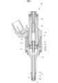
- FIG. 1 is a cross-sectional view of an electromagnetic fuel injection valve according to an embodiment of the present invention.
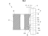
- 1 is an enlarged cross-sectional view of a main portion of an electromagnetic fuel injection valve according to a first embodiment of the present invention
- FIG. 5 is an enlarged cross-sectional view of a main portion of an electromagnetic fuel injection valve according to a second embodiment of the present invention
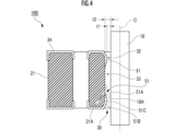
- FIG. 11 is an enlarged cross-sectional view of a main portion of an electromagnetic fuel injection valve according to a third embodiment of the present invention.
- Fig. 1 shows an electromagnetic fuel injection valve 10 according to an embodiment of the present invention.
- the electromagnetic fuel injection valve 10 of the first embodiment includes a valve housing 13 in which a fuel injection hole 11 and a valve seat 12 are formed, a valve body 15 that enables fuel injection from the fuel injection hole 11 by lifting the valve body 15 from a closed position in contact with the valve seat 12 to an open position in response to excitation of a coil 14, and a return spring 16 that returns the valve body 15 to the closed position in contact with the valve seat 12.
- the lift of the valve body 15 to the open position is achieved by settling the overshoot and overshoot return that occur during the lift.
- the valve body 15 has a rod 18 connected to a valve portion 17 that cooperates with the valve seat 12.
- the rod 18 is formed in a cylindrical shape that extends in the axial direction.
- the electromagnetic fuel injection valve 10 also includes a hollow fixed core 19 connected to the upstream end of the valve housing 13, a movable core 21 that faces an attraction surface 20 of the fixed core 19, has a through hole 30 into which the rod 18 is inserted, and moves in the axial direction of the rod 18, and a valve-opening stopper 22 that is fixed to the rod 18 and comes into contact with the movable core 21 that is attracted to the attraction surface 20 when the coil 14 is energized, thereby opening the valve body 15.
- a chromium (Cr) plating layer 34 is applied to the entire upper and lower surfaces of the movable core 21 (surfaces formed in a direction perpendicular to the axial direction of the rod 18).
- the closing side stopper 23 is fixed to the rod 18 closer to the valve seat 12 than the opening side stopper 22.
- An auxiliary spring 24 is provided between the opening side stopper 22 and the movable core 21 to exert a spring force that moves the movable core 21 away from the opening side stopper 22 and into contact with the closing side stopper 23 when the coil 14 is not energized.
- the movable core 21 When the movable core 21 comes into contact with the opening stopper 22, it quickly moves the opening stopper 22 against the biasing force of the return spring 16, and collides with the suction surface 20, stopping it. During this time, the rod 18 moves together with the opening stopper 22, so that the valve portion 17 at the tip of the rod 18 leaves the valve seat 12, and the valve is opened.
- valve portion 17 When the valve portion 17 opens, fuel is pumped from a fuel pump (not shown) into the fuel supply tube 25 and passes through the inside of the pipe-shaped retainer 26, the hollow portion 27 of the fixed core 19, the side portion around the valve-opening stopper 22, the through hole 28 of the movable core 21, the inside of the valve housing 13, and the flat portion 29 around the valve portion 17, before being injected directly into the combustion chamber of the internal combustion engine through the fuel injection hole 11.
- a fuel pump not shown
- Figure 2 is an enlarged cross-sectional view of the main portion of the sliding portion between the rod 18 and the movable core 21 into which the rod 18 is inserted of the electromagnetic fuel injection valve 10 according to the first embodiment of the present invention. Note that in Figure 2, one side of the movable core 21 (the right side in the figure) is omitted (the same applies to Figures 3 and 4).
- annular guide portions 31 are formed on the inner peripheral surface 21A defined by the through hole 30 of the movable core 21.
- the annular guide portions 31 regulate the swinging range of the movable core 21 when the movable core 21 slides relative to the rod 18, improving the linearity of the movable core 21 when it moves in the axial direction of the rod 18.
- annular guide portions 31, 31 are respectively protruded from one axial end and the other axial end of the movable core 21 on the inner peripheral surface 21A of the movable core 21 toward the radial center of the movable core 21 (which is the same as the axis C of the rod 18).
- Each annular guide portion 31 is a protrusion provided in an annular shape along the circumferential direction of the inner circumferential surface 21A of the movable core 21 in a direction perpendicular to the axial direction of the rod 18.
- the annular guide portion 31 is formed in an annular shape (circular ring shape) that is continuous and uninterrupted in the circumferential direction of the inner circumferential surface 21A of the movable core 21.
- Each annular guide portion 31 is integrally formed with the movable core 21 from the inner peripheral surface 21A of the movable core 21 by injection molding or the like.
- the annular guide portion 31 may be provided by joining a separately manufactured annular guide portion 31 to the movable core 21 after the movable core 21 is manufactured.
- each annular guide portion 31 has a first tapered surface 31A and a second tapered surface 31B that are inclined from the inner peripheral surface 21A of the movable core 21 toward the radial center of the movable core 21 (toward the rod 18), and has an arched shape that is wide (long axial length) on the inner peripheral surface 21A side of the movable core 21 and gradually narrows (shortens axial length) toward the radial center of the movable core 21.
- Each annular guide portion 31 has a top portion 31C that protrudes highest from the inner peripheral surface 21A of the movable core 21, a first tapered surface 31A (inner surface) that is close to the opposing annular guide portion 31 and inclined toward the inner peripheral surface 21A from one axial end of the top portion 31C, and a second tapered surface 31B (outer surface) that is away from the opposing annular guide portion 31 and inclined toward the inner peripheral surface 21A from the other axial end of the top portion 31C.
- the annular guide portion 31 has a generally trapezoidal, arched shape that gradually widens (the axial length gradually increases) from the top portion 31C toward the inner peripheral surface 21A of the movable core 21.
- each annular guide portion 31 has a certain amount of axial length at the top 31C, and the bottom is wider than that, so it is a roughly trapezoidal annular protrusion with upper and lower bases.
- the amount of protrusion of each annular guide portion 31 from the inner peripheral surface 21A of the movable core 21 toward the radial center of the movable core 21 is 20 to 50 ⁇ m. In this embodiment, the amount of protrusion of each annular guide portion 31 from the inner peripheral surface 21A of the movable core 21 toward the radial center of the movable core 21 is 25 ⁇ m.
- the annular guide portion 31 may have, for example, a cross section that is approximately triangular or rectangular, curved, semicircular, or even a shape with both sides that change in stages. There are no particular limitations on the shape of the annular guide portion 31, so long as it can partially (locally) abut or be close to the outer peripheral surface 18A of the rod 18 or the inner peripheral surface 21A of the movable core 21 (abutting can be said to be sliding) and guide the movement (sliding movement) of the movable core 21 relative to the rod 18.
- a radial gap 32 is formed between the tops 31C, 31C of the pair of annular guide portions 31, 31 and the outer peripheral surface 18A of the rod 18 in a direction perpendicular to the axial direction of the rod 18.
- the radial gap 32 is annular when the rod 18 is positioned at the radial center of the movable core 21 in the circumferential direction.
- the radial dimension of the radial gap 32 (the radial length, meaning the distance from the outer circumferential surface 18A of the rod 18 to the top 31C of the annular guide portion 31) is defined as "t1".
- the pair of annular guide portions 31, 31 are formed spaced apart from each other in the axial direction of the rod 18.
- the pair of annular guide portions 31 are formed on the inner peripheral surface 21A of the movable core 21 near one opening of the through hole 30 (the inner peripheral edge of one opening) and near the other opening (the inner peripheral edge of one opening), respectively.
- a gap expansion section 33 is formed between the pair of annular guide sections 31, 31, with a radial dimension t2 larger than the radial dimension t1 of the radial gap 32.
- t2 is the radial length, and refers to the distance from the outer peripheral surface 18A of the rod 18 to the inner peripheral surface 21A of the movable core 21.
- the radial gap 32 and the gap expansion portion 33 are connected, and some of the fuel pumped by the fuel pump flows into the radial gap 32 and the gap expansion portion 33, passing between the movable core 21 and the rod 18.
- two annular guide portions 31, 31 are formed on the inner circumferential surface 21A defined by the through hole 30 of the movable core 21 of the electromagnetic fuel injection valve 10.
- each annular guide portion 31 when the movable core 21 oscillates relative to the rod 18, i.e., when the radial center of the movable core 21 and the axis C of the rod 18 are not aligned (coincident) and the movable core 21 moves in a tilted state relative to the axis C of the rod 18, only the top portion 31C of each annular guide portion 31 partially abuts against the outer peripheral surface 18A of the rod 18 (the entire inner peripheral surface 21A of the movable core 21 does not abut against the outer peripheral surface 18A of the rod 18), thereby reducing the contact area between the movable core 21 and the rod 18.
- each annular guide portion 31 is integrally formed from the inner peripheral surface 21A of the movable core 21, there is no need to apply multiple plating layers to prevent foreign matter from becoming caught, which reduces manufacturing costs.
- the fuel is pushed out from between the annular guide portion 31 and the rod 18 by the annular guide portion 31, increasing the flow rate of the fuel and improving the discharge of foreign matter contained in the fuel from between the rod 18 and the movable core 21.
- the coefficient of friction (amount of friction) between the rod 18 and the movable core 21 can be reduced. This allows the movable core 21 to move (slide) smoothly relative to the rod 18.
- the lubrication of the movable core 21 relative to the rod 18 is maintained by the fuel passing between the rod 18 and the movable core 21.
- the contact area between the rod 18 and the movable core 21 is large, and there are cases in which the lubrication of the movable core 21 relative to the rod 18 cannot be sufficiently ensured.
- the electromagnetic fuel injection valve 10 reduces the contact area between the rod 18 and the movable core 21, ensuring sufficient lubrication of the movable core 21 against the rod 18.
- the annular guide portion 31 has a second tapered surface 31B that is inclined from the inner circumferential surface 21A toward the radial center, so that the fuel that collides with the annular guide portion 31 can be guided to the radial gap 32 while suppressing a decrease in the fluid pressure (suppressing pressure loss).
- the fuel pumped by the fuel pump passes between the movable core 21 and the rod 18 while maintaining its flow rate, reducing the probability of foreign matter becoming caught between the rod 18 and the movable core 21.
- the electromagnetic fuel injection valve 10 has a radial gap 32 and a gap expansion section 33, which increases (increases) the flow rate of the fuel passing between the movable core 21 and the rod 18. This reduces the probability of foreign matter contained in the fuel becoming caught between the movable core 21 and the rod 18.
- the provision of the annular guide portion 31 forms a radial gap 32 with a radial dimension t1 that is shorter than the radial dimension t2 of the gap expansion portion 33, so that the cross-sectional area of the fuel flow path temporarily decreases when the fuel passes between the rod 18 and the movable core 21. Therefore, the flow rate of the fuel passing between the movable core 21 and the rod 18 increases when it passes through the radial gap 32.
- the self-cleaning action of the fuel is enhanced, and the probability of foreign matter becoming caught between the movable core 21 and the rod 18 can be reduced.
- FIG. 3 is an enlarged cross-sectional view of the main part of an electromagnetic fuel injection valve 10A according to a second embodiment of the present invention, showing an enlarged sliding portion between the rod 18 and the movable core 21 into which the rod 18 is inserted.
- the electromagnetic fuel injection valve 10A according to the second embodiment differs from the first embodiment in that two annular guide portions 41 are formed on the outer circumferential surface 18A of the rod 18, as shown in FIG. 3.
- the annular guide portion 41 is a protrusion that is provided in an annular shape along the circumferential direction of the outer circumferential surface 18A of the rod 18 in a direction perpendicular to the axial direction of the rod 18.
- the annular guide portion 41 is formed in an annular shape (circular ring shape) that is continuous and uninterrupted in the circumferential direction of the outer circumferential surface 18A of the rod 18.
- the annular guide portion 41 has a first tapered surface 41A and a second tapered surface 41B that are inclined from the outer peripheral surface 18A of the rod 18 toward the movable core 21 (in a direction away from the outer peripheral surface 18A of the rod 18), and has an arched shape that is wide on the outer peripheral surface 18A side of the rod 18 and gradually narrows toward the movable core 21 side.
- Each annular guide portion 41 has a top 41C that protrudes highest from the outer peripheral surface 18A of the rod 18 and has a slightly rounded curved shape, a first tapered surface 41A (inner surface) that is close to the opposing annular guide portion 41 and inclined from the top 41C toward the outer peripheral surface 18A, and a second tapered surface 41B (outer surface) that is away from the opposing annular guide portion 41 and inclined from the top 41C toward the outer peripheral surface 18A, and it can be said that as a whole, it has a mountain shape that gradually widens (the axial length gradually increases) from the top 41C toward the outer peripheral surface 18A of the rod 18.
- each annular guide portion 41 may be formed integrally with the rod 18 from the outer peripheral surface 18A of the rod 18 by injection molding or the like, or may be provided by joining an annular guide portion 41 that is manufactured separately after the rod 18 is manufactured.
- a radial gap 42 is formed between the tops 41C, 41C of the pair of annular guide portions 41, 41 and the inner peripheral surface 21A of the movable core 21 in a direction perpendicular to the axial direction of the rod 18.
- the radial gap 42 is annular when the rod 18 is positioned at the radial center of the movable core 21 in the circumferential direction.
- the radial dimension of the radial gap 42 (the radial length, meaning the distance from the inner circumferential surface 21A of the movable core 21 to the top 41C of the annular guide portion 41) is "t1".
- the pair of annular guide portions 41, 41 are formed spaced apart from each other in the axial direction of the rod 18.
- the pair of annular guide portions 41, 41 are formed on the outer peripheral surface 18A of the rod 18, which faces the inner peripheral surface 21A of the movable core 21, at positions corresponding to the vicinity of one opening of the through hole 30 and the vicinity of the other opening, respectively.
- a gap expansion section 43 is formed between the pair of annular guide sections 41, 41, with a radial dimension t2 larger than the radial dimension t1 of the radial gap 42.
- t2 is the radial length, and refers to the distance from the outer peripheral surface 18A of the rod 18 to the inner peripheral surface 21A of the movable core 21.
- the radial gap 42 and the gap expansion portion 43 are connected, and some of the fuel pumped by the fuel pump flows into the radial gap 42 and the gap expansion portion 43, passing between the movable core 21 and the rod 18.
- two annular guide portions 41, 41 are formed on the outer circumferential surface 18A of the rod 18 of the electromagnetic fuel injection valve 10A of the second embodiment.
- the electromagnetic fuel injection valve 10A of the second embodiment achieves the same effects as the electromagnetic fuel injection valve 10 of the first embodiment.
- the electromagnetic fuel injection valve 10 has two annular guide portions 31 formed on the inner peripheral surface 21A of the movable core 21, and in the second embodiment, the electromagnetic fuel injection valve 10A has two annular guide portions 41 formed on the outer peripheral surface 18A of the rod 18.
- the annular guide portions 31, 41 may be formed on the inner peripheral surface 21A of the movable core 21 and the outer peripheral surface 18A of the rod 18, so that a total of two annular guide portions 31, 41 are formed.
- FIG. 4 is an enlarged view of the sliding portion between the rod 18 and the movable core 21 into which the rod 18 is inserted of an electromagnetic fuel injection valve 10B according to a third embodiment of the present invention.
- each annular guide portion 51 is formed by a chrome (Cr) plating layer. This improves the lubricity of the movable core 21 with respect to the rod 18, reduces the coefficient of friction (amount of friction) between the annular guide portion 51 and the rod 18, and ensures sufficient durability for the annular guide portion.
- Cr chrome
- the annular guide portion 51 is formed from a chrome (Cr) plating layer.
- the chrome plating layer that becomes the annular guide portion 51 can be formed by spray painting with chrome plating after masking the area on the inner circumferential surface 21A of the movable core 21 where the gap expansion portion 33 is to be formed.
- each annular guide portion 51 is formed only from a chrome plating layer, which makes it possible to prevent malfunctions caused by the intrusion of foreign matter at a lower cost than conventional electromagnetic fuel injection valves that are made up of multiple plating materials.
- the plating layer is formed from a chrome plating layer, but other plating layers such as nickel plating layers can also be used.
- Electromagnetic fuel injection valve 18 Rod 18A: Outer surface 21: Movable core Inner surface: 21A 30: Through hole 31, 41, 51: Annular guide section 32, 42: Radial gap 33, 43: Gap expansion section
Landscapes
- Engineering & Computer Science (AREA)
- Chemical & Material Sciences (AREA)
- Combustion & Propulsion (AREA)
- Mechanical Engineering (AREA)
- General Engineering & Computer Science (AREA)
- Fuel-Injection Apparatus (AREA)
Abstract
低コストで異物の混入による作動不良の発生を抑制する電磁式燃料噴射弁を提供することを目的としている。ロッド18と、ロッド18が挿入される貫通孔30を有しロッド18の軸方向に可動する可動コア21とを備える電磁式燃料噴射弁10において、可動コア21の貫通孔30によって画定された内周面21Aの周方向、及び/又は、該内周面21Aと対向するロッド18の外周面18Aにおいて、周方向に沿って環状に設けられた突起状をなすと共に、ロッド18の軸方向に互いに離間して配置されて、ロッド18に対する可動コア21の可動をガイドする、合計2つの環状ガイド部31を備える。
Description
本発明は、燃料供給システムに用いられる電磁式燃料噴射弁に関する。
例えば、下記特許文献1には、一端部側に弁座、他端部側に固定コアを有する弁ハウジング、弁ハウジング内に配置されたロッド、ロッド外周でスライド動作する可動コア等を有する、電磁式噴射弁が記載されている。
近年、燃料供給システムの高圧化、多段噴射制御による燃料噴射性能の高精度化に伴い、燃料噴射弁が有するロッドと可動コアとの摺動部における異物(コンタミ)の噛み込みによる作動不良の対策が求められている。
そこで、ロッドと可動コアとの摺動部における異物の噛み込みによる作動不良の対策として、例えば、可動コアの貫通孔によって画定された内周面の、軸方向全域に、NiPメッキを施したうえで、更に耐久性向上を狙って、前記内周面の軸方向両端部分に、Crメッキを施すこと等が行われていた。
しかしながら、従来の電磁式燃料噴射弁は、可動コアの貫通孔によって画定された内周面の全域に、複数のメッキ材を重ねて塗布する必要があるなど、複雑な表面処理が必要なため、製造コストが高価になるという問題があった。
そこで、本発明は、低コストで異物の混入による作動不良の発生を抑制する電磁式燃料噴射弁を提供することを目的としている。
上記目的を達成するため、本発明の電磁式燃料噴射弁は、
ロッドと、可動コアとを備え、
可動コアの貫通孔によって画定された内周面の周方向、及び/又は、該内周面と対向するロッドの外周面において、周方向に沿って環状に設けられた突起状をなすと共に、ロッドの軸方向に互いに離間して配置されて、ロッドに対する可動コアの可動をガイドする、合計2つの環状ガイド部を備える。
ロッドと、可動コアとを備え、
可動コアの貫通孔によって画定された内周面の周方向、及び/又は、該内周面と対向するロッドの外周面において、周方向に沿って環状に設けられた突起状をなすと共に、ロッドの軸方向に互いに離間して配置されて、ロッドに対する可動コアの可動をガイドする、合計2つの環状ガイド部を備える。
本発明によれば、低コストで異物の混入による作動不良の発生を抑制する電磁式燃料噴射弁を提供することができる。
[第1実施形態]
以下、図面を用いて本発明の実施形態を説明する。図1は、本発明の一実施形態に係る電磁式燃料噴射弁10を示す。
以下、図面を用いて本発明の実施形態を説明する。図1は、本発明の一実施形態に係る電磁式燃料噴射弁10を示す。
図1に示すように、第1実施形態の電磁式燃料噴射弁10は、燃料噴射孔11及び弁座12が形成された弁ハウジング13と、コイル14の励磁に応じて弁座12に当接する閉弁位置から開弁位置までリフトさせることにより燃料噴射孔11からの燃料の噴射を可能とする弁体15と、弁体15を弁座12に当接する閉弁位置に復帰させるリターンスプリング16とを備える。
開弁位置への弁体15のリフトは、該リフトに際して生じるオーバシュート及びオーバシュートリターンが整定されることによって達成される。弁体15は、弁座12と協働する弁部17にロッド18が連設されている。ロッド18は軸方向に延在する円柱状に形成されている。
また、電磁式燃料噴射弁10は、弁ハウジング13の上流側端部に連設された中空の固定コア19と、固定コア19の吸引面20に対向すると共にロッド18が挿入される貫通孔30を有しロッド18の軸方向に可動する可動コア21と、ロッド18に固定され、コイル14の通電時に吸引面20に吸引される可動コア21と当接して弁体15を開弁作動させる開弁側ストッパ22とを備える。可動コア21の上面及び下面(ロッド18の軸方向と直行する方向に形成された面)の全域には、クロム(Cr)メッキ層34が施されている。
ロッド18には、閉弁側ストッパ23が、開弁側ストッパ22よりも弁座12側で固定されている。開弁側ストッパ22と可動コア21との間には、コイル14の非通電時に可動コア21を開弁側ストッパ22から離反させて閉弁側ストッパ23に当接させるばね力を発揮する補助ばね24が設けられる。
本構成において、コイル14の非通電状態では、図1に示すように、弁体15の弁部17は、リターンスプリング16の付勢力により弁座12に着座し、閉弁状態にある。可動コア21は、補助ばね24の付勢力により、閉弁側ストッパ23と当接し、固定コア19との間に所定の間隙を保っている。
この状態でコイル14に通電すると、それによって生じる磁力により、まず可動コア21が固定コア19に吸引され、リターンスプリング16より弱い補助ばね24を圧縮しながら開弁側ストッパ22に当接する。
可動コア21は、開弁側ストッパ22に当接すると、開弁側ストッパ22をリターンスプリング16の付勢力に抗して速やかに移動させ、吸引面20に衝突して停止する。この間、開弁側ストッパ22とともにロッド18が移動するので、ロッド18先端の弁部17が弁座12から離座し、開弁状態となる。
弁部17が開弁すると、図示しない燃料ポンプから燃料供給筒25に圧送された燃料は、パイプ状のリテーナ26の内部、固定コア19の中空部27、開弁側ストッパ22周りの側面部、可動コア21の通孔28、弁ハウジング13の内部、弁部17周りの平面部29を順次経て燃料噴射孔11から内燃機関の燃焼室に直接噴射される。
次に、ロッド18とロッド18が挿入された可動コア21との摺動部ついて、詳細に説明する。図2は、本発明の第1実施形態に係る電磁式燃料噴射弁10のロッド18とロッド18が挿入された可動コア21との摺動部を拡大した要部拡大断面図である。なお、図2においては、可動コア21の片側部分(図中右側部分)を省略している(図3、図4においても同様である)。
図2に示すように、可動コア21の貫通孔30によって画定された内周面21Aには、2つの環状ガイド部31が形成されている。環状ガイド部31は、可動コア21がロッド18に対して摺動する際に、可動コア21の揺動範囲を規制するものであり、可動コア21がロッド18の軸方向へ移動する際の直線性を向上させる。
より具体的には、可動コア21の内周面21Aであって、可動コア21の軸方向一端部及び軸方向他端部から、可動コア21の径方向中心(ロッド18の軸心Cと共通する)に向けて、環状ガイド部31,31がそれぞれ突設されている。
各環状ガイド部31は、ロッド18の軸方向と直交する方向において、可動コア21の内周面21Aの周方向に沿って環状に設けられた突起状をなしている。つまり、環状ガイド部31は、可動コア21の内周面21Aの周方向に連続して切れ目のない円環状(円形リング状)に形成されている。
各環状ガイド部31は、射出成形等によって、可動コア21の内周面21Aから、可動コア21に対して一体的に形成されている。なお、可動コア21の製造後に別途製造した環状ガイド部31が接合されることにより設けてもよい。
各環状ガイド部31は、図2に示すような断面図において、可動コア21の内周面21Aから可動コア21の径方向中心に向かって(ロッド18に向かって)、傾斜した第1テーパ面31A及び第2テーパ面31Bを有しており、可動コア21の内周面21A側が幅広(軸方向長さが大きい)で可動コア21の径方向中心側に向けて次第に幅狭(軸方向長さが小さい)となる、山なり形状となっている。
なお、各環状ガイド部31は、可動コア21の内周面21Aから最も高く突出した頂部31Cと、該頂部31Cの軸方向一端から、相手側の環状ガイド部31に対して近接し且つ前記内周面21Aに向けて傾斜した第1テーパ面31A(内側面)と、前記頂部31Cの軸方向他端から、相手側の環状ガイド部31に対して離間し且つ前記内周面21Aに向けて傾斜した第2テーパ面31B(外側面)とを有し、全体として頂部31Cから可動コア21の内周面21Aに向けて次第に幅広(軸方向長さが漸増する)となる、略台形状の山なり形状となっている、とも言える。
すなわち、この実施形態における各環状ガイド部31は、頂部31Cにもある程度の軸方向長さがあり、底部がそれよりも幅広であるので、上底及び下底を有する略台形状の環状突起となっている。
また、各環状ガイド部31の、可動コア21の内周面21Aから可動コア21の径方向中心側への突出量は、20~50μmであること好ましい。なお、この実施形態における、各環状ガイド部31の、可動コア21の内周面21Aから可動コア21の径方向中心側への突出量は、25μmとなっている。
また、環状ガイド部31としては、例えば、その断面が、略三角形状や略四角形状の矩形状や、曲面状、半円形状、更には、両側面が段階的に変化する形状等であってもよく、ロッド18の外周面18A又は可動コア21の内周面21Aに、部分的(局所的)に当接又は近接して(当接する場合は摺動すると言える)、ロッド18に対して可動コア21の可動(スライド動作)をガイド可能であれば、特に限定はされない。
可動コア21の内周面21Aの軸方向両端部に、一対の環状ガイド部31,31を形成することにより、一対の環状ガイド部31,31の頂部31C,31Cと、ロッド18の外周面18Aとの間には、ロッド18の軸方向に直交する方向に径方向隙間32が形成されている。径方向隙間32は、周方向においてロッド18が可動コア21の径方向中心に配置されている場合に、環状となっている。
なお、径方向隙間32の径方向の寸法(径方向の長さであり、ロッド18の外周面18Aから環状ガイド部31の頂部31Cまでの距離を意味する)を、「t1」とする。
一対の環状ガイド部31,31は、ロッド18の軸方向に互いに離間して形成されている。詳細には、一対の環状ガイド部31は、可動コア21の内周面21Aにおいて、貫通孔30の一方の開口の近傍(一方の開口の内周縁部)と他方の開口の近傍(一方の開口の内周縁部)に各々形成されている。
そのため、一対の環状ガイド部31,31の間には、径方向隙間32の径方向の寸法t1よりも、径方向の寸法t2が大きい、隙間拡張部33が形成されている。なお、前記「t2」は、径方向の長さであり、ロッド18の外周面18Aから可動コア21の内周面21Aまでの距離を意味する。
径方向隙間32と隙間拡張部33とは連通されており、燃料ポンプから圧送された燃料の一部は、径方向隙間32及び隙間拡張部33に流入することにより、可動コア21とロッド18との間を通過する。
次に、上記構成からなる電磁式燃料噴射弁10の作用効果について説明する。上述したように電磁式燃料噴射弁10の可動コア21の貫通孔30により画定された内周面21Aには、2つの環状ガイド部31,31が形成されている。
これらの環状ガイド部31,31が形成されていることより、可動コア21がロッド18に対して揺動、すなわち、可動コア21の径方向中心とロッド18の軸心Cとが整合(一致)せず、ロッド18の軸心Cに対して可動コア21が傾いたような状態で可動した際に、各環状ガイド部31の頂部31Cのみがロッド18の外周面18Aに部分的に当接するため(ロッド18の外周面18Aに対して、可動コア21の内周面21Aの全域が当接しない)、可動コア21とロッド18との当接面積を低減することができる。
そのため、可動コア21とロッド18との間で異物の噛み込みが発生する確率を低減することができる。
また、各環状ガイド部31は、可動コア21の内周面21Aから一体形成されたものであるので、複数のメッキを施して、異物の噛み込みを抑制する必要がなく、製造コストの低減を図ることができる。
その結果、低コストで、且つ、異物の混入による作動不良の発生を抑制することができる、電磁式燃料噴射弁10を提供することができる。
また、可動コア21はロッド18に対して揺動すると、環状ガイド部31の頂部31Cとロッド18の外周面18Aとの距離は、随時変化する。そのため、燃料が可動コア21とロッド18の間を通過している際に、例えば、可動コア21がロッド18の軸方向に直交する一方向に揺動した場合、当該一方向において、環状ガイド部31とロッド18の間に存する燃料は、環状ガイド部31によって環状ガイド部31とロッド18の間から押し出される(排出される)。
燃料が環状ガイド部31によって環状ガイド部31とロッド18の間から押し出されることにより、燃料の流速が上昇し、燃料に含有された異物をロッド18と可動コア21との間から排出する排出性が向上する。
そのため、燃料に含有された異物が仮に可動コア21の内周面21Aまたはロッド18の外周面18Aに付着した場合であっても、通過する燃料の自浄作用により引き剥がされる。よって、ロッド18と可動コア21との間で異物の噛み込みが発生する確率を低下させることができる。
さらに、ロッド18と可動コア21との当接面積を低減させることにより、ロッド18と可動コア21との摩擦係数(摩擦量)を低減することができる。そのため、可動コア21をロッド18に対して、スムーズに可動(摺動)させることができる。
ロッド18に対する可動コア21の潤滑性は、ロッド18と可動コア21の間を通過する燃料によって保たれているが、可動コア21の内周面21Aに環状ガイド部31が形成されていない構成では、ロッド18と可動コア21との当接面積が広く、ロッド18に対する可動コア21の潤滑性を十分に確保できない場合があった。
電磁式燃料噴射弁10は、ロッド18と可動コア21との当接面積が低減されるため、ロッド18に対する可動コア21の潤滑性を十分に確保することができる。
また、環状ガイド部31は、内周面21Aから径方向中心に向かって傾斜した第2テーパ面31Bを有しているので、環状ガイド部31に衝突した燃料を、その流体圧力の低下を抑制しつつ(圧損を抑えつつ)、径方向隙間32に案内することができる。
よって、燃料ポンプによって圧送された燃料は流速を維持しつつ、可動コア21とロッド18との間を通過するため、ロッド18と可動コア21との間で異物の噛み込みが発生する確率を低下させることができる。
このように、環状ガイド部31に、上記のような第2テーパ面31Bを形成することにより、ロッド18と可動コア21との間で異物の噛み込みが発生する確率を低下させることができるため、低コストで燃料に含有された異物の噛み込み対策を講じることができる。
電磁式燃料噴射弁10は、径方向隙間32と隙間拡張部33が形成されていることにより、可動コア21とロッド18との間を通過する燃料は、その流速が上昇する(上昇させられる)ことになる。そのため、可動コア21とロッド18との間で、燃料に含有された異物の噛み込みが発生する確率を低下させることができる。
詳細には、環状ガイド部31が設けられていることにより、隙間拡張部33の径方向の寸法t2よりも、径方向の寸法t1が短い径方向隙間32が形成されているため、燃料がロッド18と可動コア21の間を通過する際に、一時的に燃料の流路断面積が減少する。そのため、可動コア21とロッド18の間を通過する燃料は、径方向隙間32を通過する際に、その流速が上昇することになる。
上記のように、可動コア21とロッド18の間を通過する燃料の流速が上昇することにより、燃料の自浄作用が高まり、可動コア21とロッド18との間で異物の噛み込みが発生する確率を低下させることができる。
[第2実施形態]
第2実施形態について説明する。なお、本発明の第1実施形態による電磁式燃料噴射弁10と同一の構成については適宜説明を省略する。
第2実施形態について説明する。なお、本発明の第1実施形態による電磁式燃料噴射弁10と同一の構成については適宜説明を省略する。
図3は、本発明の第2実施形態に係る電磁式燃料噴射弁10Aのロッド18とロッド18が挿入された可動コア21との摺動部を拡大した要部拡大断面図である。
第2実施形態に係る電磁式燃料噴射弁10Aは、図3に示すように、ロッド18の外周面18Aに、2つの環状ガイド部41が形成されている点で、第1実施形態と異なっている。
環状ガイド部41は、ロッド18の軸方向と直交する方向において、ロッド18の外周面18Aの周方向に沿って環状に設けられた突起状をなしている。つまり、環状ガイド部41は、ロッド18の外周面18Aの周方向に連続して切れ目のない円環状(円形リング状)に形成されている。
環状ガイド部41は、図3に示すような断面図において、ロッド18の外周面18Aから可動コア21に向かって(ロッド18の外周面18Aから離間した方向に向かって)、傾斜した第1テーパ面41A及び第2テーパ面41Bを有しており、ロッド18の外周面18A側が幅広で可動コア21側に向けて次第に幅狭となる、山なり形状となっている。
なお、各環状ガイド部41は、ロッド18の外周面18Aから最も高く突出し、やや丸みを帯びた曲面状をなした頂部41Cと、該頂部41Cから、相手側の環状ガイド部41に対して近接し且つ前記外周面18Aに向けて傾斜した第1テーパ面41A(内側面)と、前記頂部41Cから、相手側の環状ガイド部41に対して離間し且つ前記外周面18Aに向けて傾斜した第2テーパ面41B(外側面)とを有し、全体として頂部41Cからロッド18の外周面18Aに向けて次第に幅広(軸方向長さが漸増する)となる、山なり形状となっている、とも言える。
また、各環状ガイド部41は、射出成形等によって、ロッド18の外周面18Aから、ロッド18に対して一体的に形成されてもよく、ロッド18の製造後に別途製造した環状ガイド部41が接合されることにより設けてもよい。
ロッド18の外周面18Aの軸方向に、一対の環状ガイド部41,41が形成することにより、一対の環状ガイド部41,41の頂部41C,41Cと、可動コア21の内周面21Aとの間には、ロッド18の軸方向に直交する方向に径方向隙間42が形成されている。径方向隙間42は、周方向においてロッド18が可動コア21の径方向中心に配置されている場合に、環状となっている。
なお、径方向隙間42の径方向の寸法(径方向の長さであり、可動コア21の内周面21Aから環状ガイド部41の頂部41Cまでの距離を意味する)を、「t1」とする。
一対の環状ガイド部41,41は、ロッド18の軸方向に互いに離間して形成されている。詳細には、一対の環状ガイド部41,41は、可動コア21の内周面21Aと対向するロッド18の外周面18Aにおいて、貫通孔30の一方の開口の近傍及び他方の開口の近傍に対応する位置に各々形成されている。
そのため、一対の環状ガイド部41,41の間には、径方向隙間42の径方向の寸法t1よりも、径方向の寸法t2が大きい、隙間拡張部43が形成されている。なお、前記「t2」は、径方向の長さであり、ロッド18の外周面18Aから可動コア21の内周面21Aまでの距離を意味する。
径方向隙間42と隙間拡張部43とは連通されており、燃料ポンプから圧送された燃料の一部は、径方向隙間42及び隙間拡張部43に流入することにより、可動コア21とロッド18との間を通過する。
次に、上記構成からなる電磁式燃料噴射弁10Aの作用効果について説明する。上述したように、第2実施形態の電磁式燃料噴射弁10Aのロッド18の外周面18Aに、2つの環状ガイド部41,41が形成されている。
これらの環状ガイド部41,41が形成されていることにより、第2実施形態の電磁式燃料噴射弁10Aは、第1実施形態の電磁式燃料噴射弁10と同様の効果を奏する。
なお、第1実施形態の電磁式燃料噴射弁10は、可動コア21の内周面21Aに2つの環状ガイド部31形成し、第2実施形態の電磁式燃料噴射弁10Aは、ロッド18の外周面18Aに2つの環状ガイド部41を形成したが、環状ガイド部31,41は、可動コア21の内周面21Aとロッド18の外周面18Aに各々1つずつ、合計2つの環状ガイド部31,41が形成されてもよい。
以上、本発明によれば、可動コアの内周面の全域に複雑な表面処理を行うことなく、ロッド18と可動コア21との間で異物の噛み込みが発生する確率を低減することができる。よって、低コストで異物による作動不良の発生を抑制する電磁式燃料噴射弁10,10Aを提供することができる。
[第3実施形態]
第3施形態について説明する。なお、本発明の第1,第2実施形態による電磁式燃料噴射弁10,10Aと同一の構成については適宜説明を省略する。
第3施形態について説明する。なお、本発明の第1,第2実施形態による電磁式燃料噴射弁10,10Aと同一の構成については適宜説明を省略する。
図4は、本発明の第3実施形態に係る電磁式燃料噴射弁10Bのロッド18とロッド18が挿入された可動コア21との摺動部を拡大した要部拡大部である。
第3実施形態に係る電磁式燃料噴射弁10Bは、図4に示すように、各環状ガイド部51が、クロム(Cr)メッキ層によって、形成されている。そのため、可動コア21のロッド18に対する潤滑性が向上され、環状ガイド部51とロッド18との摩擦係数(摩擦量)を低減することができると共に、環状ガイド部としての十分な耐力を確保することができる。
環状ガイド部51は、クロム(Cr)メッキ層により、形成されている。なお、環状ガイド部51となるクロムメッキ層は、可動コア21の内周面21Aにおいて、隙間拡張部33が形成される箇所をマスキングした上で、クロムメッキを吹き付け塗装することで形成することができる。
本実施形態では、各環状ガイド部51は、クロムメッキ層のみで形成されるため、従来の電磁式燃料噴射弁のような複数のメッキ材からなる構成に比べて、低コストで異物の混入による作動不良の発生を抑制することができる。
本実施形態では、メッキ層をクロムメッキ層により形成したが、クロムメッキ層の他に、ニッケルメッキ層などを用いることができる。
10,10A,10B・・・電磁式燃料噴射弁 18・・・ロッド 18A・・・外周面 21・・・可動コア 内周面・・・21A 30・・・貫通孔 31,41,51・・・環状ガイド部 32,42・・・径方向隙間 33,43・・・隙間拡張部
Claims (3)
- ロッドと、前記ロッドが挿入される貫通孔を有し前記ロッドの軸方向に可動する可動コアとを備える電磁式燃料噴射弁において、
前記可動コアの前記貫通孔によって画定された内周面の周方向、及び/又は、該内周面と対向する前記ロッドの外周面において、周方向に沿って環状に設けられた突起状をなすと共に、前記ロッドの軸方向に互いに離間して配置されて、前記ロッドに対する前記可動コアの可動をガイドする、合計2つの環状ガイド部を備えることを特徴とする電磁式燃料噴射弁。 - 請求項1に記載の電磁式燃料噴射弁において、
前記環状ガイド部の頂部と前記可動コアの内周面との間、又は、前記環状ガイド部の頂部と前記ロッドの外周面との径方向との間には、前記ロッドの軸方向に直交する方向に径方向隙間が形成されており、
2つの前記環状ガイド部の間には、前記ロッドの軸方向に直交する方向に、前記径方向隙間に連通し且つ前記径方向隙間よりも径方向の寸法が大きい隙間拡張部が形成されていることを特徴とする電磁式燃料噴射弁。 - 請求項1または2のいずれか1項に記載の電磁式燃料噴射弁において、
前記環状ガイド部は、メッキ層からなる突起状をなしていることを特徴とする電磁式燃料噴射弁。
Priority Applications (2)
| Application Number | Priority Date | Filing Date | Title |
|---|---|---|---|
| PCT/JP2023/024630 WO2025009020A1 (ja) | 2023-07-03 | 2023-07-03 | 電磁式燃料噴射弁 |
| JP2025530819A JPWO2025009020A1 (ja) | 2023-07-03 | 2023-07-03 |
Applications Claiming Priority (1)
| Application Number | Priority Date | Filing Date | Title |
|---|---|---|---|
| PCT/JP2023/024630 WO2025009020A1 (ja) | 2023-07-03 | 2023-07-03 | 電磁式燃料噴射弁 |
Publications (1)
| Publication Number | Publication Date |
|---|---|
| WO2025009020A1 true WO2025009020A1 (ja) | 2025-01-09 |
Family
ID=94171297
Family Applications (1)
| Application Number | Title | Priority Date | Filing Date |
|---|---|---|---|
| PCT/JP2023/024630 Ceased WO2025009020A1 (ja) | 2023-07-03 | 2023-07-03 | 電磁式燃料噴射弁 |
Country Status (2)
| Country | Link |
|---|---|
| JP (1) | JPWO2025009020A1 (ja) |
| WO (1) | WO2025009020A1 (ja) |
Citations (2)
| Publication number | Priority date | Publication date | Assignee | Title |
|---|---|---|---|---|
| JP2009216081A (ja) * | 2008-02-13 | 2009-09-24 | Denso Corp | 燃料噴射弁 |
| JP2013064414A (ja) * | 2013-01-18 | 2013-04-11 | Denso Corp | 燃料噴射弁 |
-
2023
- 2023-07-03 WO PCT/JP2023/024630 patent/WO2025009020A1/ja not_active Ceased
- 2023-07-03 JP JP2025530819A patent/JPWO2025009020A1/ja active Pending
Patent Citations (2)
| Publication number | Priority date | Publication date | Assignee | Title |
|---|---|---|---|---|
| JP2009216081A (ja) * | 2008-02-13 | 2009-09-24 | Denso Corp | 燃料噴射弁 |
| JP2013064414A (ja) * | 2013-01-18 | 2013-04-11 | Denso Corp | 燃料噴射弁 |
Also Published As
| Publication number | Publication date |
|---|---|
| JPWO2025009020A1 (ja) | 2025-01-09 |
Similar Documents
| Publication | Publication Date | Title |
|---|---|---|
| US8931718B2 (en) | Valve assembly for an injection valve and injection valve | |
| US7735757B2 (en) | Gaseous fuel injection valve | |
| US6802298B2 (en) | Pressure control valve for controlling operation of fuel injector | |
| US7909270B2 (en) | Valve assembly for an injection valve and injection valve | |
| US8919372B2 (en) | Valve assembly for an injection valve and injection valve | |
| JP4418267B2 (ja) | チェックバルブ | |
| JP2018123826A (ja) | 燃料噴射弁 | |
| EP3507483B1 (en) | Fluid injector and needle for a fluid injector | |
| US20170002782A1 (en) | Fuel injection valve | |
| WO2024202468A1 (ja) | 燃料噴射装置 | |
| EP3239513B1 (en) | Valve closure member with an elastomeric seal, valve assembly and fluid injector | |
| CN113167203B (zh) | 燃料喷射阀 | |
| EP3156638B1 (en) | Fuel injector | |
| CN111042968A (zh) | 用于喷射阀的阀组件和燃料喷射阀 | |
| EP2811148B1 (en) | Fluid injector for a combustion engine | |
| JP2022146785A (ja) | ガス燃料用噴射弁 | |
| CN115003904A (zh) | 燃料喷射阀 | |
| CN110651116B (zh) | 喷射器 | |
| JP3855715B2 (ja) | 燃料噴射弁 | |
| CN120604031A (zh) | 具有喷嘴部分的气体喷射器 | |
| WO2025210094A1 (en) | Gas injector for an internal combustion engine | |
| EP3339627A1 (en) | Valve assembly and fluid injection valve | |
| CN118815637A (zh) | 燃料喷射装置 | |
| WO2025004318A1 (ja) | 燃料噴射弁 | |
| US20100019071A1 (en) | Fuel injector armature guide |
Legal Events
| Date | Code | Title | Description |
|---|---|---|---|
| 121 | Ep: the epo has been informed by wipo that ep was designated in this application |
Ref document number: 23944272 Country of ref document: EP Kind code of ref document: A1 |
|
| ENP | Entry into the national phase |
Ref document number: 2025530819 Country of ref document: JP Kind code of ref document: A |
|
| NENP | Non-entry into the national phase |
Ref country code: DE |
|
| 122 | Ep: pct application non-entry in european phase |
Ref document number: 23944272 Country of ref document: EP Kind code of ref document: A1 |