EP2811148B1 - Fluid injector for a combustion engine - Google Patents
Fluid injector for a combustion engine Download PDFInfo
- Publication number
- EP2811148B1 EP2811148B1 EP13170450.4A EP13170450A EP2811148B1 EP 2811148 B1 EP2811148 B1 EP 2811148B1 EP 13170450 A EP13170450 A EP 13170450A EP 2811148 B1 EP2811148 B1 EP 2811148B1
- Authority
- EP
- European Patent Office
- Prior art keywords
- fluid
- injector
- contact
- contact surface
- designed
- Prior art date
- Legal status (The legal status is an assumption and is not a legal conclusion. Google has not performed a legal analysis and makes no representation as to the accuracy of the status listed.)
- Active
Links
Images
Classifications
-
- F—MECHANICAL ENGINEERING; LIGHTING; HEATING; WEAPONS; BLASTING
- F02—COMBUSTION ENGINES; HOT-GAS OR COMBUSTION-PRODUCT ENGINE PLANTS
- F02M—SUPPLYING COMBUSTION ENGINES IN GENERAL WITH COMBUSTIBLE MIXTURES OR CONSTITUENTS THEREOF
- F02M51/00—Fuel-injection apparatus characterised by being operated electrically
- F02M51/06—Injectors peculiar thereto with means directly operating the valve needle
- F02M51/061—Injectors peculiar thereto with means directly operating the valve needle using electromagnetic operating means
- F02M51/0625—Injectors peculiar thereto with means directly operating the valve needle using electromagnetic operating means characterised by arrangement of mobile armatures
- F02M51/0664—Injectors peculiar thereto with means directly operating the valve needle using electromagnetic operating means characterised by arrangement of mobile armatures having a cylindrically or partly cylindrically shaped armature, e.g. entering the winding; having a plate-shaped or undulated armature entering the winding
- F02M51/0671—Injectors peculiar thereto with means directly operating the valve needle using electromagnetic operating means characterised by arrangement of mobile armatures having a cylindrically or partly cylindrically shaped armature, e.g. entering the winding; having a plate-shaped or undulated armature entering the winding the armature having an elongated valve body attached thereto
- F02M51/0682—Injectors peculiar thereto with means directly operating the valve needle using electromagnetic operating means characterised by arrangement of mobile armatures having a cylindrically or partly cylindrically shaped armature, e.g. entering the winding; having a plate-shaped or undulated armature entering the winding the armature having an elongated valve body attached thereto the body being hollow and its interior communicating with the fuel flow
-
- F—MECHANICAL ENGINEERING; LIGHTING; HEATING; WEAPONS; BLASTING
- F02—COMBUSTION ENGINES; HOT-GAS OR COMBUSTION-PRODUCT ENGINE PLANTS
- F02D—CONTROLLING COMBUSTION ENGINES
- F02D41/00—Electrical control of supply of combustible mixture or its constituents
- F02D41/30—Controlling fuel injection
-
- F—MECHANICAL ENGINEERING; LIGHTING; HEATING; WEAPONS; BLASTING
- F02—COMBUSTION ENGINES; HOT-GAS OR COMBUSTION-PRODUCT ENGINE PLANTS
- F02M—SUPPLYING COMBUSTION ENGINES IN GENERAL WITH COMBUSTIBLE MIXTURES OR CONSTITUENTS THEREOF
- F02M61/00—Fuel-injectors not provided for in groups F02M39/00 - F02M57/00 or F02M67/00
- F02M61/16—Details not provided for in, or of interest apart from, the apparatus of groups F02M61/02 - F02M61/14
- F02M61/166—Selection of particular materials
-
- F—MECHANICAL ENGINEERING; LIGHTING; HEATING; WEAPONS; BLASTING
- F02—COMBUSTION ENGINES; HOT-GAS OR COMBUSTION-PRODUCT ENGINE PLANTS
- F02M—SUPPLYING COMBUSTION ENGINES IN GENERAL WITH COMBUSTIBLE MIXTURES OR CONSTITUENTS THEREOF
- F02M61/00—Fuel-injectors not provided for in groups F02M39/00 - F02M57/00 or F02M67/00
- F02M61/16—Details not provided for in, or of interest apart from, the apparatus of groups F02M61/02 - F02M61/14
- F02M61/18—Injection nozzles, e.g. having valve seats; Details of valve member seated ends, not otherwise provided for
- F02M61/188—Spherical or partly spherical shaped valve member ends
-
- F—MECHANICAL ENGINEERING; LIGHTING; HEATING; WEAPONS; BLASTING
- F02—COMBUSTION ENGINES; HOT-GAS OR COMBUSTION-PRODUCT ENGINE PLANTS
- F02M—SUPPLYING COMBUSTION ENGINES IN GENERAL WITH COMBUSTIBLE MIXTURES OR CONSTITUENTS THEREOF
- F02M2200/00—Details of fuel-injection apparatus, not otherwise provided for
- F02M2200/02—Fuel-injection apparatus having means for reducing wear
-
- F—MECHANICAL ENGINEERING; LIGHTING; HEATING; WEAPONS; BLASTING
- F02—COMBUSTION ENGINES; HOT-GAS OR COMBUSTION-PRODUCT ENGINE PLANTS
- F02M—SUPPLYING COMBUSTION ENGINES IN GENERAL WITH COMBUSTIBLE MIXTURES OR CONSTITUENTS THEREOF
- F02M2200/00—Details of fuel-injection apparatus, not otherwise provided for
- F02M2200/30—Fuel-injection apparatus having mechanical parts, the movement of which is damped
- F02M2200/304—Fuel-injection apparatus having mechanical parts, the movement of which is damped using hydraulic means
-
- F—MECHANICAL ENGINEERING; LIGHTING; HEATING; WEAPONS; BLASTING
- F02—COMBUSTION ENGINES; HOT-GAS OR COMBUSTION-PRODUCT ENGINE PLANTS
- F02M—SUPPLYING COMBUSTION ENGINES IN GENERAL WITH COMBUSTIBLE MIXTURES OR CONSTITUENTS THEREOF
- F02M2200/00—Details of fuel-injection apparatus, not otherwise provided for
- F02M2200/90—Selection of particular materials
- F02M2200/9038—Coatings
Definitions
- the invention relates to a fluid injector for a combustion engine.
- Injectors are in widespread use, in particular for internal combustion engines, where they may be arranged in order to dose the fluid into an intake manifold of the internal combustion engine or directly into the combustion chamber of a cylinder of the internal combustion engine. These injectors ought to have a high reliability over their lifetime and a very exact injection volume.
- US 2009/159728 A1 discloses a fuel injection valve which has a valve guide, a valve member movable in a center opening of the valve guide along an axial direction of the valve guide, and a covering layer disposed on a surface of the valve guide.
- the valve guide has a valve seat placed on an inner surface thereof and a nozzle hole from which fuel is injected.
- the valve member is seated on the valve seat to close the nozzle hole and leaves the valve seat to open the nozzle hole.
- the covering layer is placed around an outlet opening of the nozzle hole.
- the covering layer is made of boron nitride in a hexagonal crystal system so as to have a hydrophilic property higher than that of the surface of the valve guide.
- US 4,245,789 A relates to an electromagnetic fuel injector wherein at least one and preferably the physically softer one of the opposed working air gap surface of the pole piece and armature of the injector solenoid assembly has a roughened surface texture thereon with an average surface roughness rating value of the order of 16 to 32 microinches.
- a fluid injector for a combustion engine in particular for an internal combustion engine, is specified.
- the fluid injector has a central longitudinal axis and comprises an injection valve housing with an injection valve cavity.
- the injector further comprises a valve needle being axially movable within the injection valve cavity.
- the injector comprises an electromagnetic actuator unit being operable to actuate the valve needle.
- the electromagnetic actuator unit comprises a pole piece and an armature.
- the pole piece is fixedly coupled with respect to the injection valve housing or in one piece with the injection valve housing.
- the armature is axially movable within the injection valve cavity and operable to displace the valve needle axially.
- the armature may be fixedly mechanically coupled to the valve needle. Alternatively it may axially displaceable with respect to the valve needle, wherein axial displacement of the armature with respect to the valve needle is expediently limited, for example by a retainer integrated in the valve needle of fixed to the valve needle.
- the pole piece has a first contact surface and the armature has a second contact surface, which are directed opposite to each other. In other words, the first and second contact surfaces face towards one another.
- the pole piece may be operable to limit axial displacement of the armature with respect to the injection valve housing by means of mechanical interaction of the first and second contact surfaces, in particular by means of a form-fit engagement of the first and second contact surfaces.
- One of the two contact surfaces is designed to have a contact angle with a given fluid, which is smaller than 90° and the other of the two contact surfaces is designed to have a contact angle with the given fluid, which is 90° or larger.
- the given fluid is, for example, gasoline or diesel.
- the contact surface which is designed to have a contact angle with the given fluid, which is smaller than 90°, can also be called a fluid-philic - e.g gasoline-philic or diesel-philic - contact surface.
- the contact surface which is designed to have a contact angle with the given fluid, which is 90° or larger, can also be called a fluid-phobic - e.g gasoline-phobic or diesel-phobic -contact surface.
- the contact angle is the angle between the contact surface and a liquid drop of the given fluid.
- the contact angle is, for example, defined by Young's equation. The smaller the contact angle is the stronger is the effect of the fluid-philic contact surface. The bigger the contact angle is the stronger is the effect of the fluid-phobic contact surface. Therefore the fluid-philic contact surface has, for example, a very small contact angle near 0° and the fluid-phobic contact surface has, for example, a very large contact angle of 120° to 160°.
- the fluid-philic contact surface can also have a higher adhesiveness and/or a higher wetting ability and/or a higher surface energy than the fluid-phobic contact surface.
- a wetting film is created during operation of the injector on the fluid-philic contact surface.
- the wetting film acts as a damping element, by which wearing is reduced. This effect is increased by the fluid-phobic contact surface, because the fluid is pushed away by the fluid-phobic contact surface in the direction of the fluid-philic contact surface. Due to this pushing effect also a sticking effect between the two contact surfaces can be reduced. Further, because the wetting film reduces wearing and can be used as a distance element between the two contact surfaces, there is no need to use toxic chrome, which is normally used as a distance element and for reducing wearing. Thus a chrome-free injector can be achieved.
- the contact surface which is designed to have a contact angle with the given fluid, which is 90° or larger, comprises small bumps.
- the contact surface is provided with the fluid-phobic properties by means of the small bumps.
- the lateral dimensions of the bumps are, for example, in a range between 1 ⁇ m and 30 ⁇ m, in particular between 5 ⁇ m and 20 ⁇ m, where the limits are included in each case.
- the height of the bumps may be in the same ranges. In another embodiment, the height of the bumps is in a range between 10 nm and 1000 nm, the limits being included.
- the small bumps have, for example, a diameter of about 10 ⁇ m.
- the small bumps are, for example, produced by laser scattering. With such small bumps and/or pins very high contact angles can be achieved.
- the contact surface which is designed to have a contact angle with the given fluid, which is smaller than 90°, comprises small recesses.
- the contact surface is provided with the fluid-philic properties by means of the small recesses.
- the lateral dimensions of the recesses are, for example, in a range between 1 ⁇ m and 30 ⁇ m, in particular between 5 ⁇ m and 20 ⁇ m, where the limits are included in each case.
- the depth of the recesses may be in the same ranges. In another embodiment, the depth of the recesses is in a range between 10 nm and 1000 nm, the limits being included.
- the small recesses have, for example, a diameter of 10 ⁇ m.
- the small recesses are, for example, made by laser scattering. With such small recesses very small contact angles can be achieved.
- the contact surface which is designed to have a contact angle with the given fluid, which is smaller than 90°, is comprised by an oxidation coated contact region of the armature or the pole piece, respectively.
- the oxidation coating is, for example, made by plasma ionization. With the oxidation coating a number of functional polar regions of the surface can be increased or decreased. This results in a modified surface energy of the contact surface. With this feature very small contact angles can be achieved.
- the contact surface which is designed to have a contact angle with the given fluid, which is 90° or larger, is comprised by an oxidation coated contact region of the armature or the pole piece, respectively.
- the oxidation coating of the contact region is, for example, made by plasma ionization. With the oxidation coating a number of functional polar regions of the surface can be increased or decreased. This results in a modified surface energy of the contact surface. With this feature very large contact angles can be achieved.
- the contact surface which is designed to have a contact angle with the given fluid, which is smaller than 90°, is comprised by a coating of the pole piece or the armature, respectively, with a thickness between 10 nm and 1000 nm.
- the contact surface which is designed to have a contact angle with the given fluid, which is 90° or larger, is comprised by a coating of the pole piece or the armature, respectively, with a thickness between 10 nm and 1000 nm.
- the bumps and/or recesses may be comprised by the respective coating.
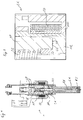
- Figure 1 shows a fluid injector 1 that is particularly suitable for dosing fuel to an internal combustion engine.
- the fluid injector 1 may be provided for dosing the fuel into an intake manifold of the internal combustion engine or, preferably, for dosing the fuel directly into a combustion chamber of the internal combustion engine.
- the injector 1 has a central longitudinal axis LA and an injection valve housing HO with an injection valve cavity CA.
- the injection valve cavity CA extends along the longitudinal axis LA from a fluid inlet portion to a fluid outlet portion and hydraulically couples a fluid inlet to a fluid outlet of the injector 1.
- the injection valve cavity CA takes in a valve needle VN.
- the valve needle VN is axially movable within the injection valve cavity CA with respect to the injection valve housing HO.
- the injector 1 further comprises a valve seat VS, on which the valve needle VN rests in a closed position and from which the valve needle VN is axially displaced towards an open position for dispensing fluid from the injector 1.
- the injector 1 further comprises a spring element SE being designed and arranged to exert a force on the valve needle VN acting to urge the valve needle VN in a closed position.
- a spring element SE being designed and arranged to exert a force on the valve needle VN acting to urge the valve needle VN in a closed position.
- the valve needle VN sealingly rests on the valve seat VS, by this preventing fluid flow through at least one injection nozzle which is in particular comprised by the valve seat VS and represents the fluid outlet of the injector 1.
- the injection nozzle may be, for example, an injection hole. However, it may also be of some other type suitable for dosing fluid.
- the injector 1 further comprises an inlet tube IT in which a component CP is arranged.
- the component CP forms a seat for the spring element SE.
- the component CP can be axially moved in the inlet tube IT in order to adjust the force of the spring element SE in a desired manner.
- the injector 1 further comprises an electromagnetic actuator unit EA, which is being designed to actuate the valve needle VN.
- the electromagnetic actuator unit EA which is shown in Figure 2 , comprises a coil CO. It further comprises a pole piece PP which is fixedly coupled with respect to the injection valve housing HO.
- the electromagnetic actuator unit EA further comprises an armature AR which is axially movable within the injection valve cavity CA and operable to displace the valve needle VN axially away from the closed position towards the open position.
- the armature AR may be fixedly mechanically coupled to the valve needle VN or even in one piece with the valve needle VN.
- the present embodiment is axially displaceable with respect to the valve needle VN, wherein axial displacement of the armature AR with respect to the valve needle VN in the direction away from the valve seat VS is limited by a retainer which is fixed to the valve needle VN.
- the retainer is also operable to guide the valve needle VN in axial direction by means of mechanical interaction with the pole piece PP.
- the armature AR is operable to take the valve needle VN with it in direction away from the closed position by means of mechanical interaction via the retainer. In the direction towards the valve seat VS, axial displacement of the armature AR with respect to the valve needle VN is limited by means of a disc element which is fixed to the valve needle VN.
- the pole piece PP has a first contact surface CS1 and the armature AR has a second contact surface CS2.
- the first and the second contact surface CS1, CS2 are directed opposite to each other, i.e. the first and second surfaces CS1, CS2 face towards each other.
- the pole piece PP is operable to limit axial displacement of the armature AR with respect to the injection valve housing HO by means of interaction of the first and second contact surfaces CS1, CS2, in particular - and disregarding a possible fluid film remaining between the two contact surfaces CS1, CS2 when the fluid injector 1 is in operation - by means of a form-fit engagement of the first and second contact surfaces CS1, CS2.
- One of the two contact surfaces CS1, CS2 is designed to have a contact angle ⁇ with a given fluid, which is smaller than 90°.
- the other of the two contact surfaces CS1, CS2 is designed to have a contact angle ⁇ with the given fluid, which is 90° or larger.
- the second contact surface CS2 of the armature AR can, for example be arranged on a step.
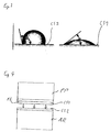
- the contact angle ⁇ is exemplary shown in Figure 3 .
- the contact angle ⁇ is the angle between a surface and a liquid drop of a given fluid.
- the contact angle ⁇ is, for example, defined by Young's equation.
- the contact angle ⁇ of the second contact surface CS2 is larger than 90°, thus the contact surface CS2 is fluid-phobic.
- the contact angle ⁇ of contact surface CS1 is smaller than 90°, thus the contact surface CS1 is fluid-philic.
- the fluid is, for example, gasoline or diesel.
- the fluid is led from the fluid inlet portion towards the fluid outlet portion through the injection valve cavity CA.
- valve needle VN prevents a fluid flow through the fluid outlet and out of the injection valve housing HO in the closed position of the valve needle VN. Outside of the closed position of the valve needle VN, the valve needle VN unseals the injection nozzle to enable the fluid flow through the fuel outlet.
- the electromagnetic actuator unit EA may effect an electromagnetic force on the armature AR.
- the armature AR may move in a direction away from the fuel outlet portion, in particular upstream of a fluid flow, due to the electromagnetic force acting on the armature AR.
- the armature AR may take the valve needle VN with it, such that the valve needle VN moves in axial direction out of the closed position.
- a gap between the valve seat VS and the valve needle VN at an axial end of the valve needle VN facing away from the electromagnetic actuator unit EA forms a fluid path and fluid can pass through the injection nozzle.
- the contact surface CS1 of the pole piece PP could get in contact with the contact surface CS2 of the armature AR. Due to the fact that one of the contact surfaces CS1, CS2 is fluid-philic and the other is fluid-phobic, a wetting film FL (see figure 4 ) is generated, which causes a damping effect. In this way, a sticking effect of the injector 1 can be reduced so that in particular an advantageously short closing transient of the injector is achievable. Also, the risk of degradation of the injector due to wearing at the first and second contact surfaces CS1, CS2, is reduced. In this way, changes of the injector behavior over its lifetime may be particularly small.
- the force balance between the force on the valve needle VN caused by the electromagnetic actuator unit EA with the coil CO and the force on the valve needle VN caused by the spring element SE is chosen in such fasion that the spring element SE may force the valve needle VN to move in axial direction in its closed position when the electromagnetic actuator unit EA is de-energized.
- the fluid-philic attribute of one contact surface can, for example, be achieved by a suitable surface structure, for example by small recesses, which, for example, are produced by laser scattering.
- the fluid-philic attribute can be achieved with an oxidation coating, which is for example produced by plasma ionisation.
- the fluid-philic attribute can be achieved with a coating with a suitable material with a thickness between 10 nm and 1000 nm.
- the fluid-phobic attribute of one contact surface can, for example, be achieved by a suitable surface structure, for example by small bumps and/or pins, which, for example, are produced by laser scattering.
- the fluid-phobic attribute can be achieved with an oxidation coating, which is for example produced by plasma ionisation.
- the fluid-phobic attribute can be achieved with a coating with a suitable material with a thickness between 10 nm and 1000 nm.
Landscapes
- Engineering & Computer Science (AREA)
- Chemical & Material Sciences (AREA)
- Combustion & Propulsion (AREA)
- Mechanical Engineering (AREA)
- General Engineering & Computer Science (AREA)
- Physics & Mathematics (AREA)
- Electromagnetism (AREA)
- Fuel-Injection Apparatus (AREA)
Description
- The invention relates to a fluid injector for a combustion engine.
- Injectors are in widespread use, in particular for internal combustion engines, where they may be arranged in order to dose the fluid into an intake manifold of the internal combustion engine or directly into the combustion chamber of a cylinder of the internal combustion engine. These injectors ought to have a high reliability over their lifetime and a very exact injection volume.
-
US 2009/159728 A1 discloses a fuel injection valve which has a valve guide, a valve member movable in a center opening of the valve guide along an axial direction of the valve guide, and a covering layer disposed on a surface of the valve guide. The valve guide has a valve seat placed on an inner surface thereof and a nozzle hole from which fuel is injected. The valve member is seated on the valve seat to close the nozzle hole and leaves the valve seat to open the nozzle hole. The covering layer is placed around an outlet opening of the nozzle hole. The covering layer is made of boron nitride in a hexagonal crystal system so as to have a hydrophilic property higher than that of the surface of the valve guide. -
US 4,245,789 A relates to an electromagnetic fuel injector wherein at least one and preferably the physically softer one of the opposed working air gap surface of the pole piece and armature of the injector solenoid assembly has a roughened surface texture thereon with an average surface roughness rating value of the order of 16 to 32 microinches. - It is an object of the invention to specify an injector which has little wearing.
- This object is achieved by a fluid injector having the features of the independent claim. Advantageous embodiments of the invention are given in the sub-claims.
- A fluid injector for a combustion engine, in particular for an internal combustion engine, is specified. The fluid injector has a central longitudinal axis and comprises an injection valve housing with an injection valve cavity. The injector further comprises a valve needle being axially movable within the injection valve cavity. The injector comprises an electromagnetic actuator unit being operable to actuate the valve needle. The electromagnetic actuator unit comprises a pole piece and an armature. The pole piece is fixedly coupled with respect to the injection valve housing or in one piece with the injection valve housing. The armature is axially movable within the injection valve cavity and operable to displace the valve needle axially. The armature may be fixedly mechanically coupled to the valve needle. Alternatively it may axially displaceable with respect to the valve needle, wherein axial displacement of the armature with respect to the valve needle is expediently limited, for example by a retainer integrated in the valve needle of fixed to the valve needle.
- The pole piece has a first contact surface and the armature has a second contact surface, which are directed opposite to each other. In other words, the first and second contact surfaces face towards one another. The pole piece may be operable to limit axial displacement of the armature with respect to the injection valve housing by means of mechanical interaction of the first and second contact surfaces, in particular by means of a form-fit engagement of the first and second contact surfaces. One of the two contact surfaces is designed to have a contact angle with a given fluid, which is smaller than 90° and the other of the two contact surfaces is designed to have a contact angle with the given fluid, which is 90° or larger.
- The given fluid is, for example, gasoline or diesel. The contact surface, which is designed to have a contact angle with the given fluid, which is smaller than 90°, can also be called a fluid-philic - e.g gasoline-philic or diesel-philic - contact surface. The contact surface, which is designed to have a contact angle with the given fluid, which is 90° or larger, can also be called a fluid-phobic - e.g gasoline-phobic or diesel-phobic -contact surface.
- The contact angle is the angle between the contact surface and a liquid drop of the given fluid. The contact angle is, for example, defined by Young's equation. The smaller the contact angle is the stronger is the effect of the fluid-philic contact surface. The bigger the contact angle is the stronger is the effect of the fluid-phobic contact surface. Therefore the fluid-philic contact surface has, for example, a very small contact angle near 0° and the fluid-phobic contact surface has, for example, a very large contact angle of 120° to 160°.
- The fluid-philic contact surface can also have a higher adhesiveness and/or a higher wetting ability and/or a higher surface energy than the fluid-phobic contact surface.
- By the fluid-philic attribute a wetting film is created during operation of the injector on the fluid-philic contact surface. The wetting film acts as a damping element, by which wearing is reduced. This effect is increased by the fluid-phobic contact surface, because the fluid is pushed away by the fluid-phobic contact surface in the direction of the fluid-philic contact surface. Due to this pushing effect also a sticking effect between the two contact surfaces can be reduced. Further, because the wetting film reduces wearing and can be used as a distance element between the two contact surfaces, there is no need to use toxic chrome, which is normally used as a distance element and for reducing wearing. Thus a chrome-free injector can be achieved.
- According to one embodiment, the contact surface, which is designed to have a contact angle with the given fluid, which is 90° or larger, comprises small bumps. In particular, the contact surface is provided with the fluid-phobic properties by means of the small bumps.
- The lateral dimensions of the bumps are, for example, in a range between 1 µm and 30 µm, in particular between 5 µm and 20 µm, where the limits are included in each case. The height of the bumps may be in the same ranges. In another embodiment, the height of the bumps is in a range between 10 nm and 1000 nm, the limits being included. The small bumps have, for example, a diameter of about 10 µm. The small bumps are, for example, produced by laser scattering. With such small bumps and/or pins very high contact angles can be achieved.
- According to a further embodiment, the contact surface, which is designed to have a contact angle with the given fluid, which is smaller than 90°, comprises small recesses. In particular, the contact surface is provided with the fluid-philic properties by means of the small recesses.
- The lateral dimensions of the recesses are, for example, in a range between 1 µm and 30 µm, in particular between 5 µm and 20 µm, where the limits are included in each case. The depth of the recesses may be in the same ranges. In another embodiment, the depth of the recesses is in a range between 10 nm and 1000 nm, the limits being included. The small recesses have, for example, a diameter of 10 µm. The small recesses are, for example, made by laser scattering. With such small recesses very small contact angles can be achieved.
- According to a further embodiment, the contact surface, which is designed to have a contact angle with the given fluid, which is smaller than 90°, is comprised by an oxidation coated contact region of the armature or the pole piece, respectively.
- The oxidation coating is, for example, made by plasma ionization. With the oxidation coating a number of functional polar regions of the surface can be increased or decreased. This results in a modified surface energy of the contact surface. With this feature very small contact angles can be achieved.
- According to a further embodiment, the contact surface, which is designed to have a contact angle with the given fluid, which is 90° or larger, is comprised by an oxidation coated contact region of the armature or the pole piece, respectively.
- The oxidation coating of the contact region is, for example, made by plasma ionization. With the oxidation coating a number of functional polar regions of the surface can be increased or decreased. This results in a modified surface energy of the contact surface. With this feature very large contact angles can be achieved.
- Methods for modifying the surface energy by means of oxidation coating to achieve fluid-philic or fluid-phobic properties, respectively, are in principle known to the skilled person and, therefore, are not explained in further detail here.
- According to a further embodiment, the contact surface, which is designed to have a contact angle with the given fluid, which is smaller than 90°, is comprised by a coating of the pole piece or the armature, respectively, with a thickness between 10 nm and 1000 nm.
- By this kind of nano-coating with a suitable material, for example PTFE, very small contact angles can be achieved with a particularly thin coating film.
- According to a further embodiment, the contact surface, which is designed to have a contact angle with the given fluid, which is 90° or larger, is comprised by a coating of the pole piece or the armature, respectively, with a thickness between 10 nm and 1000 nm.
- By this kind of nano-coating with a suitable material, for example PTFE, very large contact angles can be achieved with a particularly thin coating film.
- In one embodiment, the bumps and/or recesses may be comprised by the respective coating.
- Exemplary embodiments of the invention are explained in the following with the aid of schematic drawings. These are as follows:
- Figure 1
- a fluid injector according to an exemplary embodiment in a longitudinal section view,
- Figure 2
- an enlarged section of an electromagnetic actuator unit of the injector,
- Figure 3
- an example of contact angles and
- Figure 4
- an enlarged view of two contact surfaces of the injector.
-
Figure 1 shows afluid injector 1 that is particularly suitable for dosing fuel to an internal combustion engine. Thefluid injector 1 may be provided for dosing the fuel into an intake manifold of the internal combustion engine or, preferably, for dosing the fuel directly into a combustion chamber of the internal combustion engine. - The
injector 1 has a central longitudinal axis LA and an injection valve housing HO with an injection valve cavity CA. The injection valve cavity CA extends along the longitudinal axis LA from a fluid inlet portion to a fluid outlet portion and hydraulically couples a fluid inlet to a fluid outlet of theinjector 1. - The injection valve cavity CA takes in a valve needle VN. The valve needle VN is axially movable within the injection valve cavity CA with respect to the injection valve housing HO. The
injector 1 further comprises a valve seat VS, on which the valve needle VN rests in a closed position and from which the valve needle VN is axially displaced towards an open position for dispensing fluid from theinjector 1. - The
injector 1 further comprises a spring element SE being designed and arranged to exert a force on the valve needle VN acting to urge the valve needle VN in a closed position. In the closed position of the valve needle VN, the valve needle VN sealingly rests on the valve seat VS, by this preventing fluid flow through at least one injection nozzle which is in particular comprised by the valve seat VS and represents the fluid outlet of theinjector 1. The injection nozzle may be, for example, an injection hole. However, it may also be of some other type suitable for dosing fluid. - The
injector 1 further comprises an inlet tube IT in which a component CP is arranged. The component CP forms a seat for the spring element SE. During a manufacturing process of theinjector 1, the component CP can be axially moved in the inlet tube IT in order to adjust the force of the spring element SE in a desired manner. - The
injector 1 further comprises an electromagnetic actuator unit EA, which is being designed to actuate the valve needle VN. The electromagnetic actuator unit EA, which is shown inFigure 2 , comprises a coil CO. It further comprises a pole piece PP which is fixedly coupled with respect to the injection valve housing HO. The electromagnetic actuator unit EA further comprises an armature AR which is axially movable within the injection valve cavity CA and operable to displace the valve needle VN axially away from the closed position towards the open position. The armature AR may be fixedly mechanically coupled to the valve needle VN or even in one piece with the valve needle VN. In the present embodiment, it is axially displaceable with respect to the valve needle VN, wherein axial displacement of the armature AR with respect to the valve needle VN in the direction away from the valve seat VS is limited by a retainer which is fixed to the valve needle VN. The retainer is also operable to guide the valve needle VN in axial direction by means of mechanical interaction with the pole piece PP. The armature AR is operable to take the valve needle VN with it in direction away from the closed position by means of mechanical interaction via the retainer. In the direction towards the valve seat VS, axial displacement of the armature AR with respect to the valve needle VN is limited by means of a disc element which is fixed to the valve needle VN. - The pole piece PP has a first contact surface CS1 and the armature AR has a second contact surface CS2. The first and the second contact surface CS1, CS2 are directed opposite to each other, i.e. the first and second surfaces CS1, CS2 face towards each other. The pole piece PP is operable to limit axial displacement of the armature AR with respect to the injection valve housing HO by means of interaction of the first and second contact surfaces CS1, CS2, in particular - and disregarding a possible fluid film remaining between the two contact surfaces CS1, CS2 when the
fluid injector 1 is in operation - by means of a form-fit engagement of the first and second contact surfaces CS1, CS2. One of the two contact surfaces CS1, CS2 is designed to have a contact angle θ with a given fluid, which is smaller than 90°. The other of the two contact surfaces CS1, CS2 is designed to have a contact angle θ with the given fluid, which is 90° or larger. The second contact surface CS2 of the armature AR can, for example be arranged on a step. - The contact angle θ is exemplary shown in
Figure 3 . The contact angle θ is the angle between a surface and a liquid drop of a given fluid. The contact angle θ is, for example, defined by Young's equation. InFigure 3 the contact angle θ of the second contact surface CS2 is larger than 90°, thus the contact surface CS2 is fluid-phobic. The contact angle θ of contact surface CS1 is smaller than 90°, thus the contact surface CS1 is fluid-philic. The fluid is, for example, gasoline or diesel. - In the following the function of the
injector 1 is described in detail:
The fluid is led from the fluid inlet portion towards the fluid outlet portion through the injection valve cavity CA. - The valve needle VN prevents a fluid flow through the fluid outlet and out of the injection valve housing HO in the closed position of the valve needle VN. Outside of the closed position of the valve needle VN, the valve needle VN unseals the injection nozzle to enable the fluid flow through the fuel outlet.
- In case that the electromagnetic actuator unit EA with the coil CO gets energized, the electromagnetic actuator unit EA may effect an electromagnetic force on the armature AR. The armature AR may move in a direction away from the fuel outlet portion, in particular upstream of a fluid flow, due to the electromagnetic force acting on the armature AR. Due to the mechanical coupling with the valve needle VN, the armature AR may take the valve needle VN with it, such that the valve needle VN moves in axial direction out of the closed position. Outside of the closed position of the valve needle VN a gap between the valve seat VS and the valve needle VN at an axial end of the valve needle VN facing away from the electromagnetic actuator unit EA forms a fluid path and fluid can pass through the injection nozzle.
- In case that the electromagnetic actuator unit EA gets energized, the contact surface CS1 of the pole piece PP could get in contact with the contact surface CS2 of the armature AR. Due to the fact that one of the contact surfaces CS1, CS2 is fluid-philic and the other is fluid-phobic, a wetting film FL (see
figure 4 ) is generated, which causes a damping effect. In this way, a sticking effect of theinjector 1 can be reduced so that in particular an advantageously short closing transient of the injector is achievable. Also, the risk of degradation of the injector due to wearing at the first and second contact surfaces CS1, CS2, is reduced. In this way, changes of the injector behavior over its lifetime may be particularly small. - The force balance between the force on the valve needle VN caused by the electromagnetic actuator unit EA with the coil CO and the force on the valve needle VN caused by the spring element SE is chosen in such fasion that the spring element SE may force the valve needle VN to move in axial direction in its closed position when the electromagnetic actuator unit EA is de-energized.
- The fluid-philic attribute of one contact surface (CS1, CS2) can, for example, be achieved by a suitable surface structure, for example by small recesses, which, for example, are produced by laser scattering. Alternatively or additionally the fluid-philic attribute can be achieved with an oxidation coating, which is for example produced by plasma ionisation. Alternative or additional the fluid-philic attribute can be achieved with a coating with a suitable material with a thickness between 10 nm and 1000 nm.
- The fluid-phobic attribute of one contact surface (CS1, CS2) can, for example, be achieved by a suitable surface structure, for example by small bumps and/or pins, which, for example, are produced by laser scattering. Alternatively or additionally the fluid-phobic attribute can be achieved with an oxidation coating, which is for example produced by plasma ionisation. Alternative or additional the fluid-phobic attribute can be achieved with a coating with a suitable material with a thickness between 10 nm and 1000 nm.
Claims (9)
- Fluid injector (1) for a combustion engine comprising:a central longitudinal axis (LA),an injection valve housing (HO) with an injection valve cavity (CA),a valve needle (VN) being axially movable within the injection valve cavity (CA),an electromagnetic actuator unit (EA) being designed to actuate the valve needle (VN), the electromagnetic actuator unit (EA) comprising a pole piece (PP) being fixedly coupled to the injection valve housing (HO) and an armature (AR) being axially movable within the injection valve cavity (CA) and operable to displace the valve needle (VN),wherein the pole piece (PP) has a first contact surface (CS1) and the armature (AR) has a second contact surface (CS2) which are directed opposite to each other, wherein one of the two contact surfaces (CS1, CS2) is designed to have a contact angle (θ) with a given fluid, which is smaller than 90° andwherein the other of the two contact surfaces (CS1, CS2) is designed to have a contact angle (θ) with the given fluid, which is 90° or larger.
- Injector (1) according to claim 1, wherein the contact surface (CS1, CS2), which is designed to have a contact angle (θ) with the given fluid, which is 90° or larger, comprises small bumps.
- Injector according to claim 2, wherein the bumps have lateral dimensions between 1 µm and 30 µm.
- Injector (1) according to any one of the preceding claims, wherein the contact surface (CS1, CS2), which is designed to have a contact angle (θ) with the given fluid, which is smaller than 90°, comprises small recesses.
- Injector according to claim 4, wherein the recesses have lateral dimensions between 1 µm and 30 µm.
- Injector (1) according to any one of the preceding claims, wherein the contact surface (CS1, CS2), which is designed to have a contact angle (θ) with the given fluid, which is smaller than 90°, is comprised by an oxidation coated contact region of the pole piece (PP) or the armature (AR), respectively.
- Injector (1) according to any one of the preceding claims, wherein the contact surface (CS1, CS2), which is designed to have a contact angle (θ) with the given fluid, which is 90° or larger, is comprised by an oxidation coated contact region of the pole piece (PP) or the armature (AR), respectively.
- Injector (1) according to any of the claims 1 to 5, wherein the contact surface (CS1, CS2), which is designed to have a contact angle (θ) with the given fluid, which is smaller than 90°, is comprised by a coating of the pole piece (PP) or the armature (AR), respectively, with a thickness between 10 nm and 1000 nm.
- Injector (1) according to any of the preceding claims, wherein the contact surface (CS1, CS2), which is designed to have a contact angle (θ) with the given fluid, which is 90° or larger, is comprised by a coating of the pole piece (PP) or the armature (AR), respectively, with a thickness between 10 nm and 1000 nm.
Priority Applications (4)
| Application Number | Priority Date | Filing Date | Title |
|---|---|---|---|
| EP13170450.4A EP2811148B1 (en) | 2013-06-04 | 2013-06-04 | Fluid injector for a combustion engine |
| KR1020140067653A KR102113991B1 (en) | 2013-06-04 | 2014-06-03 | Fluid injector for a combustion engine |
| CN201410244019.0A CN104214033B (en) | 2013-06-04 | 2014-06-04 | Fluid ejector for combustion engine |
| US14/295,604 US9551290B2 (en) | 2013-06-04 | 2014-06-04 | Fluid injector for a combustion engine |
Applications Claiming Priority (1)
| Application Number | Priority Date | Filing Date | Title |
|---|---|---|---|
| EP13170450.4A EP2811148B1 (en) | 2013-06-04 | 2013-06-04 | Fluid injector for a combustion engine |
Publications (2)
| Publication Number | Publication Date |
|---|---|
| EP2811148A1 EP2811148A1 (en) | 2014-12-10 |
| EP2811148B1 true EP2811148B1 (en) | 2016-03-23 |
Family
ID=48537875
Family Applications (1)
| Application Number | Title | Priority Date | Filing Date |
|---|---|---|---|
| EP13170450.4A Active EP2811148B1 (en) | 2013-06-04 | 2013-06-04 | Fluid injector for a combustion engine |
Country Status (4)
| Country | Link |
|---|---|
| US (1) | US9551290B2 (en) |
| EP (1) | EP2811148B1 (en) |
| KR (1) | KR102113991B1 (en) |
| CN (1) | CN104214033B (en) |
Families Citing this family (1)
| Publication number | Priority date | Publication date | Assignee | Title |
|---|---|---|---|---|
| KR102119988B1 (en) * | 2015-10-15 | 2020-06-17 | 콘티넨탈 오토모티브 게엠베하 | Fuel injection valve with anti-skid device, combustion engine and vehicle |
Family Cites Families (9)
| Publication number | Priority date | Publication date | Assignee | Title |
|---|---|---|---|---|
| US3814598A (en) * | 1970-12-29 | 1974-06-04 | Chromalloy American Corp | Wear resistant powder metal magnetic pole piece made from oxide coated fe-al-si powders |
| US4245789A (en) * | 1979-05-03 | 1981-01-20 | General Motors Corporation | Electromagnetic fuel injector |
| CN1049951C (en) * | 1993-12-09 | 2000-03-01 | 罗伯特·博施有限公司 | Electromagnetic valve |
| JP4225297B2 (en) * | 2005-06-29 | 2009-02-18 | トヨタ自動車株式会社 | Fuel injection valve for internal combustion engine |
| JP2007205234A (en) * | 2006-02-01 | 2007-08-16 | Denso Corp | Fuel injection valve |
| JP4492696B2 (en) * | 2007-12-25 | 2010-06-30 | 株式会社デンソー | Fuel injection valve |
| JP4811476B2 (en) * | 2009-03-05 | 2011-11-09 | 株式会社デンソー | Water repellent layer forming method for forming water repellent layer and fuel injection valve having water repellent layer |
| JP5178683B2 (en) * | 2009-10-21 | 2013-04-10 | 日立オートモティブシステムズ株式会社 | Electromagnetic fuel injection valve |
| JP2013072298A (en) * | 2011-09-27 | 2013-04-22 | Hitachi Automotive Systems Ltd | Fuel injection valve |
-
2013
- 2013-06-04 EP EP13170450.4A patent/EP2811148B1/en active Active
-
2014
- 2014-06-03 KR KR1020140067653A patent/KR102113991B1/en not_active Expired - Fee Related
- 2014-06-04 CN CN201410244019.0A patent/CN104214033B/en active Active
- 2014-06-04 US US14/295,604 patent/US9551290B2/en active Active
Also Published As
| Publication number | Publication date |
|---|---|
| CN104214033A (en) | 2014-12-17 |
| US9551290B2 (en) | 2017-01-24 |
| CN104214033B (en) | 2018-04-13 |
| EP2811148A1 (en) | 2014-12-10 |
| KR20140142673A (en) | 2014-12-12 |
| US20140352667A1 (en) | 2014-12-04 |
| KR102113991B1 (en) | 2020-05-25 |
Similar Documents
| Publication | Publication Date | Title |
|---|---|---|
| EP2436910B1 (en) | Valve assembly for an injection valve and injection valve | |
| EP2535552B1 (en) | Valve assembly for an injection valve and injection valve | |
| CN103890370B (en) | Valve assemblies and injection valves for injection valves | |
| EP2852753B1 (en) | Valve assembly for an injection valve and injection valve | |
| EP1783356B1 (en) | Fuel injector | |
| US8919372B2 (en) | Valve assembly for an injection valve and injection valve | |
| US7909270B2 (en) | Valve assembly for an injection valve and injection valve | |
| US20150260138A1 (en) | Valve Assembly for an Injection Valve and Injection Valve | |
| EP2863045B1 (en) | Method of fabricating an injector for a combustion engine, armature-needle assembly and fluid injector | |
| CN104583576A (en) | Valve assemblies and injection valves for injection valves | |
| EP2811148B1 (en) | Fluid injector for a combustion engine | |
| JP5838107B2 (en) | Fuel injection valve | |
| US7607636B2 (en) | Valve assembly for an injection valve and injection valve | |
| EP2719886B1 (en) | Valve assembly for an injection valve | |
| EP2568155B1 (en) | Valve assembly and injection valve | |
| EP3009658B1 (en) | Injector for injecting fluid | |
| EP2426350A1 (en) | Valve assembly for an injection valve and injection valve | |
| EP2241743B1 (en) | Valve assembly for an injection valve and injection valve |
Legal Events
| Date | Code | Title | Description |
|---|---|---|---|
| PUAI | Public reference made under article 153(3) epc to a published international application that has entered the european phase |
Free format text: ORIGINAL CODE: 0009012 |
|
| 17P | Request for examination filed |
Effective date: 20130604 |
|
| AK | Designated contracting states |
Kind code of ref document: A1 Designated state(s): AL AT BE BG CH CY CZ DE DK EE ES FI FR GB GR HR HU IE IS IT LI LT LU LV MC MK MT NL NO PL PT RO RS SE SI SK SM TR |
|
| AX | Request for extension of the european patent |
Extension state: BA ME |
|
| R17P | Request for examination filed (corrected) |
Effective date: 20150610 |
|
| RBV | Designated contracting states (corrected) |
Designated state(s): AL AT BE BG CH CY CZ DE DK EE ES FI FR GB GR HR HU IE IS IT LI LT LU LV MC MK MT NL NO PL PT RO RS SE SI SK SM TR |
|
| GRAP | Despatch of communication of intention to grant a patent |
Free format text: ORIGINAL CODE: EPIDOSNIGR1 |
|
| RIC1 | Information provided on ipc code assigned before grant |
Ipc: F02M 51/06 20060101AFI20150831BHEP Ipc: F02M 61/18 20060101ALI20150831BHEP Ipc: F02M 61/16 20060101ALI20150831BHEP |
|
| INTG | Intention to grant announced |
Effective date: 20151001 |
|
| GRAS | Grant fee paid |
Free format text: ORIGINAL CODE: EPIDOSNIGR3 |
|
| GRAA | (expected) grant |
Free format text: ORIGINAL CODE: 0009210 |
|
| AK | Designated contracting states |
Kind code of ref document: B1 Designated state(s): AL AT BE BG CH CY CZ DE DK EE ES FI FR GB GR HR HU IE IS IT LI LT LU LV MC MK MT NL NO PL PT RO RS SE SI SK SM TR |
|
| REG | Reference to a national code |
Ref country code: GB Ref legal event code: FG4D |
|
| REG | Reference to a national code |
Ref country code: CH Ref legal event code: EP |
|
| REG | Reference to a national code |
Ref country code: AT Ref legal event code: REF Ref document number: 783423 Country of ref document: AT Kind code of ref document: T Effective date: 20160415 |
|
| REG | Reference to a national code |
Ref country code: IE Ref legal event code: FG4D |
|
| REG | Reference to a national code |
Ref country code: DE Ref legal event code: R096 Ref document number: 602013005643 Country of ref document: DE |
|
| REG | Reference to a national code |
Ref country code: FR Ref legal event code: PLFP Year of fee payment: 4 |
|
| REG | Reference to a national code |
Ref country code: LT Ref legal event code: MG4D |
|
| REG | Reference to a national code |
Ref country code: NL Ref legal event code: MP Effective date: 20160323 |
|
| PG25 | Lapsed in a contracting state [announced via postgrant information from national office to epo] |
Ref country code: NO Free format text: LAPSE BECAUSE OF FAILURE TO SUBMIT A TRANSLATION OF THE DESCRIPTION OR TO PAY THE FEE WITHIN THE PRESCRIBED TIME-LIMIT Effective date: 20160623 Ref country code: HR Free format text: LAPSE BECAUSE OF FAILURE TO SUBMIT A TRANSLATION OF THE DESCRIPTION OR TO PAY THE FEE WITHIN THE PRESCRIBED TIME-LIMIT Effective date: 20160323 Ref country code: FI Free format text: LAPSE BECAUSE OF FAILURE TO SUBMIT A TRANSLATION OF THE DESCRIPTION OR TO PAY THE FEE WITHIN THE PRESCRIBED TIME-LIMIT Effective date: 20160323 |
|
| REG | Reference to a national code |
Ref country code: AT Ref legal event code: MK05 Ref document number: 783423 Country of ref document: AT Kind code of ref document: T Effective date: 20160323 |
|
| PG25 | Lapsed in a contracting state [announced via postgrant information from national office to epo] |
Ref country code: LT Free format text: LAPSE BECAUSE OF FAILURE TO SUBMIT A TRANSLATION OF THE DESCRIPTION OR TO PAY THE FEE WITHIN THE PRESCRIBED TIME-LIMIT Effective date: 20160323 Ref country code: SE Free format text: LAPSE BECAUSE OF FAILURE TO SUBMIT A TRANSLATION OF THE DESCRIPTION OR TO PAY THE FEE WITHIN THE PRESCRIBED TIME-LIMIT Effective date: 20160323 Ref country code: NL Free format text: LAPSE BECAUSE OF FAILURE TO SUBMIT A TRANSLATION OF THE DESCRIPTION OR TO PAY THE FEE WITHIN THE PRESCRIBED TIME-LIMIT Effective date: 20160323 Ref country code: RS Free format text: LAPSE BECAUSE OF FAILURE TO SUBMIT A TRANSLATION OF THE DESCRIPTION OR TO PAY THE FEE WITHIN THE PRESCRIBED TIME-LIMIT Effective date: 20160323 Ref country code: LV Free format text: LAPSE BECAUSE OF FAILURE TO SUBMIT A TRANSLATION OF THE DESCRIPTION OR TO PAY THE FEE WITHIN THE PRESCRIBED TIME-LIMIT Effective date: 20160323 |
|
| PG25 | Lapsed in a contracting state [announced via postgrant information from national office to epo] |
Ref country code: PL Free format text: LAPSE BECAUSE OF FAILURE TO SUBMIT A TRANSLATION OF THE DESCRIPTION OR TO PAY THE FEE WITHIN THE PRESCRIBED TIME-LIMIT Effective date: 20160323 Ref country code: IS Free format text: LAPSE BECAUSE OF FAILURE TO SUBMIT A TRANSLATION OF THE DESCRIPTION OR TO PAY THE FEE WITHIN THE PRESCRIBED TIME-LIMIT Effective date: 20160723 Ref country code: EE Free format text: LAPSE BECAUSE OF FAILURE TO SUBMIT A TRANSLATION OF THE DESCRIPTION OR TO PAY THE FEE WITHIN THE PRESCRIBED TIME-LIMIT Effective date: 20160323 |
|
| PG25 | Lapsed in a contracting state [announced via postgrant information from national office to epo] |
Ref country code: SK Free format text: LAPSE BECAUSE OF FAILURE TO SUBMIT A TRANSLATION OF THE DESCRIPTION OR TO PAY THE FEE WITHIN THE PRESCRIBED TIME-LIMIT Effective date: 20160323 Ref country code: SM Free format text: LAPSE BECAUSE OF FAILURE TO SUBMIT A TRANSLATION OF THE DESCRIPTION OR TO PAY THE FEE WITHIN THE PRESCRIBED TIME-LIMIT Effective date: 20160323 Ref country code: RO Free format text: LAPSE BECAUSE OF FAILURE TO SUBMIT A TRANSLATION OF THE DESCRIPTION OR TO PAY THE FEE WITHIN THE PRESCRIBED TIME-LIMIT Effective date: 20160323 Ref country code: PT Free format text: LAPSE BECAUSE OF FAILURE TO SUBMIT A TRANSLATION OF THE DESCRIPTION OR TO PAY THE FEE WITHIN THE PRESCRIBED TIME-LIMIT Effective date: 20160725 Ref country code: AT Free format text: LAPSE BECAUSE OF FAILURE TO SUBMIT A TRANSLATION OF THE DESCRIPTION OR TO PAY THE FEE WITHIN THE PRESCRIBED TIME-LIMIT Effective date: 20160323 Ref country code: CZ Free format text: LAPSE BECAUSE OF FAILURE TO SUBMIT A TRANSLATION OF THE DESCRIPTION OR TO PAY THE FEE WITHIN THE PRESCRIBED TIME-LIMIT Effective date: 20160323 Ref country code: ES Free format text: LAPSE BECAUSE OF FAILURE TO SUBMIT A TRANSLATION OF THE DESCRIPTION OR TO PAY THE FEE WITHIN THE PRESCRIBED TIME-LIMIT Effective date: 20160323 |
|
| PG25 | Lapsed in a contracting state [announced via postgrant information from national office to epo] |
Ref country code: BE Free format text: LAPSE BECAUSE OF FAILURE TO SUBMIT A TRANSLATION OF THE DESCRIPTION OR TO PAY THE FEE WITHIN THE PRESCRIBED TIME-LIMIT Effective date: 20160323 |
|
| REG | Reference to a national code |
Ref country code: DE Ref legal event code: R097 Ref document number: 602013005643 Country of ref document: DE |
|
| PLBE | No opposition filed within time limit |
Free format text: ORIGINAL CODE: 0009261 |
|
| STAA | Information on the status of an ep patent application or granted ep patent |
Free format text: STATUS: NO OPPOSITION FILED WITHIN TIME LIMIT |
|
| PG25 | Lapsed in a contracting state [announced via postgrant information from national office to epo] |
Ref country code: MC Free format text: LAPSE BECAUSE OF FAILURE TO SUBMIT A TRANSLATION OF THE DESCRIPTION OR TO PAY THE FEE WITHIN THE PRESCRIBED TIME-LIMIT Effective date: 20160323 Ref country code: DK Free format text: LAPSE BECAUSE OF FAILURE TO SUBMIT A TRANSLATION OF THE DESCRIPTION OR TO PAY THE FEE WITHIN THE PRESCRIBED TIME-LIMIT Effective date: 20160323 |
|
| REG | Reference to a national code |
Ref country code: CH Ref legal event code: PL |
|
| PG25 | Lapsed in a contracting state [announced via postgrant information from national office to epo] |
Ref country code: BG Free format text: LAPSE BECAUSE OF FAILURE TO SUBMIT A TRANSLATION OF THE DESCRIPTION OR TO PAY THE FEE WITHIN THE PRESCRIBED TIME-LIMIT Effective date: 20160623 |
|
| 26N | No opposition filed |
Effective date: 20170102 |
|
| REG | Reference to a national code |
Ref country code: IE Ref legal event code: MM4A |
|
| PG25 | Lapsed in a contracting state [announced via postgrant information from national office to epo] |
Ref country code: CH Free format text: LAPSE BECAUSE OF NON-PAYMENT OF DUE FEES Effective date: 20160630 Ref country code: LI Free format text: LAPSE BECAUSE OF NON-PAYMENT OF DUE FEES Effective date: 20160630 |
|
| PG25 | Lapsed in a contracting state [announced via postgrant information from national office to epo] |
Ref country code: IE Free format text: LAPSE BECAUSE OF NON-PAYMENT OF DUE FEES Effective date: 20160604 Ref country code: SI Free format text: LAPSE BECAUSE OF FAILURE TO SUBMIT A TRANSLATION OF THE DESCRIPTION OR TO PAY THE FEE WITHIN THE PRESCRIBED TIME-LIMIT Effective date: 20160323 |
|
| REG | Reference to a national code |
Ref country code: FR Ref legal event code: PLFP Year of fee payment: 5 |
|
| PG25 | Lapsed in a contracting state [announced via postgrant information from national office to epo] |
Ref country code: HU Free format text: LAPSE BECAUSE OF FAILURE TO SUBMIT A TRANSLATION OF THE DESCRIPTION OR TO PAY THE FEE WITHIN THE PRESCRIBED TIME-LIMIT; INVALID AB INITIO Effective date: 20130604 |
|
| REG | Reference to a national code |
Ref country code: FR Ref legal event code: PLFP Year of fee payment: 6 |
|
| PG25 | Lapsed in a contracting state [announced via postgrant information from national office to epo] |
Ref country code: LU Free format text: LAPSE BECAUSE OF NON-PAYMENT OF DUE FEES Effective date: 20160604 Ref country code: MT Free format text: LAPSE BECAUSE OF NON-PAYMENT OF DUE FEES Effective date: 20160630 Ref country code: GR Free format text: LAPSE BECAUSE OF FAILURE TO SUBMIT A TRANSLATION OF THE DESCRIPTION OR TO PAY THE FEE WITHIN THE PRESCRIBED TIME-LIMIT Effective date: 20160323 Ref country code: CY Free format text: LAPSE BECAUSE OF FAILURE TO SUBMIT A TRANSLATION OF THE DESCRIPTION OR TO PAY THE FEE WITHIN THE PRESCRIBED TIME-LIMIT Effective date: 20160323 Ref country code: MK Free format text: LAPSE BECAUSE OF FAILURE TO SUBMIT A TRANSLATION OF THE DESCRIPTION OR TO PAY THE FEE WITHIN THE PRESCRIBED TIME-LIMIT Effective date: 20160323 |
|
| PG25 | Lapsed in a contracting state [announced via postgrant information from national office to epo] |
Ref country code: AL Free format text: LAPSE BECAUSE OF FAILURE TO SUBMIT A TRANSLATION OF THE DESCRIPTION OR TO PAY THE FEE WITHIN THE PRESCRIBED TIME-LIMIT Effective date: 20160323 Ref country code: TR Free format text: LAPSE BECAUSE OF FAILURE TO SUBMIT A TRANSLATION OF THE DESCRIPTION OR TO PAY THE FEE WITHIN THE PRESCRIBED TIME-LIMIT Effective date: 20160323 |
|
| REG | Reference to a national code |
Ref country code: DE Ref legal event code: R081 Ref document number: 602013005643 Country of ref document: DE Owner name: DUMAREY FLOWMOTION TECHNOLOGIES S.R.L., IT Free format text: FORMER OWNER: CONTINENTAL AUTOMOTIVE GMBH, 30165 HANNOVER, DE Ref country code: DE Ref legal event code: R081 Ref document number: 602013005643 Country of ref document: DE Owner name: VITESCO TECHNOLOGIES GMBH, DE Free format text: FORMER OWNER: CONTINENTAL AUTOMOTIVE GMBH, 30165 HANNOVER, DE |
|
| REG | Reference to a national code |
Ref country code: DE Ref legal event code: R081 Ref document number: 602013005643 Country of ref document: DE Owner name: VITESCO TECHNOLOGIES GMBH, DE Free format text: FORMER OWNER: VITESCO TECHNOLOGIES GMBH, 30165 HANNOVER, DE Ref country code: DE Ref legal event code: R081 Ref document number: 602013005643 Country of ref document: DE Owner name: DUMAREY FLOWMOTION TECHNOLOGIES S.R.L., IT Free format text: FORMER OWNER: VITESCO TECHNOLOGIES GMBH, 30165 HANNOVER, DE |
|
| REG | Reference to a national code |
Ref country code: DE Ref legal event code: R084 Ref document number: 602013005643 Country of ref document: DE |
|
| REG | Reference to a national code |
Ref country code: GB Ref legal event code: 732E Free format text: REGISTERED BETWEEN 20230427 AND 20230503 |
|
| P01 | Opt-out of the competence of the unified patent court (upc) registered |
Effective date: 20230530 |
|
| REG | Reference to a national code |
Ref country code: GB Ref legal event code: 732E Free format text: REGISTERED BETWEEN 20240523 AND 20240529 |
|
| PGFP | Annual fee paid to national office [announced via postgrant information from national office to epo] |
Ref country code: GB Payment date: 20240620 Year of fee payment: 12 |
|
| REG | Reference to a national code |
Ref country code: DE Ref legal event code: R081 Ref document number: 602013005643 Country of ref document: DE Owner name: DUMAREY FLOWMOTION TECHNOLOGIES S.R.L., IT Free format text: FORMER OWNER: VITESCO TECHNOLOGIES GMBH, 93055 REGENSBURG, DE |
|
| PGFP | Annual fee paid to national office [announced via postgrant information from national office to epo] |
Ref country code: FR Payment date: 20240617 Year of fee payment: 12 |
|
| PGFP | Annual fee paid to national office [announced via postgrant information from national office to epo] |
Ref country code: IT Payment date: 20240620 Year of fee payment: 12 |
|
| PGFP | Annual fee paid to national office [announced via postgrant information from national office to epo] |
Ref country code: DE Payment date: 20240619 Year of fee payment: 12 |
|
| REG | Reference to a national code |
Ref country code: DE Ref legal event code: R119 Ref document number: 602013005643 Country of ref document: DE |
|
| GBPC | Gb: european patent ceased through non-payment of renewal fee |
Effective date: 20250604 |