WO2025005262A1 - 作業機械の表示制御システム - Google Patents
作業機械の表示制御システム Download PDFInfo
- Publication number
- WO2025005262A1 WO2025005262A1 PCT/JP2024/023574 JP2024023574W WO2025005262A1 WO 2025005262 A1 WO2025005262 A1 WO 2025005262A1 JP 2024023574 W JP2024023574 W JP 2024023574W WO 2025005262 A1 WO2025005262 A1 WO 2025005262A1
- Authority
- WO
- WIPO (PCT)
- Prior art keywords
- work machine
- work
- control system
- display control
- time
- Prior art date
- Legal status (The legal status is an assumption and is not a legal conclusion. Google has not performed a legal analysis and makes no representation as to the accuracy of the status listed.)
- Ceased
Links
Images




Classifications
-
- B—PERFORMING OPERATIONS; TRANSPORTING
- B60—VEHICLES IN GENERAL
- B60L—PROPULSION OF ELECTRICALLY-PROPELLED VEHICLES; SUPPLYING ELECTRIC POWER FOR AUXILIARY EQUIPMENT OF ELECTRICALLY-PROPELLED VEHICLES; ELECTRODYNAMIC BRAKE SYSTEMS FOR VEHICLES IN GENERAL; MAGNETIC SUSPENSION OR LEVITATION FOR VEHICLES; MONITORING OPERATING VARIABLES OF ELECTRICALLY-PROPELLED VEHICLES; ELECTRIC SAFETY DEVICES FOR ELECTRICALLY-PROPELLED VEHICLES
- B60L58/00—Methods or circuit arrangements for monitoring or controlling batteries or fuel cells, specially adapted for electric vehicles
- B60L58/10—Methods or circuit arrangements for monitoring or controlling batteries or fuel cells, specially adapted for electric vehicles for monitoring or controlling batteries
- B60L58/12—Methods or circuit arrangements for monitoring or controlling batteries or fuel cells, specially adapted for electric vehicles for monitoring or controlling batteries responding to state of charge [SoC]
-
- B—PERFORMING OPERATIONS; TRANSPORTING
- B60—VEHICLES IN GENERAL
- B60L—PROPULSION OF ELECTRICALLY-PROPELLED VEHICLES; SUPPLYING ELECTRIC POWER FOR AUXILIARY EQUIPMENT OF ELECTRICALLY-PROPELLED VEHICLES; ELECTRODYNAMIC BRAKE SYSTEMS FOR VEHICLES IN GENERAL; MAGNETIC SUSPENSION OR LEVITATION FOR VEHICLES; MONITORING OPERATING VARIABLES OF ELECTRICALLY-PROPELLED VEHICLES; ELECTRIC SAFETY DEVICES FOR ELECTRICALLY-PROPELLED VEHICLES
- B60L53/00—Methods of charging batteries, specially adapted for electric vehicles; Charging stations or on-board charging equipment therefor; Exchange of energy storage elements in electric vehicles
- B60L53/60—Monitoring or controlling charging stations
- B60L53/62—Monitoring or controlling charging stations in response to charging parameters, e.g. current, voltage or electrical charge
-
- B—PERFORMING OPERATIONS; TRANSPORTING
- B60—VEHICLES IN GENERAL
- B60L—PROPULSION OF ELECTRICALLY-PROPELLED VEHICLES; SUPPLYING ELECTRIC POWER FOR AUXILIARY EQUIPMENT OF ELECTRICALLY-PROPELLED VEHICLES; ELECTRODYNAMIC BRAKE SYSTEMS FOR VEHICLES IN GENERAL; MAGNETIC SUSPENSION OR LEVITATION FOR VEHICLES; MONITORING OPERATING VARIABLES OF ELECTRICALLY-PROPELLED VEHICLES; ELECTRIC SAFETY DEVICES FOR ELECTRICALLY-PROPELLED VEHICLES
- B60L53/00—Methods of charging batteries, specially adapted for electric vehicles; Charging stations or on-board charging equipment therefor; Exchange of energy storage elements in electric vehicles
- B60L53/60—Monitoring or controlling charging stations
- B60L53/63—Monitoring or controlling charging stations in response to network capacity
-
- B—PERFORMING OPERATIONS; TRANSPORTING
- B60—VEHICLES IN GENERAL
- B60L—PROPULSION OF ELECTRICALLY-PROPELLED VEHICLES; SUPPLYING ELECTRIC POWER FOR AUXILIARY EQUIPMENT OF ELECTRICALLY-PROPELLED VEHICLES; ELECTRODYNAMIC BRAKE SYSTEMS FOR VEHICLES IN GENERAL; MAGNETIC SUSPENSION OR LEVITATION FOR VEHICLES; MONITORING OPERATING VARIABLES OF ELECTRICALLY-PROPELLED VEHICLES; ELECTRIC SAFETY DEVICES FOR ELECTRICALLY-PROPELLED VEHICLES
- B60L58/00—Methods or circuit arrangements for monitoring or controlling batteries or fuel cells, specially adapted for electric vehicles
- B60L58/10—Methods or circuit arrangements for monitoring or controlling batteries or fuel cells, specially adapted for electric vehicles for monitoring or controlling batteries
- B60L58/12—Methods or circuit arrangements for monitoring or controlling batteries or fuel cells, specially adapted for electric vehicles for monitoring or controlling batteries responding to state of charge [SoC]
- B60L58/14—Preventing excessive discharging
-
- E—FIXED CONSTRUCTIONS
- E02—HYDRAULIC ENGINEERING; FOUNDATIONS; SOIL SHIFTING
- E02F—DREDGING; SOIL-SHIFTING
- E02F9/00—Component parts of dredgers or soil-shifting machines, not restricted to one of the kinds covered by groups E02F3/00 - E02F7/00
- E02F9/20—Drives; Control devices
- E02F9/2058—Electric or electro-mechanical or mechanical control devices of vehicle sub-units
- E02F9/2062—Control of propulsion units
- E02F9/207—Control of propulsion units of the type electric propulsion units, e.g. electric motors or generators
-
- E—FIXED CONSTRUCTIONS
- E02—HYDRAULIC ENGINEERING; FOUNDATIONS; SOIL SHIFTING
- E02F—DREDGING; SOIL-SHIFTING
- E02F9/00—Component parts of dredgers or soil-shifting machines, not restricted to one of the kinds covered by groups E02F3/00 - E02F7/00
- E02F9/20—Drives; Control devices
- E02F9/2058—Electric or electro-mechanical or mechanical control devices of vehicle sub-units
- E02F9/2091—Control of energy storage means for electrical energy, e.g. battery or capacitors
-
- E—FIXED CONSTRUCTIONS
- E02—HYDRAULIC ENGINEERING; FOUNDATIONS; SOIL SHIFTING
- E02F—DREDGING; SOIL-SHIFTING
- E02F9/00—Component parts of dredgers or soil-shifting machines, not restricted to one of the kinds covered by groups E02F3/00 - E02F7/00
- E02F9/26—Indicating devices
-
- H—ELECTRICITY
- H02—GENERATION; CONVERSION OR DISTRIBUTION OF ELECTRIC POWER
- H02J—ELECTRIC POWER NETWORKS; CIRCUIT ARRANGEMENTS OR SYSTEMS FOR SUPPLYING OR DISTRIBUTING ELECTRIC POWER; SYSTEMS FOR STORING ELECTRIC ENERGY
- H02J7/00—Circuit arrangements for charging or discharging batteries or for supplying loads from batteries
- H02J7/80—Circuit arrangements for charging or discharging batteries or for supplying loads from batteries including monitoring or indicating arrangements
-
- B—PERFORMING OPERATIONS; TRANSPORTING
- B60—VEHICLES IN GENERAL
- B60L—PROPULSION OF ELECTRICALLY-PROPELLED VEHICLES; SUPPLYING ELECTRIC POWER FOR AUXILIARY EQUIPMENT OF ELECTRICALLY-PROPELLED VEHICLES; ELECTRODYNAMIC BRAKE SYSTEMS FOR VEHICLES IN GENERAL; MAGNETIC SUSPENSION OR LEVITATION FOR VEHICLES; MONITORING OPERATING VARIABLES OF ELECTRICALLY-PROPELLED VEHICLES; ELECTRIC SAFETY DEVICES FOR ELECTRICALLY-PROPELLED VEHICLES
- B60L2200/00—Type of vehicles
- B60L2200/40—Working vehicles
-
- B—PERFORMING OPERATIONS; TRANSPORTING
- B60—VEHICLES IN GENERAL
- B60L—PROPULSION OF ELECTRICALLY-PROPELLED VEHICLES; SUPPLYING ELECTRIC POWER FOR AUXILIARY EQUIPMENT OF ELECTRICALLY-PROPELLED VEHICLES; ELECTRODYNAMIC BRAKE SYSTEMS FOR VEHICLES IN GENERAL; MAGNETIC SUSPENSION OR LEVITATION FOR VEHICLES; MONITORING OPERATING VARIABLES OF ELECTRICALLY-PROPELLED VEHICLES; ELECTRIC SAFETY DEVICES FOR ELECTRICALLY-PROPELLED VEHICLES
- B60L2240/00—Control parameters of input or output; Target parameters
- B60L2240/80—Time limits
-
- B—PERFORMING OPERATIONS; TRANSPORTING
- B60—VEHICLES IN GENERAL
- B60L—PROPULSION OF ELECTRICALLY-PROPELLED VEHICLES; SUPPLYING ELECTRIC POWER FOR AUXILIARY EQUIPMENT OF ELECTRICALLY-PROPELLED VEHICLES; ELECTRODYNAMIC BRAKE SYSTEMS FOR VEHICLES IN GENERAL; MAGNETIC SUSPENSION OR LEVITATION FOR VEHICLES; MONITORING OPERATING VARIABLES OF ELECTRICALLY-PROPELLED VEHICLES; ELECTRIC SAFETY DEVICES FOR ELECTRICALLY-PROPELLED VEHICLES
- B60L2250/00—Driver interactions
- B60L2250/10—Driver interactions by alarm
-
- B—PERFORMING OPERATIONS; TRANSPORTING
- B60—VEHICLES IN GENERAL
- B60L—PROPULSION OF ELECTRICALLY-PROPELLED VEHICLES; SUPPLYING ELECTRIC POWER FOR AUXILIARY EQUIPMENT OF ELECTRICALLY-PROPELLED VEHICLES; ELECTRODYNAMIC BRAKE SYSTEMS FOR VEHICLES IN GENERAL; MAGNETIC SUSPENSION OR LEVITATION FOR VEHICLES; MONITORING OPERATING VARIABLES OF ELECTRICALLY-PROPELLED VEHICLES; ELECTRIC SAFETY DEVICES FOR ELECTRICALLY-PROPELLED VEHICLES
- B60L2250/00—Driver interactions
- B60L2250/16—Driver interactions by display
-
- B—PERFORMING OPERATIONS; TRANSPORTING
- B60—VEHICLES IN GENERAL
- B60L—PROPULSION OF ELECTRICALLY-PROPELLED VEHICLES; SUPPLYING ELECTRIC POWER FOR AUXILIARY EQUIPMENT OF ELECTRICALLY-PROPELLED VEHICLES; ELECTRODYNAMIC BRAKE SYSTEMS FOR VEHICLES IN GENERAL; MAGNETIC SUSPENSION OR LEVITATION FOR VEHICLES; MONITORING OPERATING VARIABLES OF ELECTRICALLY-PROPELLED VEHICLES; ELECTRIC SAFETY DEVICES FOR ELECTRICALLY-PROPELLED VEHICLES
- B60L2260/00—Operating Modes
- B60L2260/40—Control modes
- B60L2260/50—Control modes by future state prediction
- B60L2260/54—Energy consumption estimation
-
- H—ELECTRICITY
- H02—GENERATION; CONVERSION OR DISTRIBUTION OF ELECTRIC POWER
- H02J—ELECTRIC POWER NETWORKS; CIRCUIT ARRANGEMENTS OR SYSTEMS FOR SUPPLYING OR DISTRIBUTING ELECTRIC POWER; SYSTEMS FOR STORING ELECTRIC ENERGY
- H02J2105/00—Networks for supplying or distributing electric power characterised by their spatial reach or by the load
- H02J2105/30—Networks for supplying or distributing electric power characterised by their spatial reach or by the load the load networks being external to vehicles, i.e. exchanging power with vehicles
- H02J2105/33—Networks for supplying or distributing electric power characterised by their spatial reach or by the load the load networks being external to vehicles, i.e. exchanging power with vehicles exchanging power with road vehicles
- H02J2105/37—Networks for supplying or distributing electric power characterised by their spatial reach or by the load the load networks being external to vehicles, i.e. exchanging power with vehicles exchanging power with road vehicles exchanging power with electric vehicles [EV] or with hybrid electric vehicles [HEV]
Definitions
- the present disclosure relates to a display control system for a work machine.
- This application claims priority based on Japanese Patent Application No. 2023-106844, filed in Japan on June 29, 2023, the contents of which are incorporated herein by reference.
- Patent Document 1 discloses a display device that is mounted on a work machine powered by an electric motor and displays the remaining battery charge and remaining operating time of the work vehicle.
- An object of the present disclosure is to provide a display control system for a work machine that can appropriately present information relating to remaining operating time.
- the display control system for a work machine is a display control system for a battery-powered work machine, and includes a calculation unit that calculates information related to the remaining operating time of the work machine based on the remaining charge of the battery and the behavior of the work machine within a predetermined period of time, and an output unit that outputs a signal for displaying the information related to the remaining operating time.
- the display control system can appropriately present information regarding the remaining operating time.
- FIG. 1 is a schematic diagram showing a configuration of a display control system according to a first embodiment.
- 1 is a diagram showing a configuration of a work machine according to a first embodiment.
- FIG. 2 is a diagram showing the internal configuration of a driver's cab according to the first embodiment.
- 1 is a schematic block diagram showing a configuration of a work analysis device according to a first embodiment.
- 4 is a flowchart showing a screen presentation method by the work analysis device according to the first embodiment.
- FIG. 2 is a diagram illustrating an example of a display screen according to the first embodiment.
- FIG 1 is a schematic diagram showing the configuration of a display control system 1 according to a first embodiment.
- the display control system 1 includes a work machine 100 and a work analysis device 300.
- the work analysis device 300 analyzes work of the work machine 100 and generates a screen that displays information related to the work history and remaining operating time of the work machine.
- the information related to the remaining operating time includes the remaining operating time and the end timing of the operable period. A user can recognize the remaining operating time of the work machine 100 by visually checking the screen output by the work analysis device 300.
- the work machine 100 is the subject of work analysis by the work analysis device 300.
- Examples of the work machine 100 include other work machines such as hydraulic excavators and wheel loaders. Note that in the first embodiment, an electrically driven hydraulic excavator will be described as an example of the work machine 100.
- the work machine 100 is provided with multiple sensors, and information related to the measurement values of each sensor is transmitted to the work analysis device 300.
- FIG. 2 is a diagram showing the configuration of a work machine 100 according to the first embodiment.
- the work machine 100 operates at a construction site, excavates a construction object such as soil and sand, and loads the soil into a loading platform such as a vessel of a loading object T such as a dump truck.
- Examples of the work machine 100 include a face shovel, a backhoe shovel, and a rope shovel.
- the work machine 100 may be electrically driven or hydraulically driven.
- the work machine 100 according to the first embodiment is a backhoe shovel.
- the work machine 100 includes a traveling body 110, a rotating body 120, a working machine 130, and a cab 140.
- Examples of the loading object T include a dump truck and a hopper.
- the running body 110 supports the work machine 100 so that it can run.
- the running body 110 includes two endless tracks 111 provided on the left and right, and two travel motors 112 for driving each of the endless tracks 111.
- the running body 110 is an example of a support portion.
- the rotating body 120 is supported by the running body 110 so as to be capable of rotating about a rotation center.
- the work machine 130 is hydraulically driven and supported on the front part of the revolving body 120 so as to be drivable in the vertical direction.
- the operator's cab 140 is a space where an operator sits and operates the work machine 100.
- the operator's cab 140 is provided at the left front part of the rotating body 120.
- the part of the rotating body 120 to which the work machine 130 is attached is referred to as the front part.
- the part opposite the front part is referred to as the rear part, the left part as the left part, and the right part as the right part.
- the rotating body 120 includes a battery 121 , a hydraulic pump 122 , a control valve 123 , and a rotating motor 124 .
- the battery 121 is a power source that drives the hydraulic pump 122 .
- the hydraulic pump 122 is an electric pump that is driven by power supplied from the battery 121.
- the hydraulic pump 122 supplies hydraulic oil via a control valve 123 to each actuator (the boom cylinder 131C, the arm cylinder 132C, the bucket cylinder 133C, the travel motor 112, and the swing motor 124).
- the control valve 123 controls the flow rate of the hydraulic oil supplied from the hydraulic pump 122 .
- the swing motor 124 is driven by hydraulic oil supplied from a hydraulic pump 122 via a control valve 123 to swing the swing body 120 .
- the work machine 130 includes a boom 131, an arm 132, a bucket 133 as a work tool, a boom cylinder 131C, an arm cylinder 132C, and a bucket cylinder 133C.
- Other examples of the work tool include end attachments such as a clam bucket, a tilt bucket, a tilt rotate bucket, a grapple, and a lifting magnet.
- the base end of the boom 131 is rotatably attached to the revolving body 120 via a boom pin.
- the boom 131 is provided at the center of the front of the revolving body 120, but the present invention is not limited to this and the boom 131 may be attached offset in the left-right direction. In this case, the center of rotation of the revolving body 120 is not located on the operating plane of the work implement 130.
- the arm 132 connects the boom 131 and the bucket 133.
- a base end of the arm 132 is rotatably attached to a tip end of the boom 131 via an arm pin.
- the bucket 133 is rotatably attached via a pin to the tip of the arm 132.
- Members that support the bucket 133 include a boom 131 and an arm 132.
- the bucket 133 functions as a container for storing excavated soil and sand.
- the boom cylinder 131C is a hydraulic cylinder for operating the boom 131.
- a base end of the boom cylinder 131C is attached to the rotating body 120.
- a tip end of the boom cylinder 131C is attached to the boom 131.
- the arm cylinder 132C is a hydraulic cylinder for driving the arm 132.
- a base end of the arm cylinder 132C is attached to the boom 131.
- a tip end of the arm cylinder 132C is attached to the arm 132.
- the bucket cylinder 133C is a hydraulic cylinder for driving the bucket 133.
- a base end of the bucket cylinder 133C is attached to the arm 132.
- a tip end of the bucket cylinder 133C is attached to a link mechanism that rotates the bucket 133.
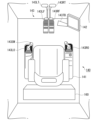
- FIG. 3 is a diagram showing the internal configuration of the operator's cab 140 according to the first embodiment.
- a driver's seat 141, an operation terminal 142, an operation device 143, and a control device 160 are provided in the driver's cab 140.
- the operation terminal 142 is provided near the driver's seat 141.
- the operation terminal 142 may be a display device constituted by, for example, a touch panel.
- the operation terminal 142 may also be equipped with a display device such as an LCD.
- the operating device 143 is a device for driving the traveling body 110, the rotating body 120, and the work machine 130 by manual operation by the operator.
- the operating device 143 includes a left operating lever 143LO, a right operating lever 143RO, a left foot pedal 143LF, a right foot pedal 143RF, a left travel lever 143LT, a right travel lever 143RT, and a swing brake pedal 143TB.
- the left operating lever 143LO is provided on the left side of the driver's seat 141.
- the right operating lever 143RO is provided on the right side of the driver's seat 141.
- the left operating lever 143LO is an operating mechanism for performing the rotating operation of the rotating body 120 and the excavation/dumping operation of the arm 132. Specifically, when the operator of the work machine 100 tilts the left operating lever 143LO forward, the arm 132 performs a dumping operation. When the operator of the work machine 100 tilts the left operating lever 143LO rearward, the arm 132 performs an excavation operation. When the operator of the work machine 100 tilts the left operating lever 143LO to the right, the rotating body 120 rotates to the right. When the operator of the work machine 100 tilts the left operating lever 143LO to the left, the rotating body 120 rotates to the left. In other embodiments, the rotating body 120 may rotate right or left when the left operating lever 143LO is tilted forward or backward, and the arm 132 may perform an excavation or dumping operation when the left operating lever 143LO is tilted left or right.
- the right operating lever 143RO is an operating mechanism for performing the digging/dumping operation of the bucket 133 and the raising/lowering operation of the boom 131. Specifically, when the operator of the work machine 100 tilts the right operating lever 143RO forward, the boom 131 is lowered. When the operator of the work machine 100 tilts the right operating lever 143RO backward, the boom 131 is raised. When the operator of the work machine 100 tilts the right operating lever 143RO to the right, the bucket 133 is dumped. When the operator of the work machine 100 tilts the right operating lever 143RO to the left, the bucket 133 is excavated. Note that in other embodiments, when the right operating lever 143RO is tilted forward/backward, the bucket 133 is dumped or excavated, and when the right operating lever 143RO is tilted left/right, the boom 131 is raised or lowered.
- the left foot pedal 143LF is located on the left side of the floor in front of the driver's seat 141.
- the right foot pedal 143RF is located on the right side of the floor in front of the driver's seat 141.
- the left travel lever 143LT is pivoted to the left foot pedal 143LF and configured so that the tilt of the left travel lever 143LT and the pressing down of the left foot pedal 143LF are linked.
- the right travel lever 143RT is pivoted to the right foot pedal 143RF and configured so that the tilt of the right travel lever 143RT and the pressing down of the right foot pedal 143RF are linked.
- the left foot pedal 143LF and the left travel lever 143LT correspond to the rotational drive of the left track of the running body 110. Specifically, when the operator of the work machine 100 pushes the left foot pedal 143LF or the left travel lever 143LT forward, the left track rotates in the forward direction. Conversely, when the operator of the work machine 100 pushes the left foot pedal 143LF or the left travel lever 143LT backward, the left track rotates in the reverse direction.
- the right foot pedal 143RF and right travel lever 143RT correspond to the rotational drive of the right track of the running body 110. Specifically, when the operator of the work machine 100 pushes the right foot pedal 143RF or the right travel lever 143RT forward, the right track rotates in the forward direction. Conversely, when the operator of the work machine 100 pushes the right foot pedal 143RF or the right travel lever 143RT backward, the right track rotates in the reverse direction.
- the control device 160 collects measurement data collected from multiple sensors equipped on the work machine 100 and the operation amount of the operation device 143, and stores the data in association with a timestamp. The control device 160 also transmits the time series of the measurement data and the operation amount to the work analysis device 300.
- the control device 160 is a computer equipped with a processor, main memory, storage, and interface (not shown).
- the storage of the control device 160 stores a data aggregation program.
- the processor of the control device 160 reads the data aggregation program from the storage and expands it into the main memory, and executes the collection process of the measurement data and the operation amount and the transmission process according to the data aggregation program.
- the control device 160 may be provided inside or outside the work machine 100.
- the work machine 100 is equipped with multiple sensors. Each sensor outputs a measurement value to the control device 160.
- the work machine 100 is equipped with at least a power meter that measures the power consumption of the battery 121, and a fuel gauge that measures the remaining charge of the battery 121.
- the work machine 100 may also be equipped with sensors such as a cylinder stroke sensor for identifying the attitude of the work implement 130, a pressure sensor for identifying the weight of the work implement 130, and an IMU that measures the rotation angle of the rotating body 120.
- FIG. 4 is a schematic block diagram showing the configuration of the work analysis device according to the first embodiment.
- the work analysis device 300 is a computer including a processor 31, a main memory 33, a storage 35, and an interface 37.
- the storage 35 stores a work analysis program.
- the processor 31 reads out the work analysis program from the storage 35, deploys it in the main memory 33, and executes processing in accordance with the work analysis program.
- the work analysis device 300 according to the first embodiment is provided outside the work machine 100, in other embodiments, some or all of the functions of the work analysis device 300 may be provided inside the work machine 100.
- Storage 35 examples include semiconductor memory, disk media, and tape media.
- Storage 35 may be internal media directly connected to the common communication line of the work analysis device 300, or may be external media connected to the work analysis device 300 via an interface 37.
- Storage 35 is a non-transitory tangible storage medium.
- the processor 31 is provided with a data acquisition unit 311, an input unit 312, an authentication unit 313, an estimation unit 314, a power calculation unit 315, a time calculation unit 316, an output unit 317, and a warning unit 318 by executing the work analysis program.
- the work analysis program stored in the storage 35 includes a prediction model 351.
- the prediction model is a trained model that is trained to input a time series of measurement data and operation amount and output a time series of work classifications.
- the prediction model 351 is trained by using a combination of a time series of measurement data and operation amount and a time series of labels of work classifications of the work machine 100 at the time the measurement data was collected as a learning data set.
- the prediction model may be, for example, a neural network model.
- the storage 35 has a storage area reserved for a status table 352 that stores status data for each work machine 100, and an account table 353 that stores user account data.
- the status table 352 stores the work machine ID, time, type of status data, and value of the status data in association with each other.
- the account table 353 stores the user ID, password, one or more work machine IDs for which viewing of status data is permitted, the period targeted for analysis, and the threshold value of remaining operating time in association with each other. The threshold value of remaining operating time is used to warn the user of the remaining capacity of the battery 121.
- the work analysis device 300 functions as a web server. That is, the work analysis device 300 accepts a request message (HTTP request) from a display device operated by a user, executes a predetermined process, and outputs a response message for screen display.
- HTTP request a request message
- the data acquisition unit 311 acquires a time series of status data indicating the status of the work machine 100 from the control device 160 of the work machine 100. In other words, the data acquisition unit 311 acquires multiple combinations of timestamps and status data.
- the status data may include measured values of each sensor of the work machine 100 and values calculated by the control device 160 based on the measured values.
- the data acquisition unit 311 associates the acquired time series of status data with the ID of the work machine 100 and stores it in the status table 352 of the storage 35.
- the input unit 312 accepts a request message from a user.
- the request message may include values of request parameters.
- the authentication unit 313 performs user authentication processing. For example, the authentication unit 313 performs authentication processing by checking the user ID and password indicated by the request parameters added to the request message against the data in the account table 353.
- the estimation unit 314 obtains a time series of task divisions based on the time series of new status data obtained by the data acquisition unit 311 and the prediction model 351 stored in the storage 35. For example, the estimation unit 314 obtains a time series of likelihoods related to task divisions in the following procedure. The estimation unit 314 obtains status data at the time when the task is specified from the time series of status data. Next, the estimation unit 314 obtains a time series of each task division based on the obtained status data.
- the estimation unit 314 identifies the classification of work into unit work and element work.
- a unit work is a task that accomplishes one work purpose.
- An element work is an element that constitutes a unit work, and is a series of actions or tasks that are classified according to purpose.
- Excavation is a task of digging up and scraping away soil or rocks with a bucket 133.
- Load rotation is a task of rotating the rotating body 120 while the bucket 133 is loaded with the scraped soil or rocks.
- Soil removal is the task of lowering the excavated soil or rocks from the bucket 133 onto a transport vehicle or to a designated location.
- Empty rotation is a task of rotating the rotating body 120 with no soil or rocks in the bucket 133.
- the waiting for soil discharge operation involves waiting for a transport vehicle to load the excavated soil or rocks into the bucket 133 .
- the loading platform pressing is a task of pressing down the soil loaded on the loading platform of a transport vehicle from above with a bucket 133 to level it.
- Compaction is the process of pushing soil and sand into disturbed ground with a bucket 133 to shape and strengthen the ground.
- Pushing and leveling is the task of sweeping and leveling the soil and sand with the bottom surface of the bucket 133.
- the broom work involves sweeping and leveling soil and sand with the side of the bucket 133.
- unit work divisions include "loading a dump truck,””collectingcargo,””driving,” and “parking.”
- Dump loading is the work of digging, scraping, and loading the scraped soil or rocks onto the bed of a transport vehicle such as a dump truck.
- Dump loading is a unit work consisting of excavation, turning the loaded load, unloading the soil, turning the empty load, waiting for the soil to be unloaded, and holding down the bed.
- Load collection is the task of collecting soil and sand produced by excavation etc. before loading it onto a transport vehicle.
- Load collection is a unit task that consists of excavation, loading rotation, soil removal, and empty loading rotation, and may include pushing and leveling. Traveling is a task of moving the work machine 100.
- Traveling as a unit task is a unit task made up of traveling as element tasks.
- the "stopped” state is a state in which there is no soil or rocks in the bucket 133 and the vehicle is stopped for a predetermined period of time or longer.
- the "stopped” state as a unit task is a unit task constituted by "stopped” element tasks.
- the power calculation unit 315 calculates the average power consumption and the power consumption per unit time for each unit task division based on the time series of the measurement data of the power sensor acquired by the data acquisition unit 311 and the time series of the unit task divisions estimated by the estimation unit 314. Specifically, the power calculation unit 315 divides the time series of the measurement data of the power sensor into each unit task division, and divides the sum of the power consumption represented by the measurement data for each division by the time related to the division, thereby obtaining the power consumption per unit time for each division. The power calculation unit 315 calculates the charging power per unit time based on the time series of the measurement data of the power sensor acquired by the data acquisition unit 311 and the time series of the division of the unit task estimated by the estimation unit 314. Specifically, the power calculation unit 315 can obtain the charging power per unit time by dividing the sum of the charging power represented by the measurement data when the battery 121 is being charged, among the measurement data of the power sensor, by the charging time.
- the time calculation unit 316 calculates the remaining operating time by dividing the remaining charge of the battery 121 acquired by the data acquisition unit 311 by the power consumption per unit time calculated by the power calculation unit 315.
- the time calculation unit 316 calculates the remaining charging time by dividing the difference between the maximum capacity of the battery 121 and the remaining charge of the battery 121 acquired by the data acquisition unit 311 by the charging power per unit time calculated by the power calculation unit 315.
- the output unit 317 outputs a response message for displaying a display screen showing the remaining operating time calculated by the time calculation unit 316 .
- a warning unit 318 displays warning information on the display screen when the remaining operating time calculated by the time calculation unit 316 falls below the designated time.
- the control device 160 of the work machine 100 transmits the sensor measurement data and time-series data of the operation amount of the operation device 143 at regular intervals to the work analysis device 300.
- the data acquisition unit 311 of the work analysis device 300 records the received time-series data in the storage 35 in association with the ID of the work machine 100.
- Users such as the operator of the work machine 100, the owner of the work machine, and the person in charge of the construction site access the work analysis device 300 using a display device such as a PC or smartphone to know the status of the work machine 100.
- a display device such as a PC or smartphone
- the user accesses the work analysis device 300 through a web browser on the display device.
- the display device may be the operation terminal 142 of the work machine 100.
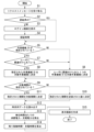
- Fig. 5 is a flowchart showing a screen presentation method by the work analysis device 300 according to the first embodiment. Note that the flowchart shown in Fig. 5 is merely an example, and the order or content of some of the processes may be different in other embodiments.
- the input unit 312 of the work analysis device 300 receives a request message from the display device (step S1)
- the authentication unit 313 determines whether or not the user has been authenticated (step S2). If authentication has not been performed (step S2: NO), the output unit 317 generates a response message for displaying a login screen for user authentication, and outputs it to the display device (step S3).
- the login screen includes an input form for a user ID and password. The user inputs the user ID and password on the login screen.
- the display device transmits a request message with the values of the user ID and password as request parameters.
- the authentication unit 313 performs authentication processing by comparing the user ID and password associated with the response parameters with the data in the account table 353 (step S4).
- step S2 If user authentication has been completed (step S2: YES), or if the authentication process has been completed in step S4, the work analysis device 300 starts generating a display screen for information regarding the remaining operating time of the work machine 100.
- the input unit 312 determines whether or not a value of a work machine ID that identifies the work machine 100 to be displayed is specified as a request parameter in the request message (step S5). If a value of the work machine ID is not specified as the request parameter (step S5: NO), the input unit 312 determines the work machine 100 associated with the first work machine ID among the one or more work machines 100 associated with the authenticated user in the account table 353 as the target work machine (step S6).
- step S7 the input unit 312 determines whether or not the work machine ID value is associated with the authenticated user in the account table 353 (step S7).
- step S7 the input unit 312 determines the work machine 100 related to the work machine ID as the target work machine (step S8). If the value of the work machine ID is not associated with the authenticated user in the account table 353, the input unit 312 determines the work machine 100 associated with the first work machine ID among the one or more work machines 100 associated with the authenticated user in the account table 353 as the target work machine (step S6).
- the input unit 312 determines whether or not the request message includes a value of a target period to be analyzed as a request parameter (step S9). If the value of the target period is not included as a request parameter (step S9: NO), the input unit 312 determines the target period to be the period associated with the authenticated user in the account table 353 (step S10). If the value of the target period is included as the request parameter (step S9: YES), the input unit 312 determines the target period to be the period specified by the request parameter (step S11). The input unit 312 rewrites the value of the target period associated with the authenticated user in the account table 353 to the value set in the request parameter.
- the estimation unit 314 reads out the determined work machine ID and the measurement data associated with the time within the target period ending at the current time and the operation amount of the operation device 143 as time series data from the state table 352 of the storage 35 (step S12).
- the estimation unit 314 inputs the read time series data into the prediction model 351 to generate a time series of the work categories of the work machine 100 within the target period.
- the power calculation unit 315 calculates the power consumption and charging power per unit time based on the time series of the task categories and the measurement data of the power sensor (step S13). Specifically, the power consumption per unit time is calculated by dividing the sum of the measurement data of the power sensor in the target period acquired by the data acquisition unit 311 by the length of the target period. The power calculation unit 315 also divides the measurement data of the power sensor into task categories based on the time series of the task categories. The power calculation unit 315 calculates the power consumption per unit time for each task category by dividing the sum of the measurement data of the power sensor by the length of time related to that category. The power calculation unit 315 also calculates the charging power per unit time by dividing the sum of the charging power represented by the measurement data when the battery 121 is being charged, among the measurement data of the power sensor, by the charging time.
- the time calculation unit 316 calculates the remaining operating time and the remaining charging time based on the power consumption and charging power per unit time calculated in step S13 (step S14). Specifically, the time calculation unit 316 calculates the remaining operating time when the work of the target period is repeated and the operating time when only the work of each category is repeated by dividing the remaining charge of the battery 121 acquired by the data acquisition unit 311 by the power consumption per unit time calculated by the power calculation unit 315. The time calculation unit 316 calculates the remaining charging time by dividing the difference between the maximum capacity of the battery 121 and the remaining charge of the battery 121 acquired by the data acquisition unit 311 by the charging power per unit time calculated by the power calculation unit 315.
- the output unit 317 generates a display screen that displays the current remaining charge of the battery 121, the progress of the remaining charge up to the present, the remaining operating time, and the charging time, and transmits a response message to display the display screen (step S15).
- the display screen includes a work machine selection form G1, a battery remaining amount graph G2, a remaining operating time graph G3, a charging time graph G4, and a battery remaining amount transition graph G5.
- the work machine selection form G1 accepts the selection of the work machine 100 associated with the authenticated user.
- the initial value of the work machine selection form G1 indicates the target work machine determined in step S6 or step S8.
- the battery remaining capacity graph G2 displays the remaining capacity of the battery 121 in percentage.
- the remaining operation time graph G3 shows the remaining operation time in the case of standard use, the remaining operation time in the case of the most recent N hours of use, the remaining operation time in the case of only traveling, the remaining operation time in the case of only loading a dump truck, and the remaining operation time in the case of only other work, using bar graphs and numerical values (the end timing of the operable period).
- the remaining operation time in the case of standard use is the remaining operation time calculated based on the standard power consumption assumed at the time of designing the work machine 100, not on the data received from the work machine 100.
- the end timing of the operable period is obtained by adding the remaining operation time to the current time.
- the "N hours" in the label of the remaining operation time in the case of the most recent N hours of use is a list box, and any period can be selected. Note that the display screen may display either the remaining operation time or the end timing of the operable period.
- the charging time graph G4, like the remaining operating time graph G3, represents the length of the charging time using a bar graph and numerical values.
- the battery remaining capacity transition graph G5 is a bar graph showing the transition of the remaining capacity of the battery 121 over one day.
- the user can perform operations taking into consideration the remaining operating time of the work machine 100.
- a user can use the display device to change the values in the work machine selection form G1 shown in Fig. 6 to display the status of the battery 121 of another work machine 100.
- the display device returns the process to step S1 and transmits a request message in which the changed value of the work machine ID is specified as a request parameter.
- a user can change the value of the target period of the remaining operating time graph G3 shown in Fig. 6 using the display device to change the period for which other power consumption is calculated.
- the display device When the user changes the value of the target period of the remaining operating time graph G3, the display device returns to step S1 and transmits a request message in which the changed value of the target period is specified as a request parameter.
- the input unit 312 accepts input of the value of the target period through the request message.
- the input unit 312 is an example of a period input unit.
- the user can operate the display device to send a request message to the work analysis device 300 requesting a change to the threshold used to determine the warning in step S16.
- the request message specifies the changed threshold as a request parameter.
- the input unit 312 of the work analysis device 300 receives a request message in which a threshold is specified in the request parameter, it rewrites the threshold associated with the user ID of the sender of the request message in the account table 353.
- the input unit 312 is an example of a threshold input unit.
- the warning unit 318 of the work analysis device 300 determines at regular intervals whether the remaining operating time when using the work machine 100 in the usage mode related to the target period recorded in the account table 353 falls below the threshold recorded in the account table 353. If the remaining operating time falls below the threshold, the warning unit 318 issues a warning about the remaining operating time to the user associated with the threshold. For example, the warning unit 318 may send a warning e-mail to the user's e-mail address, or may send a push notification to a display device associated with the user.
- the work analysis device 300 includes a time calculation unit 316 and an output unit 317.
- the time calculation unit 316 calculates the remaining operation time of the work machine 100 based on the remaining charge of the battery 121 and the behavior of the work machine 100 within a predetermined period of time.
- the output unit 317 outputs a signal for displaying the remaining operation time. This allows the work analysis device 300 to present the remaining operation time according to the behavior of the work machine 100. Therefore, the work analysis device 300 can present a highly reliable remaining operation time.
- the work analysis device 300 further includes an estimation unit 314.
- the estimation unit 314 estimates the progress of the work content of the work machine 100 over a predetermined period of time based on the measurement signals of the work machine 100.
- the time calculation unit 316 calculates the remaining operating time if the predetermined work content (driving, dump truck loading, etc.) is continued based on the power consumption related to the predetermined work content. This allows the user to consider the content of work that can be performed before charging and the work time. In particular, by the time calculation unit 316 calculating the remaining operating time related to the driving of the work machine 100, the user can consider whether or not to continue the work based on the time required for driving to a charging station to charge the battery 121.
- the work analysis device 300 may be configured by a single computer, or the configuration of the work analysis device 300 may be divided and arranged on multiple computers, and the multiple computers may function as the work analysis device 300 by working together.
- some of the computers that configure the work analysis device 300 may be mounted inside the work machine 100 (for example, realized by the control device 160), and other computers may be provided outside the work machine.
- the work analysis device 300 has been described as an example in which the charging time required for the battery 121 to be fully charged is displayed on the display screen, but the charging time required for the battery 121 to reach a battery charge amount specified by the user may also be displayed.
- the battery charge amount specified by the user is, for example, a value between 70% and 90% of the remaining battery charge compared to full charge.
- the time calculation unit 316 calculates the remaining charging time by dividing the difference between the battery charge amount specified by the user and the remaining amount of the battery 121 acquired by the data acquisition unit 311 by the charging power per unit time calculated by the power calculation unit 315.
- the work analysis device 300 may also display on the display screen, together with the charging time graph G4, the remaining operating time when the battery is fully charged and the timing at which the operable period will end.
- the work analysis device 300 may also display the remaining operating time and the timing at which the operable period will end when the charge level of the battery 121 reaches the battery charge level specified by the user.
- the work analysis device 300 is a web server, and a display screen is displayed when a display device accesses the work analysis device 300.
- the work analysis device 300 may be implemented in the control device 160 or the operation terminal 142 of the work machine 100, and the work analysis device 300 may perform analysis and display control offline.
Landscapes
- Engineering & Computer Science (AREA)
- Power Engineering (AREA)
- Mechanical Engineering (AREA)
- Transportation (AREA)
- General Engineering & Computer Science (AREA)
- Structural Engineering (AREA)
- Civil Engineering (AREA)
- Mining & Mineral Resources (AREA)
- Life Sciences & Earth Sciences (AREA)
- Sustainable Development (AREA)
- Sustainable Energy (AREA)
- Component Parts Of Construction Machinery (AREA)
- Charge And Discharge Circuits For Batteries Or The Like (AREA)
- Electric Propulsion And Braking For Vehicles (AREA)
Abstract
算出部(315)は、バッテリ(121)の残量と所定期間内の作業機械(100)の挙動とに基づいて、作業機械の残り稼働時間に関する情報を算出する。出力部(317)は、残り稼働時間に関する情報を表示するための信号を出力する。
Description
本開示は、作業機械の表示制御システムに関する。
本願は、2023年6月29日に日本に出願された特願2023-106844号に基づき優先権を主張し、その内容をここに援用する。
本願は、2023年6月29日に日本に出願された特願2023-106844号に基づき優先権を主張し、その内容をここに援用する。
市街地等における建設作業においては、ゼロエミッション、かつ、騒音が少ない電気駆動の作業機械が利用されることがある。電気駆動の作業機械は、エンジンや燃料タンクを備えない代わりに、油圧ポンプ等を駆動させる電動モータ、及び、当該電動モータに電力を供給するバッテリ等の蓄電装置を備える。このような電気駆動の作業機械は、エンジン駆動の作業機械と比較して、充電に時間を要する。そのため、オペレータにとって、電気駆動の作業機械の残り稼働時間を認識することは重要である。
特許文献1には、電気モータを動力源とする作業機械に搭載され、作業車両のバッテリ残量や残り稼働時間を表示する表示装置が開示されている。
特許文献1には、電気モータを動力源とする作業機械に搭載され、作業車両のバッテリ残量や残り稼働時間を表示する表示装置が開示されている。
ところで、作業機械の消費電力は、作業機械の挙動によって異なる。そのため、バッテリの残量と、予め定められた単位時間当たりの消費電力とから計算された残り稼働時間は、実際の残り稼働時間と乖離する場合がある。
本開示の目的は、残り稼働時間に関する情報を適切に提示することができる作業機械の表示制御システムを提供することにある。
本開示の目的は、残り稼働時間に関する情報を適切に提示することができる作業機械の表示制御システムを提供することにある。
本開示の一態様によれば、作業機械の表示制御システムは、バッテリで駆動する作業機械の表示制御システムであって、前記バッテリの残量と所定期間内の前記作業機械の挙動とに基づいて、前記作業機械の残り稼働時間に関する情報を算出する算出部と、前記残り稼働時間に関する情報を表示するための信号を出力する出力部と、を備える。
上記態様によれば、表示制御システムは残り稼働時間に関する情報を適切に提示することができる。
〈第1の実施形態〉
《全体構成》
図1は、第1の実施形態に係る表示制御システム1の構成を示す概略図である。表示制御システム1は、作業機械100と作業分析装置300とを備える。作業分析装置300は、作業機械100の作業を分析し、作業機械の作業履歴および残り稼働時間に関する情報を表示する画面を生成する。第1の実施形態において、残り稼働時間に関する情報は、残り稼働時間と稼働可能な期間の終了タイミングを含む。ユーザは、作業分析装置300が出力する画面を視認することで、作業機械100の残り稼働時間を認識することができる。
《全体構成》
図1は、第1の実施形態に係る表示制御システム1の構成を示す概略図である。表示制御システム1は、作業機械100と作業分析装置300とを備える。作業分析装置300は、作業機械100の作業を分析し、作業機械の作業履歴および残り稼働時間に関する情報を表示する画面を生成する。第1の実施形態において、残り稼働時間に関する情報は、残り稼働時間と稼働可能な期間の終了タイミングを含む。ユーザは、作業分析装置300が出力する画面を視認することで、作業機械100の残り稼働時間を認識することができる。
作業機械100は、作業分析装置300による作業分析の対象である。作業機械100の例としては、油圧ショベルやホイルローダなどの他の作業機械が挙げられる。なお、第1の実施形態においては、作業機械100の例として電気駆動の油圧ショベルを挙げて説明する。作業機械100には、複数のセンサが設けられ、各センサの計測値に係る情報が作業分析装置300に送信される。
《作業機械100》
図2は、第1の実施形態に係る作業機械100の構成を示す図である。作業機械100は、施工現場にて稼働し、土砂などの施工対象を掘削し、ダンプトラックなどの積込対象Tのベッセルなど荷台に積み込む。作業機械100の例としては、フェイスショベル、バックホウショベル、ロープショベルなどが挙げられる。また作業機械100は電動駆動するものであってもよいし、油圧駆動するものであってもよい。第1の実施形態に係る作業機械100は、バックホウショベルである。作業機械100は、走行体110、旋回体120、作業機130及び運転室140を備える。積込対象Tの例としては、ダンプトラック、ホッパなどが挙げられる。
図2は、第1の実施形態に係る作業機械100の構成を示す図である。作業機械100は、施工現場にて稼働し、土砂などの施工対象を掘削し、ダンプトラックなどの積込対象Tのベッセルなど荷台に積み込む。作業機械100の例としては、フェイスショベル、バックホウショベル、ロープショベルなどが挙げられる。また作業機械100は電動駆動するものであってもよいし、油圧駆動するものであってもよい。第1の実施形態に係る作業機械100は、バックホウショベルである。作業機械100は、走行体110、旋回体120、作業機130及び運転室140を備える。積込対象Tの例としては、ダンプトラック、ホッパなどが挙げられる。
走行体110は、作業機械100を走行可能に支持する。走行体110は、左右に設けられた2つの無限軌道111と、各無限軌道111を駆動するための2つの走行モータ112を備える。走行体110は、支持部の一例である。
旋回体120は、走行体110に旋回中心回りに旋回可能に支持される。
作業機130は、油圧により駆動する。作業機130は、旋回体120の前部に上下方向に駆動可能に支持される。
運転室140は、オペレータが搭乗し、作業機械100の操作を行うためのスペースである。運転室140は、旋回体120の左前部に設けられる。
ここで、旋回体120のうち作業機130が取り付けられる部分を前部という。また、旋回体120について、前部を基準に、反対側の部分を後部、左側の部分を左部、右側の部分を右部という。
旋回体120は、走行体110に旋回中心回りに旋回可能に支持される。
作業機130は、油圧により駆動する。作業機130は、旋回体120の前部に上下方向に駆動可能に支持される。
運転室140は、オペレータが搭乗し、作業機械100の操作を行うためのスペースである。運転室140は、旋回体120の左前部に設けられる。
ここで、旋回体120のうち作業機130が取り付けられる部分を前部という。また、旋回体120について、前部を基準に、反対側の部分を後部、左側の部分を左部、右側の部分を右部という。
《旋回体120の構成》
旋回体120は、バッテリ121、油圧ポンプ122、コントロールバルブ123、旋回モータ124を備える。
バッテリ121は、油圧ポンプ122を駆動する動力源である。
油圧ポンプ122は、バッテリ121から供給される電力により駆動される電動ポンプである。油圧ポンプ122は、コントロールバルブ123を介して各アクチュエータ(ブームシリンダ131C、アームシリンダ132C、バケットシリンダ133C、走行モータ112、及び旋回モータ124)に作動油を供給する。
コントロールバルブ123は、油圧ポンプ122から供給される作動油の流量を制御する。
旋回モータ124は、コントロールバルブ123を介して油圧ポンプ122から供給される作動油によって駆動し、旋回体120を旋回させる。
旋回体120は、バッテリ121、油圧ポンプ122、コントロールバルブ123、旋回モータ124を備える。
バッテリ121は、油圧ポンプ122を駆動する動力源である。
油圧ポンプ122は、バッテリ121から供給される電力により駆動される電動ポンプである。油圧ポンプ122は、コントロールバルブ123を介して各アクチュエータ(ブームシリンダ131C、アームシリンダ132C、バケットシリンダ133C、走行モータ112、及び旋回モータ124)に作動油を供給する。
コントロールバルブ123は、油圧ポンプ122から供給される作動油の流量を制御する。
旋回モータ124は、コントロールバルブ123を介して油圧ポンプ122から供給される作動油によって駆動し、旋回体120を旋回させる。
《作業機130の構成》
作業機130は、ブーム131、アーム132、作業具としてのバケット133、ブームシリンダ131C、アームシリンダ132C、及びバケットシリンダ133Cを備える。作業具の他の例として、クラムバケット、チルトバケット、チルトローテートバケット、グラップル、リフティングマグネットなどの先端アタッチメントが挙げられる。
作業機130は、ブーム131、アーム132、作業具としてのバケット133、ブームシリンダ131C、アームシリンダ132C、及びバケットシリンダ133Cを備える。作業具の他の例として、クラムバケット、チルトバケット、チルトローテートバケット、グラップル、リフティングマグネットなどの先端アタッチメントが挙げられる。
ブーム131の基端部は、旋回体120にブームピンを介して回転可能に取り付けられる。なお、図1に示す作業機械100においては、ブーム131が旋回体120の正面中央部分に設けられるが、これに限られず、ブーム131は左右方向にオフセットして取り付けられたものであってもよい。この場合、旋回体120の旋回中心は作業機130の動作平面上に位置しない。
アーム132は、ブーム131とバケット133とを連結する。アーム132の基端部は、ブーム131の先端部にアームピンを介して回転可能に取り付けられる。
バケット133は、アーム132の先端部にピンを介して回転可能に取り付けられる。バケット133を支持する部材として、ブーム131、アーム132がある。バケット133は、掘削した土砂を収容するための容器として機能する。
アーム132は、ブーム131とバケット133とを連結する。アーム132の基端部は、ブーム131の先端部にアームピンを介して回転可能に取り付けられる。
バケット133は、アーム132の先端部にピンを介して回転可能に取り付けられる。バケット133を支持する部材として、ブーム131、アーム132がある。バケット133は、掘削した土砂を収容するための容器として機能する。
ブームシリンダ131Cは、ブーム131を作動させるための油圧シリンダである。ブームシリンダ131Cの基端部は、旋回体120に取り付けられる。ブームシリンダ131Cの先端部は、ブーム131に取り付けられる。
アームシリンダ132Cは、アーム132を駆動するための油圧シリンダである。アームシリンダ132Cの基端部は、ブーム131に取り付けられる。アームシリンダ132Cの先端部は、アーム132に取り付けられる。
バケットシリンダ133Cは、バケット133を駆動するための油圧シリンダである。バケットシリンダ133Cの基端部は、アーム132に取り付けられる。バケットシリンダ133Cの先端部は、バケット133を回動させるリンク機構に取り付けられる。
アームシリンダ132Cは、アーム132を駆動するための油圧シリンダである。アームシリンダ132Cの基端部は、ブーム131に取り付けられる。アームシリンダ132Cの先端部は、アーム132に取り付けられる。
バケットシリンダ133Cは、バケット133を駆動するための油圧シリンダである。バケットシリンダ133Cの基端部は、アーム132に取り付けられる。バケットシリンダ133Cの先端部は、バケット133を回動させるリンク機構に取り付けられる。
《運転室140の構成》
図3は、第1の実施形態に係る運転室140の内部の構成を示す図である。
運転室140内には、運転席141、操作端末142、操作装置143および制御装置160が設けられる。操作端末142は、運転席141の近傍に設けられる。操作端末142は、例えばタッチパネルで構成された表示装置であってよい。また、操作端末142は、LCDなどの表示装置を備えるものであってよい。
図3は、第1の実施形態に係る運転室140の内部の構成を示す図である。
運転室140内には、運転席141、操作端末142、操作装置143および制御装置160が設けられる。操作端末142は、運転席141の近傍に設けられる。操作端末142は、例えばタッチパネルで構成された表示装置であってよい。また、操作端末142は、LCDなどの表示装置を備えるものであってよい。
操作装置143は、オペレータの手動操作によって走行体110、旋回体120及び作業機130を駆動させるための装置である。操作装置143は、左操作レバー143LO、右操作レバー143RO、左フットペダル143LF、右フットペダル143RF、左走行レバー143LT、右走行レバー143RT、旋回ブレーキペダル143TBを備える。
左操作レバー143LOは、運転席141の左側に設けられる。右操作レバー143ROは、運転席141の右側に設けられる。
左操作レバー143LOは、旋回体120の旋回動作、及び、アーム132の掘削/ダンプ動作を行うための操作機構である。具体的には、作業機械100のオペレータが左操作レバー143LOを前方に倒すと、アーム132がダンプ動作する。また、作業機械100のオペレータが左操作レバー143LOを後方に倒すと、アーム132が掘削動作する。また、作業機械100のオペレータが左操作レバー143LOを右方向に倒すと、旋回体120が右旋回する。また、作業機械100のオペレータが左操作レバー143LOを左方向に倒すと、旋回体120が左旋回する。なお、他の実施形態においては、左操作レバー143LOを前後方向に倒した場合に旋回体120が右旋回又は左旋回し、左操作レバー143LOが左右方向に倒した場合にアーム132が掘削動作又はダンプ動作してもよい。
右操作レバー143ROは、バケット133の掘削/ダンプ動作、及び、ブーム131の上げ/下げ動作を行うための操作機構である。具体的には、作業機械100のオペレータが右操作レバー143ROを前方に倒すと、ブーム131の下げ動作が実行される。また、作業機械100のオペレータが右操作レバー143ROを後方に倒すと、ブーム131の上げ動作が実行される。また、作業機械100のオペレータが右操作レバー143ROを右方向に倒すと、バケット133のダンプ動作が行われる。また、作業機械100のオペレータが右操作レバー143ROを左方向に倒すと、バケット133の掘削動作が行われる。なお、他の実施形態においては、右操作レバー143ROを前後方向に倒した場合に、バケット133がダンプ動作又は掘削動作し、右操作レバー143ROを左右方向に倒した場合にブーム131が上げ動作又は下げ動作してもよい。
左フットペダル143LFは、運転席141の前方の床面の左側に配置される。右フットペダル143RFは、運転席141の前方の床面の右側に配置される。左走行レバー143LTは、左フットペダル143LFに軸支され、左走行レバー143LTの傾斜と左フットペダル143LFの押し下げが連動するように構成される。右走行レバー143RTは、右フットペダル143RFに軸支され、右走行レバー143RTの傾斜と右フットペダル143RFの押し下げが連動するように構成される。
左フットペダル143LF及び左走行レバー143LTは、走行体110の左側履帯の回転駆動に対応する。具体的には、作業機械100のオペレータが左フットペダル143LF又は左走行レバー143LTを前方に倒すと、左側履帯は前進方向に回転する。また、作業機械100のオペレータが左フットペダル143LF又は左走行レバー143LTを後方に倒すと、左側履帯は後進方向に回転する。
右フットペダル143RF及び右走行レバー143RTは、走行体110の右側履帯の回転駆動に対応する。具体的には、作業機械100のオペレータが右フットペダル143RF又は右走行レバー143RTを前方に倒すと、右側履帯は前進方向に回転する。また、作業機械100のオペレータが右フットペダル143RF又は右走行レバー143RTを後方に倒すと、右側履帯は後進方向に回転する。
制御装置160は、作業機械100が備える複数のセンサから収集した計測データと、操作装置143の操作量とを収集し、タイムスタンプに関連付けて記憶する。また制御装置160は、計測データおよび操作量の時系列を作業分析装置300に送信する。制御装置160は、図示しないプロセッサ、メインメモリ、ストレージ、インタフェースを備えるコンピュータである。制御装置160のストレージは、データ集約プログラムを記憶する。制御装置160のプロセッサは、データ集約プログラムをストレージから読み出してメインメモリに展開し、データ集約プログラムに従った計測データおよび操作量の収集処理、ならびに送信処理を実行する。なお、制御装置160は、作業機械100の内部に設けられてもよいし外部に設けられてもよい。
作業機械100は、複数のセンサを備える。各センサは、計測値を制御装置160に出力する。作業機械100は、少なくともバッテリ121の消費電力を計測する電力計と、バッテリ121の残量を計測する残量計とを備える。作業機械100は、センサとして、作業機130の姿勢を特定するためのシリンダのストロークセンサ、作業機130の重量を特定するための圧力センサ、旋回体120の旋回角度を計測するIMUなどを備えていてもよい。
《作業分析装置の構成》
図4は、第1の実施形態に係る作業分析装置の構成を示す概略ブロック図である。
作業分析装置300は、プロセッサ31、メインメモリ33、ストレージ35、インタフェース37を備えるコンピュータである。ストレージ35は、作業分析プログラムを記憶する。プロセッサ31は、作業分析プログラムをストレージ35から読み出してメインメモリ33に展開し、作業分析プログラムに従った処理を実行する。なお、第1の実施形態に係る作業分析装置300は、作業機械100の外部に設けられるが、他の実施形態においては、作業分析装置300の機能の一部または全部が作業機械100の内部に設けられてもよい。
図4は、第1の実施形態に係る作業分析装置の構成を示す概略ブロック図である。
作業分析装置300は、プロセッサ31、メインメモリ33、ストレージ35、インタフェース37を備えるコンピュータである。ストレージ35は、作業分析プログラムを記憶する。プロセッサ31は、作業分析プログラムをストレージ35から読み出してメインメモリ33に展開し、作業分析プログラムに従った処理を実行する。なお、第1の実施形態に係る作業分析装置300は、作業機械100の外部に設けられるが、他の実施形態においては、作業分析装置300の機能の一部または全部が作業機械100の内部に設けられてもよい。
ストレージ35の例としては、半導体メモリ、ディスクメディアおよびテープメディア等が挙げられる。ストレージ35は、作業分析装置300の共通通信線に直接接続された内部メディアであってもよいし、インタフェース37を介して作業分析装置300に接続される外部メディアであってもよい。ストレージ35は、一時的でない有形の記憶媒体である。
プロセッサ31は、作業分析プログラムの実行により、データ取得部311、入力部312、認証部313、推定部314、電力算出部315、時間算出部316、出力部317、警告部318を備える。ストレージ35に記憶される作業分析プログラムには、予測モデル351が含まれる。予測モデルは、計測データおよび操作量の時系列を入力して、作業の区分の時系列を出力するように学習された学習済みモデルである。予測モデル351は、計測データおよび操作量の時系列と、当該計測データが収集されたときの作業機械100の作業の区分のラベルの時系列との組み合わせを学習用データセットとして学習される。予測モデルは、例えばニューラルネットワークモデルであってよい。またストレージ35には、作業機械100ごとの状態データを格納する状態テーブル352と、ユーザのアカウントデータを格納するアカウントテーブル353の記憶領域が確保される。
状態テーブル352は、作業機械IDと、時刻と、状態データの種類と、状態データの値とを関連づけて格納する。アカウントテーブル353は、ユーザIDと、パスワードと、状態データの閲覧が許可される1以上の作業機械IDと、分析の対象期間と、残り稼働時間の閾値とを関連付けて記憶する。残り稼働時間の閾値は、ユーザに対するバッテリ121残量の警告のために用いられる。
第1の実施形態に係る作業分析装置300はウェブサーバとして機能する。すなわち、作業分析装置300は、ユーザが操作する表示装置からリクエストメッセージ(HTTPリクエスト)を受け付け、所定の処理を実行して画面表示のためのレスポンスメッセージを出力する。
データ取得部311は、作業機械100の制御装置160から作業機械100の状態を示す状態データの時系列を取得する。つまり、データ取得部311は、タイムスタンプと状態データの複数の組み合わせを取得する。状態データは、作業機械100の各センサの計測値および計測値に基づいて制御装置160が求めた値を含んでよい。データ取得部311は、取得した状態データの時系列を、作業機械100のIDに関連付けてストレージ35の状態テーブル352に記憶させる。
入力部312は、ユーザからリクエストメッセージを受け付ける。リクエストメッセージには、リクエストパラメータの値が含まれ得る。
認証部313は、ユーザの認証処理を行う。例えば、認証部313は、リクエストメッセージに付加されたリクエストパラメータが示すユーザIDおよびパスワードを、アカウントテーブル353のデータと照合することで、認証処理を行う。
推定部314は、データ取得部311が取得した新たな状態データの時系列と、ストレージ35が記憶する予測モデル351とに基づいて作業の区分の時系列を得る。例えば、推定部314は、以下の手順で作業の区分に係る尤度の時系列を得る。推定部314は、状態データの時系列から、作業を特定する時点の状態データを取得する。次に推定部314は、取得した状態データに基づいて各作業の区分の時系列を取得する。
推定部314は、作業の区分として、単位作業の区分と要素作業の区分とを特定する。 単位作業とは、一の作業目的を遂行する作業である。要素作業とは、単位作業を構成する要素であって目的別に区分される一連の動作または作業を示す作業である。
要素作業の区分の例としては、「掘削」、「積荷旋回」、「排土」、「空荷旋回」、「排土待ち」、「荷台抑え」、「転圧」、「押し均し」、「ホウキ」などが挙げられる。 掘削は、バケット133によって土砂または岩石を掘り、削り取る作業である。
積荷旋回は、削り取った土砂または岩石をバケット133に抱えたまま、旋回体120を旋回させる作業である。
排土は、削り取った土砂または岩石を、バケット133から運搬車両または所定の場所に下ろす作業である。
空荷旋回は、バケット133に土砂および岩石が無い状態で、旋回体120を旋回させる作業である。
排土待ちは、削り取った土砂または岩石をバケット133に抱えたまま、積み込むための運搬車両を待機している作業である。
荷台押えは、運搬車両の荷台に積み込んだ土砂を上からバケット133で押えて平らにする作業である。
転圧は、乱れた地盤に対してバケット133で土砂を押し込み、地盤を成形し、また強化する作業である。
押し均しは、バケット133の底面で土砂を払い均す作業である。
ホウキは、バケット133の側面で土砂を払い均す作業である。
積荷旋回は、削り取った土砂または岩石をバケット133に抱えたまま、旋回体120を旋回させる作業である。
排土は、削り取った土砂または岩石を、バケット133から運搬車両または所定の場所に下ろす作業である。
空荷旋回は、バケット133に土砂および岩石が無い状態で、旋回体120を旋回させる作業である。
排土待ちは、削り取った土砂または岩石をバケット133に抱えたまま、積み込むための運搬車両を待機している作業である。
荷台押えは、運搬車両の荷台に積み込んだ土砂を上からバケット133で押えて平らにする作業である。
転圧は、乱れた地盤に対してバケット133で土砂を押し込み、地盤を成形し、また強化する作業である。
押し均しは、バケット133の底面で土砂を払い均す作業である。
ホウキは、バケット133の側面で土砂を払い均す作業である。
単位作業の区分の例としては、「ダンプ積込」、「積荷集め」、「走行」、「停車」などが挙げられる。
ダンプ積込は、土砂または岩石を掘り、削り取り、削り取った土砂または岩石をダンプトラックなどの運搬車両の荷台に積み込む作業である。ダンプ積込は、掘削、積荷旋回、排土、空荷旋回、排土待ちおよび荷台押えで構成される単位作業である。
積荷集めは、掘削等によって出た土砂を、運搬車両に積む前に集めておく作業である。積荷集めは、掘削、積荷旋回、排土、空荷旋回で構成され、押し均しを含み得る単位作業である。
走行は、作業機械100を移動させる作業である。単位作業としての走行は、要素作業としての走行から構成される単位作業である。
停車は、バケット133に土砂および岩石が無く、かつ所定時間以上停止している状態である。単位作業としての停車は、要素作業としての停車から構成される単位作業である。
ダンプ積込は、土砂または岩石を掘り、削り取り、削り取った土砂または岩石をダンプトラックなどの運搬車両の荷台に積み込む作業である。ダンプ積込は、掘削、積荷旋回、排土、空荷旋回、排土待ちおよび荷台押えで構成される単位作業である。
積荷集めは、掘削等によって出た土砂を、運搬車両に積む前に集めておく作業である。積荷集めは、掘削、積荷旋回、排土、空荷旋回で構成され、押し均しを含み得る単位作業である。
走行は、作業機械100を移動させる作業である。単位作業としての走行は、要素作業としての走行から構成される単位作業である。
停車は、バケット133に土砂および岩石が無く、かつ所定時間以上停止している状態である。単位作業としての停車は、要素作業としての停車から構成される単位作業である。
電力算出部315は、データ取得部311が取得した電力センサの計測データの時系列と、推定部314が推定した単位作業の区分の時系列とに基づいて平均消費電力および単位作業の区分ごとの単位時間当たりの消費電力を算出する。具体的には、電力算出部315は、電力センサの計測データの時系列を単位作業の区分ごとに切り分け、区分ごとに、計測データが表す消費電力の総和を、当該区分に係る時間で除算することで、区分ごとの単位時間当たりの消費電力を得ることができる。
電力算出部315は、データ取得部311が取得した電力センサの計測データの時系列と、推定部314が推定した単位作業の区分の時系列とに基づいて単位時間当たりの充電電力を算出する。具体的には、電力算出部315は、電力センサの計測データのうち、バッテリ121の充電がなされているときの計測データが表す充電電力の総和を、充電時間で除算することで、単位時間当たりの充電電力を得ることができる。
電力算出部315は、データ取得部311が取得した電力センサの計測データの時系列と、推定部314が推定した単位作業の区分の時系列とに基づいて単位時間当たりの充電電力を算出する。具体的には、電力算出部315は、電力センサの計測データのうち、バッテリ121の充電がなされているときの計測データが表す充電電力の総和を、充電時間で除算することで、単位時間当たりの充電電力を得ることができる。
時間算出部316は、データ取得部311が取得したバッテリ121の残量を電力算出部315が算出した単位時間当たりの消費電力で除算することで、残り稼働時間を算出する。時間算出部316は、バッテリ121の最大容量とデータ取得部311が取得したバッテリ121の残量との差を、電力算出部315が算出した単位時間当たりの充電電力で除算することで、残り充電時間を算出する。
出力部317は、時間算出部316が算出した残り稼働時間の表示画面を表示させるためのレスポンスメッセージを出力する。
警告部318は時間算出部316が算出した残り稼働時間が指定時間を下回る場合に、表示画面に警告情報を付す。
警告部318は時間算出部316が算出した残り稼働時間が指定時間を下回る場合に、表示画面に警告情報を付す。
《表示制御システム1の動作》
作業機械100の制御装置160は、一定時間ごとにセンサの計測データおよび操作装置143の操作量の時系列データを作業分析装置300に送信する。作業分析装置300のデータ取得部311は、受信した時系列データを作業機械100のIDに関連付けてストレージ35に記録する。
作業機械100の制御装置160は、一定時間ごとにセンサの計測データおよび操作装置143の操作量の時系列データを作業分析装置300に送信する。作業分析装置300のデータ取得部311は、受信した時系列データを作業機械100のIDに関連付けてストレージ35に記録する。
作業機械100のオペレータ、作業機械のオーナー、施工現場の責任者などのユーザは、作業機械100の状態を知るために、PCやスマートフォンなどの表示装置を用いて作業分析装置300にアクセスする。例えば、ユーザは表示装置のウェブブラウザによって作業分析装置300にアクセスする。表示装置は、作業機械100の操作端末142であってもよい。
図5は、第1の実施形態に係る作業分析装置300による画面の提示方法を示すフローチャートである。なお、図5に示すフローチャートはあくまで一例であり、他の実施形態においては一部の処理の順や内容が異なっていてもよい。
作業分析装置300の入力部312が表示装置からリクエストメッセージを受け付けると(ステップS1)、認証部313はユーザの認証がなされているか否かを判定する(ステップS2)。認証がなされていない場合(ステップS2:NO)、出力部317はユーザの認証のためのログイン画面を表示させるためのレスポンスメッセージを生成し、表示装置に出力する(ステップS3)。ログイン画面には、ユーザIDとパスワードの入力フォームが含まれる。ユーザは、ログイン画面においてユーザIDとパスワードを入力する。これにより表示装置はユーザIDとパスワードの値をリクエストパラメータとするリクエストメッセージを送信する。
作業分析装置300の入力部312が表示装置からリクエストメッセージを受け付けると(ステップS1)、認証部313はユーザの認証がなされているか否かを判定する(ステップS2)。認証がなされていない場合(ステップS2:NO)、出力部317はユーザの認証のためのログイン画面を表示させるためのレスポンスメッセージを生成し、表示装置に出力する(ステップS3)。ログイン画面には、ユーザIDとパスワードの入力フォームが含まれる。ユーザは、ログイン画面においてユーザIDとパスワードを入力する。これにより表示装置はユーザIDとパスワードの値をリクエストパラメータとするリクエストメッセージを送信する。
入力部312がリクエストメッセージを受け付けると、認証部313はレスポンスパラメータに係るユーザIDおよびパスワードを、アカウントテーブル353のデータと照合することで、認証処理を行う(ステップS4)。
ユーザの認証が完了している場合(ステップS2:YES)、またはステップS4で認証処理を完了した場合、作業分析装置300は作業機械100の残り稼働時間に関する情報の表示画面の生成を開始する。
入力部312は、リクエストメッセージに、リクエストパラメータとして表示対象の作業機械100を特定する作業機械IDの値が指定されているか否かを判定する(ステップS5)。
リクエストパラメータとして作業機械IDの値が指定されていない場合(ステップS5:NO)、入力部312は、アカウントテーブル353において認証されたユーザに関連付けられた1つ以上の作業機械100のうち先頭の作業機械IDに係る作業機械100を対象作業機械に決定する(ステップS6)。
リクエストパラメータとして作業機械IDの値が指定されている場合(ステップS5:YES)、入力部312は、アカウントテーブル353において認証されたユーザに当該作業機械IDの値が関連付けられているか否かを判定する(ステップS7)。アカウントテーブル353において認証されたユーザに当該作業機械IDの値が関連付けられている場合(ステップS7:YES)、入力部312は当該作業機械IDに係る作業機械100を対象作業機械に決定する(ステップS8)。
アカウントテーブル353において認証されたユーザに当該作業機械IDの値が関連付けられていない場合、入力部312は、アカウントテーブル353において認証されたユーザに関連付けられた1つ以上の作業機械100のうち先頭の作業機械IDに係る作業機械100を対象作業機械に決定する(ステップS6)。
入力部312は、リクエストメッセージに、リクエストパラメータとして表示対象の作業機械100を特定する作業機械IDの値が指定されているか否かを判定する(ステップS5)。
リクエストパラメータとして作業機械IDの値が指定されていない場合(ステップS5:NO)、入力部312は、アカウントテーブル353において認証されたユーザに関連付けられた1つ以上の作業機械100のうち先頭の作業機械IDに係る作業機械100を対象作業機械に決定する(ステップS6)。
リクエストパラメータとして作業機械IDの値が指定されている場合(ステップS5:YES)、入力部312は、アカウントテーブル353において認証されたユーザに当該作業機械IDの値が関連付けられているか否かを判定する(ステップS7)。アカウントテーブル353において認証されたユーザに当該作業機械IDの値が関連付けられている場合(ステップS7:YES)、入力部312は当該作業機械IDに係る作業機械100を対象作業機械に決定する(ステップS8)。
アカウントテーブル353において認証されたユーザに当該作業機械IDの値が関連付けられていない場合、入力部312は、アカウントテーブル353において認証されたユーザに関連付けられた1つ以上の作業機械100のうち先頭の作業機械IDに係る作業機械100を対象作業機械に決定する(ステップS6)。
入力部312は、リクエストメッセージに、リクエストパラメータとして分析の対象とする対象期間の値が含まれているか否かを判定する(ステップS9)。
リクエストパラメータとして対象期間の値が含まれていない場合(ステップS9:NO)、入力部312は、対象期間をアカウントテーブル353において認証されたユーザに関連付けられた期間に決定する(ステップS10)。
リクエストパラメータとして対象期間の値が含まれている場合(ステップS9:YES)、入力部312は、対象期間をリクエストパラメータで指定された期間に決定する(ステップS11)。入力部312は、アカウントテーブル353において、認証されたユーザに関連付けられた対象期間の値を、リクエストパラメータに設定された値に書き換える。
リクエストパラメータとして対象期間の値が含まれていない場合(ステップS9:NO)、入力部312は、対象期間をアカウントテーブル353において認証されたユーザに関連付けられた期間に決定する(ステップS10)。
リクエストパラメータとして対象期間の値が含まれている場合(ステップS9:YES)、入力部312は、対象期間をリクエストパラメータで指定された期間に決定する(ステップS11)。入力部312は、アカウントテーブル353において、認証されたユーザに関連付けられた対象期間の値を、リクエストパラメータに設定された値に書き換える。
推定部314は、ストレージ35の状態テーブル352から、決定した作業機械IDと、現在時刻を終点とする対象期間内の時刻に関連付けられた計測データおよび操作装置143の操作量を時系列データとして読み出す(ステップS12)。推定部314は、読み出した時系列データを予測モデル351に入力することで、対象期間内の作業機械100の作業の区分の時系列を生成する。
電力算出部315は、作業の区分の時系列と電力センサの計測データとに基づいて、単位時間当たりの消費電力および充電電力を算出する(ステップS13)。具体的には、データ取得部311が取得した対象期間における電力センサの計測データの総和を、対象期間の長さで除算することで、単位時間当たりの消費電力を算出する。また、電力算出部315は、作業の区分の時系列に基づいて、電力センサの計測データを、作業の区分別に分ける。電力算出部315は、各区分について、電力センサの計測データの総和を、当該区分に係る時間の長さで除算することで、作業の区分ごとの単位時間当たりの消費電力を算出する。また、電力算出部315は、電力センサの計測データのうち、バッテリ121の充電がなされているときの計測データが表す充電電力の総和を、充電時間で除算することで、単位時間当たりの充電電力を算出する。
時間算出部316は、ステップS13で算出した単位時間当たりの消費電力および充電電力に基づいて、残り稼働時間および残り充電時間を算出する(ステップS14)具体的には、時間算出部316は、データ取得部311が取得したバッテリ121の残量を電力算出部315が算出した単位時間当たりの消費電力で除算することで、対象期間の作業を繰り返す場合の残り稼働時間と、各区分の作業のみを繰り返す場合の稼働時間とを算出する。時間算出部316は、バッテリ121の最大容量とデータ取得部311が取得したバッテリ121の残量との差を、電力算出部315が算出した単位時間当たりの充電電力で除算することで、残り充電時間を算出する。
出力部317は、バッテリ121の現在の残量および現在までの残量の推移、残り稼働時間、並びに充電時間を表示する表示画面を生成し、当該表示画面を表示するためのレスポンスメッセージを送信する(ステップS15)。
図6は、第1の実施形態に係る表示画面の例を示す図である。表示画面には、作業機械選択フォームG1、バッテリ残量グラフG2、残り稼働時間グラフG3、充電時間グラフG4、バッテリ残量推移グラフG5が含まれる。
作業機械選択フォームG1は、認証されたユーザに関連付けられた作業機械100の選択を受け付ける。表示画面において、作業機械選択フォームG1の初期値は、ステップS6またはステップS8で決定した対象作業機械を示す。
バッテリ残量グラフG2は、バッテリ121の残量をパーセンテージで表示する。
残り稼働時間グラフG3は、標準的な使われ方をする場合の残り稼働時間、直近のN時間の使われ方をする場合の残り稼働時間、走行のみをする場合の残り稼働時間、ダンプ積込のみをする場合の残り稼働時間、その他の作業のみをする場合の残り稼働時間の長さを、棒グラフと数値(稼働可能な期間の終了タイミング)で表したものである。標準的な使われ方をする場合の残り稼働時間とは、作業機械100から受信したデータによらず、作業機械100の設計時に想定された標準的な消費電力に基づいて計算された残り稼働時間である。稼働可能な期間の終了タイミングは、現在時刻に残り稼働時間を加算することで求められる。残り稼働時間グラフG3のうち、直近のN時間の使われ方をする場合の残り稼働時間のラベルにおける「N時間」はリストボックスになっており、任意の期間を選択することができる。なお、表示画面には、残り稼働時間と稼働可能な期間の終了タイミングのうち、いずれか一つが表示されるようにしてもよい。
充電時間グラフG4は、残り稼働時間グラフG3と同様に、充電時間の長さを、棒グラフと数値で表したものである。
バッテリ残量推移グラフG5は、1日のバッテリ121の残量の推移を棒グラフで表したものである。
作業機械選択フォームG1は、認証されたユーザに関連付けられた作業機械100の選択を受け付ける。表示画面において、作業機械選択フォームG1の初期値は、ステップS6またはステップS8で決定した対象作業機械を示す。
バッテリ残量グラフG2は、バッテリ121の残量をパーセンテージで表示する。
残り稼働時間グラフG3は、標準的な使われ方をする場合の残り稼働時間、直近のN時間の使われ方をする場合の残り稼働時間、走行のみをする場合の残り稼働時間、ダンプ積込のみをする場合の残り稼働時間、その他の作業のみをする場合の残り稼働時間の長さを、棒グラフと数値(稼働可能な期間の終了タイミング)で表したものである。標準的な使われ方をする場合の残り稼働時間とは、作業機械100から受信したデータによらず、作業機械100の設計時に想定された標準的な消費電力に基づいて計算された残り稼働時間である。稼働可能な期間の終了タイミングは、現在時刻に残り稼働時間を加算することで求められる。残り稼働時間グラフG3のうち、直近のN時間の使われ方をする場合の残り稼働時間のラベルにおける「N時間」はリストボックスになっており、任意の期間を選択することができる。なお、表示画面には、残り稼働時間と稼働可能な期間の終了タイミングのうち、いずれか一つが表示されるようにしてもよい。
充電時間グラフG4は、残り稼働時間グラフG3と同様に、充電時間の長さを、棒グラフと数値で表したものである。
バッテリ残量推移グラフG5は、1日のバッテリ121の残量の推移を棒グラフで表したものである。
利用者は、図6に示す表示画面を視認することで、作業機械100の残り稼働時間に鑑みた操作を行うことができる。
利用者は、表示装置を用いて図6に示す作業機械選択フォームG1の値を変更することで、他の作業機械100のバッテリ121の状態を表示させることができる。ユーザが作業機械選択フォームG1の値を変更すると、表示装置はステップS1に処理をもどし、リクエストパラメータにとして変更後の作業機械IDの値が指定されたリクエストメッセージを送信する。
利用者は、表示装置を用いて図6に示す残り稼働時間グラフG3の対象期間の値を変更することで、他の消費電力を求める期間を変更させることができる。ユーザが残り稼働時間グラフG3の対象期間の値を変更すると、表示装置はステップS1に処理をもどし、リクエストパラメータにとして変更後の対象期間の値が指定されたリクエストメッセージを送信する。入力部312は、リクエストメッセージによって対象期間の値の入力を受け付ける。つまり、入力部312は、期間入力部の一例である。
利用者は、表示装置を用いて図6に示す作業機械選択フォームG1の値を変更することで、他の作業機械100のバッテリ121の状態を表示させることができる。ユーザが作業機械選択フォームG1の値を変更すると、表示装置はステップS1に処理をもどし、リクエストパラメータにとして変更後の作業機械IDの値が指定されたリクエストメッセージを送信する。
利用者は、表示装置を用いて図6に示す残り稼働時間グラフG3の対象期間の値を変更することで、他の消費電力を求める期間を変更させることができる。ユーザが残り稼働時間グラフG3の対象期間の値を変更すると、表示装置はステップS1に処理をもどし、リクエストパラメータにとして変更後の対象期間の値が指定されたリクエストメッセージを送信する。入力部312は、リクエストメッセージによって対象期間の値の入力を受け付ける。つまり、入力部312は、期間入力部の一例である。
なお、利用者は、表示装置の操作によってステップS16における警告の判定に用いる閾値の変更を求めるリクエストメッセージを作業分析装置300に送信することができる。当該リクエストメッセージには、リクエストパラメータとして変更後の閾値が指定される。作業分析装置300の入力部312は、リクエストパラメータにて閾値が指定されたリクエストメッセージを受信すると、アカウントテーブル353においてリクエストメッセージの送信元のユーザIDに関連付けられた閾値を書き換える。つまり、入力部312は、閾値入力部の一例である。
作業分析装置300の警告部318は、図5に示す、利用者からのリクエストに基づく表示画面の生成とは別に、一定時間ごとに、アカウントテーブル353に記録された対象期間に係る使用態様で作業機械100を使用するときの残り稼働時間が、アカウントテーブル353に記録された閾値を下回るか否かを判定する。残り稼働時間が閾値を下回る場合、警告部318は、当該閾値に関連付けられた利用者に、残り稼働時間の警告を発する。例えば、警告部318は、利用者のメールアドレスに警告のためのEメールを送信してもよいし、利用者に関連付けられた表示装置にプッシュ通知を発信してもよい。
《作用・効果》
このように、第1の実施形態によれば、作業分析装置300は、時間算出部316と出力部317とを備える。時間算出部316は、バッテリ121の残量と所定期間内の作業機械100の挙動とに基づいて、作業機械100の残り稼働時間を算出する。出力部317は、残り稼働時間を表示するための信号を出力する。これにより、作業分析装置300は、稼働時間を作業機械100の挙動に応じた残り稼働時間を提示することができる。そのため、作業分析装置300は信頼性の高い残り稼働時間を提示することができる。
このように、第1の実施形態によれば、作業分析装置300は、時間算出部316と出力部317とを備える。時間算出部316は、バッテリ121の残量と所定期間内の作業機械100の挙動とに基づいて、作業機械100の残り稼働時間を算出する。出力部317は、残り稼働時間を表示するための信号を出力する。これにより、作業分析装置300は、稼働時間を作業機械100の挙動に応じた残り稼働時間を提示することができる。そのため、作業分析装置300は信頼性の高い残り稼働時間を提示することができる。
また、第1の実施形態に係る作業分析装置300は、さらに推定部314を備える。推定部314は、作業機械100の計測信号に基づいて所定期間における作業機械100の作業内容の推移を推定する。時間算出部316は、所定の作業内容(走行、ダンプ積込など)に係る消費電力に基づいて、当該作業内容を続けた場合における残り稼働時間を算出する。これにより、利用者は、充電までに実施可能な作業の内容や作業時間を検討することができる。特に、時間算出部316が作業機械100の走行に係る残り稼働時間を算出することで、利用者は、バッテリ121の充電をするための充電ステーションまでの走行に要する時間から、作業を続けるべきか否かを検討することができる。
〈他の実施形態〉
以上、図面を参照して一実施形態について詳しく説明してきたが、具体的な構成は上述のものに限られることはなく、様々な設計変更等をすることが可能である。すなわち、他の実施形態においては、上述の処理の順序が適宜変更されてもよい。また、一部の処理が並列に実行されてもよい。例えば、ステップS5からステップS8に示す対象作業機械の決定と、ステップS9からステップS11に示す対象期間の決定は、順番が入れ替わってもよいし、同時になされてもよい。
以上、図面を参照して一実施形態について詳しく説明してきたが、具体的な構成は上述のものに限られることはなく、様々な設計変更等をすることが可能である。すなわち、他の実施形態においては、上述の処理の順序が適宜変更されてもよい。また、一部の処理が並列に実行されてもよい。例えば、ステップS5からステップS8に示す対象作業機械の決定と、ステップS9からステップS11に示す対象期間の決定は、順番が入れ替わってもよいし、同時になされてもよい。
上述した実施形態に係る作業分析装置300は、単独のコンピュータによって構成されるものであってもよいし、作業分析装置300の構成を複数のコンピュータに分けて配置し、複数のコンピュータが互いに協働することで作業分析装置300として機能するものであってもよい。このとき、作業分析装置300を構成する一部のコンピュータが作業機械100の内部に搭載され(例えば、制御装置160によって実現され)、他のコンピュータが作業機械の外部に設けられてもよい。
上述した実施形態に係る作業分析装置300は、表示画面に、バッテリ121が満充電になるまでに必要な充電時間を表示する例として説明したが、バッテリ121の充電量がユーザが指定するバッテリ充電量になるまでに必要な充電時間を表示するようにしてもよい。ユーザが指定するバッテリ充電量は、例えば、満充電に対してバッテリ残量が70%から90%の間の値である。この場合、時間算出部316は、ユーザが指定するバッテリ充電量とデータ取得部311が取得したバッテリ121の残量との差を、電力算出部315が算出した単位時間当たりの充電電力で除算することで、残り充電時間を算出する。
また、作業分析装置300は、表示画面に、充電時間グラフG4とともに、バッテリ残量が満充電となった場合の残り稼働時間や稼働可能な期間の終了タイミングを表示するようにしてもよい。また、作業分析装置300は、バッテリ121の充電量がユーザが指定するバッテリ充電量となった場合の残り稼働時間や稼働可能な期間の終了タイミングを表示するようにしてもよい。
また上述した実施形態に係る作業分析装置300はウェブサーバであって、表示装置が作業分析装置300へアクセスすることで、表示画面が表示される。一方で、他の実施形態において、作業分析装置300が作業機械100の制御装置160や操作端末142に実装され、作業分析装置300がオフラインで分析および表示制御を行ってもよい。
1…表示制御システム 100…作業機械 110…走行体 111…無限軌道 112…走行モータ 120…旋回体 121…バッテリ 122…油圧ポンプ 123…コントロールバルブ 124…旋回モータ 130…作業機 131…ブーム 131C…ブームシリンダ 132…アーム 132C…アームシリンダ 133…バケット 133C…バケットシリンダ 140…運転室 141…運転席 142…操作端末 143…操作装置 143LF…左フットペダル 143LO…左操作レバー 143LT…左走行レバー 143RF…右フットペダル 143RO…右操作レバー 143RT…右走行レバー 143TB…旋回ブレーキペダル 160…制御装置 300…作業分析装置 31…プロセッサ 311…データ取得部 312…入力部 313…認証部 314…推定部 315…電力算出部 316…時間算出部 317…出力部 318…警告部 33…メインメモリ 35…ストレージ 351…予測モデル 352…状態テーブル 353…アカウントテーブル 37…インタフェース G1…作業機械選択フォーム G2…バッテリ残量グラフ G3…残り稼働時間グラフ G4…充電時間グラフ G5…バッテリ残量推移グラフ T…積込対象
Claims (9)
- バッテリで駆動する作業機械の表示制御システムであって、
前記バッテリの残量と所定期間内の前記作業機械の挙動とに基づいて、前記作業機械の残り稼働時間に関する情報を算出する算出部と、
前記残り稼働時間に関する情報を表示するための信号を出力する出力部と、
を備える表示制御システム。 - 前記作業機械の計測信号に基づいて前記所定期間における前記作業機械の作業内容の推移を推定する推定部を備え、
前記算出部は、推定された前記作業内容の推移に基づいて前記残り稼働時間に関する情報を算出する
請求項1に記載の表示制御システム。 - 前記残り稼働時間に関する情報は、残り稼働時間を含み、
前記算出部は、推定された前記作業内容の推移と前記所定期間内の消費電力の推移とに基づいて所定の作業内容に係る消費電力を特定し、前記作業機械が前記所定の作業内容を続けた場合における残り稼働時間を算出する
請求項2に記載の表示制御システム。 - 前記算出部は、推定された前記作業内容の推移と前記所定期間内の消費電力の推移とに基づいて前記作業機械の走行に係る消費電力を特定し、前記作業機械が走行を続けた場合における残り稼働時間を算出する
請求項3に記載の表示制御システム。 - 前記残り稼働時間に関する情報は、稼働可能な期間の終了タイミングを含む
請求項1から請求項4のいずれか1項に記載の表示制御システム。 - 前記所定期間の入力を受け付ける期間入力部を備える
請求項1から請求項4のいずれか1項に記載の表示制御システム。 - 前記残り稼働時間が閾値を下回った場合に警告を発する警告部を備える
請求項3または請求項4に記載の表示制御システム。 - 前記閾値の入力を受け付ける閾値入力部を備える
請求項7に記載の表示制御システム。 - 前記信号に基づいて前記残り稼働時間に関する情報を表示する表示装置
を備える請求項1または請求項2に記載の表示制御システム。
Priority Applications (1)
| Application Number | Priority Date | Filing Date | Title |
|---|---|---|---|
| DE112024000787.2T DE112024000787T5 (de) | 2023-06-29 | 2024-06-28 | Anzeigesteuerungssystem für eine arbeitsmaschine |
Applications Claiming Priority (2)
| Application Number | Priority Date | Filing Date | Title |
|---|---|---|---|
| JP2023106844A JP2025006197A (ja) | 2023-06-29 | 2023-06-29 | 作業機械の表示制御システム |
| JP2023-106844 | 2023-06-29 |
Publications (1)
| Publication Number | Publication Date |
|---|---|
| WO2025005262A1 true WO2025005262A1 (ja) | 2025-01-02 |
Family
ID=93939082
Family Applications (1)
| Application Number | Title | Priority Date | Filing Date |
|---|---|---|---|
| PCT/JP2024/023574 Ceased WO2025005262A1 (ja) | 2023-06-29 | 2024-06-28 | 作業機械の表示制御システム |
Country Status (3)
| Country | Link |
|---|---|
| JP (1) | JP2025006197A (ja) |
| DE (1) | DE112024000787T5 (ja) |
| WO (1) | WO2025005262A1 (ja) |
Citations (4)
| Publication number | Priority date | Publication date | Assignee | Title |
|---|---|---|---|---|
| JP2007288894A (ja) * | 2006-04-14 | 2007-11-01 | Hitachi Constr Mach Co Ltd | 作業車両の状態表示装置 |
| WO2013042495A1 (ja) * | 2011-09-22 | 2013-03-28 | 日立建機株式会社 | 建設機械およびその電池パック |
| JP2014148879A (ja) * | 2013-02-04 | 2014-08-21 | Hitachi Constr Mach Co Ltd | 作業機械 |
| JP2022109390A (ja) * | 2021-01-15 | 2022-07-28 | 日立建機株式会社 | 電池残量予測システム |
-
2023
- 2023-06-29 JP JP2023106844A patent/JP2025006197A/ja active Pending
-
2024
- 2024-06-28 WO PCT/JP2024/023574 patent/WO2025005262A1/ja not_active Ceased
- 2024-06-28 DE DE112024000787.2T patent/DE112024000787T5/de active Pending
Patent Citations (4)
| Publication number | Priority date | Publication date | Assignee | Title |
|---|---|---|---|---|
| JP2007288894A (ja) * | 2006-04-14 | 2007-11-01 | Hitachi Constr Mach Co Ltd | 作業車両の状態表示装置 |
| WO2013042495A1 (ja) * | 2011-09-22 | 2013-03-28 | 日立建機株式会社 | 建設機械およびその電池パック |
| JP2014148879A (ja) * | 2013-02-04 | 2014-08-21 | Hitachi Constr Mach Co Ltd | 作業機械 |
| JP2022109390A (ja) * | 2021-01-15 | 2022-07-28 | 日立建機株式会社 | 電池残量予測システム |
Also Published As
| Publication number | Publication date |
|---|---|
| JP2025006197A (ja) | 2025-01-17 |
| DE112024000787T5 (de) | 2025-12-04 |
Similar Documents
| Publication | Publication Date | Title |
|---|---|---|
| CN112081171B (zh) | 具有有效载荷跟踪系统的作业车辆 | |
| US7865285B2 (en) | Machine control system and method | |
| CN113511107A (zh) | 自推进式作业车辆及其作业时段的规划方法 | |
| US8639420B2 (en) | Worksite-management system | |
| JP6329060B2 (ja) | 建設機械の稼働状態記録装置 | |
| US20100312599A1 (en) | System and Method for Measuring Productivity of a Machine | |
| CN110397108A (zh) | 挖掘机控制方法、装置、服务器、车载设备及存储介质 | |
| JP7123591B2 (ja) | 作業機械、および作業機械を含むシステム | |
| JP7107771B2 (ja) | 作業機械、および作業機械を含むシステム | |
| CN111788362B (zh) | 作业分析装置以及作业分析方法 | |
| US8498787B2 (en) | Method and system for monitoring the operation of a cable shovel machine | |
| KR20240119212A (ko) | 전력식 동력기계의 제어 시스템 및 방법 | |
| WO2020026503A1 (ja) | 指標値特定装置および指標値特定方法 | |
| JP7266371B2 (ja) | 作業機械、および作業機械を含むシステム | |
| WO2020013252A1 (ja) | 建設機械の表示方法及び建設機械の支援装置 | |
| JP7266372B2 (ja) | 作業機械、および作業機械を含むシステム | |
| JP2025006197A (ja) | 作業機械の表示制御システム | |
| US12497762B2 (en) | Working vehicle and attachment usage system | |
| JP2025006200A (ja) | 作業機械の表示制御システム | |
| US20250209871A1 (en) | Integrated load condition monitoring for a work vehicle | |
| JP6163126B2 (ja) | 建設機械の稼働状態記録装置及び稼働状態記録方法 | |
| JP2021155998A (ja) | 作業機械の管理システム | |
| WO2020224768A1 (en) | A method for estimating work cycles of a working operation for a working machine | |
| US20240054538A1 (en) | Working machine rental system | |
| JP7129391B2 (ja) | 建設機械 |
Legal Events
| Date | Code | Title | Description |
|---|---|---|---|
| 121 | Ep: the epo has been informed by wipo that ep was designated in this application |
Ref document number: 24832119 Country of ref document: EP Kind code of ref document: A1 |
|
| WWE | Wipo information: entry into national phase |
Ref document number: 112024000787 Country of ref document: DE |
|
| WWP | Wipo information: published in national office |
Ref document number: 112024000787 Country of ref document: DE |
|
| 122 | Ep: pct application non-entry in european phase |
Ref document number: 24832119 Country of ref document: EP Kind code of ref document: A1 |