WO2025005185A1 - 処理装置、ロボットシステム、エンドエフェクタ及びプログラム - Google Patents
処理装置、ロボットシステム、エンドエフェクタ及びプログラム Download PDFInfo
- Publication number
- WO2025005185A1 WO2025005185A1 PCT/JP2024/023349 JP2024023349W WO2025005185A1 WO 2025005185 A1 WO2025005185 A1 WO 2025005185A1 JP 2024023349 W JP2024023349 W JP 2024023349W WO 2025005185 A1 WO2025005185 A1 WO 2025005185A1
- Authority
- WO
- WIPO (PCT)
- Prior art keywords
- end effector
- external force
- force
- acting
- component
- Prior art date
- Legal status (The legal status is an assumption and is not a legal conclusion. Google has not performed a legal analysis and makes no representation as to the accuracy of the status listed.)
- Ceased
Links
Images





Classifications
-
- B—PERFORMING OPERATIONS; TRANSPORTING
- B25—HAND TOOLS; PORTABLE POWER-DRIVEN TOOLS; MANIPULATORS
- B25J—MANIPULATORS; CHAMBERS PROVIDED WITH MANIPULATION DEVICES
- B25J13/00—Controls for manipulators
- B25J13/08—Controls for manipulators by means of sensing devices, e.g. viewing or touching devices
Definitions
- This disclosure relates to technology that uses sensor devices.
- Patent document 1 describes technology related to robots.
- the processing device includes a control unit that detects an external force acting on the end effector from a force detection signal output from a sensor device.
- the control unit has an acquisition unit.
- the acquisition unit acquires the external force acting on the end effector based on a plurality of first resolved components of the gravity of the end effector itself acting on the end effector in a first posture, which is the posture when the sensor device is set as a reference, a plurality of second resolved components of the gravity of the end effector itself acting on the end effector in a second posture, which is the posture when the external force acts on the end effector, and the force detection signal when the external force acts on the end effector.
- the robot system includes the above-mentioned processing device and a robot having an end effector that is controlled based on the external force acquired by the processing device.
- the end effector is an end effector that is controlled based on the external force acquired by the processing device.
- the program is a program for causing a computer device to function as the processing device described above.
- FIG. 2 is a schematic diagram for explaining an example of a processing apparatus.
- FIG. 1 is a schematic diagram illustrating an example of a configuration of a robot system.
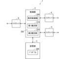
- FIG. 2 is a schematic diagram showing an example of a configuration of a processing apparatus.
- 10 is a flowchart showing an example of an operation of the processing device.
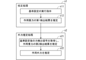
- 4 is a flowchart showing an example of the operation of the control system.
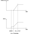
- FIG. 2 is a schematic diagram for explaining an example of an operation of the processing apparatus.
- FIG. 2 is a schematic diagram showing an example of a configuration of a processing apparatus.
- 1 is a schematic diagram showing an example of a holding posture of an end effector (holding mechanism).
- FIG. 1 is a schematic diagram for explaining an example of a processing device 1.
- a force detection signal 21 output by a sensor device 20 that detects a force acting on an end effector 12 whose posture changes is input to the processing device 1.
- the sensor device 20 is fixed to the end effector 12, and the posture of the force sensor 20 changes in response to a change in the posture of the end effector 12.
- the sensor device 20 is capable of detecting a force acting on the end effector 12 from outside the end effector 12.
- the sensor device 20 is capable of detecting an external force, including gravity, acting on the end effector 12.
- the sensor device 20 is capable of detecting gravity acting on the end effector 12 and an external force other than gravity acting on the end effector 12.
- the sensor device 20 outputs a force detection signal 21 indicating the detection result.
- the processing device 1 can remove the effect of gravity acting on the end effector 12, which is included in the force detection signal 21, from the force detection signal 21, and obtain (in other words, estimate or calculate) the external force acting on the end effector 12, excluding gravity.
- a force acting on an object we mean an external force, including gravity, that acts on that object.
- an external force acting on an object we mean an external force, excluding gravity, that acts on that object.
- An external force acting on an object can be said to be a force, excluding gravity, that acts on the object from the outside.
- the end effector 12 may be, for example, a holding mechanism capable of holding an object (also called a held object).
- the sensor device 20 is capable of detecting a force acting on the holding mechanism.
- the end effector 12 may also be something other than a holding mechanism.
- the end effector 12 may be a processing member at the tip of a machine tool.
- the end effector 12 may also be, for example, a member for tightening screws, a member for painting work, a member for welding work, or a member for cutting work.
- the object may be, for example, an industrial product such as an electronic device or a screw, a food product such as vegetables or bread, or a household item such as a diaper, a toothbrush, or a cup.
- FIG. 1 is a schematic diagram showing an example of the configuration of a robot system 100 including the processing device 1 and the robot 10.
- the robot system 100 includes, for example, a robot 10 and a control system 50 that controls the robot 10.
- the control system 50 can also be referred to as, for example, a control device or controller.
- the robot 10 is, for example, an arm-type robot.
- the robot 10 includes, for example, an arm 11, a holding mechanism serving as an end effector 12, and a sensor device 20.
- the end effector 12 is a holding mechanism that holds an object 80.
- the end effector 12 is connected to the arm 11.
- the end effector 12 has, for example, a plurality of fingers, and can grasp the object 80 with the plurality of fingers.
- the end effector 12 includes, for example, a motor that drives the plurality of fingers. The plurality of fingers can grasp the object 80 by being driven by the motor. Note that the end effector 12 may hold the object 80 by suction.
- the arm 11, for example, has at least one joint.
- the arm 11, for example, has a motor that rotates at least one joint.
- the arm 11 can change its posture.
- the posture of the end effector 12 changes in response to the change in posture of the arm 11.
- the robot 10 performs the task of, for example, holding and moving an object 80.
- the robot 10 can move the object 80 by, for example, changing the posture of the arm 11 while holding the object 80 with the end effector 12.
- the robot 10 holds the object 80 placed on a work table 90 with the end effector 12.
- the robot 10 moves the arm 11 to move the held object 80 from the work table 90 to the work table 91.
- the robot 10 then causes the end effector 12 to release its hold on the object 80, and places the object 80 on the work table 91.
- This type of task is sometimes called pick-and-place.
- the work performed by the robot 10 is not limited to the above example.
- the robot 10 may hold and move one object 80 at a time from a pile of multiple objects 80.
- the robot 10 may also hold an object 80 on a work table 90, turn it over, and then place it back on the work table 90.
- the sensor device 20 is capable of detecting a force (also called an acting force) acting on the end effector 12.
- the sensor device 20 repeatedly detects the acting force and repeatedly outputs a force detection signal 21 indicating the detection result of the acting force.
- the sensor device 20 is, for example, a force sensor 20.
- the acting force detected by the force sensor 20 includes gravity acting on the end effector 12 (also called acting gravity) detected by the force sensor 20, and an external force acting on the end effector 12 (also called acting external force) detected by the force sensor 20.
- the force sensor 20 may be, for example, an electrical resistance type, a capacitance type, a piezoelectric type, or an optical type.
- the force sensor 20 is, for example, located between the arm 11 and the end effector 12 and fixed to the end effector 12.
- the relative attitude relationship between the force sensor 20 and the end effector 12 is constant.
- the force sensor 20 can detect gravity acting on the end effector 12, for example, when the end effector 12 is not placed on a surface such as the ground but is in the air.
- the attitude of the force sensor 20 changes in response to changes in the attitude of the end effector 12. Since the attitude of the end effector 12 changes in response to changes in the attitude of the arm 11, the attitude of the force sensor 20 changes in response to changes in the attitude of the arm 11.
- an xyz Cartesian coordinate system is set in the force sensor 20.
- the xyz Cartesian coordinate system set in the force sensor 20 will be referred to as the sensor coordinate system.
- the x-axis direction, y-axis direction, and z-axis direction of the sensor coordinate system will be referred to as the x-direction, y-direction, and z-direction, respectively.
- the attitude of the sensor coordinate system changes in response to changes in the attitude of the force sensor 20. Since the attitude of the force sensor 20 changes in response to changes in the attitude of the end effector 12, the attitude of the sensor coordinate system changes in response to changes in the attitude of the end effector 12. Also, since the attitude of the force sensor 20 changes in response to changes in the attitude of the arm 11, the attitude of the sensor coordinate system changes in response to changes in the attitude of the arm 11.
- the force sensor 20 can detect, for example, the x-direction component of the acting force (also referred to as the x-component of the acting force), the y-direction component of the acting force (also referred to as the y-component of the acting force), and the z-direction component of the acting force (also referred to as the z-component of the acting force).
- the x-component of the acting force detected by the force sensor 20 will be referred to as the detected x-component of the acting force.
- the y-component of the acting force detected by the force sensor 20 will be referred to as the detected y-component of the acting force.
- the z-component of the acting force detected by the force sensor 20 will be referred to as the detected z-component of the acting force.
- the force detection signal 21 output from the force sensor 20 indicates the x-component of the acting force, the y-component of the acting force, and the z-component of the acting force.
- the force sensor 20 can detect, for example, the x-direction component of acting gravity (also referred to as the acting gravity x-component), the y-direction component of acting gravity (also referred to as the acting gravity y-component), and the z-direction component of acting gravity (also referred to as the acting gravity z-component).
- the acting gravity x-component detected by the force sensor 20 will be referred to as the detected acting gravity x-component.
- the acting gravity y-component detected by the force sensor 20 will be referred to as the detected acting gravity y-component.
- the acting gravity z-component detected by the force sensor 20 will be referred to as the detected acting gravity z-component.
- the force sensor 20 can detect, for example, the x-direction component of an acting external force (also referred to as the acting external force x-component), the y-direction component of an acting external force (also referred to as the acting external force y-component), and the z-direction component of an acting external force (also referred to as the acting external force z-component).
- the acting external force x-component detected by the force sensor 20 will be referred to as the detected acting external force x-component.
- the acting external force y-component detected by the force sensor 20 will be referred to as the detected acting external force y-component.
- the acting external force z-component detected by the force sensor 20 will be referred to as the detected acting external force z-component.
- the detectable action force x component includes the detectable action gravity x component and the detectable action external force x component. If the force sensor 20 does not detect the x-direction component of the action gravity, the detectable action gravity is zero. Also, if the force sensor 20 does not detect the x-direction component of the action external force, the detectable action external force is zero.
- the detectable action force y component includes the detectable action gravity y component and the detectable action external force y component
- the detectable action force z component includes the detectable action gravity z component and the detectable action external force z component.
- a reference setting is performed to adjust the reference point of the force detection signal 21.
- the force sensor 20 performs reference setting in response to an execution instruction from the processing device 1.
- Reference setting is also called reference point setting, which sets the reference point of the force detection signal 21.
- Reference setting is also called offset, for example.
- the reference points of the detected action force x component, the detected action force y component, and the detected action force z component are adjusted (in other words, set).
- the force detection signal 21 after reference setting indicates the detected action force x component after reference setting, the detected action force y component after reference setting, and the detected action force z component after reference setting.
- the reference point is also called a zero point, for example, and reference setting is also called zero point setting or zero point adjustment, for example.
- the x-component of the detected action force, the y-component of the detected action force, and the z-component of the detected action force when the reference setting is executed are set to the reference point.
- the x-component of the detected action force, the y-component of the detected action force, and the z-component of the detected action force set to the reference point i.e., the x-component of the detected action force, the y-component of the detected action force, and the z-component of the detected action force when the reference setting is executed, are respectively referred to as the x-component adjustment value, the y-component adjustment value, and the z-component adjustment value.
- the value obtained by subtracting the x-component adjustment value from the detectable action force x-component becomes the detectable action force x-component after the reference is set. Furthermore, the value obtained by subtracting the y-component adjustment value from the detectable action force y-component becomes the detectable action force y-component after the reference is set. Furthermore, the value obtained by subtracting the z-component adjustment value from the detectable action force z-component becomes the detectable action force z-component after the reference is set.
- a detectable action force x-component that does not begin with “after reference is set” does not mean the detectable action force x-component after the reference is set, but the original detectable action force x-component when no reference is set. The same applies to the detectable action force y-component and the detectable action force z-component.
- the detected action force x component after the reference is set indicates the amount of change from the time the reference was set in the detected action force x component (i.e., the original detected action force x component when no reference is set).
- the detected action force x component after the reference is set includes the amount of change from the time the reference was set in the detected action gravity x component.
- the detected action force y component after the reference is set indicates the amount of change in the detected action force y component from when the reference was set.
- the detected action force y component after the reference is set includes the amount of change in the detected action gravity y component from when the reference was set.
- the detectable force z component after the reference is set indicates the amount of change in the detectable force z component from when the reference was set.
- the detectable force z component after the reference is set includes the amount of change in the detectable force gravitational z component from when the reference was set.
- the detected action force x component, detected action force y component, and detected action force z component at the time the reference is set again are set to a new reference point.
- the detected action force x component, detected action force y component, and detected action force z component at the time the reference is set again are set to the x component adjustment value, y component adjustment value, and z component adjustment value, respectively, and the x component adjustment value, y component adjustment value, and z component adjustment value are subtracted from the detected action force x component, action force y component, and action force z component, respectively.
- the offsets contained in the detected action force x component, the detected action force y component, and the detected action force z component are removed.
- the temperature drift appearing in the detected action force x component, the detected action force y component, and the detected action force z component can be reduced.
- the control system 50 that controls the robot 10 includes, for example, a main controller 60 and a processing device 1.
- the processing device 1 functions as, for example, a controller 1 that controls the end effector 12.
- the main controller 60 is, for example, a control device that manages the overall operation of the robot 10.
- the main controller 60 is also called, for example, a robot controller.
- the main controller 60 is capable of controlling the arm 11.
- the main controller 60 is also capable of controlling the end effector 12 through the processing device 1.
- the main controller 60 can also be called a processing device.
- the processing device 1 can control the holding of the object 80 by the end effector 12.
- the processing device 1 can cause the end effector 12 to hold the object 80 or release the holding of the object 80.
- the processing device 1 can also control the holding force of the object 80 by the end effector 12.
- the processing device 1 can adjust the holding force of the object 80 by adjusting the spacing between the multiple fingers of the end effector 12 that hold the object 80.
- Fig. 3 is a schematic diagram showing an example of the configuration of the processing device 1.
- the processing device 1 is, for example, a computer device. As shown in Fig. 3, the processing device 1 includes, for example, a control unit 2, a storage unit 3, an interface 4, an interface 5, and an interface 6.
- the processing device 1 can also be said to be, for example, a processing circuit.
- the interface 6 is capable of communicating with the main controller 60.
- the interface 6 may communicate with the main controller 60 via wired or wireless communication.
- the interface 6 may also be referred to as, for example, an interface circuit, a communication unit, or a communication circuit. Instructions and notifications given by the main controller 60 to the processing device 1 are input to the control unit 2 via the interface 6. In addition, the control unit 2 can send notifications to the main controller 60 via the interface 6.
- the interface 4 is capable of communicating with the force sensor 20.
- the interface 4 may communicate with the force sensor 20 via wired or wireless communication.
- the interface 4 may also be referred to as, for example, an interface circuit, a communication unit, or a communication circuit.
- the force detection signal 21 that the interface 4 receives from the force sensor 20 is input to the control unit 2.
- the interface 5 can drive the end effector 12 in response to an instruction from the control unit 2.
- the interface 5 can also be called, for example, an interface circuit or a drive circuit.
- the interface 5 can drive, for example, a motor provided in the end effector 12.
- the control unit 2 is capable of managing the overall operation of the processing device 1 by controlling the other components of the processing device 1.
- the control unit 2 can be, for example, a control circuit.
- the control unit 2 includes at least one processor to provide control and processing power to perform various functions, as described in more detail below.
- the at least one processor may be implemented as a single integrated circuit (IC) or as multiple communicatively connected integrated circuits ICs and/or discrete circuits.
- the at least one processor may be implemented according to various known techniques.
- a processor includes one or more circuits or units configured to perform one or more data computation procedures or processes, e.g., by executing instructions stored in associated memory.
- a processor may be firmware (e.g., discrete logic components) configured to perform one or more data computation procedures or processes.
- the processor may include one or more processors, controllers, microprocessors, microcontrollers, application specific integrated circuits (ASICs), digital signal processors, programmable logic devices, field programmable gate arrays, or any combination of these devices or configurations, or other known devices and configurations, to perform the functions described below.
- ASICs application specific integrated circuits
- digital signal processors programmable logic devices, field programmable gate arrays, or any combination of these devices or configurations, or other known devices and configurations, to perform the functions described below.
- the control unit 2 may, for example, include a CPU (Central Processing Unit) as a processor.
- the memory unit 3 may include a non-transitory recording medium readable by the CPU of the control unit 2, such as a ROM (Read Only Memory) and a RAM (Random Access Memory).
- the memory unit 3 stores, for example, a program 300 for controlling the processing device 1.
- the various functions of the control unit 2 are realized, for example, by the CPU of the control unit 2 executing the program 300 in the memory unit 3.
- control unit 2 may include multiple CPUs.
- the control unit 2 may also include at least one DSP (Digital Signal Processor). All or some of the functions of the control unit 2 may be realized by a hardware circuit that does not require software to realize the function.
- the memory unit 3 may also include a computer-readable non-transitory recording medium other than ROM and RAM.
- the memory unit 3 may include, for example, a small hard disk drive and an SSD (Solid State Drive).
- the main controller 60 may have a configuration similar to that of the processing device 1.
- the main controller 60 may have a control unit similar to the control unit 2, a memory unit similar to the memory unit 3, an interface for communicating with the processing device 1, and an interface for driving the arm 11.
- the control unit 2 executes an external force estimation process to estimate an acting external force based on the force detection signal 21.
- the external force estimation process can also be said to be a process in which an external force acting on the end effector 12 is detected from the force detection signal 21.
- the control unit 2 is capable of detecting the acting external force from the force detection signal 21.
- the control unit 2 controls the holding force of the object 80 by the end effector 12 based on the acting external force estimated in the external force estimation process.
- a holding control unit 200 and an acquisition unit 250 are formed as functional blocks in the control unit 2.
- the holding control unit 200 controls the holding of the object 80 by the end effector 12 through the interface 5.
- the acquisition unit 250 estimates (in other words, detects) the acting external force from the force detection signal 21 received by the interface 4.
- the acquisition unit 250 has, for example, a first estimation unit 210 and a second estimation unit 220.
- the first estimation unit 210 estimates (in other words, calculates) the detection result of the acting gravity detected by the force sensor 20 when the reference is set.
- the second estimation unit 220 estimates (in other words, calculates) the acting external force based on the force detection signal 21 after the reference is set and the estimation result by the first estimation unit 210, etc.
- All or some of the functions of the retention control unit 200 may be realized by a hardware circuit that does not require software to realize the function. The same applies to the acquisition unit 250, the first estimation unit 210, and the second estimation unit 220.
- FIG. 4 is a flowchart showing an example of the operation of the control unit 2. As shown in FIG. 4, after the calibration process in step s1 is executed, the external force estimation process in step s2 is executed. The calibration process can also be considered as a preparatory process for estimating the acting external force.
- the control unit 2 instructs the force sensor 20 to execute reference setting through the interface 4.
- the control unit 2 instructs the force sensor 20 to execute reference setting when no external force is acting on the end effector 12.
- reference setting is performed when no external force is acting on the end effector 12.
- the force sensor 20, which has received the execution instruction from the control unit 2 sets the reference.
- the force sensor 20 outputs a force detection signal 21 after reference setting.
- the attitude of the end effector 12 when reference setting is performed in other words, the attitude of the end effector 12 when the control unit 2 instructs the force sensor 20 to execute reference setting
- the reference setting attitude is not limited to a specific attitude and may be any attitude.
- the first estimation unit 210 estimates a first detection result of the acting gravity component detected by the force sensor 20 when the reference is set.
- the first estimation unit 210 estimates a first detection result of the acting gravity detected by the force sensor 20 when the end effector 12 is in a reference setting posture with no external force acting on it.
- the first detection result includes a detected acting gravity x component, a detected acting gravity y component, and a detected acting gravity z component.
- the first estimation unit 210 estimates the first detection result by calculating first predicted values of the detected acting gravity x component, the detected acting gravity y component, and the detected acting gravity z component when the reference is set.
- the first estimation unit 210 estimates the first detection result based on the posture of the end effector 12 at the time of setting the reference, the weight of the end effector 12, and the gravitational acceleration. In other words, the first estimation unit 210 determines first predicted values of the detected action gravity x component, the detected action gravity y component, and the detected action gravity z component based on the posture at the time of setting the reference, the weight of the end effector 12, and the gravitational acceleration.
- the first estimation unit 210 obtains the component of gravity acting on the end effector 12 in the x direction at the time of reference setting based on the weight of the end effector 12 and the gravitational acceleration, and sets the obtained value as the predicted value of the detected action gravity x component.
- the first estimation unit 210 also obtains the component of gravity acting on the end effector 12 in the y direction at the time of reference setting based on the weight of the end effector 12 and the gravitational acceleration, and sets the obtained value as the predicted value of the detected action gravity y component.
- the first estimation unit 210 also obtains the component of gravity acting on the end effector 12 in the z direction at the time of reference setting based on the weight of the end effector 12 and the gravitational acceleration, and sets the obtained value as the predicted value of the detected action gravity z component.
- the first predicted values of the detected action gravity x component, the detected action gravity y component, and the detected action gravity z component calculated by the first estimation unit 210 can be said to be multiple first decomposed components of the gravity of the end effector 12 itself acting on the end effector 12 in the reference setting posture (in other words, the first posture).
- the first estimation unit 210 can recognize the reference-setting posture of the end effector 12. For example, consider a case where an acceleration sensor that detects the posture of the end effector 12 is provided on the end effector 12. In this case, the first estimation unit 210 acquires the detection result from the acceleration sensor in step s12, for example, and identifies the current posture of the end effector 12 based on the acquired detection result. The first estimation unit 210 then uses the identified posture as the reference-setting posture.
- the first estimation unit 210 may also be notified of the current posture of the end effector 12 from the main controller 60 that controls the posture of the arm 11.
- the main controller 60 repeatedly identifies the current posture of the end effector 12 and repeatedly notifies the processing device 1 of the identified current posture.
- the main controller 60 that controls the arm 11 can, for example, identify the current posture of the end effector 12 based on the current posture of the arm 11.
- the first estimation unit 210 uses the current posture of the end effector 12 that the main controller 60 notifies the processing device 1 of in step s12 as the reference setting posture.
- step S12 When step S12 is executed and the calibration process is completed, the external force estimation process is executed.
- the external force estimation process may be executed immediately after the calibration process is executed, or may be executed some time after the calibration process is executed. Furthermore, the external force estimation process may be executed multiple times after the calibration process.
- the second estimation unit 220 acquires the force detection signal 21 output by the force sensor 20 after the reference has been set. Also, in step s21, the second estimation unit 220 estimates the second detection result of the acting gravitational force currently detected by the force sensor 20.
- the posture of the end effector 12 when the external force estimation process is executed is referred to as the posture at the time of external force estimation or the second posture.
- the posture at the time of external force estimation is the posture of the end effector 12 after the reference has been set.
- the second estimation unit 220 can also be said to estimate the second detection result of the acting gravity detected by the force sensor 20 when the end effector 12 is in the external force estimation posture.
- the second estimation unit 220 can also be said to estimate the second detection result of the acting gravity detected by the force sensor 20 when the external force estimation process is executed (also referred to as when the external force is estimated).
- the second estimation unit 220 can also be said to estimate the second detection result of the acting gravity detected by the force sensor 20 when the acting external force is estimated.
- the posture when estimating an external force is not limited to a specific posture and may be any posture.
- the posture when estimating an external force may be the same as the posture when the reference is set, or may be different from the posture when the reference is set.
- the second detection result includes a detected action gravity x component, a detected action gravity y component, and a detected action gravity z component.
- the second estimation unit 220 estimates the current second detection result of the force sensor 20 by determining second predicted values of the current detected action gravity x component, detected action gravity y component, and detected action gravity z component of the force sensor 20. In other words, the second estimation unit 220 estimates the second detection result at the time of external force estimation by determining second predicted values of the detected action gravity x component, detected action gravity y component, and detected action gravity z component at the time of external force estimation.
- the second estimation unit 220 estimates a second detection result at the time of external force estimation based on the posture of the end effector 12 at the time of external force estimation, the weight of the end effector 12, and the gravitational acceleration. That is, the second estimation unit 220 calculates second predicted values of the detected action gravity x component, the detected action gravity y component, and the detected action gravity z component at the time of external force estimation based on the posture of the end effector 12 at the time of external force estimation, the weight of the end effector 12, and the gravitational acceleration. In step s21, the second estimation unit 220 may identify the current posture of the end effector 12 based on the detection result of the acceleration sensor provided on the end effector 12, and use the identified posture as the posture at the time of external force estimation.
- the second estimation unit 220 may use the current posture of the end effector 12 notified by the main controller 60 as the posture at the time of external force estimation.
- the method for calculating the second predicted values of the detected action gravity x component, the detected action gravity y component, and the detected action gravity z component is the same as the method for calculating the first predicted values of the detected action gravity x component, the detected action gravity y component, and the detected action gravity z component in step S12.
- the second estimation unit 220 estimates the acting external force currently acting on the end effector 12. In other words, the second estimation unit 220 estimates the acting external force acting on the end effector 12 in the posture at the time of external force estimation. In further other words, the second estimation unit 220 estimates the acting external force acting on the end effector 12 at the time of external force estimation. The second estimation unit 220 estimates the acting external force currently acting on the end effector 12 based on the force detection signal 21 acquired in step s21, the estimated second detection result, and the first detection result estimated by the first estimation unit 210 in step s12.
- the second estimation unit 220 predicts the acting external force by calculating predicted values of the x-direction component, y-direction component, and z-direction component of the acting external force currently acting on the end effector 12. It can also be said that the second estimation unit 220 estimates the acting external force acting on the end effector 12 in the posture when the external force is estimated, based on the force detection signal 21 when the end effector 12 is in the posture when the external force is estimated, the estimated second detection result, and the first detection result estimated in step s12.
- the first detection result estimated by the first estimation unit 210 that is, the first predicted values of the detected action gravity x component, the detected action gravity y component, and the detected action gravity z component (in other words, the multiple first resolved components) are respectively designated as Fg1x, Fg1y, and Fg1z.
- the second detection result estimated by the second estimation unit 220 that is, the second predicted values of the detected action gravity x component, the detected action gravity y component, and the detected action gravity z component (in other words, the multiple second resolved components)
- Fg2x, Fg2y, and Fg2z the first detection result estimated by the first estimation unit 210
- the second detection result estimated by the second estimation unit 220 that is, the second predicted values of the detected action gravity x component, the detected action gravity y component, and the detected action gravity z component
- the detected action force x component after reference setting, the detected action force y component after reference setting, and the detected action force z component after reference setting indicated by the force detection signal 21 acquired in step s21 are respectively designated as Fmx, Fmy, and Fmz.
- the predicted values of the x-direction component, y-direction component, and z-direction component of the external force currently acting on the end effector 12 are Fox, Foy, and Foz, respectively.
- the second estimation unit 220 calculates Fox, Foy, and Foz using the following formula (1).
- Fmx includes the amount of change in the currently detected acting gravity x component since the reference was set. Therefore, the value obtained by adding Fmx to the first predicted value Fg1x of the detected acting gravity x component at the time of the reference setting includes a value equivalent to the currently detected acting gravity x component and the x-direction component of the currently acting external force. Therefore, the value obtained by subtracting the second predicted value Fg2x of the currently detected acting gravity x component from the value obtained by adding Fmx to Fg1x is a value equivalent to the x-direction component of the currently acting external force (in other words, the acting external force acting on the end effector 12 at the time of external force estimation). In other words, (Fg1x + Fmx - Fg2x) can be said to be the predicted value Fox of the x-direction component of the currently acting external force.
- the value obtained by subtracting the second predicted value Fg2y of the currently detected gravitational force y-component from the value obtained by adding Fg1y to Fmy is a value equivalent to the y-direction component of the currently acting external force.
- (Fg1y + Fmy - Fg2y) can be said to be the predicted value Foy of the y-direction component of the currently acting external force.
- the value obtained by subtracting the second predicted value Fg2z of the currently detected acting gravitational z-component from the value obtained by adding Fmz to Fg1z corresponds to the z-component of the currently acting external force.
- (Fg1z + Fmz - Fg2z) can be said to be the predicted value Foz of the z-component of the currently acting external force.
- the first estimation unit 210 may read out the weight corresponding to the type of end effector 12 currently being controlled from the memory unit 3 and use it in step s12.
- effector type information indicating the type of end effector 12 currently equipped to the robot 10 is stored in the memory unit 3.
- the first estimation unit 210 can identify the type of end effector 12 currently equipped to the robot 10 based on the effector type information in the memory unit 3.
- the type of end effector 12 currently equipped to the robot 10 may also be notified to the processing device 1 from the main controller 60.
- posture identification information for identifying the posture at the time of setting the reference may be stored in the storage unit 3.
- the first estimation unit 210 may use the posture identification information in the storage unit 3 to execute step s12 at a timing different from the time of setting the reference, unlike the example of FIG. 4.
- the first estimation unit 210 may execute step s12 some time after the reference is set.
- FIG. 5 is a flowchart showing an example of the operation of the control system 50 when the calibration process and external force estimation process are performed when the robot 10 picks and places an object 80 on the work table 90.
- step s51 the main controller 60 of the control system 50 controls the movement of the arm 11 to move the end effector 12 to an initial position.
- the initial position is set, for example, above the object 80 on the work table 90.
- step s52 the main controller 60 controls the movement of the arm 11 to bring the end effector 12 closer to the object 80 on the work table 90. Specifically, the main controller 60 controls the movement of the arm 11 to bring the end effector 12 closer to the object 80 so that the object 80 is positioned between the multiple fingers of the end effector 12. Then, in step s53, the main controller 60 issues an instruction to the processing device 1 to cause the end effector 12 to hold the object 80 (also referred to as a holding execution instruction).
- the processing device 1 that has received the instruction to perform holding, the above-mentioned step s1 is executed, and the calibration process is performed.
- the holding control unit 200 causes the end effector 12 to hold the target object 80, a reference is set and the first detection result of the acting gravity at the time of setting the reference is estimated.
- step S54 the main controller 60, having received the holding completion notification, causes the robot 10 to start moving the object 80 held by the end effector 12 to the work table 91.
- the main controller 60 controls the movement of the arm 11 to cause the robot 10 to move the object 80 to the work table 91.
- the robot 10 moves the object 80 on the work table 90 to the work table 91, it first lifts the object 80 from the work table 90. The robot 10 then moves the lifted object 80 to the work table 91.
- step s2 is executed to execute the external force estimation process.
- the external force currently acting on the end effector 12 is estimated.
- the processing device 1 repeatedly executes the external force estimation process until the robot 10 lifts the object 80 from the work table 90 and the object 80 leaves the work table 90.
- the second estimation unit 220 estimates the acting external force acting on the end effector 12 multiple times from when the object 80 is held by the end effector 12 until the object 80 is lifted.
- the second estimation unit 220 estimates the acting external force acting on the end effector 12 at each of multiple timings from when the object 80 is held by the end effector 12 until the object 80 is lifted.
- the second estimation unit 220 uses the first detection result estimated in the calibration process immediately after step s53 in each of the multiple external force estimation processes performed while the object 80 is being lifted after the object 80 is held by the end effector 12.
- the second estimation unit 220 determines whether or not the robot 10 has completed lifting the object 80 in step s63 each time it executes the external force estimation process. Then, when the second estimation unit 220 determines that the robot 10 has completed lifting the object 80 (YES in step s63), in other words, that the object 80 has left the worktable 90, it ends the repeated execution of the external force estimation process.
- the holding control unit 200 may control the holding force of the object 80 at the end effector 12 based on the acting external force estimated by the second estimation unit 220 while the object 80 is being lifted after the object 80 is held by the end effector 12. In other words, the holding control unit 200 may control the holding force of the object 80 at the end effector 12 based on the acting external force repeatedly estimated by the second estimation unit 220 after step s61 is executed until YES is determined in step s63.
- the holding force simply refers to the holding force of the object 80 at the end effector 12.
- FIG. 6 is a schematic diagram for explaining an example of holding force control by the holding control unit 200.
- the graph shown in the upper part of FIG. 6 is a graph showing an example of how the magnitude of the external force acting on the end effector 12 changes from when the object 80 is held by the end effector 12 until the object 80 is lifted.
- the graph shown in the lower part of FIG. 6 is a graph showing an example of how the holding force is controlled from when the object 80 is held by the end effector 12 until the object 80 is lifted. In this example, from when the object 80 is held by the end effector 12 until the object 80 is lifted, only the external force due to the weight of the object 80 held by it and gravity act on the end effector 12.
- the second estimation unit 220 obtains the magnitude of the acting external force estimated by the external force estimation process each time the external force estimation process is performed.
- the magnitude of the resultant vector of the predicted values of the x-direction component, y-direction component, and z-direction component of the acting external force obtained by the external force estimation process becomes the magnitude of the acting external force estimated by the external force estimation process.
- the second estimation unit 220 determines that lifting of the object 80 is complete (YES in step s63) and ends the repeated execution of the external force estimation process.
- the holding control unit 200 may gradually increase the holding force in response to a gradual increase in the magnitude of the acting external force estimated by the second estimation unit 220 while the object 80 is being lifted after the object 80 is held by the end effector 12. This makes it less likely that the object 80 will fall off the end effector 12 when the robot 10 lifts the object 80 held by the end effector 12.
- the posture in which the end effector 12 holds the object 80 is not limited to a specific posture and may be any posture. Furthermore, the posture of the end effector 12 when the robot 10 lifts the object 80 held by the end effector 12 is not limited to a specific posture and may be any posture.
- step s64 upon receiving the hold release command, the processing device 1 causes the hold control unit 200 to cause the end effector 12 to release the object 80. This ends the pick-and-place operation.
- the control system 50 can operate in the same manner as in the example of FIG. 5.
- the robot system 100 is equipped with a camera that captures the multiple objects 80 piled up randomly.
- the main controller 60 determines an object 80 to be a work object from among the multiple objects 80 piled up randomly based on a camera image obtained by the camera.
- the main controller 60 determines from which direction the end effector 12 will approach the object 80 determined as the work object based on the camera image. In other words, the main controller 60 determines the approach direction of the end effector 12 with respect to the object 80 determined as the work object based on the camera image.
- the holding posture in which the end effector 12 approaches and holds the object 80 is determined. Then, the main controller 60 controls the movement of the arm 11 to move the end effector 12 toward the object 80 from the determined approach direction. After that, steps s53, s1, and s61 are executed, and the end effector 12 holds the object 80. Thereafter, the control system 50 operates in the same manner.
- the external force estimation process may be repeatedly executed from when the end effector 12 holds the object 80 until the object 80 moves and the end effector 12 releases its hold on the object 80. In this case, step s63 may not be executed.
- the holding control unit 200 may control the holding force of the object 80 in the end effector 12 based on the acting external force estimated by the second estimation unit 220 from when the end effector 12 holds the object 80 until the end effector 12 releases its hold on the object 80.
- the second attitude in the external force estimation process (in other words, the attitude at the time of external force estimation) may change due to a change in the attitude of the end effector 12 while the object 80 is moving. In other words, when the attitude of the end effector 12 changes, the external force estimation process may be repeatedly executed.
- the acquisition unit 250 acquires the external force acting on the end effector 12 based on multiple first resolved components of the gravity of the end effector 12 itself acting on the end effector 12 in the reference setting posture (in other words, the first posture), multiple second resolved components of the gravity of the end effector 12 itself acting on the end effector 12 in the posture when an external force is applied (in other words, the second posture), and the force detection signal 21 when an external force is applied to the end effector 12.
- This allows the processing device 1 to appropriately acquire the external force acting on the end effector 12 (i.e., a force acting on the end effector 12 from the outside, excluding gravity). This improves the convenience of the processing device 1.
- the reference setting posture and external force estimation posture of the end effector 12 are not limited to a specific posture, so the processing device 1 can obtain the external force acting on the end effector 12 without being restricted by the posture of the end effector 12.
- the processing device 1 can repeatedly set the reference without being restricted by the posture of the end effector 12, thereby reducing the influence of temperature drift appearing in the detection results of the force sensor 20.
- the end effector 12 is the end effector 12 of a robot 10
- the reference can be repeatedly set without interrupting the work of the robot 10, thereby reducing the influence of temperature drift appearing in the detection results of the force sensor 20. Therefore, the work efficiency of the robot 10 can be improved.
- the holding control unit 200 controls the holding force of the object 80 at the end effector 12 based on the acting external force estimated by the second estimation unit 220 while the object 80 is held by the end effector 12, thereby making it difficult for the object 80 to fall from the end effector 12.
- the reference setting is performed before the holding control unit 200 causes the end effector 12 to hold the object 80.
- the end effector 12 holds the object 80, external forces are unlikely to act on the end effector 12. Therefore, by setting the reference before the object 80 is held, it is possible to reliably perform the reference setting when no external forces are acting on the end effector 12.
- the force sensor 20 sets the reference, but the control unit 2 of the processing device 1 may set the reference.
- the control unit 2 sets the detected action force x component, detected action force y component, and detected action force z component indicated by the latest force detection signal 21 output from the force sensor 20 as the reference points, and sets the reference.
- the control unit 2 sets the detected action force x component, detected action force y component, and detected action force z component indicated by the latest force detection signal 21 output from the force sensor 20 as the x component adjustment value, y component adjustment value, and z component adjustment value, respectively.
- the control unit 2 sets the value obtained by subtracting the x component adjustment value from the detected action force x component indicated by the force detection signal 21 from the force sensor 20 as the detected action force x component indicated by the force detection signal 21 after the reference is set (i.e., the detected action force x component after the reference is set). Furthermore, after setting the reference, the control unit 2 sets the value obtained by subtracting the y-component adjustment value from the detected action force y component indicated by the force detection signal 21 from the force sensor 20 as the detected action force y component indicated by the force detection signal 21 after setting the reference (i.e., the detected action force y component after setting the reference).
- control unit 2 sets the value obtained by subtracting the z-component adjustment value from the detected action force z component indicated by the force detection signal 21 from the force sensor 20 as the detected action force z component indicated by the force detection signal 21 after setting the reference (i.e., the detected action force z component after setting the reference).
- the external force estimation process may be executed after the object 80 is lifted.
- the external force estimation process may be executed at least once from when the object 80 is lifted until the object 80 moves to the work table 91.
- the control unit 2 may notify the main controller 60 of an error through the interface 6 when the magnitude of the acting external force estimated by the second estimation unit 220 becomes equal to or exceeds a threshold value, for example, when the end effector 12 collides with an obstacle.
- the main controller 60 that receives the error notification may stop the movement of the arm 11 and stop the robot 10.
- the external force estimation process may also be performed when the end effector 12 is not holding an object 80.
- the external force estimation process may be performed at least once when the end effector 12 places an object 80 on the work table 91 and then moves to an initial position to hold the next object 80.
- the control unit 2 may notify the main controller 60 of an error via the interface 6 when the magnitude of the acting external force estimated by the second estimation unit 220 becomes equal to or exceeds a threshold value, for example, when the end effector 12 collides with an obstacle.
- the second estimation unit 220 may also estimate the acting external force acting on the end effector 12 in each of a plurality of different postures of the end effector 12. For example, consider a case where the posture of the end effector 12 changes when the robot 10 moves the object 80 held by the end effector 12 to the work table 91. In this case, the second estimation unit 220 may estimate the acting external force acting on the end effector 12 in each of a plurality of postures that the end effector 12 shows when the object 80 is moving. In other words, the second estimation unit 220 may estimate the acting external force acting on the end effector 12 in each of a plurality of second postures that the end effector 12 shows when the object 80 is moving.
- the acquisition unit 250 of the control unit 2 may acquire the weight of the object 80 based on the acting external force estimated by the second estimation unit 220.
- FIG. 7 is a schematic diagram showing an example of the configuration of the processing device 1 in this case.
- the acquisition unit 250 includes a weight estimation unit 230 that performs a weight estimation process to estimate the weight of the object 80 based on the acting external force estimated by the second estimation unit 220.
- the weight estimation process can also be said to be a weight acquisition process to acquire the weight of the object 80.
- the weight estimation unit 230 is a functional block that is realized by the CPU of the control unit 2 executing the program 300 in the storage unit 3. Note that all of the functions of the weight estimation unit 230 or some of the functions of the weight estimation unit 230 may be realized by a hardware circuit that does not require software to realize the function.
- the weight estimation unit 230 may perform the weight estimation process, for example, after the robot 10 lifts the object 80 held by the end effector 12. In this case, after the object 80 is lifted, an external force/weight estimation process consisting of an external force estimation process and a weight estimation process is executed. In the external force/weight estimation process, the weight estimation unit 230 estimates the weight of the object 80 by dividing the magnitude of the acting external force estimated in the external force/weight estimation process by the magnitude of the gravitational acceleration, and using this value as an estimate of the weight of the object 80.
- the control unit 2 may notify the main controller 60 of an error through the interface 6 if the weight estimated in the external force/weight estimation process is smaller than the first threshold value and thus too small.
- the control unit 2 may also notify the main controller 60 of an error through the interface 6 if the weight estimated in the external force/weight estimation process is larger than a second threshold value that is larger than the first threshold value and thus too large.
- the weight estimation unit 230 may also execute the weight estimation process multiple times. In this case, for example, after the object 80 is lifted, the external force/weight estimation process consisting of the external force estimation process and the weight estimation process may be executed multiple times.
- the control unit 2 may also estimate the weight of the object 80 based on the force detection signal 21 when the end effector 12 is in each of a plurality of different holding postures in which the end effector 12 holds the object 80.
- the control unit 2 functions as an estimation unit that estimates the weight of the object 80 based on the force detection signal 21 when the end effector 12 is in each of a plurality of holding postures. An example of this will be described below.
- the approach direction of the end effector 12 to a first object 80 (also referred to as first object 80a) included in the plurality of objects 80, the approach direction of the end effector 12 to a second object 80 (also referred to as second object 80b) included in the plurality of objects 80, and the approach direction of the end effector 12 to a third object 80 (also referred to as third object 80c) included in the plurality of objects 80 are different from each other.
- the first holding posture in which the end effector 12 approaches the first object 80a and holds the first object 80a, the second holding posture in which the end effector 12 approaches the second object 80b and holds the second object 80b, and the third holding posture in which the end effector 12 approaches the third object 80c and holds the third object 80c are different from each other.
- FIG. 8 is a schematic diagram showing an example of an end effector 12 in a first holding posture, an end effector 12 in a second holding posture, and an end effector 12 in a third holding posture.
- An example of an end effector 12 in a first holding posture is shown in the upper part of FIG. 8
- an example of an end effector 12 in a second holding posture is shown in the center of FIG. 8
- an example of an end effector 12 in a third holding posture is shown in the lower part of FIG. 8.
- the external force/weight estimation process is executed after the first object 80a is lifted.
- the second estimator estimates the acting external force
- the weight estimator 230 estimates the weight of the first object 80a based on the acting external force estimated by the second estimator 220.
- an external force/weight estimation process is executed after the second object 80b is lifted.
- the second estimator 220 estimates the acting external force
- the weight estimator 230 estimates the weight of the second object 80b based on the acting external force estimated by the second estimator 220.
- an external force/weight estimation process is executed after the third object 80c is lifted.
- the second estimator 220 estimates the acting external force
- the weight estimator 230 estimates the weight of the third object 80c based on the acting external force estimated by the second estimator 220.
- control unit 2 may estimate the weight of the object 80 when the end effector 12 is in each of a plurality of different holding postures that the end effector 12 exhibits while the object 80 is moving.
- control unit 2 can estimate the weight of the object 80 held by the end effector 12 regardless of the holding posture of the end effector 12, thereby improving the convenience of the processing device 1.
- the processing device 1 functioning as a controller controlling the end effector 12 performs the calibration process and the external force estimation process, but the main controller 60 may perform the calibration process and the external force estimation process. That is, the control unit of the main controller 60 may function as the first estimation unit 210 and the second estimation unit 220 of the processing device 1.
- the main controller 60 communicates with the force sensor 20 and receives a force detection signal 21 from the force sensor 20. Then, the main controller 60 notifies the processing device 1 of the acting external force estimated in the external force estimation process.
- the holding control unit 200 of the control unit 2 controls the holding force of the object 80 at the end effector 12 based on the acting external force estimated by the main controller 60.
- the main controller 60 may also perform the calibration process, the external force estimation process, and the weight estimation process. That is, the control unit of the main controller 60 may function as the first estimation unit 210, the second estimation unit 220, and the weight estimation unit 230 of the processing device 1.
- the holding control unit 200 can immediately obtain the estimated result of the acting external force, compared to when the main controller 60 estimates the acting external force. Therefore, in the example of FIG. 3, the holding control unit 200 can, for example, control the holding force in real time according to the estimated acting external force.
- the processing device 1 may be a cloud server 1.
- the cloud server 1 may transmit information on the detected (or estimated) acting external force (also called acting external force information) to a device other than the cloud server 1, and the device may control the holding force of the end effector 12 based on the received acting external force information.
- the main controller 60 may be a cloud server.
- the end effector 12 holds an object, but the object held by the end effector 12 may be a living being such as a human or an animal.
- the robot 10 is an arm-type robot, but this is not limited to this.
- the robot 10 may be a nursing robot or a remote-controlled robot.
- the robot 10 may also be a humanoid robot.
- This disclosure includes the following:
- the processing device includes a control unit that detects an external force acting on the end effector from a force detection signal output from a sensor device, and the control unit has an acquisition unit that acquires the external force acting on the end effector based on a plurality of first resolved components of the gravity of the end effector itself acting on the end effector in a first posture that is the posture when the sensor device is set to a reference position, a plurality of second resolved components of the gravity of the end effector itself acting on the end effector in a second posture that is the posture of the end effector when the external force acts on the end effector, and the force detection signal when the external force acts on the end effector.
- the acquisition unit acquires the external force acting on the end effector in each of a plurality of second postures of the end effector that are different from one another.
- the acquisition unit determines the magnitude of the external force.
- the end effector is a holding mechanism capable of holding an object.
- the acquisition unit acquires the weight of the object based on the external force acquired when the holding mechanism is holding the object.
- the acquisition unit acquires the weight for each of a plurality of different holding positions in which the holding mechanism holds the object.
- a holding control unit is provided that controls the holding of the object by the holding mechanism.
- the holding control unit controls the holding force of the object in the holding mechanism based on the external force acquired by the acquisition unit.
- the acquisition unit acquires the external force acting on the holding mechanism multiple times, and the holding control unit controls the holding force based on the external force acquired by the acquisition unit.
- the robot system includes any one of the processing devices (1) to (10) above and a robot having the end effector that is controlled based on the external force acquired by the processing device.
- the end effector is an end effector that is controlled based on the external force acquired by any one of the processing devices (1) to (10) above.
- the processing device includes an estimation unit that estimates the weight of the object when the holding mechanism is in each of a plurality of different holding positions in which the holding mechanism holds the object based on a force detection signal output by a force sensor that detects the force acting on the holding mechanism.
- the program is intended to cause a computer device to function as any one of the processing devices described above in (1) to (10) and (13).
Landscapes
- Engineering & Computer Science (AREA)
- Human Computer Interaction (AREA)
- Robotics (AREA)
- Mechanical Engineering (AREA)
- Manipulator (AREA)
Abstract
Description
ロボット10は、例えば、アーム型ロボットである。ロボット10は、例えば、アーム11と、エンドエフェクタ12としての保持機構と、センサデバイス20とを備える。エンドエフェクタ12は、対象物80を保持する保持機構である。エンドエフェクタ12はアーム11に接続されている。エンドエフェクタ12は、例えば、複数の指部を有しており、当該複数の指部で対象物80を把持することができる。エンドエフェクタ12は、例えば、複数の指部を駆動するモータを備える。複数の指部は、モータで駆動されることによって、対象物80を把持することができる。なお、エンドエフェクタ12は対象物80を吸引して保持してもよい。
ロボット10を制御する制御システム50は、例えば、メインコントローラ60と、処理装置1とを備える。処理装置1は、例えば、エンドエフェクタ12を制御するコントローラ1として機能する。
図3は処理装置1の構成の一例を示す概略図である。処理装置1は、例えばコンピュータ装置である。処理装置1は、図3に示されるように、例えば、制御部2と、記憶部3と、インタフェース4と、インタフェース5と、インタフェース6とを備える。処理装置1は、例えば処理回路ともいえる。
制御部2は、力検出信号21に基づいて作用外力を推定する外力推定処理を実行する。外力推定処理は、力検出信号21から、エンドエフェクタ12に作用する外力が検出される処理であるともいえる。制御部2は、力検出信号21から作用外力を検出することが可能である。制御部2は、外力推定処理で推定した作用外力に基づいて、エンドエフェクタ12での対象物80の保持力を制御する。

12 エンドエフェクタ
20 センサデバイス
21 力検出信号
60 メインコントローラ
80 対象物
100 ロボットシステム
250 取得部
Claims (13)
- センサデバイスから出力される力検出信号から、エンドエフェクタに作用する外力を検出する制御部を備え、
前記制御部は、
前記センサデバイスの基準設定時の姿勢である第1姿勢の前記エンドエフェクタに作用する前記エンドエフェクタ自体の重力の複数の第1分解成分と、
前記エンドエフェクタの前記外力の作用時の姿勢である第2姿勢の前記エンドエフェクタに作用する前記エンドエフェクタ自体の重力の複数の第2分解成分と、
前記エンドエフェクタの前記外力の作用時の前記力検出信号と、に基づいて、前記エンドエフェクタに作用する前記外力を取得する取得部を有する、処理装置。 - 請求項1に記載の処理装置であって、
前記取得部は、前記エンドエフェクタの互いに異なる複数の第2姿勢のそれぞれについて、当該第2姿勢の前記エンドエフェクタに作用する前記外力を取得する、処理装置。 - 請求項1または請求項2に記載の処理装置であって、
前記取得部は、前記外力の大きさを求める、処理装置。 - 請求項1から請求項3のいずれか一つに記載の処理装置であって、
前記エンドエフェクタは、対象を保持することが可能な保持機構である、処理装置。 - 請求項4に記載の処理装置であって、
前記取得部は、前記保持機構が前記対象を保持しているときに取得した前記外力に基づいて、前記対象の重量を取得する、処理装置。 - 請求項5に記載の処理装置であって、
前記取得部は、前記保持機構が前記対象を保持する、互いに異なる複数の保持姿勢のそれぞれについて、前記重量を取得する、処理装置。 - 請求項4から請求項6のいずれか一つに記載の処理装置であって、
前記保持機構での前記対象の保持を制御する保持制御部を備える、処理装置。 - 請求項7に記載の処理装置であって、
前記処理装置が前記保持機構での前記対象の保持の実行指示を受けた場合、前記保持制御部が前記保持機構に前記対象を保持させる前に、前記基準設定が行われる、処理装置。 - 請求項7または請求項8に記載の処理装置であって、
前記保持制御部は、前記取得部で取得された前記外力に基づいて、前記保持機構での前記対象の保持力を制御する、処理装置。 - 請求項9に記載の処理装置であって、
前記対象が前記保持機構で保持されてから前記対象が持ち上げられる間に、
前記取得部が前記保持機構に作用する前記外力を複数回取得し、
前記保持制御部が前記取得部で取得される前記外力に基づいて前記保持力を制御する、処理装置。 - 請求項1から請求項10のいずれか一つに記載の処理装置と、
前記処理装置が取得した前記外力に基づいて制御される前記エンドエフェクタを有するロボットと
を備える、ロボットシステム。 - 請求項1から請求項10のいずれか一つに記載の処理装置が取得した前記外力に基づいて制御されるエンドエフェクタ。
- コンピュータ装置を、請求項1から請求項10のいずれか一つに記載の処理装置として機能させるためのプログラム。
Priority Applications (2)
| Application Number | Priority Date | Filing Date | Title |
|---|---|---|---|
| JP2025530196A JPWO2025005185A1 (ja) | 2023-06-30 | 2024-06-27 | |
| EP24832044.2A EP4737073A1 (en) | 2023-06-30 | 2024-06-27 | Processing device, robot system, end effector, and program |
Applications Claiming Priority (2)
| Application Number | Priority Date | Filing Date | Title |
|---|---|---|---|
| JP2023-108145 | 2023-06-30 | ||
| JP2023108145 | 2023-06-30 |
Publications (1)
| Publication Number | Publication Date |
|---|---|
| WO2025005185A1 true WO2025005185A1 (ja) | 2025-01-02 |
Family
ID=93939185
Family Applications (1)
| Application Number | Title | Priority Date | Filing Date |
|---|---|---|---|
| PCT/JP2024/023349 Ceased WO2025005185A1 (ja) | 2023-06-30 | 2024-06-27 | 処理装置、ロボットシステム、エンドエフェクタ及びプログラム |
Country Status (3)
| Country | Link |
|---|---|
| EP (1) | EP4737073A1 (ja) |
| JP (1) | JPWO2025005185A1 (ja) |
| WO (1) | WO2025005185A1 (ja) |
Citations (3)
| Publication number | Priority date | Publication date | Assignee | Title |
|---|---|---|---|---|
| JPH06262563A (ja) * | 1993-03-17 | 1994-09-20 | Fanuc Ltd | 産業用ロボットの位置教示支援用力表示装置 |
| JPH07205075A (ja) | 1994-01-25 | 1995-08-08 | Nippon Steel Corp | 力制御ロボットにおけるエンドエフェクタの重量補償方法 |
| JP2020011340A (ja) * | 2018-07-19 | 2020-01-23 | オムロン株式会社 | シミュレーション装置、シミュレーションプログラムおよびシミュレーション方法 |
-
2024
- 2024-06-27 JP JP2025530196A patent/JPWO2025005185A1/ja active Pending
- 2024-06-27 WO PCT/JP2024/023349 patent/WO2025005185A1/ja not_active Ceased
- 2024-06-27 EP EP24832044.2A patent/EP4737073A1/en active Pending
Patent Citations (3)
| Publication number | Priority date | Publication date | Assignee | Title |
|---|---|---|---|---|
| JPH06262563A (ja) * | 1993-03-17 | 1994-09-20 | Fanuc Ltd | 産業用ロボットの位置教示支援用力表示装置 |
| JPH07205075A (ja) | 1994-01-25 | 1995-08-08 | Nippon Steel Corp | 力制御ロボットにおけるエンドエフェクタの重量補償方法 |
| JP2020011340A (ja) * | 2018-07-19 | 2020-01-23 | オムロン株式会社 | シミュレーション装置、シミュレーションプログラムおよびシミュレーション方法 |
Also Published As
| Publication number | Publication date |
|---|---|
| JPWO2025005185A1 (ja) | 2025-01-02 |
| EP4737073A1 (en) | 2026-05-06 |
Similar Documents
| Publication | Publication Date | Title |
|---|---|---|
| US11090814B2 (en) | Robot control method | |
| US9868215B2 (en) | Object pick-up system and method for picking up stacked objects | |
| KR101818858B1 (ko) | 수동 안내-작동모드로의 로봇의 제어기의 전환 | |
| US9505129B2 (en) | Robot control device for stopping robot by detecting contact force with person | |
| KR101947825B1 (ko) | 로봇, 및 로봇을 작동시키기 위한 방법 | |
| JP2018083284A (ja) | ロボット制御装置、ロボット、ロボットシステム、及び、ロボット制御方法 | |
| CN109968377B (zh) | 机器人控制系统和控制机器人的方法 | |
| JP2012056074A (ja) | 力またはインピーダンス制御ロボットの作業空間安全動作 | |
| JP2016087700A (ja) | 負荷情報の設定を確認する機能を備えた制御装置 | |
| CN111867791B (zh) | 控制装置、控制方法和程序 | |
| US11235463B2 (en) | Robot system and robot control method for cooperative work with human | |
| WO2016110320A1 (en) | Method for estimation of external forces and torques on a robot arm | |
| JP2021194725A (ja) | 目標力上限値設定方法およびロボットシステム | |
| US20160306340A1 (en) | Robot and control device | |
| JP6696341B2 (ja) | 制御方法 | |
| JP4600445B2 (ja) | ロボットハンド装置 | |
| US20220134550A1 (en) | Control system for hand and control method for hand | |
| WO2025005185A1 (ja) | 処理装置、ロボットシステム、エンドエフェクタ及びプログラム | |
| CN118354882A (zh) | 机器人控制装置、机器人控制系统和机器人控制方法 | |
| JP7528709B2 (ja) | 力制御パラメーター調整方法 | |
| Suebsomran | Development of robot gripper and force control | |
| JP4055703B2 (ja) | ロボットハンド装置 | |
| CN118434541A (zh) | 机器人控制装置、机器人系统以及机器人控制程序 | |
| JP2018015856A (ja) | ロボット、ロボット制御装置、及びロボットシステム | |
| CN115958587A (zh) | 机器人控制方法、机器人控制系统及机器人 |
Legal Events
| Date | Code | Title | Description |
|---|---|---|---|
| 121 | Ep: the epo has been informed by wipo that ep was designated in this application |
Ref document number: 24832044 Country of ref document: EP Kind code of ref document: A1 |
|
| ENP | Entry into the national phase |
Ref document number: 2025530196 Country of ref document: JP Kind code of ref document: A |
|
| WWE | Wipo information: entry into national phase |
Ref document number: 2025530196 Country of ref document: JP |
|
| WWE | Wipo information: entry into national phase |
Ref document number: 2024832044 Country of ref document: EP |
|
| NENP | Non-entry into the national phase |
Ref country code: DE |
|
| ENP | Entry into the national phase |
Ref document number: 2024832044 Country of ref document: EP Effective date: 20260130 |
|
| ENP | Entry into the national phase |
Ref document number: 2024832044 Country of ref document: EP Effective date: 20260130 |