WO2025005175A1 - コンピュータプログラム、方法及び装置 - Google Patents
コンピュータプログラム、方法及び装置 Download PDFInfo
- Publication number
- WO2025005175A1 WO2025005175A1 PCT/JP2024/023307 JP2024023307W WO2025005175A1 WO 2025005175 A1 WO2025005175 A1 WO 2025005175A1 JP 2024023307 W JP2024023307 W JP 2024023307W WO 2025005175 A1 WO2025005175 A1 WO 2025005175A1
- Authority
- WO
- WIPO (PCT)
- Prior art keywords
- farmland
- crop
- information
- agricultural machinery
- virtual space
- Prior art date
- Legal status (The legal status is an assumption and is not a legal conclusion. Google has not performed a legal analysis and makes no representation as to the accuracy of the status listed.)
- Ceased
Links
Images








Classifications
-
- G—PHYSICS
- G06—COMPUTING OR CALCULATING; COUNTING
- G06Q—INFORMATION AND COMMUNICATION TECHNOLOGY [ICT] SPECIALLY ADAPTED FOR ADMINISTRATIVE, COMMERCIAL, FINANCIAL, MANAGERIAL OR SUPERVISORY PURPOSES; SYSTEMS OR METHODS SPECIALLY ADAPTED FOR ADMINISTRATIVE, COMMERCIAL, FINANCIAL, MANAGERIAL OR SUPERVISORY PURPOSES, NOT OTHERWISE PROVIDED FOR
- G06Q50/00—Information and communication technology [ICT] specially adapted for implementation of business processes of specific business sectors, e.g. utilities or tourism
- G06Q50/02—Agriculture; Fishing; Forestry; Mining
-
- A—HUMAN NECESSITIES
- A01—AGRICULTURE; FORESTRY; ANIMAL HUSBANDRY; HUNTING; TRAPPING; FISHING
- A01B—SOIL WORKING IN AGRICULTURE OR FORESTRY; PARTS, DETAILS, OR ACCESSORIES OF AGRICULTURAL MACHINES OR IMPLEMENTS, IN GENERAL
- A01B79/00—Methods for working soil
- A01B79/005—Precision agriculture
-
- A—HUMAN NECESSITIES
- A01—AGRICULTURE; FORESTRY; ANIMAL HUSBANDRY; HUNTING; TRAPPING; FISHING
- A01B—SOIL WORKING IN AGRICULTURE OR FORESTRY; PARTS, DETAILS, OR ACCESSORIES OF AGRICULTURAL MACHINES OR IMPLEMENTS, IN GENERAL
- A01B79/00—Methods for working soil
- A01B79/02—Methods for working soil combined with other agricultural processing, e.g. fertilising, planting
-
- G—PHYSICS
- G06—COMPUTING OR CALCULATING; COUNTING
- G06F—ELECTRIC DIGITAL DATA PROCESSING
- G06F3/00—Input arrangements for transferring data to be processed into a form capable of being handled by the computer; Output arrangements for transferring data from processing unit to output unit, e.g. interface arrangements
- G06F3/01—Input arrangements or combined input and output arrangements for interaction between user and computer
- G06F3/011—Arrangements for interaction with the human body, e.g. for user immersion in virtual reality
-
- G—PHYSICS
- G06—COMPUTING OR CALCULATING; COUNTING
- G06Q—INFORMATION AND COMMUNICATION TECHNOLOGY [ICT] SPECIALLY ADAPTED FOR ADMINISTRATIVE, COMMERCIAL, FINANCIAL, MANAGERIAL OR SUPERVISORY PURPOSES; SYSTEMS OR METHODS SPECIALLY ADAPTED FOR ADMINISTRATIVE, COMMERCIAL, FINANCIAL, MANAGERIAL OR SUPERVISORY PURPOSES, NOT OTHERWISE PROVIDED FOR
- G06Q30/00—Commerce
- G06Q30/06—Buying, selling or leasing transactions
- G06Q30/0645—Rental transactions; Leasing transactions
-
- G—PHYSICS
- G06—COMPUTING OR CALCULATING; COUNTING
- G06T—IMAGE DATA PROCESSING OR GENERATION, IN GENERAL
- G06T13/00—Animation
- G06T13/20—Three-dimensional [3D] animation
- G06T13/40—Three-dimensional [3D] animation of characters, e.g. humans, animals or virtual beings
-
- G—PHYSICS
- G06—COMPUTING OR CALCULATING; COUNTING
- G06T—IMAGE DATA PROCESSING OR GENERATION, IN GENERAL
- G06T19/00—Manipulating three-dimensional [3D] models or images for computer graphics
Definitions
- This technology relates to a computer program, method, and device for displaying farmland objects in a virtual space.
- An agricultural support device has been proposed that creates a planned driving route for agricultural machinery in a field and displays on an external terminal a virtual driving state when the agricultural machinery drives the planned driving route. The user can check the virtual driving state and have the agricultural support device correct the planned driving route.
- This disclosure has been made in light of these circumstances, and aims to provide a computer program, method, and device that can support non-agricultural workers.
- a computer program causes a computer to execute a process of acquiring farmland information about farmland and outputting a farmland object representing the farmland into a virtual space based on the acquired farmland information.
- a farmland object is output into a virtual space.
- the farmland object corresponds to farmland, for example, farmland rented by a user.
- the user can check each step of farm work on the farmland object before actually working on the farmland.
- a computer program acquires agricultural machinery information relating to agricultural machinery, outputs an agricultural machinery object representing the agricultural machinery into the virtual space based on the acquired agricultural machinery information, accepts an operation on the agricultural machinery object, executes an operation of the agricultural machinery object on the farmland object in the virtual space based on the accepted operation, and causes a computer to execute a process in which the farmland object changes in the virtual space in response to the operation of the agricultural machinery object.
- an agricultural machinery object is output into a virtual space.
- a user inputs operations for the agricultural machinery object.
- the agricultural machinery object operates on a farmland object, and the farmland object changes according to the operation of the agricultural machinery object.
- a computer program acquires crop information relating to crops, accepts a selection of a crop included in the crop information, outputs a crop object representing the accepted crop to the farmland object, executes an operation of the farm machinery object with respect to the crop object in the virtual space based on the accepted operation, and causes a computer to execute a process in which the crop object changes in the virtual space in response to the operation of the farm machinery object.
- a crop object is output to a farmland object.
- a user inputs an operation of the farm machinery object.
- the farm machinery object operates on the farmland object, and the crop object changes according to the operation of the farm machinery object.
- the agricultural machinery information includes a fee for using the agricultural machinery on the farmland, and when an operation of the agricultural machinery object is performed, the computer is caused to execute a process for accepting payment of the fee.
- a computer program outputs the operation history of the agricultural machinery object.
- the operation history of the agricultural machinery object is output.
- the user can check the operation history and change the settings of the agricultural machinery.
- a computer program causes a computer to execute a process of acquiring crop information related to crops, acquiring environmental information related to the environment including weather, accepting a selection of the crop, outputting a crop object representing the accepted crop to the farmland object, and causing the accepted crop object representing the crop to change in the virtual space in response to changes in the environment.
- crop objects change in virtual space in response to changes in the environment, including the weather.
- a computer program causes a computer to execute a process of acquiring crop information related to a crop and production information including fertilization or the yield of the crop, accepting a selection of a crop included in the crop information, outputting a crop object representing the accepted crop to the farmland object, and changing the crop object representing the accepted crop in the virtual space based on the production information.
- crop objects are changed in virtual space based on production information, including fertilization or crop yields.
- a computer program causes a computer to execute a process of acquiring avatar information of parties involved in agricultural work, accepting a call from the parties involved, and outputting the avatar of the called party into the virtual space based on the acquired avatar information.
- avatars of people involved in agricultural work are output in a virtual space.
- the user can receive advice on work processes from, for example, the avatars of agricultural workers.
- a computer program receives a request for work to be performed by the relevant person in the virtual space, and when the relevant person performs the requested work, causes the computer to execute a process in which the farmland object changes in the virtual space in response to the work.
- a computer program causes a computer to execute a process of accepting a request for a task to be performed by the relevant person in the virtual space, and accepting payment from the relevant person when the relevant person completes the requested task.
- a computer program causes a computer to execute a process of acquiring avatar information of a person involved in agricultural machinery, accepting a call for the person involved in agricultural machinery, and outputting an avatar of the person involved in agricultural machinery into the virtual space based on the acquired avatar information.
- avatars of people involved with agricultural machinery are output into a virtual space.
- a user can receive advice on setting up agricultural machinery from an avatar of, for example, an agricultural machinery engineer.
- a computer program receives a request for work to be performed by the agricultural machinery related person in the virtual space, and when the agricultural machinery related person performs the requested work, the behavior of the agricultural machinery object is changed in the virtual space in accordance with the work.
- an avatar of an agricultural machinery worker can be requested to perform a task, such as setting up an agricultural machinery, in a virtual space.
- a task such as setting up an agricultural machinery
- the behavior of the agricultural machinery object is changed in the virtual space according to the task.
- a computer program causes a computer to execute a process of accepting a request for work to be performed by the agricultural machinery related person in the virtual space, and accepting payment to the agricultural machinery related person when the agricultural machinery related person performs the requested work.
- a method acquires farmland information about farmland, and outputs a farmland object representing the farmland into a virtual space based on the acquired farmland information.
- a farmland object is output into a virtual space.
- the farmland object corresponds to farmland, for example, farmland rented by a user.
- the user can check each step of farm work on the farmland object before actually working on the farmland.
- the device includes an acquisition unit that acquires farmland information about the farmland, and an output unit that outputs a farmland object representing the farmland into a virtual space based on the acquired farmland information.
- a farmland object is output into a virtual space.
- the farmland object corresponds to farmland, for example, farmland rented by a user.
- the user can check each step of farm work on the farmland object before actually working on the farmland.
- a farmland object is output into a virtual space.
- the farmland object corresponds to farmland, for example, farmland rented by a user.
- the user can check each step of farm work on the farmland object before actually working on the farmland.
- FIG. 1 is an explanatory diagram illustrating an agricultural support system according to a first embodiment.
- 1 is an example of a conceptual diagram showing a farmland table.
- FIG. 1 is an example of a conceptual diagram showing a yield map or a fertilization map.
- FIG. 2 is an example of a conceptual diagram showing travel data.
- 1 is an explanatory diagram illustrating a terminal and a server of a user who wishes to rent out farmland.
- FIG. This is an image displayed on the display unit of the terminal.
- 13 is an example of a screen that is displayed when a farmland button is operated.
- 13 is an example of a screen displayed on the display unit when a crop information button is operated.
- 13 is an example of a screen displayed on the display unit when the agricultural machinery information button is operated.
- 13 is an example of a screen displayed on the display unit when an advisor information button is operated. 13 is an example of a screen that is displayed on the display unit when a crop button indicating rice is operated and an agricultural machinery button indicating agricultural machinery is operated.
- 1 is an example of an image showing the rice growing process displayed on a display unit of a terminal. 1 is an example of an image showing the rice growing process displayed on a display unit of a terminal. 1 is an example of an image showing the rice growing process displayed on a display unit of a terminal. 1 is an example of an image showing a farm machine object and a farmland object operating in a virtual space. 13 is an example of an image displayed on the display unit when the simulation is completed.
- 13 is an example of a screen displayed on a display unit when a request button is operated. 13 is an example of a screen displayed on the display unit when a process button indicating a process A and an agricultural machine is operated. 13 is an example of a screen displayed on the display unit when a request confirmation button is operated. 13 is an example of a screen displayed on the display unit when a task performed by a substitute is completed.
- 11 is a flowchart illustrating a display process for displaying a virtual space on a display unit of a user's terminal. 11 is a flowchart illustrating a display process for displaying a virtual space on a display unit of a user's terminal.
- 13 is a flowchart illustrating a billing process that is executed when a task performed by an agent is completed. This is an example of a screen that is displayed when the button for farmland 1 in embodiment 2 is operated and an advisor, Mr. A, is called. This is an example of a screen that is displayed when the button for Farmland 1 is operated and an advisor, Mr. A, is called. 13 is an example of a screen displayed when a user requests an advisor to perform a task. 13 is an example of a screen displayed on the display unit when the work by the advisor is completed.
- 11 is a flowchart illustrating a display process for displaying a virtual space on a display unit of a user's terminal.
- 13 is an example of a screen displayed when a user requests an advisor to perform a task.
- 13 is an example of a screen displayed on the display unit when the work by the advisor is completed.
- Fig. 1 is an explanatory diagram for explaining the agricultural support system.
- the agricultural support system includes a management computer 6a installed, for example, at a farm or an agricultural company, connected via a network N, and a server 1 to which the management computer 6a can be connected.
- the management computer 6a is, for example, a personal computer (PC) assigned to a manager, worker, etc.
- the management computer 6a may also be a mobile terminal such as a smartphone, tablet, or PDA.
- the server 1 includes a control unit 2, a main memory unit 3, and an auxiliary memory unit 4.
- the control unit 2 includes, for example, a processor.
- the processor includes, for example, a CPU, an MPU, or a GPU.
- the control unit 2 may include a logic circuit.
- the logic circuit includes, for example, an FPGA, an ASIC, or the like.
- the main memory unit 3 includes, for example, a RAM.
- the auxiliary memory unit 4 includes, for example, a ROM, a rewritable storage medium, for example, an EEPROM, a FlashROM, or a hard disk.
- a control program for performing agricultural support is stored in the auxiliary memory unit 4.
- the control unit 2 reads the control program from the auxiliary memory unit 4 to the main memory unit 3 and executes it.
- the control program may be installed in the auxiliary memory unit 4 from a recording medium 5, for example, an optical disk or a portable flash memory.
- the control program may be downloaded from another server 1 to the auxiliary storage device via the communication network N.
- the auxiliary memory unit 4 includes a database (DB) 4a that stores various data related to agriculture.
- the server 1 is an agricultural support device that supports agriculture and is capable of acquiring various data (information) related to agriculture.
- the server 1 acquires data related to cultivation, such as crop data, soil data, and fertilization data.
- the crop data and soil data are data obtained by remote sensing, for example.
- the fertilization data is data indicating the amount and type of fertilizer applied to farmland.
- Crop data is data related to crops planted on farmland, such as data showing the yield of crops on farmland (yield data), data showing the chemical components of crops (crop component data), data showing the growing conditions of crops (growth data), etc.
- Crop component data is, for example, the moisture content of crops (moisture content), the taste of crops (protein content), etc.
- Soil data is data related to the soil of farmland, such as data showing the chemical components of soil (soil component data), etc.
- the yield data and crop component data are detected, for example, by the harvester 20 when the crop is harvested.
- the harvester 20 is a combine capable of harvesting crops.
- the harvester 20 has a measuring device 20a, a communication device 20b, and a position detection device 20c.
- the measuring device 20a is a load cell that detects the weight (yield) of the harvested crop, and a spectroscopic analysis device that measures the moisture and protein content of the harvested crop.
- the position detection device 20c is a device that detects the position of the harvester 20, and detects the position (latitude, longitude) based on data from a positioning satellite such as GPS.
- the harvester 20 When the harvester 20 harvests a crop, it associates the weight (yield) of the crop detected by the measuring device 20a with the position detected by the position detection device 20c to generate yield data. Furthermore, when harvesting a crop, the harvester 20 associates the moisture content (moisture content) and protein content (protein content) of the crop detected by the measuring device 20a with the position detected by the position detection device 20c to generate crop component data. The harvester 20 also stores the positions detected by the position detection device 20c over time, and uses the stored positions as travel data that indicates the travel route of the harvester 20 on the farmland.
- the communication device 20b is a device that transmits at least the detection information detected by the harvester 20, i.e., yield data and crop component data (moisture content, protein content), to the outside.
- the communication device 20b transmits the yield data and crop component data (moisture content, protein content) to the server 1.
- the server 1 receives the yield data and crop component data (moisture content, protein content), it stores the received yield data and crop component data (moisture content, protein content) in the database (DB) 4a.
- the original data for the growth data is detected by an unmanned flying vehicle such as a multicopter 35.
- the multicopter 35 has a main body 35a, an arm 35b attached to the main body 35a, a rotor 35c attached to the arm 35b, and a skid 35d attached to the main body 35a.
- the rotor 35c is a device that generates lift for flight, and includes a rotor that provides rotational force and a blade (propeller) that rotates when driven by the rotor.
- the multicopter 35 also has an imaging device 35e.
- the imaging device 35e is composed of an infrared camera or the like, and is a device capable of capturing images of crops on farmland.
- the multicopter 35 also has a position detection device 35f.
- the position detection device 35f is a device that detects the position of the multicopter 35, and detects the position (latitude, longitude) based on data from a positioning satellite such as GPS.
- the multicopter 35 flies over farmland, takes aerial photographs of the crops on the farmland, and associates the image captured by the imaging device 35e (captured image) with the position detected by the position detection device 35f to generate imaging data.
- the imaging data is stored in a memory unit 35g provided in the multicopter 35.
- the imaging data stored in the memory unit 35g of the multicopter 35 is transferred to an electronic storage medium 36 such as a USB memory or an SD card, and stored in the electronic storage medium 36.
- the imaging data stored in the electronic storage medium 36 is transferred to a management computer 6a or a fixed management computer 6b installed separately from the management computer 6a at an aerial photography service company, etc.
- the transferred imaging data is stored in the management computer 6a or management computer 6b.
- the imaging data stored in the management computer 6a or management computer 6b is transmitted to the server 1.
- the server 1 receives the imaging data, it stores the received imaging data in DB 4a.
- the server 1 analyzes the imaging data (captured image) to generate growth data based on vegetation indices such as DVI, RVI, NDVI, GNDVI, SAVI, TSAVI, CAI, MTCI, REP, PRI, and RSI.
- vegetation indices such as DVI, RVI, NDVI, GNDVI, SAVI, TSAVI, CAI, MTCI, REP, PRI, and RSI.
- the growth data generated by the server 1 is stored in DB 4a.
- the above-mentioned vegetation indices are examples and are not limiting.
- the management computer 6a or the management computer 6b may generate growth data from the imaging data, and the generated growth data may be transmitted from the management computer 6a or the management computer 6b to the server 1.
- the crops on the farmland are imaged using the multicopter 35, but as shown in FIG. 1, the imaging data may be obtained by imaging the crops on the farmland using a farmland monitoring device 37 installed on the farmland and adding the position of the farmland associated with the farmland monitoring device 37 to the captured image.
- soil data can be obtained by capturing images of farmland with an imaging device such as a camera and analyzing the captured images.
- an imaging device such as a camera
- the above-mentioned “growth data” can be replaced with "soil data.”
- the server 1 can acquire crop data such as yield data, crop component data (moisture content, protein content), and growth data, and store them in DB 4a.
- the server 1 can also acquire soil data and store them in DB 4a.
- Fertilization data is also used to determine the amount and type of fertilizer to be spread on farmland based on past yield data and growth data.
- the farmland may be divided into multiple plots, and the amount and type of fertilizer to be spread for each plot may be determined.
- the owner of the farmland may determine the amount and type of fertilizer for each plot, and input the determined information into the management computer 6a, and the fertilization data may be stored in DB 4a.
- the owner of the farmland can operate the management computer 6a to input, for example, the location, area, and type of crops grown in the past of the farmland, in association with the area of the farmland, and the owner's ID.
- the owner can input information indicating the shape of the farmland in addition to the location and area, for example by displaying a map showing the farmland he or she owns on a touch panel and tracing the outer edge of the farmland.
- the input location, area, and shape of the farmland and the owner's ID are transmitted to the server 1.
- the server 1 can create a farmland ID corresponding to the location of the farmland in addition to the received location and owner's ID, and store the location, area, and shape of the farmland in association with the farmland ID and owner's ID in DB 4a.
- Information regarding weather over time can also be stored in DB 4a based on data provided by the Japan Meteorological Agency or temperature, humidity, and light receiving sensors installed on the farmland.
- FIG. 2 is an example of a conceptual diagram showing a farmland table T stored in DB4a
- FIG. 3 is an example of a conceptual diagram showing a yield map or a fertilization map stored in DB4a
- FIG. 4 is an example of a conceptual diagram showing a driving map stored in DB4a.
- the server 1 can store information related to agriculture in DB4a as a farmland table T, a yield map, a fertilization map, a driving map, etc.
- the farmland table T stores information about the farmland.
- the farmland table T includes, for example, a number column, an owner column, a location column, an area column, a crop column, a weather column for a first period, and a weather column for a second period.
- the number column stores a number for identifying the farmland (the ID of the farmland).
- the owner column stores the ID of the owner who owns the farmland.
- the location column stores information indicating the location of the farmland.
- the information indicating the location of the farmland is, for example, latitude and longitude.
- the area column stores information indicating the area of the farmland.
- the crop column stores information indicating the type of crop that was grown in the past.
- the weather column for the first period stores the percentage of sunny, cloudy, and rainy days, the average temperature, the average humidity, etc., during the first period.
- the weather column for the second period stores the percentage of sunny, cloudy, and rainy days, the average temperature, the average humidity, etc., during the second period.
- the second period is the period following the first period.
- Weather columns for subsequent periods may be provided, such as a weather column for a third period following the second period, and a weather column for a fourth period following the third period. Each period corresponds to a different stage of crop growth.
- a yield map is information that divides farmland into multiple plots and shows the yield of crops in each plot.
- the plots of farmland may be determined by the owner of the farmland or by the server 1.
- the server 1 can create a yield map that shows the amount of yield for each plot based on the yield data.
- the farmland is divided into nine plots, with hatching that slopes downward to the lower right indicating a low yield, no hatching indicating a medium yield, and hatching that slopes upward to the upper right indicating a high yield.
- the yield map is displayed on the display of the management computer 6a, it is displayed so that the differences in harvest volume for each plot can be understood, as shown in Figure 3.
- a fertilization map divides farmland into multiple plots and is information showing the amount of fertilizer applied to each plot.
- server 1 can create a fertilization map showing the amount of fertilizer applied for each type of fertilizer and for each plot based on the fertilization data.
- Figure 3 for a given type of fertilizer, farmland is divided into nine plots, with hatching downward to the lower right indicating a small amount of fertilizer applied, no hatching indicating a medium amount of fertilizer applied, and hatching upward to the upper right indicating a large amount of fertilizer applied.
- the fertilization map is displayed on display unit 14 of terminal 10, the fertilization map is displayed so that the differences in the amount of fertilizer applied for each plot can be understood, as shown in Figure 3.
- the server 1 can create a travel map showing the route traveled by agricultural machinery, such as a tractor, rice transplanter, or combine harvester, across farmland in the past.
- the travel map shows the route traveled by the agricultural machinery in a meandering manner across the entire farmland.
- the agricultural machinery may be driven either automatically or manually.
- FIG. 5 is an explanatory diagram for explaining the terminal 10 of a user who wishes to rent out farmland and the server 1.
- the terminal 10 is, for example, a smartphone, a tablet terminal, a PC, or a wearable terminal. Examples of wearable terminals include goggles or glasses-type terminals.
- the terminal 10 includes a control unit 11, a main memory unit 12, an auxiliary memory unit 13, and a display unit 14.
- the control unit 11 includes, for example, a processor.
- the processor includes, for example, a CPU, an MPU, or a GPU.
- the control unit 11 may include a logic circuit.
- the logic circuit includes, for example, an FPGA, an ASIC, etc.
- the main memory unit 12 includes, for example, a RAM.
- the auxiliary memory unit 13 includes, for example, a ROM, a rewritable storage medium, for example, an EEPROM, a Flash ROM, or a hard disk.
- An application program for providing agricultural support is stored in the auxiliary memory unit 13.
- the control unit 11 reads the application program from the auxiliary storage unit 13 to the main storage unit 12 and executes it.
- the application program may be installed in the auxiliary storage unit 13 from a recording medium 15 (see FIG. 1), such as an optical disk or a portable flash memory.
- the application program may also be downloaded from another server 1 to the auxiliary storage device via the communication network N.
- the operator of the terminal 10 (hereinafter, the user) is the person who rents the farmland.
- the user operates the terminal 10 to start an application program.
- the control unit 11 obtains information from the farmland table T, i.e., information indicating the farmlands that are candidates for loan, from the server 1, generates image data for the buttons 21-23 of farmland 1-farmland 3, and displays the buttons 21-23 on the display unit 14 (see FIG. 6).
- the numbers of farmland 1-farmland 3 correspond to the numbers (farmland IDs) stored in the number column of the farmland table T. For example, farmland 1 indicates the farmland number 1 in the number column.
- One of the farmlands is selected by operating, for example, pressing or clicking, any of the buttons 21-23 of farmland 1-farmland 3.
- the operation unit for example a mouse
- the information listed in the numbers 1-3 of the farmland table T may be overlaid.
- image data for buttons 21 to 23 may be generated by server 1, the generated image data may be transmitted to terminal 10, and control unit 11 may cause display unit 14 to display buttons 21 to 23.
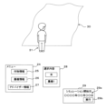
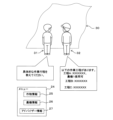
- the control unit 11 displays a virtual space on the display unit 14, and displays in the virtual space a farmland object 30 representing the farmland 1, an avatar 31 representing the user, and a menu screen 24.
- the virtual space is realized, for example, by VR or AR.
- the farmland object 30 reflects information in the farmland table T, for example, the area of the farmland. If the farmland table T includes the shape of the farmland, the shape of the farmland may be reflected in the farmland object 30.
- the farmland object 30 corresponds to the actual farmland.
- Image data representing the virtual space, the farmland object 30, the avatar 31, and the menu screen 24 are generated by the control program of the server 1 or the application program of the terminal 10.
- the image data is transmitted to the terminal 10.
- the control unit 11 displays the virtual space, the farmland object 30, the avatar 31, and the menu screen 24 on the display unit 14 based on the generated image data.
- multiple avatar 31 candidates may be displayed on the display unit 14, and the user may select one of the avatars 31, and the selected avatar 31 may be displayed on the display unit 14.
- the menu includes a crop information button 25, an agricultural machinery information button 26, and an advisor information button 27.
- FIG. 8A is an example of a screen displayed on the display unit 14 when the crop information button 25 is operated.
- crop buttons 25a to 25d indicating rice, tomato, eggplant, cucumber, etc.
- a back button 24e are displayed on the display unit 14.
- the user can operate the crop buttons 25a to 25d indicating the crops they wish to grow.
- the display screen of FIG. 7 is returned to.
- Image data indicating the crop buttons 25a to 25d and the back button 24e is generated by the control program of the server 1 or the application program of the terminal 10.
- the image data is generated by the control program of the server 1, the image data is transmitted to the terminal 10.
- the control unit 11 causes the display unit 14 to display the crop buttons 25a to 25d and the back button 24e based on the generated image data.
- FIG. 8B is an example of a screen displayed on the display unit 14 when the agricultural machinery information button 26 is operated.
- agricultural machinery buttons 26a to 26c indicating agricultural machinery 1, agricultural machinery 2, and agricultural machinery 3, and a back button 26d are displayed.
- a thumbnail indicating agricultural machinery 1 is displayed next to the agricultural machinery button 26a of agricultural machinery 1
- a thumbnail indicating agricultural machinery 2 is displayed next to the agricultural machinery button 26b of agricultural machinery 2
- a thumbnail indicating agricultural machinery 3 is displayed next to the agricultural machinery button 26c of agricultural machinery 3.
- the user can operate the agricultural machinery buttons 26a to 26c indicating the agricultural machinery he or she wishes to use. Only agricultural machinery that is available at the time when the agricultural machinery information button 26 is operated is displayed on the display unit 14.
- agricultural machinery that is unavailable at the time when the agricultural machinery information button 26 is operated may be displayed on the display unit 14.
- the unavailable agricultural machinery is displayed in a manner that is distinguishable from the available agricultural machinery, such as by being displayed in a different color from the available agricultural machinery, and the button for the unavailable agricultural machinery is configured not to be operable.
- the display screen of FIG. 7 is returned to.
- Image data showing each of the agricultural machine buttons 26a-26c and the back button 26d is generated by the control program of the server 1 or the application program of the terminal 10.
- image data is generated by the control program of the server 1, the image data is transmitted to the terminal 10.
- the control unit 11 causes each of the agricultural machine buttons 26a-26c and the back button 26d to be displayed on the display unit 14 based on the generated image data.
- the server 1 stores information about each agricultural machine, such as actual parameters of the agricultural machine 1, such as the running speed, the torque supplied to the working device, and the running direction, in the auxiliary storage unit 4, and updates it as necessary.
- FIG. 8C is an example of a screen displayed on the display unit 14 when the advisor information button 27 is operated.
- advisor buttons 27a to 27c showing the advisors A, B, and C, and a back button 27d are displayed.
- the advisor buttons 27a to 27c display a description of the advisor.
- the advisor's occupation and area of expertise are displayed. Examples of the advisor's occupation include farmer or agricultural machinery engineer. Examples of the advisor's area of expertise include the types of crops that have been grown in the past and the types of agricultural machinery that have been handled (tractors, rice transplanters, combines, etc.).
- the advisor may be the owner of the farmland or a person other than the owner.
- the user can call the advisor by operating the advisor button 27a to 27c showing the advisor for whom advice is desired.
- the display screen of FIG. 7 is displayed again.
- the advisor corresponds to a person involved in agricultural work or a person involved in agricultural machinery.
- Image data representing each of the advisor buttons 27a-27c and the back button 27d is generated by the control program of the server 1 or the application program of the terminal 10.
- image data is generated by the control program of the server 1, the image data is sent to the terminal 10.
- the control unit 11 causes each of the advisor buttons 27a-27c and the back button 27d to be displayed on the display unit 14 based on the generated image data.
- the advisor has a terminal 10.
- An application program for agricultural support is installed, i.e., stored, in the terminal 10.
- a call command is sent from the user's terminal 10 to the advisor's terminal 10.
- the call command may be sent directly from the user's terminal 10 to the advisor's terminal 10 or may be sent via the server 1.
- the application program installed in the advisor's terminal 10 receives a call command, it displays information indicating that the advisor is being called and a receive button on the display unit 14 of the advisor's terminal 10. If the advisor's terminal 10 has a speaker or vibration function, it may emit a sound from the speaker or vibrate the terminal 10.
- two-way communication between the advisor's terminal 10 and the user's terminal 10 is established. If two-way communication is not established, a message indicating that communication cannot be established is displayed on the display unit 14, and the display screen of FIG. 7 is displayed again. If the two-way communication is terminated, the display screen of FIG. 7 is displayed again.
- FIG. 9 is an example of a screen displayed on the display unit 14 when the crop button 25a indicating rice is operated and the agricultural machinery button 26a indicating the agricultural machinery 1 is operated.
- the crop button 25a indicating rice When rice is selected as the crop to be grown by operating the crop button 25a indicating rice, and when the agricultural machinery button 26a indicating the agricultural machinery 1 is selected as the agricultural machinery to be used by operating the agricultural machinery button 26a indicating the agricultural machinery 1, a display field 28 indicating the selection is displayed on the display unit 14, and rice and the agricultural machinery 1 are displayed inside the display field 28.
- a display field 29 indicating the simulation start date is displayed on the display unit 14. In the display field 29 indicating the simulation start date, a field 29a for inputting the date and an execute button 29b are displayed.
- Image data indicating the display field 28 indicating the selection, the display field 29 indicating the simulation start date, the field 29a for inputting the date, and the execute button 29b are generated by the control program of the server 1 or the application program of the terminal 10.
- the control unit 11 causes the display unit 14 to display a display field 28 indicating the selected content, a display field 29 indicating the simulation start date, a field 29a for inputting the date, and an execute button 29b.
- the user's terminal 10 transmits the selected content, i.e., the rice and agricultural machine 1, and the desired work start date, to the server 1.
- Server 1 receives the selected content and the desired start date of work, and simulates the rice growing process on farmland 1 over time based on the selected content, the desired start date of work, and the information in farmland table T.
- Server 1 generates image data showing the growth state of the rice on a specified date. For example, it generates image data showing the growth state of the rice every week.
- FIGS. 10A to 10C are examples of images showing the rice growing process displayed on the display unit 14 of the terminal 10.
- the server 1 transmits each generated image data to the user's terminal 10.
- the control unit 11 of the terminal 10 causes a crop object 30a showing a crop to be displayed on a farmland object 30 showing the farmland 1 based on each received image data.
- FIG. 10A an image showing rice seedlings is displayed on the display unit 14 together with the date
- FIG. 10B an image showing grown rice leaves is displayed on the display unit 14 together with the date
- FIG. 10C an image showing ears of rice is displayed on the display unit 14 together with the date.
- the server 1 acquires the percentages of sunny, cloudy and rainy days, the average temperature, the average humidity, etc. stored in the weather column for the first period and the weather column for the second period in the farmland table T, and calculates the growth condition of the rice based on the percentages of sunny, cloudy and rainy days, the average temperature, the average humidity, etc. For example, if the desired work start date is included in the first period, the growth condition of the rice is calculated based on the percentages of sunny, cloudy and rainy days, the average temperature, the average humidity, etc.
- the growth condition of the rice is calculated based on the percentages of sunny, cloudy and rainy days, the average temperature, the average humidity, etc. in the second period.
- the percentages of sunny, cloudy and rainy days, the average temperature, the average humidity, etc. correspond to environmental information related to the environment, including the weather.
- the server 1 changes the crop object 30a representing rice (rice) in response to changes in the environment.
- the server 1 transmits image data representing the changed crop object 30a to the user's terminal 10.
- the control unit 11 of the terminal 10 displays the changed crop object 30a on the display unit 14 based on image data showing the changed crop object 30a. That is, the crop object 30a changes in the virtual space in response to changes in the environment.
- the server 1 acquires the yield map and fertilization map, and calculates the growth of rice in each section of the farmland object 30 of the farmland 1 based on the yield map and fertilization map. For example, since there is a correlation between the amount of fertilization and the amount of yield, the crop object 30a is changed in sections with a large amount of fertilization to speed up the growth of rice or increase the number of seeds in the ear, and the crop object 30a is changed in sections with a small amount of fertilization to slow down the growth of rice or decrease the number of seeds in the ear.
- the server 1 transmits image data showing the changed crop object 30a to the user's terminal 10.
- the control unit 11 of the terminal 10 displays the changed crop object 30a on the display unit 14 based on the image data showing the changed crop object 30a.
- the yield map and fertilization map correspond to production information. That is, the crop object 30a changes in the virtual space based on the production information.
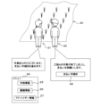
- FIG. 11 is an example of an image showing an agricultural machinery object 40 and a farmland object 30 operating in a virtual space.
- FIG. 11 is an image viewed from above.
- the server 1 For example, if the agricultural machinery 1 is a rice transplanter, the server 1 generates an agricultural machinery object 40 representing the rice transplanter.
- the server 1 calculates the operation of the agricultural machinery object 40 relative to the farmland object 30 based on the travel data, and generates image data showing the moving agricultural machinery object 40 based on the calculated operation.
- the image data also includes video data, which is a collection of temporally continuous still images.
- the server 1 calculates the position of the crop object 30a, i.e., the seedling, to be planted in the farmland object 30 in association with the operation of the agricultural machinery object 40, i.e., the rice transplanter, and generates image data of the seedling to be displayed at the calculated position.
- the server 1 stores the image data showing the moving agricultural machinery object 40 and the image data showing the crop object 30a in association with each other in the auxiliary memory unit 4 or the main memory unit 3.
- the server 1 transmits the associated image data showing the moving agricultural machinery object and the image data showing the crop object 30a to the user's terminal 10.
- the control unit 11 of the terminal 10 receives the image data showing the moving agricultural machinery object 40 and the image data showing the crop object 30a
- the control unit 11 displays an image showing the agricultural machinery object 40 and an image showing the crop object 30a on the display unit 14 based on the image data showing the moving agricultural machinery object 40 and the image data showing the crop object 30a. That is, the agricultural machinery object 40 and the crop object 30a are displayed in the virtual space, and the operation of the agricultural machinery object 40 relative to the farmland object 30 is executed in the virtual space.
- the crop object 30a (seedling) appears on the farmland object 30 according to the movement of the farmland object 30. That is, the farmland object 30 and the crop object 30a change in the virtual space according to the operation of the agricultural machinery object 40.
- FIG. 11 shows an image viewed from above, but an image viewed from an oblique direction may be displayed on the display unit 14.
- the agricultural machinery object 40 represents a combine harvester
- the movement of the agricultural machinery object 40 causes the crop object 30a, which represents rice, to be harvested.
- the farmland object 30 and the crop object 30a change in the virtual space in response to the movement of the agricultural machinery object 40.
- the server 1 simulates the rice growing process in the farmland 1 over time based on the content selected by the user, the desired date of work start, and the information in the farmland table T.
- the terminal 10 may also simulate the rice growing process in the farmland 1 over time based on the content selected by the user, the desired date of work start, and the information in the farmland table T.
- the terminal 10 When the terminal 10 performs the simulation, the terminal 10 generates each image data showing the rice growing state, acquires the percentage of sunny, cloudy, and rainy days, average temperature, average humidity, etc.
- the terminal 10 changes the crop object 30a showing rice (rice) in response to changes in the environment, and displays the changed crop object 30a on the display unit 14 based on the image data showing the changed crop object 30a.
- FIG. 12 is an example of an image displayed on the display unit 14 when the simulation is completed.
- the control unit 11 of the user's terminal 10 causes the display unit 14 to display an operation history button 45 and a request button 46.
- the server 1 stores the parameters of the agricultural machinery object 40 operated by the simulation, such as the running speed, the torque supplied to the work device, and the running direction, in chronological order in the auxiliary memory unit 4 or the main memory unit 3.
- the user's terminal 10 acquires the parameters of the agricultural machinery object 40 from the server 1.
- the terminal 10 displays the parameters (not shown) in chronological order on the display unit 14, and also displays a back button (not shown). The user can check the parameters of the agricultural machinery object 40 and check for any abnormalities.
- the back button is operated, the display screen of FIG. 12 is displayed again.
- Image data showing the operation history button 45 and the request button 46 is generated by the control program of the server 1 or the application program of the terminal 10.
- the image data is transmitted to the terminal 10.
- the control unit 11 causes the display unit 14 to display the operation history button 45 and the request button 46 based on the generated image data.
- the terminal 10 may store parameters of the agricultural machinery object 40 operated by the simulation, such as the running speed, the torque supplied to the work device, and the running direction, in chronological order in the auxiliary memory unit 13 or the main memory unit 12.
- the user's terminal 10 displays the stored agricultural machinery object 40 on the display unit 14, and also displays a back button (not shown).
- FIG. 13 is an example of a screen displayed on the display unit 14 when the request button 46 is operated.
- the farmland object 30 corresponds to the actual farmland.
- the request button 46 is a button for asking another person to perform the work shown in the simulation on the actual farmland corresponding to the farmland object 30.
- the auxiliary memory unit 4 of the server 1 prestores a person who will perform the work on the actual farmland (hereinafter, a proxy). Note that the user may perform the work on the farmland themselves without requesting a proxy.
- a process button 46a indicating process A and agricultural machine 1 are displayed on the display unit 14.
- process A is rice planting
- process B is weeding
- process C is harvesting
- agricultural machine 1 is a rice transplanter.
- Process A and agricultural machine 1 are displayed together to indicate that agricultural machine 1 is used to perform process A.
- agricultural machine 1 is displayed together with process A. If the user has not selected agricultural machine 1 before starting the simulation, agricultural machine 1 is not displayed.
- Image data indicating each process button 46a to 46c is generated by the control program of the server 1 or the application program of the terminal 10.
- the image data is transmitted to the terminal 10.
- the control unit 11 causes each process button 46a to 46c to be displayed on the display unit 14 based on the generated image data.
- FIG. 14 is an example of a screen displayed on the display unit 14 when the process button indicating process A and agricultural machine 1 is operated.
- the request button 46 for example, as shown in FIG. 14, the content of the operated process button (process A and agricultural machine 1), the cost, the request confirmation button 47a, and the cancel button 47b are displayed.
- the user checks the cost and operates the request confirmation button or the cancel button.
- the display screen of FIG. 12 is returned to.
- Image data indicating the content of the operated process button, the cost, the request confirmation button 47a, and the cancel button 47b are generated by the control program of the server 1 or the application program of the terminal 10.
- the image data is generated by the control program of the server 1, the image data is transmitted to the terminal 10.
- the control unit 11 causes the display unit 14 to display the content of the operated process button, the cost, the request confirmation button 47a, and the cancel button 47b based on the generated image data.
- the control unit 2 of the server 1 notifies the agent that a request has been made.
- the agent has a terminal 10 on which an application program is installed.
- the agent operates the terminal 10 and transmits information to the server 1 indicating that the request has been accepted, the server 1 notifies the user's terminal 10 that the request has been confirmed.
- the control unit 11 of the user's terminal 10 receives the notification, it causes the display unit 14 to display, for example, as shown in FIG. 15, an acceptance screen indicating that the request has been accepted and that the user will be contacted when the work is completed, and a back button 47c.
- Image data indicating that the request has been accepted, that the user will be contacted when the work is completed, and the back button 47c are generated by the control program of the server 1 or the application program of the terminal 10.
- the control unit 11 Based on the generated image data, the control unit 11 causes the display unit 14 to display that the request has been accepted, that a notification will be sent when the work is completed, and a back button 47c.
- FIG. 16 is an example of a screen displayed on the display unit 14 when the agent completes the work.
- the agent completes the work (rice planting) on the actual farmland 1
- the agent inputs information indicating that the work has been completed into the agent's terminal 10.
- the server 1 transmits the received information and data indicating the farmland object 30 after the work has been completed to the user's terminal 10.
- the control unit 11 of the user's terminal 10 receives the information and the data indicating the farmland object 30, it causes a receive button (not shown) to be displayed on the display unit 14.
- the receive button for example, as shown in FIG.
- the control unit 11 of the user's terminal 10 causes the display unit 14 to display the farmland object 30, the user's avatar 31, a payment procedure button 48, and a message requesting completion of the work and payment.
- the farmland object 30 changes compared to its state at the time of the work request. For example, if the requested work is rice planting and the state at the time of the work request is a state in which no seedlings have been planted, the farmland object 30 changes to a state after the seedlings have been planted.
- Image data showing the farmland object 30, the avatar 31, the payment procedure button 48, and a message requesting completion of the work and payment is generated by the control program of the server 1 or the application program of the terminal 10.
- the image data is generated by the control program of the server 1, the image data is transmitted to the terminal 10.
- the control unit 11 Based on the generated image data, the control unit 11 causes the display unit 14 to display the farmland object 30, the avatar 31, the payment procedure button 48, and a message requesting completion of the work and payment.
- the agent may also input a photograph (image data) showing the farmland 1 after the work has been completed into his own terminal 10.
- the agent's terminal 10 is equipped with an imaging unit, such as a camera, which captures an image of the farmland 1.
- the terminal 10 transmits the information and the photograph to the server 1.
- the server 1 transmits the received information and the photograph to the user's terminal 10.
- the control unit 11 of the user's terminal 10 receives the information and the photograph, and when the receive button is operated, causes the photograph to be displayed on the display unit 14 together with the farmland object 30 or in place of the farmland object 30.
- the user's terminal 10 sends an instruction to start the billing process to the server 1.
- the payment procedure button 48 functions as a reception unit that accepts payment of fees.
- the server 1 receives the instruction to start the billing process, it executes the billing process for the use of the agricultural machine 1 and the work of process A. Specifically, it executes the billing process to the credit card company or the withdrawal process from the user's bank account for the amount shown in FIG. 14. Information required for the billing process, such as the user's credit card number and bank account, is stored in advance in the server 1.
- the control unit 11 of the user's terminal 10 may display a screen on the display unit 14 for inputting information required for the billing process.
- the input information required for the billing process is sent to the server 1, and the server 1 executes the billing process.
- the server 1 sends information indicating the completion of the billing to the user's terminal 10.
- the control unit 11 of the terminal 10 displays information indicating the completion of the billing (not shown) on the display unit 14.
- an exit button (not shown) is always displayed on the display unit 14. If the user operates the exit button, execution of the application program is forcibly terminated. The forced termination is executed as an interrupt process.
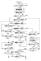
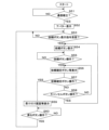
- FIGS 17 and 18 are flowcharts explaining the display process for displaying a virtual space on the display unit 14 of the user's terminal 10.
- the control unit 11 of the user's terminal 10 determines whether or not an application program has started (S1). If the application program has not started (S1: NO), the control unit 11 returns the process to step S1. If the application program has started (S1: YES), the control unit 11 obtains information from the farmland table T, i.e., information indicating the farmland that is a candidate for loan (S2).
- the control unit 11 causes the display unit 14 to display the farmland button (S3, see FIG. 6), and determines whether the farmland button has been operated (S4). If it is determined that the farmland button has not been operated (S4: NO), the control unit 11 returns the process to step S4. If it is determined that the farmland button has not been operated (S4: YES), the control unit 11 causes the display unit 14 to display the farmland object 30, the avatar 31 representing the user, and the menu screen 24 (S5, see FIG. 7).
- the control unit 11 determines whether the crop information button 25 has been operated (S6). If it is determined that the crop information button 25 has not been operated (S6: NO), the control unit 11 determines whether the agricultural machinery information button 26 has been operated (S7). If it is determined that the agricultural machinery information button 26 has not been operated (S7: NO), the control unit 11 determines whether the advisor information button 27 has been operated (S11). If it is determined that the advisor information button 27 has not been operated (S11: NO), the control unit 11 returns the process to step S5.
- step S6 If it is determined in step S6 that the crop information button 25 has been operated (S6: YES), the control unit 11 causes the display unit 14 to display each of the crop buttons 25a to 25d and the back button 25e (S17, see FIG. 8A), and determines whether or not the back button 25e has been operated (S18). If it is determined that the back button 25e has been operated (S18: YES), the control unit 11 returns the process to step S6. If it is determined that the back button 25e has not been operated (S18: NO), the control unit 11 determines whether or not the crop buttons 25a to 25d have been operated (S19). If it is determined that the crop buttons 25a to 25d have not been operated (S19: NO), the control unit 11 returns the process to step S17.
- the control unit 11 displays the selection, i.e., the selected crop, on the display unit 14 (S20, see FIG. 9).
- step S7 If it is determined in step S7 that the agricultural machinery information button 26 has been operated (S7: YES), the control unit 11 causes the display unit 14 to display each of the agricultural machinery buttons 26a to 26c and the back button 26d (S8, see FIG. 8B), and determines whether or not the back button 26d has been operated (S9). If it is determined that the back button 26d has been operated (S9: YES), the control unit 11 returns the process to step S6. If it is determined that the back button 26d has not been operated (S9: NO), the control unit 11 determines whether or not the agricultural machinery buttons 26a to 26c have been operated (S10).
- control unit 11 If it is determined that the agricultural machinery buttons 26a to 26c have not been operated (S10: NO), the control unit 11 returns the process to step S8. If it is determined that the agricultural machinery buttons 26a to 26c have been operated (S10: YES), i.e., if the user has selected the agricultural machinery they wish to use, the control unit 11 displays the selection, i.e., the selected agricultural machinery, on the display unit 14 (S20, see FIG. 9).
- step S11 If it is determined in step S11 that the advisor information button 27 has been operated (S11: YES), the control unit 11 causes the display unit 14 to display each of the advisor buttons 27a to 27c and the back button 27d (S12), and determines whether or not the back button 27d has been operated (S13). If it is determined that the back button 27d has been operated (S13: YES), the control unit 11 returns the process to step S6. If it is determined that the back button 27d has not been operated (S13: NO), the control unit 11 determines whether or not the advisor buttons 27a to 27c have been operated (S14). If it is determined that the advisor buttons 27a to 27c have not been operated (S14: NO), the control unit 11 returns the process to step S12.
- the control unit 11 determines whether or not two-way communication has been established between the advisor's terminal 10 and the user's terminal 10 (S15). If it is determined that two-way communication has not been established (S15: NO), the control unit 11 displays on the display unit 14 a message indicating that two-way communication cannot be established, and returns to step S6. If it is determined that two-way communication has been established (S15: YES), the control unit 11 determines whether or not two-way communication has ended (S16). If it is determined that two-way communication has not ended (S16: NO), the control unit 11 returns to step S16. If it is determined that two-way communication has ended (S16: YES), the control unit 11 returns to step S6.
- step S20 after displaying the selected content on the display unit 14, the control unit 11 determines whether or not the execute button 29b has been operated (S21, see FIG. 9). If the execute button 29b has not been operated (S21: NO), or if the crop information button 25, agricultural machinery information button 26, or advisor information button 27 has not been operated, the control unit 11 returns the process to step S20 (see FIG. 9). Note that in step S21, if the execute button 29b has not been operated but the crop information button 25, agricultural machinery information button 26, or advisor information button 27 has been operated, the control unit 11 performs the same process as steps S17 to S19, S8 to S10, or S12 to S16.
- step S20 if the back button 25e, 26d, or 27d is operated (S18: YES, S9: YES, S13: YES), two-way communication is not established (S15: NO), or two-way communication ends (S16: YES), the control unit 11 returns the process to step S20 instead of step S6 (see FIG. 7).
- step S21 If it is determined in step S21 that the execute button 29b has been operated (S21: YES), the control unit 11 causes the farm machine object 40 and the crop object 30a to be displayed on the farmland object 30, and the server 1 executes a simulation showing the growth process of the crops (S22, see Figures 10A to 10C and 11). Note that the terminal 10 may execute the simulation process instead of the server 1.
- the control unit 11 causes the display unit 14 to display the operation history button 45 and the request button 46 (S23), and determines whether or not the operation history button 45 has been operated (S24). If it is determined that the operation history button 45 has been operated (S24: YES), the control unit 11 causes the display unit 14 to display parameters (not shown) (S31), and determines whether or not the back button (not shown) has been operated (S32). If it is determined that the back button has not been operated (S32: NO), the control unit 11 returns the process to step S31. If it is determined that the back button has been operated (S32: YES), the control unit 11 returns the process to step S23.
- step S24 determines whether or not the request button 46 has been operated (S25). If it is determined that the request button 46 has not been operated (S25: NO), the control unit 11 returns the process to step S23. If it is determined that the request button 46 has been operated (S25: YES), the control unit 11 displays the process button on the display unit 14 (S26, see FIG. 13), and determines whether or not the process button has been operated (S27). If it is determined that the process button has not been operated (S27: NO), the control unit 11 returns the process to step S27.
- step S27 If it is determined in step S27 that the process button has been operated (S27: YES), the control unit 11 displays the content of the operated process button, the cost, the request confirmation button, and the cancel button on the display unit 14 (S28, see FIG. 14), and determines whether or not the request confirmation button has been operated (S29).
- control unit 11 determines whether or not the cancel button has been operated (S30). If it is determined that the cancel button has not been operated (S30: NO), the control unit 11 returns the process to step S28. If it is determined in step S30 that the cancel button has been operated (S30: YES), the control unit 11 returns the process to step S23.
- step S29 If it is determined in step S29 that the request confirmation button has been operated (S29: YES), the control unit 11 determines whether or not a notification that the request has been confirmed has been received (S33). If it is determined that a notification that the request has been confirmed has not been received (S33: NO), the control unit 11 returns the process to step S33. If it is determined in step S33 that a notification that the request has been confirmed has been received (S33: YES), the control unit 11 displays the reception screen and the back button 47c on the display unit 14 (S34). The control unit 11 determines whether or not the back button 47c has been operated (S35). If it is determined that the back button 47c has not been operated (S35: NO), the control unit 11 returns the process to step S35. If it is determined in step S35 that the back button 47c has been operated (S35: YES), the control unit 11 returns the process to step S23.
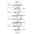
- FIG. 19 is a flowchart explaining the billing process that is executed when the work by the agent is completed.
- the control unit 11 determines whether or not information indicating that the work by the agent is completed and the farmland object 30 after the work is completed have been received (S41). If it is determined that the information and the farmland object 30 have not been received (S41: NO), the control unit 11 returns the process to step S41. If it is determined in step S41 that the information and the farmland object have been received (S41: YES), the control unit 11 displays a receive button (not shown) on the display unit 14 (S42) and determines whether or not the receive button has been operated (S43). If it is determined that the receive button has not been operated (S43: NO), the control unit 11 returns the process to step S42.
- a receive button not shown
- step S43 If it is determined in step S43 that the receive button has been operated (S43: YES), the control unit 11 causes the display unit 14 to display the farmland object, the user's avatar 31, the payment procedure button 48, and a message requesting completion of the work and payment (S44, see FIG. 16).
- the control unit 11 determines whether the payment procedure button 48 has been operated (S45). If it is determined that the payment procedure button 48 has not been operated (S45: NO), the control unit 11 returns the process to step S45. If it is determined that the payment procedure button 48 has been operated (S45: YES), the control unit 11 sends a charge process start instruction to the server 1 (S46) and determines whether information indicating charge completion has been received from the server 1 (S47). If it is determined that information indicating charge completion has not been received (S47: NO), the control unit 11 returns the process to step S47.
- control unit 11 causes the display unit 14 to display information indicating that billing has been completed (not shown) (S48), and ends the process.
- a farmland object 30 is displayed in a virtual space.
- the farmland object 30 corresponds to farmland, for example farmland 1 rented by a user. Before actually working on farmland 1, the user can check each step of the farm work on the farmland object 30.
- a farm machinery object 40 is displayed in the virtual space.
- the user inputs operations for the farm machinery object 40.
- the farm machinery object 40 operates on the farmland object 30, and the farmland object 30 changes in response to the operation of the farm machinery object 40.
- the crop object 30a is also displayed on the farmland object 30.
- the user inputs operations for the farm machinery object 40.
- the farm machinery object 40 operates on the farmland object 30, and the crop object 30a changes in response to the operation of the farm machinery object 40.
- the operation history of the agricultural machinery object 40 can also be output.
- the user can check the operation history and change the settings of the agricultural machinery.
- the crop object 30a changes in the virtual space in response to changes in the environment, including the weather, allowing the user to understand the crop growth process that reflects the changes in the environment.
- the crop object 30a is changed in virtual space based on production information, including fertilization or crop yield, so the user can understand the crop growth process that reflects the production information.
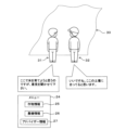
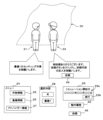
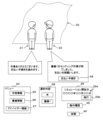
- Figures 20 and 21 are examples of screens that are displayed when the user operates the button 21 for farmland 1 to call up the advisor, Mr. A.
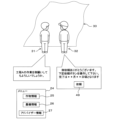
- the control unit 11 of the user's terminal 10 causes the farm object 30 indicating farmland 1 and the user's avatar 31 to be displayed on the display unit 14, i.e., in the virtual space.
- the control unit 11 of the user's terminal 10 establishes two-way communication with Mr. A's terminal 10 and causes an avatar 32 indicating Mr. A to be displayed in the virtual space.
- the user's avatar 31 and Person A's avatar 32 appear facing the farmland object 30 in the virtual space.
- the user's avatar 31 and Person A's avatar 32 can communicate with each other, for example, by sending messages to each other. Voice, image or video may also be sent to each other.
- the user can send questions to Person A, and Person A can answer the questions.
- Image data showing the farmland object 30, each avatar 31, 32, and the menu screen 24 is generated by the control program of the server 1 or the application program of the terminal 10.
- image data is generated by the control program of the server 1
- the image data is transmitted to the terminal 10.
- the control unit 11 causes the display unit 14 to display the farmland object 30, each avatar 31, 32, and the menu screen 24 based on the generated image data.
- a request button display command is sent from the advisor's terminal 10 to the server 1, along with information indicating process A and the agricultural machine 1, and the cost of the work on process A using the agricultural machine 1, via the server 1 to the user's terminal 10.
- the control unit 11 of the user's terminal 10 receives the request button display command, it causes the display unit 14 to display the request button 49.
- Image data indicating the request button 49 is generated by the control program of the server 1 or an application program of the terminal 10.
- the control unit 11 causes the display unit 14 to display the request button 49 based on the generated image data.
- a screen similar to that shown in FIG. 14 is displayed on the display unit 14.
- the user checks the cost and operates the request confirmation button a screen similar to that shown in FIG. 15 is displayed on the display unit 14, and the request to the advisor is confirmed.
- the advisor performs the requested work on the actual farmland 1.
- FIG. 23 is an example of a screen displayed on the display unit 14 when the work by the advisor is completed.
- the advisor completes the work on the actual farmland 1 (e.g., rice planting)
- the advisor inputs information indicating that the work is completed into the advisor's terminal 10.
- the server 1 transmits the received information and data indicating the farmland object 30 after the work is completed to the user's terminal 10.
- the control unit 11 of the user's terminal 10 receives the information and the data indicating the farmland object 30, it displays a receive button (not shown) on the display unit 14.
- the receive button for example, as shown in FIG.
- the control unit 11 of the user's terminal 10 displays the farmland object 30, the user's avatar 31, a payment procedure button 48, and a message requesting completion of the work and payment on the display unit 14.
- the farmland object 30 changes compared to its state at the time of the work request. For example, if the requested work is rice planting and the state at the time of the work request is one in which no seedlings have been planted, the farmland object 30 changes to a state after the seedlings have been planted.
- Image data showing the payment procedure button 48 and a message requesting completion of the work and payment is generated by the control program of the server 1 or an application program of the terminal 10. When the image data is generated by the control program of the server 1, the image data is transmitted to the terminal 10. Based on the generated image data, the control unit 11 causes the display unit 14 to display the payment procedure button 48 and a message requesting completion of the work and payment.
- the advisor may also input a photograph (image data) showing the farmland 1 after the work has been completed into his own terminal 10.
- the advisor's terminal 10 is equipped with an imaging unit, such as a camera, which captures an image of the farmland 1.
- the terminal 10 transmits the information and the photograph to the server 1.
- the server 1 transmits the received information and the photograph to the user's terminal 10.
- the control unit 11 of the user's terminal 10 receives the information and the photograph, and when the receive button is operated, causes the photograph to be displayed on the display unit 14 together with the farmland object 30 or in place of the farmland object 30.
- the user can input a message, such as a message of thanks for the work, into his/her terminal 10.
- the user's terminal 10 sends an instruction to start the billing process to the server 1.
- the payment procedure button 48 functions as a reception unit that accepts payment of the fee.
- the server 1 executes the billing process for the use of the agricultural machine 1 and the work of process A. Specifically, the amount shown in FIG. 14 is billed to the credit card company or debited from the user's bank account. Information necessary for the billing process, such as the user's credit card number and bank account, is stored in advance in the server 1.
- the control unit 11 of the user's terminal 10 may display a screen on the display unit 14 for inputting information necessary for the billing process.
- the input information necessary for the billing process is sent to the server 1, and the server 1 executes the billing process.
- the server 1 sends information indicating the completion of the billing process to the user's terminal 10.
- the control unit 11 of the terminal 10 displays information indicating the completion of the billing process (not shown) on the display unit 14.
- FIG. 24 is a flowchart explaining the display process for displaying a virtual space on the display unit 14 of the user's terminal 10.
- the farmland object 30 of farmland 1 and the user's avatar 31 are already displayed on the display unit 14 of the user's terminal 10, and the user has operated the advisor button 27a representing Mr. A.
- the control unit 11 of the user's terminal 10 determines whether or not two-way communication has been established between the advisor's terminal 10 and the user's terminal 10 (S51). If it is determined that two-way communication has not been established (S51: NO), the control unit 11 returns the process to step S51. Note that if two-way communication has not been established even after a predetermined period of time has elapsed since the start of the communication establishment process, the control unit 11 may end the communication establishment process and return to the screen shown in FIG. 7.
- control unit 11 causes the display unit 14 to display the advisor's avatar 32 (S52).
- the user and advisor A can now communicate in the virtual space via the avatars 31 and 32. For example, they can send messages to each other.
- the control unit 11 determines whether or not a request button display command has been received from the advisor's terminal 10 (S53). If it determines that a request button display command has not been received from the advisor's terminal 10 (S53: NO), the control unit 11 returns the process to step S53. If it determines that a request button display command has been received from the advisor's terminal 10 (S53: YES), the control unit 11 causes the display unit 14 to display the request button 49 (S54), and determines whether or not the request button 49 has been operated (S55).
- control unit 11 If it is determined that the request button 49 has not been operated (S55: NO), the control unit 11 returns the process to step S55. If it is determined that the request button 49 has been operated (S55: YES), the control unit 11 causes the agricultural machine 1, process A, the cost, the request confirmation button, and the cancel button to be displayed on the display unit 14 (S56, see FIG. 14), and determines whether the request confirmation button has been operated (S57).
- control unit 11 determines whether or not the cancel button has been operated (S58). If it is determined that the cancel button has not been operated (S58: NO), the control unit 11 returns the process to step S56. If it is determined that the cancel button has been operated (S58: YES), the control unit 11 returns the process to step S54.
- step S57 If it is determined in step S57 that the request confirmation button has been operated (S57: YES), the control unit 11 causes the display unit 14 to display the reception screen and the back button 47c (S59). The control unit 11 determines whether or not the back button 47c has been operated (S60). If it is determined that the back button 47c has not been operated (S60: NO), the control unit 11 returns the process to step S60. If it is determined in step S60 that the back button 47c has been operated (S60: YES), the control unit 11 returns the process to step S53.
- the billing process is executed when the work by the advisor is completed.
- the billing process in the second embodiment is the same as the process in steps S41 to S48 of FIG. 19, except that the agent is replaced with the advisor, so a detailed description of this process is omitted.
- an avatar 32 of an advisor (a person involved in agricultural work) is displayed in a virtual space.
- the user can receive advice on work processes from, for example, an avatar 32 of a farmer.
- the user can also request that relevant parties in the farm work carry out work on the actual farmland 1.
- the farmland object 30 changes in the virtual space according to the work. This allows the user to intuitively understand that work has been carried out.
- Figure 25 is an example of a screen that is displayed when the user operates the button 21 for farmland 1 to call up advisor B.
- the control unit 11 of the user's terminal 10 causes the farmland object 30 indicating farmland 1 and the user's avatar 31 to be displayed on the display unit 14, i.e., in the virtual space.
- the control unit 11 of the user's terminal 10 establishes two-way communication with B's terminal 10 and causes an avatar 33 indicating B to be displayed in the virtual space.
- the user's avatar 31 and Person B's avatar 33 appear facing the farmland object 30 in the virtual space.
- the user's avatar 31 and Person B's avatar 33 are capable of communication, and can send messages to each other, for example. Voice, images, or video may also be sent to each other.
- the user can send questions to Person B, and Person B can answer the questions.
- Figure 26 is an example of a screen that is displayed when a user requests work from an advisor.
- the user sends a message to advisor B requesting that he set up agricultural machinery 1.
- the advisor can reply with a message.
- the advisor inputs information indicating the setting up of agricultural machinery 1 into terminal 10, and causes a request button 49 to be displayed on the display unit 14 of the user's terminal 10 along with the reply message.
- a request button display command is sent from the advisor's terminal 10 to server 1, information indicating the setting up of agricultural machinery 1, and the cost of the setting up of agricultural machinery 1 to be sent to the user's terminal 10 via server 1.
- the control unit 11 of the user's terminal 10 receives the request button display command, it causes the request button 49 to be displayed on the display unit 14.
- the request button 49 When the user operates the request button 49, the setting up of agricultural machinery 1, the cost, a request confirmation button, and a cancel button are displayed. That is, a screen in which the contents of the operated process button in FIG. 14 (Process A and Agricultural Machine 1) are replaced with the setting work of Agricultural Machine 1 is displayed on the display unit 14.
- a screen similar to that of FIG. 15 is displayed on the display unit 14, and the request to the advisor is confirmed.
- the advisor performs the requested work on the actual Agricultural Machine 1.
- Advisor B changes the settings of, for example, parameters of the actual Agricultural Machine 1, such as the running speed, the torque supplied to the work device, and the running direction. Advisor B inputs information about the changed settings into his own terminal 10 and sends it to the server 1.
- the server 1 overwrites and saves the changed parameters. That is, the parameters are updated.
- FIG. 27 is an example of a screen that is displayed on the display unit 14 when the advisor's work is completed.
- the advisor Mr. B
- the advisor inputs information indicating that the work is completed into the advisor's terminal 10.
- the server 1 transmits the received information and data indicating the farmland object 30 to the user's terminal 10.
- the control unit 11 of the user's terminal 10 receives the information and data indicating the farmland object 30, it displays a receive button (not shown) on the display unit 14.
- the control unit 11 of the user's terminal 10 displays the farmland object 30, the user's avatar 31, a payment procedure button 48, and a message requesting completion of the work and payment on the display unit 14.
- a display field 28 showing the selected content is displayed on the display unit 14, and rice and agricultural machinery 1 are displayed inside the display field 28.
- a display field 29 showing the simulation start date is displayed on the display unit 14 in the display field 29 showing the simulation start date.
- a field 29a for inputting the date and an execute button 29b are displayed.
- the user's terminal 10 transmits the selected content, i.e., the rice and agricultural machinery 1, and the desired work start date, to the server 1.
- the server 1 receives the selected content and the desired start date of work, and simulates the rice growing process on the farmland 1 over time based on the selected content, the desired start date of work, and the information in the farmland table T. For example, if the farm machinery 1 is a rice transplanter, the server 1 creates a farm machinery object 40 representing the rice transplanter, calculates the movement of the farm machinery object 40 relative to the farmland object 30 based on the changed parameters, and generates image data showing the farm machinery object 40 moving based on the calculated movement.
- the server 1 calculates the position of the crop object 30a, i.e., the seedling, to be planted in the farmland object 30 in association with the operation of the agricultural machinery object 40, i.e., the rice transplanter, and generates image data of the seedling to be displayed at the calculated position.
- the server 1 stores image data showing the moving agricultural machinery object 40 and image data showing the crop object 30a in association with each other in the auxiliary memory unit 4 or the main memory unit 3.
- the server 1 transmits the associated image data showing the moving agricultural machinery object 40 and image data showing the crop object 30a to the user's terminal 10.
- the control unit 11 of the user's terminal 10 receives the image data showing the moving agricultural machinery object 40 and the image data showing the crop object 30a, it displays the agricultural machinery object 40 and the crop object 30a in a virtual space, and executes the operation of the agricultural machinery object 40 relative to the farmland object 30 in the virtual space.
- the operation of the agricultural machinery object 40 is based on the changed parameters. In other words, the operation of the agricultural machinery object 40 is changed by changing the parameters (by the work of advisor B). For example, the movement path of the farmland object 30 is different before and after the parameter change.
- the user can input a message, such as a message of thanks for the work, into his/her terminal 10.
- the user's terminal 10 sends an instruction to start the billing process to the server 1.
- the payment procedure button 48 functions as a reception unit that accepts payment of the fee.
- the server 1 executes the billing process for the setting work of the agricultural machine 1. Specifically, the amount shown in FIG. 14 is billed to the credit card company or debited from the user's bank account. Information necessary for the billing process, such as the user's credit card number and bank account, is stored in advance in the server 1.
- the control unit 11 of the user's terminal 10 may display a screen on the display unit 14 for inputting information necessary for the billing process.
- the input information necessary for the billing process is sent to the server 1, and the server 1 executes the billing process.
- the server 1 sends information indicating the completion of the billing process to the user's terminal 10.
- the control unit 11 of the terminal 10 displays information indicating the completion of the billing process (not shown) on the display unit 14.
- a display process is executed to display a virtual space on the display unit 14 of the user's terminal 10.
- the billing process in the third embodiment is the same as the process in steps S51 to S60 of FIG. 24, except that advisor A is replaced with advisor B, and therefore a detailed description thereof is omitted.
- the billing process is executed when the work by the advisor is completed.
- the billing process in the third embodiment is the same as the process in steps S41 to S48 of FIG. 19, except that the agent is replaced with the advisor, so a detailed description of this process is omitted.
- an avatar 33 of an advisor is displayed in a virtual space.
- a user can receive advice on agricultural machinery settings from, for example, the avatar 33 of an agricultural machinery engineer.
- the user can request the avatar 33 of the person involved in the agricultural machinery to perform a task, such as setting up the agricultural machinery.
- a task such as setting up the agricultural machinery.
- the behavior of the agricultural machinery object 40 is changed in the virtual space according to the task. The user can intuitively understand the change in the behavior of the agricultural machinery after the settings are changed.
- the relevant person carry out the actual work on the agricultural machinery.
- the relevant person carries out the requested work, payment is made to the relevant person. Since the billing process is carried out by the application program of the terminal 10, the billing process can be carried out easily and reliably.
- the computer program can be deployed to be executed on a single computer, or on multiple computers located at one site or distributed across multiple sites and interconnected by a communications network N.
Landscapes
- Engineering & Computer Science (AREA)
- Business, Economics & Management (AREA)
- Life Sciences & Earth Sciences (AREA)
- Theoretical Computer Science (AREA)
- General Physics & Mathematics (AREA)
- Physics & Mathematics (AREA)
- Accounting & Taxation (AREA)
- General Engineering & Computer Science (AREA)
- Economics (AREA)
- Mechanical Engineering (AREA)
- Soil Sciences (AREA)
- Environmental Sciences (AREA)
- General Business, Economics & Management (AREA)
- Strategic Management (AREA)
- Marketing (AREA)
- Finance (AREA)
- Health & Medical Sciences (AREA)
- Marine Sciences & Fisheries (AREA)
- Tourism & Hospitality (AREA)
- Primary Health Care (AREA)
- Human Computer Interaction (AREA)
- Agronomy & Crop Science (AREA)
- Animal Husbandry (AREA)
- Development Economics (AREA)
- Mining & Mineral Resources (AREA)
- Human Resources & Organizations (AREA)
- General Health & Medical Sciences (AREA)
- Software Systems (AREA)
- Computer Hardware Design (AREA)
- Computer Graphics (AREA)
- Management, Administration, Business Operations System, And Electronic Commerce (AREA)
Abstract
Description
以下本発明を実施の形態1に係る農業支援システムを示す図面に基づいて説明する。図1は、農業支援システムを説明する説明図である。
作物データとは、農地に作付けした作物に関するデータであって、例えば、農地における作物の収量を示すデータ(収量データ)、作物の化学成分を示すデータ(作物成分データ)、作物の生育状況を示すデータ(生育データ)等である。作物成分データとは、例えば、作物の水分量(水分含有量)、作物の食味(タンパク含有量)等である。土壌データとは、農地の土壌に関するデータであって、例えば、土壌の化学成分を示すデータ(土壌成分データ)等である。
以下本発明を実施の形態2に係る農業支援システムを示す図面に基づいて説明する。実施の形態2に係る構成のうち、実施の形態1と同様な構成については同じ符号を付し、その詳細な説明を省略する。ユーザの端末10の制御部11は、農地のボタンを操作して、いずれかの農地を選択した場合、ユーザのアバター31と、選択した農地の農地オブジェクト30とを仮想空間に表示させる(図17、ステップS5参照)。またアドバイザー情報ボタン27を操作して、いずれかのアドバイザーを呼び出した場合、呼び出したアドバイザーのアバター32を仮想空間に表示させる。
以下本発明を実施の形態3に係る農業支援システムを示す図面に基づいて説明する。実施の形態3に係る構成のうち、実施の形態1又は2と同様な構成については同じ符号を付し、その詳細な説明を省略する。シミュレーションの実行によって、例えば農機1の移動経路が表示部14に示される(図11参照)。ユーザは、農機1の移動について、質問がある場合、アドバイザー情報ボタン27を操作して、農機に関する関係者、例えば農機1を扱った経験のあるエンジニア(アドバイザー)のBさんを呼び出すことができる。
2 制御部
3 主記憶部
4 補助記憶部
5、15 記録媒体
10 端末
11 制御部
12 主記憶部
13 補助記憶部
14 表示部
21~23 農地のボタン
25 作物情報ボタン
26 農機情報ボタン
27 アドバイザー情報ボタン
30 農地オブジェクト
31~33 アバター
40 農機オブジェクト
T 農地テーブル
Claims (15)
- 農地に関する農地情報を取得し、
取得した前記農地情報に基づいて、前記農地を示す農地オブジェクトを仮想空間に出力する
処理をコンピュータに実行させるコンピュータプログラム。 - 農機に関する農機情報を取得し、
取得した前記農機情報に基づいて、前記農機を示す農機オブジェクトを前記仮想空間に出力し、
前記農機オブジェクトに対する操作を受け付け、
受け付けた前記操作に基づき、前記農地オブジェクトに対する前記農機オブジェクトの動作を前記仮想空間にて実行し、
前記農機オブジェクトの動作に応じて、前記農地オブジェクトが前記仮想空間にて変化する
処理をコンピュータに実行させる請求項1に記載のコンピュータプログラム。 - 作物に関する作物情報を取得し、
前記作物情報に含まれる作物の選択を受け付け、
受け付けた前記作物を示す作物オブジェクトを前記農地オブジェクトに出力し、
受け付けた前記操作に基づき、前記作物オブジェクトに対する前記農機オブジェクトの動作を前記仮想空間にて実行し、
前記農機オブジェクトの動作に応じて、前記作物オブジェクトが前記仮想空間にて変化する
処理をコンピュータに実行させる請求項2に記載のコンピュータプログラム。 - 前記農機情報は、前記農地にて前記農機を使用する料金を含み、
前記農機オブジェクトの動作を実行した場合、前記料金の支払いを受け付ける
処理をコンピュータに実行させる請求項2又は3に記載のコンピュータプログラム。 - 前記農機オブジェクトの動作履歴を出力する
処理をコンピュータに実行させる請求項2又は3に記載のコンピュータプログラム。 - 作物に関する作物情報を取得し、
天候を含む環境に関する環境情報を取得し、
前記作物の選択を受け付け、
受け付けた前記作物を示す作物オブジェクトを前記農地オブジェクトに出力し、
前記環境の変化に応じて、前記受け付けた前記作物を示す作物オブジェクトが前記仮想空間にて変化する
処理をコンピュータに実行させる請求項1から3のいずれか一つに記載のコンピュータプログラム。 - 作物に関する作物情報と、施肥又は前記作物の収穫量を含む生産情報とを取得し、
前記作物情報に含まれる作物の選択を受け付け、
受け付けた前記作物を示す作物オブジェクトを前記農地オブジェクトに出力し、
前記生産情報に基づき、前記受け付けた作物を示す作物オブジェクトを前記仮想空間にて変化させる
処理をコンピュータに実行させる請求項1から3のいずれか一つに記載のコンピュータプログラム。 - 農作業に関する関係者のアバター情報を取得し、
前記関係者の呼出を受け付け、
取得した前記アバター情報に基づいて、呼び出した前記関係者のアバターを前記仮想空間に出力する
処理をコンピュータに実行させる請求項1から3のいずれか一つに記載のコンピュータプログラム。 - 前記仮想空間における前記関係者への作業の依頼を受け付け、
前記関係者が依頼された前記作業を実行した場合、前記作業に応じて、前記農地オブジェクトが前記仮想空間にて変化する
処理をコンピュータに実行させる請求項8に記載のコンピュータプログラム。 - 前記仮想空間における前記関係者への作業の依頼を受け付け、
前記関係者が依頼された前記作業を実行した場合、前記関係者への支払いを受け付ける
処理をコンピュータに実行させる請求項8に記載のコンピュータプログラム。 - 農機に関する農機関係者のアバター情報を取得し、
前記農機関係者の呼出を受け付け、
取得した前記アバター情報に基づいて、呼び出した前記農機関係者のアバターを前記仮想空間に出力する
処理をコンピュータに実行させる請求項2又は3に記載のコンピュータプログラム。 - 前記仮想空間における前記農機関係者への作業の依頼を受け付け、
前記農機関係者が依頼された前記作業を実行した場合、前記作業に応じて、前記農機オブジェクトの動作が前記仮想空間にて変更される
処理をコンピュータに実行させる請求項11に記載のコンピュータプログラム。 - 前記仮想空間における前記農機関係者への作業の依頼を受け付け、
前記農機関係者が依頼された前記作業を実行した場合、前記農機関係者への支払いを受け付ける
処理をコンピュータに実行させる請求項11に記載のコンピュータプログラム。 - 農地に関する農地情報を取得し、
取得した前記農地情報に基づいて、前記農地を示す農地オブジェクトを仮想空間に出力する
方法。 - 農地に関する農地情報を取得する取得部と、
取得した前記農地情報に基づいて、前記農地を示す農地オブジェクトを仮想空間に出力する出力部と
を備える装置。
Priority Applications (3)
| Application Number | Priority Date | Filing Date | Title |
|---|---|---|---|
| EP24832034.3A EP4738231A1 (en) | 2023-06-27 | 2024-06-27 | Computer program, method, and device |
| JP2025530190A JPWO2025005175A1 (ja) | 2023-06-27 | 2024-06-27 | |
| US19/401,648 US20260076286A1 (en) | 2023-06-27 | 2025-11-26 | Computer program, method, and apparatus |
Applications Claiming Priority (2)
| Application Number | Priority Date | Filing Date | Title |
|---|---|---|---|
| JP2023-105310 | 2023-06-27 | ||
| JP2023105310 | 2023-06-27 |
Related Child Applications (1)
| Application Number | Title | Priority Date | Filing Date |
|---|---|---|---|
| US19/401,648 Continuation US20260076286A1 (en) | 2023-06-27 | 2025-11-26 | Computer program, method, and apparatus |
Publications (1)
| Publication Number | Publication Date |
|---|---|
| WO2025005175A1 true WO2025005175A1 (ja) | 2025-01-02 |
Family
ID=93939179
Family Applications (1)
| Application Number | Title | Priority Date | Filing Date |
|---|---|---|---|
| PCT/JP2024/023307 Ceased WO2025005175A1 (ja) | 2023-06-27 | 2024-06-27 | コンピュータプログラム、方法及び装置 |
Country Status (4)
| Country | Link |
|---|---|
| US (1) | US20260076286A1 (ja) |
| EP (1) | EP4738231A1 (ja) |
| JP (1) | JPWO2025005175A1 (ja) |
| WO (1) | WO2025005175A1 (ja) |
Citations (5)
| Publication number | Priority date | Publication date | Assignee | Title |
|---|---|---|---|---|
| JP2002140387A (ja) * | 2000-10-31 | 2002-05-17 | Tadashi Kai | 実現象の擬似体験システム |
| JP2013111135A (ja) * | 2011-11-25 | 2013-06-10 | Telefarm Co Ltd | 農作物栽培連動システム |
| JP2017135994A (ja) * | 2016-02-01 | 2017-08-10 | 株式会社長寿乃里 | サーバ装置、作業依頼システム、作業依頼方法、及びプログラム |
| JP2019126628A (ja) | 2018-01-25 | 2019-08-01 | 株式会社三共 | スロットマシン |
| JP2022072148A (ja) * | 2020-10-29 | 2022-05-17 | ヤンマーホールディングス株式会社 | 作業マップ作成システム、作業マップの生成方法及び作業マップ生成プログラム |
-
2024
- 2024-06-27 EP EP24832034.3A patent/EP4738231A1/en active Pending
- 2024-06-27 WO PCT/JP2024/023307 patent/WO2025005175A1/ja not_active Ceased
- 2024-06-27 JP JP2025530190A patent/JPWO2025005175A1/ja active Pending
-
2025
- 2025-11-26 US US19/401,648 patent/US20260076286A1/en active Pending
Patent Citations (5)
| Publication number | Priority date | Publication date | Assignee | Title |
|---|---|---|---|---|
| JP2002140387A (ja) * | 2000-10-31 | 2002-05-17 | Tadashi Kai | 実現象の擬似体験システム |
| JP2013111135A (ja) * | 2011-11-25 | 2013-06-10 | Telefarm Co Ltd | 農作物栽培連動システム |
| JP2017135994A (ja) * | 2016-02-01 | 2017-08-10 | 株式会社長寿乃里 | サーバ装置、作業依頼システム、作業依頼方法、及びプログラム |
| JP2019126628A (ja) | 2018-01-25 | 2019-08-01 | 株式会社三共 | スロットマシン |
| JP2022072148A (ja) * | 2020-10-29 | 2022-05-17 | ヤンマーホールディングス株式会社 | 作業マップ作成システム、作業マップの生成方法及び作業マップ生成プログラム |
Also Published As
| Publication number | Publication date |
|---|---|
| EP4738231A1 (en) | 2026-05-06 |
| US20260076286A1 (en) | 2026-03-19 |
| JPWO2025005175A1 (ja) | 2025-01-02 |
Similar Documents
| Publication | Publication Date | Title |
|---|---|---|
| US11765542B2 (en) | Hybrid vision system for crop land navigation | |
| JP7062610B2 (ja) | 作業制御システム | |
| US8417534B2 (en) | Automated location-based information recall | |
| JP5729476B2 (ja) | 撮影装置、および撮影支援プログラム | |
| CN111164623B (zh) | 用于农业管理的设备 | |
| JP7478066B2 (ja) | 作業管理システム、作業管理方法及び作業管理プログラム | |
| JP7784492B2 (ja) | 作業マップ作成システム、作業マップの生成方法及び作業マップ生成プログラム | |
| JP7081536B2 (ja) | 作物の倒伏リスク診断に用いる生育パラメータの測定推奨スポット提示方法、倒伏リスク診断方法、および情報提供装置 | |
| JP6914874B2 (ja) | 飛行経路生成装置及び飛行経路生成方法 | |
| Athirah et al. | Development of an android application for smart farming in crop management | |
| KR20190084148A (ko) | 농사 및 농지 관리시스템 및 그 제어방법 | |
| JP7525996B2 (ja) | システム、プログラム及びシステムの制御方法 | |
| US12439840B2 (en) | Obtaining and augmenting agricultural data and generating an augmented display | |
| WO2025005175A1 (ja) | コンピュータプログラム、方法及び装置 | |
| JP7670633B2 (ja) | 作業管理方法、作業管理システム、及び作業管理プログラム | |
| JP7510305B2 (ja) | 作業管理システム、作業管理方法及び作業管理プログラム | |
| JP7517654B2 (ja) | 農業支援システム | |
| JP7083082B2 (ja) | 作業代行者斡旋サーバ | |
| EP3438896B1 (en) | Device for agricultural management | |
| JP7113555B1 (ja) | 果樹栽培支援装置、推論装置、機械学習装置、果樹栽培支援方法、推論方法、及び、機械学習方法 | |
| EP3438895A1 (en) | A hand held device for land management | |
| JP2026066633A (ja) | スキル評価システム | |
| JP2022089909A (ja) | 作業代行者斡旋システム | |
| JP2025102897A (ja) | 稼働情報管理方法、稼働情報管理システム、および稼働情報管理プログラム | |
| OA19387A (en) | A hand held device for economic agricultural management. |
Legal Events
| Date | Code | Title | Description |
|---|---|---|---|
| 121 | Ep: the epo has been informed by wipo that ep was designated in this application |
Ref document number: 24832034 Country of ref document: EP Kind code of ref document: A1 |
|
| ENP | Entry into the national phase |
Ref document number: 2025530190 Country of ref document: JP Kind code of ref document: A |
|
| WWE | Wipo information: entry into national phase |
Ref document number: 2025530190 Country of ref document: JP |
|
| WWE | Wipo information: entry into national phase |
Ref document number: 2024832034 Country of ref document: EP |
|
| NENP | Non-entry into the national phase |
Ref country code: DE |
|
| ENP | Entry into the national phase |
Ref document number: 2024832034 Country of ref document: EP Effective date: 20260127 |
|
| ENP | Entry into the national phase |
Ref document number: 2024832034 Country of ref document: EP Effective date: 20260127 |