WO2025005165A1 - 方向性電磁鋼板用の脱炭焼鈍鋼板 - Google Patents
方向性電磁鋼板用の脱炭焼鈍鋼板 Download PDFInfo
- Publication number
- WO2025005165A1 WO2025005165A1 PCT/JP2024/023278 JP2024023278W WO2025005165A1 WO 2025005165 A1 WO2025005165 A1 WO 2025005165A1 JP 2024023278 W JP2024023278 W JP 2024023278W WO 2025005165 A1 WO2025005165 A1 WO 2025005165A1
- Authority
- WO
- WIPO (PCT)
- Prior art keywords
- steel sheet
- goss
- divided
- orientation
- grains
- Prior art date
- Legal status (The legal status is an assumption and is not a legal conclusion. Google has not performed a legal analysis and makes no representation as to the accuracy of the status listed.)
- Ceased
Links
Images
Classifications
-
- C—CHEMISTRY; METALLURGY
- C21—METALLURGY OF IRON
- C21D—MODIFYING THE PHYSICAL STRUCTURE OF FERROUS METALS; GENERAL DEVICES FOR HEAT TREATMENT OF FERROUS OR NON-FERROUS METALS OR ALLOYS; MAKING METAL MALLEABLE, e.g. BY DECARBURISATION OR TEMPERING
- C21D8/00—Modifying the physical properties of ferrous metals or ferrous alloys by deformation combined with, or followed by, heat treatment
- C21D8/12—Modifying the physical properties of ferrous metals or ferrous alloys by deformation combined with, or followed by, heat treatment during manufacturing of articles with special electromagnetic properties
-
- H—ELECTRICITY
- H01—ELECTRIC ELEMENTS
- H01F—MAGNETS; INDUCTANCES; TRANSFORMERS; SELECTION OF MATERIALS FOR THEIR MAGNETIC PROPERTIES
- H01F27/00—Details of transformers or inductances, in general
- H01F27/24—Magnetic cores
- H01F27/245—Magnetic cores made from sheets, e.g. grain-oriented
-
- C—CHEMISTRY; METALLURGY
- C21—METALLURGY OF IRON
- C21D—MODIFYING THE PHYSICAL STRUCTURE OF FERROUS METALS; GENERAL DEVICES FOR HEAT TREATMENT OF FERROUS OR NON-FERROUS METALS OR ALLOYS; MAKING METAL MALLEABLE, e.g. BY DECARBURISATION OR TEMPERING
- C21D8/00—Modifying the physical properties of ferrous metals or ferrous alloys by deformation combined with, or followed by, heat treatment
- C21D8/12—Modifying the physical properties of ferrous metals or ferrous alloys by deformation combined with, or followed by, heat treatment during manufacturing of articles with special electromagnetic properties
- C21D8/1216—Modifying the physical properties of ferrous metals or ferrous alloys by deformation combined with, or followed by, heat treatment during manufacturing of articles with special electromagnetic properties characterised by the working steps
- C21D8/1233—Cold rolling
-
- C—CHEMISTRY; METALLURGY
- C21—METALLURGY OF IRON
- C21D—MODIFYING THE PHYSICAL STRUCTURE OF FERROUS METALS; GENERAL DEVICES FOR HEAT TREATMENT OF FERROUS OR NON-FERROUS METALS OR ALLOYS; MAKING METAL MALLEABLE, e.g. BY DECARBURISATION OR TEMPERING
- C21D8/00—Modifying the physical properties of ferrous metals or ferrous alloys by deformation combined with, or followed by, heat treatment
- C21D8/12—Modifying the physical properties of ferrous metals or ferrous alloys by deformation combined with, or followed by, heat treatment during manufacturing of articles with special electromagnetic properties
- C21D8/1244—Modifying the physical properties of ferrous metals or ferrous alloys by deformation combined with, or followed by, heat treatment during manufacturing of articles with special electromagnetic properties characterised by the heat treatment
- C21D8/1255—Modifying the physical properties of ferrous metals or ferrous alloys by deformation combined with, or followed by, heat treatment during manufacturing of articles with special electromagnetic properties characterised by the heat treatment with diffusion of elements, e.g. decarburising, nitriding
-
- C—CHEMISTRY; METALLURGY
- C21—METALLURGY OF IRON
- C21D—MODIFYING THE PHYSICAL STRUCTURE OF FERROUS METALS; GENERAL DEVICES FOR HEAT TREATMENT OF FERROUS OR NON-FERROUS METALS OR ALLOYS; MAKING METAL MALLEABLE, e.g. BY DECARBURISATION OR TEMPERING
- C21D8/00—Modifying the physical properties of ferrous metals or ferrous alloys by deformation combined with, or followed by, heat treatment
- C21D8/12—Modifying the physical properties of ferrous metals or ferrous alloys by deformation combined with, or followed by, heat treatment during manufacturing of articles with special electromagnetic properties
- C21D8/1244—Modifying the physical properties of ferrous metals or ferrous alloys by deformation combined with, or followed by, heat treatment during manufacturing of articles with special electromagnetic properties characterised by the heat treatment
- C21D8/1261—Modifying the physical properties of ferrous metals or ferrous alloys by deformation combined with, or followed by, heat treatment during manufacturing of articles with special electromagnetic properties characterised by the heat treatment following hot rolling
-
- C—CHEMISTRY; METALLURGY
- C21—METALLURGY OF IRON
- C21D—MODIFYING THE PHYSICAL STRUCTURE OF FERROUS METALS; GENERAL DEVICES FOR HEAT TREATMENT OF FERROUS OR NON-FERROUS METALS OR ALLOYS; MAKING METAL MALLEABLE, e.g. BY DECARBURISATION OR TEMPERING
- C21D8/00—Modifying the physical properties of ferrous metals or ferrous alloys by deformation combined with, or followed by, heat treatment
- C21D8/12—Modifying the physical properties of ferrous metals or ferrous alloys by deformation combined with, or followed by, heat treatment during manufacturing of articles with special electromagnetic properties
- C21D8/1244—Modifying the physical properties of ferrous metals or ferrous alloys by deformation combined with, or followed by, heat treatment during manufacturing of articles with special electromagnetic properties characterised by the heat treatment
- C21D8/1272—Final recrystallisation annealing
-
- C—CHEMISTRY; METALLURGY
- C21—METALLURGY OF IRON
- C21D—MODIFYING THE PHYSICAL STRUCTURE OF FERROUS METALS; GENERAL DEVICES FOR HEAT TREATMENT OF FERROUS OR NON-FERROUS METALS OR ALLOYS; MAKING METAL MALLEABLE, e.g. BY DECARBURISATION OR TEMPERING
- C21D8/00—Modifying the physical properties of ferrous metals or ferrous alloys by deformation combined with, or followed by, heat treatment
- C21D8/12—Modifying the physical properties of ferrous metals or ferrous alloys by deformation combined with, or followed by, heat treatment during manufacturing of articles with special electromagnetic properties
- C21D8/1277—Modifying the physical properties of ferrous metals or ferrous alloys by deformation combined with, or followed by, heat treatment during manufacturing of articles with special electromagnetic properties involving a particular surface treatment
-
- C—CHEMISTRY; METALLURGY
- C21—METALLURGY OF IRON
- C21D—MODIFYING THE PHYSICAL STRUCTURE OF FERROUS METALS; GENERAL DEVICES FOR HEAT TREATMENT OF FERROUS OR NON-FERROUS METALS OR ALLOYS; MAKING METAL MALLEABLE, e.g. BY DECARBURISATION OR TEMPERING
- C21D8/00—Modifying the physical properties of ferrous metals or ferrous alloys by deformation combined with, or followed by, heat treatment
- C21D8/12—Modifying the physical properties of ferrous metals or ferrous alloys by deformation combined with, or followed by, heat treatment during manufacturing of articles with special electromagnetic properties
- C21D8/1294—Modifying the physical properties of ferrous metals or ferrous alloys by deformation combined with, or followed by, heat treatment during manufacturing of articles with special electromagnetic properties involving a localised treatment
-
- C—CHEMISTRY; METALLURGY
- C21—METALLURGY OF IRON
- C21D—MODIFYING THE PHYSICAL STRUCTURE OF FERROUS METALS; GENERAL DEVICES FOR HEAT TREATMENT OF FERROUS OR NON-FERROUS METALS OR ALLOYS; MAKING METAL MALLEABLE, e.g. BY DECARBURISATION OR TEMPERING
- C21D9/00—Heat treatment, e.g. annealing, hardening, quenching or tempering, adapted for particular articles; Furnaces therefor
- C21D9/46—Heat treatment, e.g. annealing, hardening, quenching or tempering, adapted for particular articles; Furnaces therefor for sheet metals
-
- C—CHEMISTRY; METALLURGY
- C22—METALLURGY; FERROUS OR NON-FERROUS ALLOYS; TREATMENT OF ALLOYS OR NON-FERROUS METALS
- C22C—ALLOYS
- C22C38/00—Ferrous alloys, e.g. steel alloys
- C22C38/002—Ferrous alloys, e.g. steel alloys containing In, Mg, or other elements not provided for in one single group C22C38/001 - C22C38/60
-
- C—CHEMISTRY; METALLURGY
- C22—METALLURGY; FERROUS OR NON-FERROUS ALLOYS; TREATMENT OF ALLOYS OR NON-FERROUS METALS
- C22C—ALLOYS
- C22C38/00—Ferrous alloys, e.g. steel alloys
- C22C38/004—Very low carbon steels, i.e. having a carbon content of less than 0,01%
-
- C—CHEMISTRY; METALLURGY
- C22—METALLURGY; FERROUS OR NON-FERROUS ALLOYS; TREATMENT OF ALLOYS OR NON-FERROUS METALS
- C22C—ALLOYS
- C22C38/00—Ferrous alloys, e.g. steel alloys
- C22C38/008—Ferrous alloys, e.g. steel alloys containing tin
-
- C—CHEMISTRY; METALLURGY
- C22—METALLURGY; FERROUS OR NON-FERROUS ALLOYS; TREATMENT OF ALLOYS OR NON-FERROUS METALS
- C22C—ALLOYS
- C22C38/00—Ferrous alloys, e.g. steel alloys
- C22C38/02—Ferrous alloys, e.g. steel alloys containing silicon
-
- C—CHEMISTRY; METALLURGY
- C22—METALLURGY; FERROUS OR NON-FERROUS ALLOYS; TREATMENT OF ALLOYS OR NON-FERROUS METALS
- C22C—ALLOYS
- C22C38/00—Ferrous alloys, e.g. steel alloys
- C22C38/04—Ferrous alloys, e.g. steel alloys containing manganese
-
- C—CHEMISTRY; METALLURGY
- C22—METALLURGY; FERROUS OR NON-FERROUS ALLOYS; TREATMENT OF ALLOYS OR NON-FERROUS METALS
- C22C—ALLOYS
- C22C38/00—Ferrous alloys, e.g. steel alloys
- C22C38/12—Ferrous alloys, e.g. steel alloys containing tungsten, tantalum, molybdenum, vanadium, or niobium
-
- C—CHEMISTRY; METALLURGY
- C22—METALLURGY; FERROUS OR NON-FERROUS ALLOYS; TREATMENT OF ALLOYS OR NON-FERROUS METALS
- C22C—ALLOYS
- C22C38/00—Ferrous alloys, e.g. steel alloys
- C22C38/14—Ferrous alloys, e.g. steel alloys containing titanium or zirconium
-
- C—CHEMISTRY; METALLURGY
- C22—METALLURGY; FERROUS OR NON-FERROUS ALLOYS; TREATMENT OF ALLOYS OR NON-FERROUS METALS
- C22C—ALLOYS
- C22C38/00—Ferrous alloys, e.g. steel alloys
- C22C38/16—Ferrous alloys, e.g. steel alloys containing copper
-
- C—CHEMISTRY; METALLURGY
- C22—METALLURGY; FERROUS OR NON-FERROUS ALLOYS; TREATMENT OF ALLOYS OR NON-FERROUS METALS
- C22C—ALLOYS
- C22C38/00—Ferrous alloys, e.g. steel alloys
- C22C38/18—Ferrous alloys, e.g. steel alloys containing chromium
- C22C38/20—Ferrous alloys, e.g. steel alloys containing chromium with copper
-
- C—CHEMISTRY; METALLURGY
- C22—METALLURGY; FERROUS OR NON-FERROUS ALLOYS; TREATMENT OF ALLOYS OR NON-FERROUS METALS
- C22C—ALLOYS
- C22C38/00—Ferrous alloys, e.g. steel alloys
- C22C38/18—Ferrous alloys, e.g. steel alloys containing chromium
- C22C38/26—Ferrous alloys, e.g. steel alloys containing chromium with niobium or tantalum
-
- C—CHEMISTRY; METALLURGY
- C22—METALLURGY; FERROUS OR NON-FERROUS ALLOYS; TREATMENT OF ALLOYS OR NON-FERROUS METALS
- C22C—ALLOYS
- C22C38/00—Ferrous alloys, e.g. steel alloys
- C22C38/18—Ferrous alloys, e.g. steel alloys containing chromium
- C22C38/34—Ferrous alloys, e.g. steel alloys containing chromium with more than 1.5% by weight of silicon
-
- C—CHEMISTRY; METALLURGY
- C22—METALLURGY; FERROUS OR NON-FERROUS ALLOYS; TREATMENT OF ALLOYS OR NON-FERROUS METALS
- C22C—ALLOYS
- C22C38/00—Ferrous alloys, e.g. steel alloys
- C22C38/18—Ferrous alloys, e.g. steel alloys containing chromium
- C22C38/40—Ferrous alloys, e.g. steel alloys containing chromium with nickel
- C22C38/42—Ferrous alloys, e.g. steel alloys containing chromium with nickel with copper
-
- C—CHEMISTRY; METALLURGY
- C22—METALLURGY; FERROUS OR NON-FERROUS ALLOYS; TREATMENT OF ALLOYS OR NON-FERROUS METALS
- C22C—ALLOYS
- C22C38/00—Ferrous alloys, e.g. steel alloys
- C22C38/18—Ferrous alloys, e.g. steel alloys containing chromium
- C22C38/40—Ferrous alloys, e.g. steel alloys containing chromium with nickel
- C22C38/48—Ferrous alloys, e.g. steel alloys containing chromium with nickel with niobium or tantalum
-
- C—CHEMISTRY; METALLURGY
- C22—METALLURGY; FERROUS OR NON-FERROUS ALLOYS; TREATMENT OF ALLOYS OR NON-FERROUS METALS
- C22C—ALLOYS
- C22C38/00—Ferrous alloys, e.g. steel alloys
- C22C38/18—Ferrous alloys, e.g. steel alloys containing chromium
- C22C38/40—Ferrous alloys, e.g. steel alloys containing chromium with nickel
- C22C38/50—Ferrous alloys, e.g. steel alloys containing chromium with nickel with titanium or zirconium
-
- C—CHEMISTRY; METALLURGY
- C22—METALLURGY; FERROUS OR NON-FERROUS ALLOYS; TREATMENT OF ALLOYS OR NON-FERROUS METALS
- C22C—ALLOYS
- C22C38/00—Ferrous alloys, e.g. steel alloys
- C22C38/60—Ferrous alloys, e.g. steel alloys containing lead, selenium, tellurium, or antimony, or more than 0.04% by weight of sulfur
-
- H—ELECTRICITY
- H01—ELECTRIC ELEMENTS
- H01F—MAGNETS; INDUCTANCES; TRANSFORMERS; SELECTION OF MATERIALS FOR THEIR MAGNETIC PROPERTIES
- H01F27/00—Details of transformers or inductances, in general
- H01F27/24—Magnetic cores
- H01F27/25—Magnetic cores made from strips or ribbons
-
- C—CHEMISTRY; METALLURGY
- C21—METALLURGY OF IRON
- C21D—MODIFYING THE PHYSICAL STRUCTURE OF FERROUS METALS; GENERAL DEVICES FOR HEAT TREATMENT OF FERROUS OR NON-FERROUS METALS OR ALLOYS; MAKING METAL MALLEABLE, e.g. BY DECARBURISATION OR TEMPERING
- C21D2201/00—Treatment for obtaining particular effects
- C21D2201/05—Grain orientation
-
- Y—GENERAL TAGGING OF NEW TECHNOLOGICAL DEVELOPMENTS; GENERAL TAGGING OF CROSS-SECTIONAL TECHNOLOGIES SPANNING OVER SEVERAL SECTIONS OF THE IPC; TECHNICAL SUBJECTS COVERED BY FORMER USPC CROSS-REFERENCE ART COLLECTIONS [XRACs] AND DIGESTS
- Y02—TECHNOLOGIES OR APPLICATIONS FOR MITIGATION OR ADAPTATION AGAINST CLIMATE CHANGE
- Y02P—CLIMATE CHANGE MITIGATION TECHNOLOGIES IN THE PRODUCTION OR PROCESSING OF GOODS
- Y02P10/00—Technologies related to metal processing
- Y02P10/20—Recycling
Definitions
- the present invention relates to a decarburization annealed steel sheet for use in a grain-oriented electrical steel sheet.
- Grain-oriented electrical steel sheet contains silicon, and the crystal orientation of its crystal grains is concentrated near the Goss orientation (cubic ⁇ 110 ⁇ 001>), with the ⁇ 001> orientation, which is the axis of easy magnetization, being nearly aligned with the rolling direction in the steel sheet manufacturing process.
- Such grain-oriented electrical steel sheet is extremely useful as a material for the iron cores of transformers, etc.
- the most important are magnetic flux density and core loss.
- Magnetic flux density B8 is generally used as an index of magnetic flux density.
- Magnetic flux density B8 is the value of the magnetic flux density of a magnetized grain-oriented electrical steel sheet when a magnetizing force of 800 A/m is applied in the rolling direction.
- a grain-oriented electrical steel sheet with a higher magnetic flux density B8 value is more easily magnetized with a certain magnetizing force and has a higher magnetic flux density, making it suitable for small, highly efficient transformers.
- the iron loss W17/ 50 is generally used as an index of iron loss.
- the iron loss W17 /50 is the iron loss when a grain-oriented electrical steel sheet is excited with an AC current under conditions of a maximum magnetic flux density of 1.7 T and a frequency of 50 Hz. It can be said that the smaller the value of the iron loss W17/ 50 of a grain-oriented electrical steel sheet, the lower the energy loss and the more suitable it is for a transformer.
- the magnetic domain control method using grooves has a problem of a decrease in magnetic flux density B 8 .
- grain-oriented electrical steel sheets are manufactured as follows.
- a steel sheet material (slab) containing a specified amount of Si is hot-rolled, annealed, and cold-rolled to obtain a steel sheet of the desired thickness.
- the cold-rolled steel sheet is then annealed (also called primary annealing or decarburization annealing).
- This annealing causes primary recrystallization, and within the primary recrystallized grains, crystal grains are formed that have a crystal orientation with an angle of deviation of 10° or less from the strict Goss orientation described by ⁇ 110 ⁇ 001>, with the axis of easy magnetization aligned in the rolling direction (hereinafter referred to as Goss orientation grains).
- This annealing also serves as decarburization annealing.
- an annealing separator mainly composed of MgO is applied to the surface of the steel sheet where primary recrystallization has occurred.
- the steel sheet coated with the annealing separator is wound up to produce a steel sheet coil, and this steel sheet coil is subjected to batch annealing (also called secondary recrystallization annealing or finish annealing).
- This annealing causes the Goss orientation grains to eat away at other crystal grains, causing secondary recrystallization and forming a so-called glass coating on the surface of the steel sheet.
- the Goss orientation grains grow preferentially due to the influence of inhibitors contained in the steel sheet, and the grain size of larger grains may be 100 mm or more.
- annealing is performed to flatten the steel sheet where secondary recrystallization has occurred, and an insulating coating is formed, etc.
- grain-oriented electrical steel sheets obtain predetermined magnetic properties by inducing secondary recrystallization during final annealing to obtain a crystal structure consisting of Goss-oriented grains accumulated in the ⁇ 110 ⁇ 001> orientation.
- it is effective to increase the frequency of minor Goss-oriented grains and to increase the frequency of grains that have good crystal lattice matching with the Goss-oriented grains after primary annealing.
- crystal grains of ⁇ 778 ⁇ 447>( ⁇ 111 ⁇ 112>) orientation and ⁇ 411 ⁇ 148> orientation are crystal grains that are easily encroached upon by the Goss-oriented grains, and it is effective to include a large number of them in the primary recrystallized structure.
- corresponding orientation grains crystal grains of ⁇ 778 ⁇ 447>( ⁇ 111 ⁇ 112>) orientation and ⁇ 411 ⁇ 148> orientation
- the frequency of the corresponding orientation grains that are easily encroached by the Goss orientation grains increases with an increase in the cold rolling reduction
- the frequency of the Goss orientation grains decreases with an increase in the cold rolling reduction.
- the frequency of the Goss orientation grains, which are the minor orientation in the primary recrystallization texture increases as the heating rate of the primary annealing increases
- the frequency of the corresponding orientation grains, which have the ⁇ 111 ⁇ 112> orientation which is the major orientation in the primary recrystallization texture, decreases as the heating rate of the primary annealing increases. That is, under conventional process control conditions, it has not been possible to independently control the frequency of existence of Goss-oriented grains and the frequency of existence of grains of a corresponding orientation that are easily encroached upon by the Goss-oriented grains.
- deviation angle ⁇ the deviation angle of the crystal orientation observed in the grain-oriented electrical steel sheet from the ideal ⁇ 110 ⁇ 001> orientation around the normal direction Z (ND) of the rolling surface
- deviation angle ⁇ the deviation angle from the ideal ⁇ 110 ⁇ 001> orientation around the direction perpendicular to the rolling direction C (TD)
- deviation angle ⁇ the deviation angle from the ideal ⁇ 110 ⁇ 001> orientation around the rolling direction L (RD)
- deviation angle ⁇ the deviation angle ⁇ .
- the Goss-oriented grains are not crystal grains (called ideal Goss-oriented grains) that have a Goss orientation (ideal Goss orientation) in the strict sense.
- the magnetization easy axis direction (cubic ⁇ 110 ⁇ 001>) of each crystal grain does not necessarily coincide completely with the rolling direction, and an angle deviation ⁇ exists between the magnetization easy axis direction and the rolling direction.
- Crystal grains whose angle deviation ⁇ from the ideal Goss orientation based on (Equation 1) is 10° or less are called Goss-oriented grains (practical Goss-oriented grains).
- the angle deviation ⁇ of the practical Goss-oriented grains increases, the orientation of the crystal orientation decreases, and the magnetic flux density B8 decreases.
- the Goss-oriented grains contained in steel sheets after primary recrystallization also contain grains with a large angle deviation ⁇ .
- the smaller the angle deviation ⁇ among the Goss-oriented grains the greater the driving force for grain growth and the more likely they are to continue growing preferentially until secondary recrystallization is complete. Therefore, the smaller the angle deviation ⁇ of Goss-oriented grains, the more likely they are to have a larger grain size after secondary recrystallization.
- certain grains are preferentially grown, which inevitably makes it easier for the grain size to increase.
- the steel sheet is not flat but curved as it is wound into a coil, but the crystal grains grow while maintaining the linearity of the crystal orientation. Therefore, when the coiled steel sheet is unwound and flattened after secondary recrystallization, there are parts within the crystal grains where the direction of the easy axis of magnetization is not parallel to the surface of the grain-oriented electrical steel sheet.
- This coil unwinding mainly increases the value of the deviation angle ⁇ and also increases the angle deviation ⁇ .
- the increase in angle deviation ⁇ due to coil unwinding is more noticeable the larger the crystal grain size. In other words, Goss-oriented grains with a small angle deviation ⁇ tend to grow preferentially during secondary recrystallization, but if the secondary recrystallized grain size becomes coarse, the angle deviation ⁇ increases due to coil unwinding.
- Patent Document 1 discloses a technique in which an etching process is performed on the surface of a steel sheet after final cold rolling to form linear grooves that satisfy certain conditions, and then in the primary annealing, the heating rate in the steel sheet temperature range of 500°C to 750°C is made faster in the linear groove parts compared to parts other than the linear grooves.
- Patent Document 1 by artificially creating parts with fast and slow heating rates, parts with a high heating rate (linear groove parts) and parts with a high heating rate (parts other than the linear grooves) are arranged, where the frequency of (110)[001] oriented grains is actively increased.
- Patent Document 2 discloses a technique in which a laser beam is irradiated multiple times at a specified interval PL in the rolling direction toward the surface of a silicon steel sheet between cold rolling and finish annealing.
- the positions along the trajectory of the laser beam become grain boundaries that penetrate the front and back of the silicon steel sheet.
- the length of the crystal grains in the rolling direction is at most about 30 mm, which corresponds to the irradiation interval PL, and the angular deviation between the magnetization easy axis direction (cubic ⁇ 110 ⁇ 001>) and the rolling direction is within the range of 0° to 6°.
- Patent Document 3 discloses a method for manufacturing grain-oriented electrical steel sheet that is based on a high-temperature slab heating process, has a small difference in the degree of orientation concentration in the Goss orientation at the inner and outer periphery of a coil with different curvatures, and has a high magnetic flux density.
- linear local heating is performed on a cold-rolled steel sheet, and this linear heating portion acts as a barrier to the growth of secondary recrystallized grains, suppressing the growth of secondary recrystallized grains.
- the present invention has been made in consideration of the above problems.
- the object of the present invention is to provide a decarburized annealed steel sheet for grain-oriented electrical steel sheet that can increase the magnetic flux density.
- the object of the present invention is to provide a decarburized annealed steel sheet for grain-oriented electrical steel sheet that can increase the magnetic flux density while suppressing the coarsening of secondary recrystallized grain sizes.
- the gist of the present invention is as follows:
- a decarburization annealed steel sheet for grain-oriented electrical steel sheet is An area of at least 100 mm x 100 mm on the plate surface is defined as a divided section, and the divided section is divided into areas of 1 mm x 1 mm, and each section is defined as a divided small section;
- the average grain size of the crystal grains contained in the divided sections is defined as aveD in units of ⁇ m,
- the ratio of the number of crystal grains having a grain size of 3.0 ⁇ aveD or more to the number of crystal grains contained in one divided small section is defined as F C
- the ratio of the number of crystal grains having a grain size of 3.0 ⁇ aveD or more to the number of crystal grains contained in the divided section is defined as aveF C ,
- the area ratio of the divided small section group I to the area of the divided section is 0.05% or
- a crystal grain having an angle deviation ⁇ of 10° or less is defined as a Goss oriented grain,
- a I GOSS area ratio of the Goss oriented grains contained in the divided sub-section group I to the area of the divided sub-section group I
- AveA GOSS the area ratio of the Goss oriented grains contained in the divided section to the area of the divided section
- the value of A I GOSS ⁇ aveA GOSS is 1.3 or more.
- a crystal grain whose orientation difference from a crystal orientation having a ⁇ 9 corresponding orientation relationship with the ideal Goss orientation is within 10° is defined as a corresponding orientation grain.
- the area ratio of the corresponding orientation grains contained in the divided small section group II to the area of the divided small section group II may be 10% or more and 50% or less.
- a decarburized annealed steel sheet for grain-oriented electrical steel sheet that can increase the magnetic flux density.
- a decarburized annealed steel sheet for grain-oriented electrical steel sheet that can increase the magnetic flux density while suppressing the coarsening of secondary recrystallized grains.
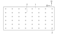
- FIG. 1 is a diagram showing an example of using spot current heating as a local rapid heating method, and is a schematic diagram showing an example of the arrangement of local heat affected regions in a decarburized annealed steel sheet for a grain-oriented electrical steel sheet according to this embodiment.
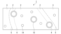
- FIG. 2 is a schematic diagram showing the distribution of Goss-oriented grains in a decarburization annealed steel sheet for grain-oriented electrical steel sheet according to one embodiment of the present invention.
- Patent Document 1 forms linear grooves on the surface of a steel sheet by etching, and increases the heating rate of the linear grooves during primary annealing to arrange a portion with a high ratio of Goss orientation grains (linear groove portion) and a portion with a high ratio of corresponding orientation grains (portion other than the linear grooves).
- this method it is difficult to increase the difference in heating rate during primary annealing between the linear groove portion and other portions, and the effect obtained is limited. Specifically, the difference in heating rate between the linear groove portion and the portion other than the linear grooves is not so large.
- the degree to which the sheet thickness of this portion is thinned by the formation of the grooves does not exceed about 10% of the original sheet thickness (because the normal groove depth is about 20 ⁇ m or less, which is about 10% or less of the sheet thickness), and considering the thermal conductivity of the steel sheet, the heating rate ratio is less than the sheet thickness ratio for the same heat input, so the ratio of Goss orientation grains in the linear groove portion is difficult to increase compared to the portion other than the linear grooves.
- this method increases the heating rate of the linear groove portion during the primary annealing, so the grain size of the Goss-oriented grains formed in the linear groove portion after the primary annealing does not increase in size compared to the overall average primary recrystallized grain size, but remains the same or finer.
- Patent Document 2 irradiates a laser beam toward the steel sheet surface before finish annealing.
- the laser beam irradiation area is only controlled to the grain boundaries of secondary recrystallization, and the orientation of the Goss orientation grains generated by primary recrystallization is not controlled.
- the area heated by laser irradiation is only the area near the surface where the laser is irradiated, and there is significant thermal diffusion to the surrounding areas, so it is usually not possible to ensure a thermal history that will recrystallize the steel sheet.
- Patent Document 3 irradiates a laser beam toward the surface of the steel sheet after cold rolling.
- the laser beam irradiation portion is only controlled to the grain boundary of secondary recrystallization, and the heating rate is not controlled, so the orientation of the Goss orientation grains generated by primary recrystallization is not controlled.
- the laser beam irradiation portion acts as a barrier to the growth of secondary recrystallized grains, thereby only reducing the grain size in the rolling direction of the secondary recrystallized grains, and a grain growth temperature range in the local heating region that is effective for increasing the diameter of Goss orientation grains in the local heating region is not secured.
- This method may be able to reduce the difference in the degree of orientation accumulation in the Goss orientation at the inner and outer periphery of the coil with different curvatures, but it does not obtain Goss orientation grains whose crystal orientation is close to the ideal Goss orientation. In other words, this method suppresses the decrease in magnetic flux density due to the increase in the grain size in the rolling direction of secondary recrystallized grains, but does not aim to fundamentally improve the orientation of the Goss orientation grains.
- a grain-oriented electrical steel sheet with excellent quality can be obtained by performing local rapid heating on the steel sheet to form a local heated region and then performing primary annealing (decarburization annealing).
- the local heated region formed before the primary annealing is arranged locally on the surface of the steel sheet.
- the crystalline structure of this local heated region consists of one or both of a recrystallized structure and a recovered structure at the end of the local rapid heating.
- the crystalline structure of the non-rapidly heated parts of the steel sheet surface other than the local heated region consists of a cold worked structure that remains cold rolled.
- the above-mentioned localized rapid heating has a heating rate of 500°C/sec or more, preferably 2000°C/sec or more, and more preferably 10000°C/sec or more.
- the frequency of coarse Goss orientation grains in the localized heating affected area is greater than that obtained by normal rapid heating of the entire plate. This characteristic is thought to be due to the fact that the peripheral area of the locally heated area is a processed structure that retains a lot of distortion. Specifically, when localized rapid heating is performed, the practical Goss orientation grains generated in the locally heated area preferentially encroach on the peripheral unrecrystallized area that retains a lot of distortion during the primary annealing, and grow in diameter. However, when the entire steel plate is heated, the generation and growth of recrystallized grains occurs uniformly within the steel plate, so it is thought that the above-mentioned enlargement does not occur.
- the Goss-oriented grains formed in the local heat-affected zone grow preferentially during secondary annealing.
- Many Goss-oriented grains are formed in the local heat-affected zone, including Goss-oriented grains that are close to the ideal Goss orientation, with particularly small angle deviations ⁇ and ⁇ , and that have large crystal grain sizes after primary annealing. During secondary recrystallization, these Goss-oriented grains grow preferentially.
- the Goss orientation grains that serve as the nuclei for secondary recrystallization are supplied to the local heat affected area, there is no need to form Goss orientation grains in the primary annealing in the matrix parts other than the local heat affected area, i.e., the local heat unaffected area. Therefore, as the heat treatment conditions for the primary annealing, a slow heating condition with a low heating rate may be adopted, and primary annealing conditions may be adopted that form many corresponding orientation grains with the ⁇ 111 ⁇ 112> orientation and ⁇ 411 ⁇ 148> orientation, which are easily eroded, in the local heat unaffected area.
- the heating rate for the primary annealing to 300°C/sec or less, many Goss orientation grains with large crystal grain size and close to the ideal Goss orientation are formed in the local heat affected area, while almost no Goss orientation grains are formed in the local heat unaffected area, and conversely, many corresponding orientation grains can be formed.
- spot current heating by electrical resistance heating
- spot electrodes are pressed against both sides of a steel sheet facing each other, and current is passed between the spot electrodes to spot current heating the electrode holding portion of the steel sheet.
- a steel having the composition shown in Table 1 was used, and a cold-rolled steel sheet with a sheet thickness of 0.22 mm was obtained by hot rolling and cold rolling. This steel sheet was subjected to spot current heating.
- the spot current heating was performed using a copper electrode with a diameter of 3 mm under the following conditions: current of 5.0 kA or less, which is a range in which the steel sheet surface does not melt, current time of 20 milliseconds to 80 milliseconds, electrode pressure of 50 kgf to 500 kgf, and electrode holding time after current application of 0.2 seconds.
- Spot current heating was performed on the surface of the cold-rolled steel sheet in a grid pattern with a pitch of 20 mm in the rolling direction and a pitch of 30 mm in the width direction (perpendicular to the rolling direction), forming a localized heating area.
- This cold-rolled steel sheet was subjected to decarburization annealing (primary annealing). In the decarburization annealing, the cold-rolled steel sheet was heated at a heating rate of 20°C/sec and held at 830°C for 90 seconds.
- Figure 1 shows an example of the arrangement of the local heat affected zone in a decarburized annealed steel sheet for grain-oriented electrical steel sheet according to this embodiment.
- the steel sheet 1, the local heat affected zone 2, the rolling direction 21, and the width direction (direction perpendicular to the rolling direction) 22 are shown diagrammatically.
- FIG. 1 is a schematic diagram showing the distribution of Goss orientation grains in the decarburized annealed steel sheet for grain-oriented electrical steel sheet according to this embodiment.
- the current-carrying electrode used for spot current heating is circular, and its diameter is preferably 0.5 mm ⁇ to 10 mm ⁇ , and more preferably 1 mm ⁇ to 5 mm ⁇ , in terms of circle equivalent diameter. Note that, although a circular current-carrying electrode was used in the above, it is sufficient to locally increase the heating rate of the cold-rolled steel sheet, form Goss-oriented grains in this region, and allow the grains to grow; the electrode shape may be other shapes, for example, elliptical or linear.
- the decarburization annealed steel sheet (steel sheet 1) for grain-oriented electrical steel sheet contains Goss orientation grains 14 and also contains coarse Goss orientation grains 15.
- the region containing the coarse Goss orientation grains 15 corresponds to the local heat affected region 2.
- FIG. 2 shows a schematic representation of the local heat affected region boundary 4 and the local heat affected region boundary 5, it is not easy to distinguish these boundaries by observing the structure.
- the region containing the coarse Goss orientation grains 15 can be considered as the local heat affected region 2.
- the above decarburized annealed steel sheet was further subjected to nitriding treatment, and then an annealing separator mainly composed of MgO was applied, followed by secondary annealing.
- the secondary annealing conditions were a hydrogen-nitrogen atmosphere, a heating rate of 15°C/hr (°C/hr), and holding at 1200°C-20hr (hr).
- the obtained steel sheet was subjected to macro-etching to reveal the grain boundaries.
- the decarburized annealed steel sheet according to this embodiment contains Goss orientation grains 14 as well as coarse Goss orientation grains 15. It is believed that the formation of coarse Goss orientation grains 15 close to the ideal Goss orientation with a size advantage is the cause of the good secondary recrystallization orientation.
- the characteristics of the decarburized annealed steel sheet for grain-oriented electrical steel sheet according to this embodiment will be specifically described.
- the decarburized annealed steel sheet shown in Figure 2 satisfies the following characteristics.
- the decarburization annealed steel sheet for the grain-oriented electrical steel sheet according to this embodiment is An area of at least 100 mm x 100 mm on the plate surface is defined as a divided section, and the divided section is divided into areas of 1 mm x 1 mm, and each section is defined as a divided small section;
- the average grain size of the crystal grains contained in the divided section is defined as aveD in units of ⁇ m,
- the ratio of the number of crystal grains having a grain size of 3.0 ⁇ aveD or more to the number of crystal grains contained in one divided small section is defined as F C
- the ratio of the number of crystal grains having a grain size of 3.0 ⁇ aveD or more to the number of crystal grains contained in the divided section is defined as aveF C ,
- the area ratio of the divided small section group I to the area of the divided section is 0.05% or more and 50% or less
- the deviation angle of the crystal orientation measured at the measurement point on the plate surface is represented as ( ⁇ ⁇ ),
- the crystal grains having the angle deviation ⁇ of 10° or less are defined as Goss oriented grains,
- a I GOSS area ratio of the Goss orientation grains contained in the divided sub-section group I to the area of the divided sub-section group I
- AveA GOSS the area ratio of the Goss orientation grains contained in the divided section to the area of the divided section
- the value of A I GOSS ⁇ aveA GOSS is 1.3 or more.
- the above crystal grains are determined as grain boundaries when the crystal orientation difference between adjacent measurement points is 1° or more.
- the above grain size refers to the circle equivalent diameter.
- the above average crystal grain size refers to the number average diameter.
- the angle deviation ⁇ is defined by the deviation angles ⁇ and ⁇ .
- the angle deviation ⁇ is often evaluated by three components, the deviation angles ⁇ , ⁇ , and ⁇ .
- the angle deviation ⁇ is defined by two components, the deviation angles ⁇ and ⁇ , excluding the deviation angle ⁇ , which has a small effect on the magnetic flux density.
- the area ratio of the divided small section group I to the area of the divided section being 0.05% or more means that, when a region of 100 mm x 100 mm is set as the divided section, 5 or more divided small sections in which coarse grains are preferably present (divided small sections in which the value of F C ⁇ aveF C is 1.3 or more) are included in 10,000 divided small sections.
- the value of A I GOSS ⁇ aveA GOSS being 1.3 or more means that the area ratio of Goss orientation grains included in the divided small section (divided small section group I) in which coarse grains are preferably present is significantly different from the area ratio of Goss orientation grains included in the matrix and is large.
- a decarburized annealed steel sheet satisfying these conditions means that there is a region (divided small section group I) in the matrix in which coarse grains are included and the area ratio of Goss orientation grains is large.
- a decarburized annealed steel sheet that satisfies the above conditions means that each of the divided sections arbitrarily provided within the steel sheet contains, on average, divided small sections (divided small section group I) that contain coarse crystal grains and have a large area ratio of Goss orientation grains.
- the area ratio of the divided small section group I to the area of the divided section is preferably 0.2% or more, more preferably 0.5% or more, and even more preferably 1% or more.
- the above area ratio is preferably 50% or less, since a region (matrix) is required for the coarse Goss orientation grains to preferentially undergo secondary recrystallization.
- the upper limit of this area ratio may be 40%, or 30%.
- the value of F C ⁇ aveF C being 1.3 or more means that, as described above, a region containing coarse crystal grains is preferably present in the matrix. According to the inventors' investigation, when normal whole plate heating is performed without local heating, even if the heating rate is increased to, for example, 10,000 ° C / sec, the value of F C ⁇ aveF C is only about 1.1 at most.
- the upper limit of the value of F C ⁇ aveF C is not particularly limited, and for example, this upper limit may be 100.
- the value of A I GOSS ⁇ aveA GOSS being 1.3 or more means that the area ratio of the Goss orientation grains contained in the divided small section group I is preferably large, as described above. According to the inventors' investigation, when normal heating of the entire plate is performed without local heating, even if the heating rate is increased to, for example, 10,000 ° C. / sec, a divided small section having a value of F C ⁇ aveF C of 1.3 or more is not formed in the first place, so the divided small section group I is not formed, and therefore the value of A I GOSS ⁇ aveA GOSS does not become 1.3 or more.
- the upper limit of the value of A I GOSS ⁇ aveA GOSS is not particularly limited, and for example, this upper limit may be 100.
- the divided sections including the divided small section group I that satisfies the above condition are preferably uniformly present over the entire decarburized annealed steel sheet.
- the above condition does not have to be satisfied over the entire sheet surface of the decarburized annealed steel sheet.
- the area ratio of the divided small section group I to the area of the divided sections is 0.05% or more and the value of A I GOSS ⁇ aveA GOSS is 1.3 or more).
- a grain-oriented electrical steel sheet with good magnetic properties can finally be obtained.
- the number of partitions that satisfy the above conditions is preferably 7 or more out of 10, and more preferably 8 or more.
- the upper limit for the number of partitions that satisfy the above conditions is 10, as the higher the number the better.
- the decarburization annealed steel sheet according to this embodiment When the decarburization annealed steel sheet according to this embodiment is used, during secondary recrystallization, among the many Goss orientation grains in the local heat affected zone, the coarse Goss orientation grains (Goss orientation grains with large crystal grain size) close to the ideal Goss orientation grow preferentially. Therefore, even if the secondary recrystallized grains are not allowed to grow large, the steel sheet can be dominated by secondary recrystallized grains close to the ideal Goss orientation. For example, when scattering the local heat affected zones on the steel sheet surface, the size, shape, and arrangement of the crystal grains after secondary annealing can be controlled by appropriately arranging the local heat affected zones on the steel sheet surface.
- the grain size of the Goss orientation grains at the end of secondary annealing will be small, and a steel sheet with excellent iron loss can be obtained.
- the Goss orientation grains that grow preferentially from the local heat-affected region have a crystal orientation close to the ideal Goss orientation, so good magnetic flux density can be obtained despite the small secondary recrystallized grain size.
- the magnetic flux density can be increased while suppressing the coarsening of the secondary recrystallized grain size, so that the magnetic domain width refinement by strain introduction or groove formation can be unnecessary or reduced.
- the magnetic domain refinement effect can be preferably obtained by the grain boundaries that increase with the refinement of the secondary recrystallized grain size, the magnetic domains are refined without applying the conventional magnetic domain control technology. Therefore, since it is not necessary to introduce strain into the steel sheet as in the conventional magnetic domain control technology, it is possible to prevent an increase in magnetostriction ( ⁇ P-P ).
- the grain-oriented electrical steel sheet using the decarburized annealed steel sheet according to the present embodiment can be used for applications requiring strain relief annealing at 800°C or more.
- the area ratio of the corresponding orientation grains is high.
- the area ratio of the corresponding orientation grains contained within the divided subdivision group II to the area of the divided subdivision group II is 10% or more and 50% or less.
- the coarse Goss orientation grains can preferably grow preferentially during secondary annealing.
- the above-mentioned area ratio of the corresponding orientation grains is preferably 12% or more, and more preferably 15% or more.
- the area ratio of corresponding orientation grains means the total area ratio of crystal grains that have a crystal orientation with a crystal orientation difference (disorientation) of 10° or less from a crystal orientation that has a corresponding orientation relationship of ⁇ 9 with the ideal Goss orientation ⁇ 110 ⁇ 001>, and corresponds to, for example, the total area ratio of ⁇ 778 ⁇ 447> orientation grains, ⁇ 111 ⁇ 112> orientation grains, and ⁇ 411 ⁇ 148> orientation grains.
- the above-mentioned average grain size aveD, number ratio F C , number ratio aveF C , deviation angle ⁇ , deviation angle ⁇ , area ratio A I GOSS of Goss oriented grains, area ratio aveA GOSS of Goss oriented grains, area ratio of corresponding orientation grains, etc. can be measured by the above-mentioned EBSD. If the region to be measured is larger than the region that can be measured by EBSD, the region to be measured can be divided and EBSD measurement can be performed multiple times. For example, the step size in the EBSD measurement can be set to 0.5 ⁇ m.
- the grain-oriented electrical steel sheet as a final product may have a chemical composition, in mass fraction, of 2.0% to 7.0% Si, with the remainder being Fe and impurities.
- this grain-oriented electrical steel sheet may contain publicly known optional elements in place of a portion of Fe in order to improve the magnetic properties.
- the lower limit may be 0%.
- the upper limit for the optional elements may be set to a range in which no significant decrease in magnetic flux density or iron loss occurs. The approximate upper limit for each optional element is listed below.
- the chemical composition of the final product, grain-oriented electrical steel sheet (base steel sheet), is, in mass%, as follows: C: 0.005% or less Si: 2.0 to 7.0% Mn: 1.00% or less, S and Se: 0.015% or less in total; Al: 0.065% or less, N: 0.005% or less; Nb, V, Mo, Ta, and W: 0.050% or less in total; Cu: 0.40% or less; Bi: 0.010% or less, B: 0.080% or less, P: 0.50% or less, Ti: 0.015% or less, Sn: 0.10% or less, Sb: 0.10% or less, Cr: 0.30% or less, Ni: 1.00% or less.
- the total content of S and Se means that at least one of S and Se is included, and that the total content is the total content of the elements.
- the total content of one or more of Nb, V, Mo, Ta, and W means that at least one of Nb, V, Mo, Ta, and W is included, and that the total content is the total content of the elements.
- the decarburization annealing and purification annealing during secondary recrystallization cause relatively large changes in the chemical composition (reduction in content).
- the content can be reduced to 50 ppm or less, and if purification annealing is carried out sufficiently, it can reach a level that cannot be detected by general analysis (1 ppm or less).
- impurities refer to elements that are inevitably mixed in from raw materials such as ore and scrap, or from the manufacturing environment, when industrially manufacturing steel sheets.
- the upper limit of the total impurity content may be, for example, 5%.
- the above chemical composition may be measured using a general analytical method for steel.
- the chemical composition may be measured using ICP-AES (Inductively Coupled Plasma-Atomic Emission Spectrometry).
- ICP-AES Inductively Coupled Plasma-Atomic Emission Spectrometry
- the chemical composition is determined by measuring a 35 mm square test piece taken from the steel plate using an ICP-AES or similar (measuring device) under conditions based on a previously prepared calibration curve.
- C and S may be measured using the combustion-infrared absorption method
- N may be measured using the inert gas fusion-thermal conductivity method.
- the chemical composition of the decarburized annealed steel sheet according to this embodiment contains, for example, the following elements:
- the decarburization annealed steel sheet according to this embodiment has a chemical composition, in mass%, of: C: 0 to 0.0050%, Si: 2.0 to 7.0%, Mn: 0.05-1.0%, S and Se: 0.003 to 0.035% in total, Al: 0.010-0.0650%, N: 0 to 0.012%, Nb, V, Mo, Ta, and W: 0 to 0.050% in total; Cu: 0 to 0.40%, Bi: 0 to 0.010%, B: 0 to 0.080%, P: 0-0.50%, Ti: 0 to 0.0150%, Sn: 0 to 0.10%, Sb: 0 to 0.10%, Cr: 0 to 0.30%, Ni: 0 to 1.0% and the remainder being Fe and impurities.
- C 0-0.0050% Carbon (C) is an effective element for controlling the primary recrystallization structure in the manufacturing process, but if its content in the final product is excessive, it will have a negative effect on the magnetic properties.
- the C content of a slab is The lower limit of the C content is 0.085% or less.
- C is purified in the decarburization annealing process and the finish annealing process, and the C content is 0.0050% or less.
- the lower limit of the C content is more than 0%. or may be 0.001%.
- Si 2.0-7.0%
- Silicon (Si) increases the electrical resistance of grain-oriented electrical steel sheets and reduces iron loss. If the Si content is less than 2.0%, ⁇ transformation occurs during final annealing, and the crystallization of the grain-oriented electrical steel sheets is reduced. On the other hand, if the Si content exceeds 7.0%, the cold workability decreases and cracks tend to occur during cold rolling.
- the upper limit of the Si content is preferably 4.5%, and more preferably 4.0%.
- Mn 0.05-1.0%
- Manganese (Mn) combines with S or Se to produce MnS or MnSe, and functions as an inhibitor.
- Mn is contained, the Mn content is within the range of 0.05 to 1.0%.
- the secondary recrystallization is stabilized.
- part of the inhibitor function is performed by nitrides of Nb group elements (Nb, V, Mo, Ta, and W).
- the strength of MnS or MnSe as a general inhibitor is controlled to be weak, and therefore the upper limit of the Mn content is preferably 0.50%, and more preferably 0.20%.
- S and Se 0.003 to 0.035% in total Sulfur (S) and selenium (Se) combine with Mn to produce MnS or MnSe, which functions as an inhibitor.
- S and Se When at least one of S and Se is contained, if the total content of S and Se is 0.003 to 0.035%, secondary recrystallization is stable. It is possible for a part of the inhibitor function to be borne by a nitride of an Nb group element. In this case, the strength of MnS or MnSe as a general inhibitor is controlled to be weak. For this reason, the preferred upper limit of the total content of S and Se is 0.025%, and more preferably 0.010%. If S and Se remain after the final annealing, they form compounds and deteriorate the iron loss. Therefore, it is preferable to reduce S and Se as much as possible by purification during the final annealing.
- the total content of S and Se means that at least one of S and Se is included, and is the total content.
- Al 0.010-0.0650%
- Aluminum (Al) combines with N to precipitate as (Al,Si)N, and functions as an inhibitor.
- the Al content is within the range of 0.010 to 0.0650%.
- AlN formed as an inhibitor by nitriding, which will be described later expands the secondary recrystallization temperature range, and secondary recrystallization is particularly stable in the high temperature range. Therefore, the Al content is 0.010 to 0.0650
- the lower limit of the Al content is preferably 0.020%, and more preferably 0.025%.
- the upper limit of the Al content is preferably 0.040%. and more preferably 0.035%.
- N 0-0.012% Nitrogen (N) combines with Al to function as an inhibitor. Since N can be incorporated by nitriding during the manufacturing process, no lower limit is specified. For example, the lower limit of the N content is set to more than 0%. On the other hand, when N is contained, if the N content exceeds 0.012%, blisters, which are a type of defect, are likely to occur in the steel sheet.
- the upper limit of the N content is preferably 0.010%, and more preferably 0.009%. N is purified in the final annealing process, and the N content becomes 0.005% or less after the final annealing process.
- the balance of the above chemical composition consists of Fe and impurities.
- impurities refers to elements that are mixed in from raw materials such as ore and scrap during industrial production of steel, or from the production environment, etc.
- the upper limit of the total impurity content may be, for example, 5%.
- the above-mentioned chemical composition may contain known optional elements in place of part of Fe, taking into consideration the strengthening of the inhibitor function through compound formation and the effect on magnetic properties.
- optional elements that may be contained in place of part of Fe include the following elements:
- Nb, V, Mo, Ta, and W 0 to 0.050%
- the total content of Nb (niobium), V (vanadium), Mo (molybdenum), Ta (tantalum), and W (tungsten) may be 0.050% or less.
- Nb group elements one or more of Nb, V, Mo, Ta, and W
- the effect of improving B8 is exhibited.
- the Nb group elements remain excessively in the base steel sheet, it may have a negative effect on the magnetic properties. Therefore, the total content of Nb, V, Mo, Ta, and W may be 0.050% or less.
- the total content of Nb group elements is 0.030% or less (preferably 0.003% or more and 0.030% or less), it is preferable because secondary recrystallization is started at an appropriate timing.
- the orientation of the secondary recrystallized grains that occur becomes very favorable, and it can be finally controlled to a structure favorable for the magnetic properties.
- Nb and Ta are preferable because their effects are strong.
- the lower limit is preferably 0.003%.
- the total content of Nb group elements is more preferably 0.004 to 0.020%. Even more preferably, it is 0.005 to 0.010%.
- the total content of Nb group elements means the total content including at least one of Nb, V, Mo, Ta, and W.
- the decarburized annealed steel sheet according to this embodiment contains, as optional elements, in mass%: Cu: 0 to 0.40%, Bi: 0 to 0.010%, B: 0 to 0.080%, P: 0-0.50%, Ti: 0 to 0.0150%, Sn: 0 to 0.10%, Sb: 0 to 0.10%, Cr: 0 to 0.30%, Ni: 0 to 1.0% may contain at least one of the following. Since these optional elements may be contained according to known purposes, there is no need to set a lower limit for the content of the optional elements, and the lower limit may be 0%.
- the chemical composition of the decarburized annealed steel sheet according to this embodiment can be measured by the above-mentioned analytical method, in the same way as the chemical composition of the grain-oriented electrical steel sheet as the final product.
- the method for manufacturing the decarburized annealed steel sheet according to this embodiment is not limited to the method described below.
- the manufacturing method described below is one example for manufacturing the decarburized annealed steel sheet according to this embodiment.
- the steps and quantitative conditions for each step shown below are examples adopted to demonstrate the feasibility of this embodiment, and this embodiment is not limited to these steps and quantitative values.
- the manufacturing method for the decarburized annealed steel sheet according to this embodiment may adopt various conditions as long as they do not deviate from the gist of this embodiment and achieve the purpose of this embodiment.
- the manufacturing method of the decarburized annealed steel sheet according to this embodiment can apply the conventional known manufacturing method of grain-oriented electrical steel sheet as a basic process.
- examples of conventional manufacturing methods of grain-oriented electrical steel sheet include a manufacturing method in which inhibitors such as MnS and AlN are formed by high-temperature slab heating, and a manufacturing method in which AlN inhibitors are formed by low-temperature slab heating and nitriding treatment.
- the manufacturing method of the decarburized annealed steel sheet according to this embodiment is not limited to a specific manufacturing method. Below, a method of applying nitriding treatment as a low-temperature slab heating process will be described.
- a slab is prepared.
- An example of a method for producing a slab is as follows. Molten steel is produced (smelted). A slab is produced using the molten steel. The slab may be produced by a continuous casting method. An ingot may be produced using the molten steel, and the ingot may be bloomed to produce a slab.
- the thickness of the slab is not particularly limited. The thickness of the slab is, for example, 150 to 350 mm. The thickness of the slab is preferably 220 to 280 mm. As the slab, a so-called thin slab having a thickness of 10 to 70 mm may be used. When a thin slab is used, rough rolling before finish rolling can be omitted in the hot rolling process.
- the above slab may contain the following elements in its chemical composition:
- Carbon (C) is an effective element for controlling the primary recrystallized structure in the manufacturing process, but if its content in the final product is excessive, it will have a detrimental effect on the magnetic properties.
- the preferred upper limit of the C content is 0.075%.
- C is purified in the decarburization annealing process and the finish annealing process to be 0.005% or less.
- the lower limit of the C content may be more than 0%, or may be 0.001%.
- Si 2.0-7.0%
- Silicon (Si) increases the electrical resistance of grain-oriented electrical steel sheets and reduces iron loss. If the Si content is less than 2.0%, ⁇ transformation occurs during final annealing, and the crystallization of the grain-oriented electrical steel sheets is reduced. On the other hand, if the Si content exceeds 7.0%, the cold workability decreases and cracks tend to occur during cold rolling.
- the upper limit of the Si content is preferably 4.5%, and more preferably 4.0%.
- Mn 0.05-1.00%
- Manganese (Mn) combines with S or Se to produce MnS or MnSe, and functions as an inhibitor.
- Mn is contained, the Mn content is within the range of 0.05 to 1.00%.
- the secondary recrystallization is stable. It is possible for part of the inhibitor function to be performed by a nitride of an Nb group element. In this case, the strength of MnS or MnSe as a general inhibitor is Therefore, the upper limit of the Mn content is preferably 0.50%, and more preferably 0.20%.
- At least one of S and Se 0.003 to 0.035% in total Sulfur (S) and selenium (Se) combine with Mn to produce MnS or MnSe, which functions as an inhibitor.
- S and Se When at least one of S and Se is contained, if the total content of S and Se is 0.003 to 0.035%, secondary recrystallization is stable. It is possible for a part of the inhibitor function to be borne by a nitride of an Nb group element. In this case, the strength of MnS or MnSe as a general inhibitor is controlled to be weak. For this reason, the preferred upper limit of the total content of S and Se is 0.025%, and more preferably 0.010%. If S and Se remain after the final annealing, they form compounds and deteriorate the iron loss. Therefore, it is preferable to reduce S and Se as much as possible by purification during the final annealing.
- the total content of S and Se means that at least one of S and Se is included, and is the total content.
- Al 0.010-0.065%
- Aluminum (Al) combines with N to precipitate as (Al,Si)N, and functions as an inhibitor.
- Al is contained, the Al content is within the range of 0.010 to 0.065%.
- AlN which acts as an inhibitor formed by nitriding as described below, expands the secondary recrystallization temperature range, and secondary recrystallization is particularly stable in the high temperature range. Therefore, the Al content is 0.010 to 0.065
- the lower limit of the Al content is preferably 0.020%, and more preferably 0.025%.
- the upper limit of the Al content is preferably 0.040%. and more preferably 0.035%.
- N 0.012% or less Nitrogen (N) combines with Al to function as an inhibitor. Since N can be contained by nitriding during the manufacturing process, no lower limit is specified. For example, the lower limit of the N content may be more than 0%, or may be 0.001%. On the other hand, when N is contained, if the N content exceeds 0.012%, blisters, which are a type of defect, tend to occur in the steel sheet. The preferred upper limit of the N content is 0.010%, and more preferably 0.009%. N is purified in the final annealing process, and becomes 0.005% or less after the final annealing process.
- the balance of the above chemical composition consists of Fe and impurities.
- impurities refers to elements that are mixed in from raw materials such as ore and scrap during industrial production of steel, or from the production environment, etc.
- the upper limit of the total impurity content may be, for example, 5%.
- the above-mentioned chemical composition may contain known optional elements in place of part of Fe, taking into consideration not only solving manufacturing problems, but also strengthening the inhibitor function through compound formation and the effect on magnetic properties.
- optional elements that may be contained in place of part of Fe include the following elements:
- Nb group elements 0.050% or less
- the total content of Nb group elements (one or more of Nb, V, Mo, Ta, and W) may be 0.050% or less.
- the total content of Nb group elements is 0.030% or less, since secondary recrystallization is started at an appropriate timing.
- the orientation of the secondary recrystallized grains generated becomes very favorable, and the structure can be finally controlled to be favorable for magnetic properties.
- Nb and Ta have a strong effect and are preferable.
- the total content of Nb group elements is more preferably 0.004 to 0.020%. Even more preferably, it is 0.005 to 0.010%.
- the total content of Nb group elements means the total content including at least one of Nb, V, Mo, Ta, and W.
- the slab also contains, as optional elements, in mass %: Cu: 0.40% or less, Bi: 0.010% or less, B: 0.080% or less, P: 0.50% or less, Ti: 0.015% or less, Sn: 0.10% or less, Sb: 0.10% or less, Cr: 0.30% or less, Ni: 1.00% or less. Since these optional elements may be contained according to known purposes, there is no need to set a lower limit for the content of the optional elements, and the lower limit may be 0%.
- the chemical composition of the above slabs can be measured by the above analytical method, just like the chemical composition of the final product, grain-oriented electrical steel sheet.
- the hot rolling process is a process in which a slab heated to a predetermined temperature (e.g., 1100 to 1400°C) is hot-rolled to obtain a hot-rolled steel sheet.
- a predetermined temperature e.g. 1100 to 1400°C
- the silicon steel material (slab) heated in the heating process is roughly rolled, and then finish-rolled to obtain a hot-rolled steel sheet with a predetermined thickness, for example, 1.8 to 3.5 mm. After the finish rolling is completed, the hot-rolled steel sheet is coiled at a predetermined temperature.
- the slab heating temperature should be 1100°C to 1280°C.
- the hot-rolled sheet annealing process is a process in which the hot-rolled steel sheet obtained in the hot rolling process is annealed under a predetermined temperature condition (for example, at 750 to 1200 ° C for 30 seconds to 10 minutes) to obtain an annealed steel sheet.
- Hot-rolled sheet annealing is generally performed to control the steel sheet structure such as the recrystallization rate, residual strain, and crystal grain size by annealing the hot-rolled steel sheet after the hot rolling process, and to preferably adjust the precipitate form in the steel.
- a high-temperature slab heating process it is a process for finally controlling the form of precipitates such as AlN, and conditions are adjusted so that they precipitate uniformly and finely.
- the hot-rolled sheet annealing for example, after heating the steel sheet to 1050 ° C to 1150 ° C, in order to properly precipitate AlN, etc., it may be cooled slowly to an intermediate temperature (850 ° C to 950 ° C) for 50 to 150 seconds, and then cooled with water.
- an intermediate temperature 850 ° C to 950 ° C
- the cold rolling process is a process in which the annealed steel sheet obtained in the hot-rolled sheet annealing process is subjected to one cold rolling or multiple cold rolling (two or more times) via annealing (intermediate annealing) to obtain a cold-rolled steel sheet having a thickness of, for example, 0.10 to 0.50 mm.
- the interpass temperature of the cold rolling may be set to about 100° C. to 300° C.
- Total cold rolling rate (%) (1 - thickness of steel plate after cold rolling / thickness of steel plate before cold rolling) x 100
- local rapid heating is performed on the cold-rolled steel sheet after the cold rolling process to form a local heating region.
- the rapid heating method is not particularly limited as long as it can locally heat the steel sheet.
- a method of heating by contacting a spot electrode with the front and back surfaces of the steel sheet and passing an electric current through the steel sheet a method of heating by irradiating the surface of the steel sheet with laser light or an electron beam, a method of locally heating by induction heating, a method of heating by contacting a hot piece, etc. can be adopted.
- each local heating region can be a dot-like region with a diameter of about 10 ⁇ m to 10 mm, or a linear region with a width of about 10 ⁇ m to 10 mm.
- the electrode used for current heating may be a circular electrode as described above, or a linear electrode.
- the minimum diameter and width of the size of the locally heated region depend on the shape of the spot electrode and the technology for reducing the focused diameter of the laser light or electron beam. In principle, it is possible to further reduce the size of the locally heated region, but considering that the current size of the nuclei of recrystallized grains is about 1 ⁇ m, it is believed that an effect can be obtained if the size of the locally heated region is 1 ⁇ m or more. From an industrial perspective, the above minimum diameter and width should be 10 ⁇ m or more. Regarding the size of the locally heated region, if the maximum diameter or width exceeds 10 mm, the area proportion of Goss orientation grains with relatively large angle deviations ⁇ and ⁇ that cannot grow outside the locally heated region increases. In this case, it becomes difficult to obtain the effect of local rapid heating.
- the heating rate should be 500°C/sec or more in the center of the locally heated region as viewed in the thickness direction and at 1/5 of the thickness of the steel plate. If the heating rate in the above region is 500°C/sec or more, the structure of the locally heated region can be preferably controlled to a recovered structure or a recrystallized structure.
- the above heating rate is preferably 2000°C/sec or more, and more preferably 10000°C/sec or more.
- the upper limit of the above heating rate is not particularly limited, and may be, for example, 1,000,000°C/sec.
- the aim is to have coarse Goss oriented grains in the local heat affected region after decarburization annealing, but if the heating rate during decarburization annealing is faster than the heating rate during local rapid heating, it is difficult to achieve the above objective. Therefore, although it depends on the magnitude of the heating rate, it is preferable to set the heating rate during local rapid heating to be equal to or higher than the heating rate during decarburization annealing.
- the 1/5 part of the thickness of the steel plate mentioned above refers to a depth equivalent to 1/5 of the thickness of the steel plate from the surface of the steel plate in the thickness direction.
- the maximum temperature reached should be 700°C or higher in the center of the locally heated region when viewed from the plate thickness direction and at 1/5 of the plate thickness of the steel plate. If the maximum temperature reached in the above region is 700°C or higher, the structure of the locally heated region can be preferably controlled to a recovered structure or a recrystallized structure.
- the above maximum temperature reached is preferably 800°C or higher, and more preferably 900°C or higher.
- the above maximum temperature reached should be below the melting point of the steel plate, for example, 1400°C or lower.
- the holding time from reaching the maximum temperature to cooling to 700°C at the center of the locally heated region as viewed from the thickness direction and at 1/5 of the thickness of the steel plate should be 0.1 seconds or more. If the holding time in the above region is 0.1 seconds or more, the structure of the locally heated region can be preferably controlled to a recovered structure or a recrystallized structure.
- the holding time is preferably 0.2 seconds or more, more preferably 0.3 seconds or more, and even more preferably 0.4 seconds or more.
- there is no particular limit to the upper limit of the holding time and it may be, for example, 10 seconds or less.
- the holding time from reaching the maximum temperature to cooling to 700°C has a fundamental effect on the formation of coarse Goss orientation grains close to the ideal Goss orientation.
- the method of local rapid heating is not particularly limited.
- local rapid heating may be performed by spot electrical current heating, laser irradiation, or electron beam irradiation.
- it is sufficient to control the heating rate, maximum temperature, and holding time described above so as to satisfy the above.
- a person skilled in the art can combine the various conditions of the local rapid heating method to control the desired heating rate, maximum temperature, and holding time.
- a person skilled in the art can perform a heat conduction analysis using the finite element method to control the heating rate and maximum temperature reached in the center of the localized heating area when viewed from the plate thickness direction and at 1/5 of the plate thickness of the steel plate.
- a person skilled in the art can control the above-mentioned holding time by adjusting the heat removal conditions after the maximum temperature is reached. For example, in the case of spot current heating, the electrode holding time after current is controlled, or the shape of the spot electrode can be changed to a shape suitable for heat removal.
- the irradiation speed can be adjusted, or the shape of the irradiation area can be changed to an ellipse or the like to gradient the irradiation energy from the center to the outer edge of the irradiation area.
- the heating by laser irradiation preferentially heats only the vicinity of the irradiated steel sheet surface, and the inside of the steel sheet is not easily heated.
- the heating by laser irradiation is non-contact heating, the heat is removed quickly after heating, and the temperature is not easily maintained. Therefore, when performing laser irradiation heating as local rapid heating, in order to recover or recrystallize the cold-worked structure in the laser irradiated region, it is necessary to control the conditions so that not only the surface of the steel sheet but also the inside of the steel sheet is heated, and the cooling rate is slowed down to relatively coarsen the subgrain structure in the laser irradiated region.
- the laser irradiation conditions for performing local rapid heating are completely different from the laser irradiation conditions for performing magnetic domain refinement. For example, even if the laser irradiation conditions for performing magnetic domain refinement (usually 0.5 to 50 mJ/mm 2 ) are applied to this embodiment, the structure of the locally heated region is not favorably controlled, and coarse Goss orientation grains close to the ideal Goss orientation are not formed in the steel sheet after the decarburization annealing process. The same applies to electron beam irradiation as to laser irradiation.
- the structure of the locally heated region is not favorably controlled, and coarse Goss oriented grains close to the ideal Goss orientation are not formed in the steel sheet after the decarburization annealing process.
- decarburization annealing process In the decarburization annealing step, the cold-rolled steel sheet after the local rapid heating step is subjected to decarburization annealing (primary annealing). This decarburization annealing increases the frequency of Goss-oriented grains formed in the local heat-affected zone, increases the grain size of the Goss-oriented grains, and preferably forms coarse Goss-oriented grains having an orientation close to the ideal Goss orientation.
- the decarburization annealing conditions may be a heating rate of 10 to 10,000°C/sec, an annealing temperature of 700 to 900°C, and an annealing time of 10 to 600 seconds.
- C contained in the cold-rolled steel sheet is removed. It is preferable to perform the decarburization annealing in a moist atmosphere in order to remove "C" contained in the cold-rolled steel sheet.
- the primary recrystallized grain size is not particularly limited, but is preferably 8 to 30 ⁇ m.
- the heating rate of decarburization annealing may be 10,000°C/sec or less, but it is preferable to slow down the heating rate of decarburization annealing to form ⁇ 111 ⁇ 112> orientation grains and ⁇ 411 ⁇ 148> orientation grains that are easily eroded into the matrix portion (region not affected by local heat).
- the heating rate of decarburization annealing is preferably 300°C/sec or less, more preferably 200°C/sec or less, and even more preferably 100°C/sec or less.
- the degree of oxidation (PH 2 O/PH 2 ) in the annealing atmosphere may be set to 0.01 to 0.15.
- the degree of oxidation PH 2 O/PH 2 can be defined as the ratio of the water vapor partial pressure PH 2 O to the hydrogen partial pressure PH 2 in the atmosphere.
- the above steps allow the manufacture of the decarburization annealed steel sheet for grain-oriented electrical steel sheet according to this embodiment.
- the decarburization annealed steel sheet according to this embodiment which is manufactured by controlling the conditions of each step in a composite and inseparable manner, has coarse Goss-oriented grains formed in a preferred form within the steel sheet.
- the following describes a method for manufacturing grain-oriented electrical steel sheet using the decarburized annealed steel sheet according to this embodiment.
- Nitriding is an effective treatment in a low-temperature slab heating process in which the slab heating temperature is 1280°C or less, and is an important step for adjusting the strength of the inhibitor in secondary recrystallization. Nitriding increases the nitrogen content of the steel sheet by about 40 to 200 ppm between the start of the decarburization treatment and the start of secondary recrystallization in the finish annealing.
- Examples of nitriding include a treatment of annealing in an atmosphere containing a gas with nitriding ability such as ammonia, and a treatment of finish annealing a decarburized annealed steel sheet coated with an annealing separator containing a powder with nitriding ability such as MnN.
- the amount of nitriding after the nitriding treatment is preferably 130 to 350 ppm, and more preferably 150 to 250 ppm.
- the annealing separator application process is a process of applying an annealing separator to the decarburized annealed steel sheet.
- an annealing separator mainly composed of MgO can be used as the annealing separator.
- the decarburized annealed steel sheet after application of the annealing separator is wound into a coil and finish-annealed in the next finish-annealing process.
- the final annealing process is a process in which the decarburized annealed steel sheet coated with the annealing separator is subjected to final annealing (secondary annealing) to cause secondary recrystallization.
- second annealing final annealing
- the growth of the primary recrystallized grains is suppressed by an inhibitor, and the secondary recrystallization is allowed to proceed, thereby preferentially growing ⁇ 100 ⁇ 001> oriented grains and dramatically improving the magnetic flux density.
- the heating rate during the heating process in the final annealing step is not particularly limited, but is preferably 3 to 7°C/hr (°C/hour). Furthermore, in the final annealing, the temperature range is 1000°C or higher and 1300°C or lower, and the temperature is maintained for 10 hours to 60 hours.
- the atmosphere during the final annealing may be, for example, a nitrogen atmosphere or a mixed atmosphere of nitrogen and hydrogen.
- a coating solution containing phosphoric acid or a phosphate, chromic anhydride or a chromate, and colloidal silica is applied to the steel sheet and baked (for example, at 350°C to 1150°C for 5 to 300 seconds) to form an insulating coating. do.
- the grain-oriented electrical steel sheet may be subjected to a magnetic domain refinement treatment for forming localized micro-distortion regions or grooves by a known method such as laser, plasma, mechanical method, etching, etc.
- a magnetic domain refinement treatment for forming localized micro-distortion regions or grooves by a known method such as laser, plasma, mechanical method, etching, etc.
- the grain-oriented electrical steel sheet manufactured using the decarburized annealed steel sheet according to the present embodiment has excellent magnetic flux density, but the coarsening of secondary recrystallized grains is suppressed, so that the magnetic domains are refined even without the magnetic domain refinement treatment.
- the conditions in the examples are one example of conditions adopted to confirm the feasibility and effects of the present invention, and the present invention is not limited to this one example of conditions.
- Various conditions can be adopted in the present invention as long as they do not deviate from the gist of the present invention and the object of the present invention is achieved.
- the chemical composition-adjusted slabs were used as the raw material to manufacture decarburized annealed steel sheets with the chemical compositions shown in Table 2. These chemical compositions were measured based on the method described above. In Table 2, "-" indicates that no control or manufacturing was carried out with the content in mind, and that no content measurements were carried out.
- the slabs were heated to 1150°C and subjected to hot rolling to obtain hot-rolled steel sheets with a thickness of 2.6 mm.
- the hot-rolled steel sheets were then heated to 1100°C and subsequently annealed at 900°C for hot-rolled sheet annealing, after which the sheets were pickled to remove the scale formed on the surface.
- These steel sheets were subjected to one cold rolling or multiple cold rolling with intermediate annealing in between to obtain cold-rolled steel sheets with a final thickness of 0.22 mm.
- the above cold-rolled steel sheets were subjected to localized rapid heating under the conditions shown in Tables 3 to 6.
- spot current heating a copper electrode with a diameter of 1 mm was used in the contact area with the steel sheet, and the electrode shape, electrode pressure, current, current duration, and electrode holding time after current were varied in a composite manner to control the heating rate, maximum temperature, and holding time from reaching the maximum temperature until cooling to 700°C (holding time above 700°C).
- the laser heating a fiber laser was used, and the focal spot diameter of the laser light in the rolling direction (i.e., the diameter including 86% of the laser output) was set to 30 ⁇ m (except for Tests No. 43 and No. 44).
- the laser irradiation energy density, laser scanning speed, and shape of the laser irradiation area were varied in a composite manner to control the heating rate, maximum temperature, and holding time above 700°C.
- Those skilled in the art can combine the conditions of the localized rapid heating method to control the desired heating rate, maximum temperature, and holding time above 700°C.
- test No. 41 the laser beam was elongated in the scanning direction, and the holding time from reaching the maximum temperature to cooling to 700 ° C. during local rapid heating was controlled to 0.2 seconds, so that coarse Goss orientation grains having an orientation close to the ideal Goss orientation were formed in the locally heated area.
- test No. 42 general laser irradiation conditions for magnetic domain refinement were applied.
- test No. 43 the focusing spot diameter was set to 0.5 mm, the laser irradiation energy density was set to 2.0 J/mm 2 , and the laser beam irradiation portion was controlled so that it would eventually become the grain boundary of the secondary recrystallized grain.
- test No. 43 the focusing spot diameter was set to 0.5 mm, the laser irradiation energy density was set to 2.0 J/mm 2 , and the laser beam irradiation portion was controlled so that it would eventually become the grain boundary of the secondary recrystallized grain.
- the focusing spot diameter was set to 0.5 mm
- the laser irradiation energy density was set to 30.0 J/mm 2
- the laser beam irradiation portion was controlled so that it would eventually become the grain boundary of the secondary recrystallized grain.
- the localized heating conditions “Linear or dotted” indicate the shape of the localized heated area on the surface of the cold-rolled steel sheet
- the localized heating conditions “Rolling direction spacing” and “Width direction spacing” indicate the spacing in the rolling direction and the direction perpendicular to the rolling direction at which the localized heated areas are arranged on the surface of the cold-rolled steel sheet.
- the localized heated areas are arranged at equal intervals in the rolling direction and the direction perpendicular to the rolling direction. For example, if both the "Rolling direction spacing" and the "Width direction spacing" are 100 mm or less, localized heated areas are arranged in all divided sections.
- the cold-rolled steel sheets after the localized rapid heating were subjected to decarburization annealing under the conditions shown in Tables 3 to 6.
- the degree of oxidation (PH 2 O/PH 2 ) in the annealing atmosphere (furnace atmosphere) was set to 0.13.
- the decarburized annealed steel sheets produced were nitrided at 750°C in a nitrogen-hydrogen-ammonia atmosphere to bring the nitrogen content of the steel sheets to 220 ppm.
- An annealing separator mainly composed of MgO was then applied and finish annealed.
- the steel sheets were heated to 1000°C at 15°C/hr (°C/hour) in a mixed atmosphere of hydrogen and nitrogen, then heated to 1200°C at the heating rates shown in Tables 3 to 6, and held at 1200°C for 20 hr in a hydrogen atmosphere.
- the steel sheet After final annealing, the steel sheet is coated with an insulating coating solution made mainly of colloidal silica and phosphate, with chromic anhydride added as needed, and baked to form an insulating coating.
- an insulating coating solution made mainly of colloidal silica and phosphate, with chromic anhydride added as needed, and baked to form an insulating coating.
- Secondary recrystallized grain size of grain-oriented electrical steel sheet The secondary recrystallized grain size of the grain-oriented electrical steel sheet was measured based on the cutting method specified in JIS G0551:2020. Note that the secondary recrystallized grain size (average grain size) in the rolling direction was measured as the secondary recrystallized grain size. A secondary recrystallized grain size (average grain size) of 65 ⁇ m or less in the rolling direction was judged to be acceptable.
- the decarburized annealed steel sheets according to the present invention had a favorable control of the area ratio of the divided small section group I to the area of the divided section and the value of A I GOSS ⁇ aveA GOSS .
- All of these examples of the present invention as grain-oriented electrical steel sheets, exhibited excellent magnetic flux density despite the suppression of coarsening of the secondary recrystallized grain size.
- the suppression of coarsening of the secondary recrystallized grain size was achieved in these grain-oriented electrical steel sheets, they also had excellent iron loss and magnetostriction.
- the above aspect of the present invention makes it possible to provide a decarburized annealed steel sheet for grain-oriented electrical steel that can increase magnetic flux density while suppressing coarsening of secondary recrystallized grains, and therefore has high industrial applicability.
Landscapes
- Chemical & Material Sciences (AREA)
- Engineering & Computer Science (AREA)
- Materials Engineering (AREA)
- Mechanical Engineering (AREA)
- Metallurgy (AREA)
- Organic Chemistry (AREA)
- Physics & Mathematics (AREA)
- Thermal Sciences (AREA)
- Crystallography & Structural Chemistry (AREA)
- Electromagnetism (AREA)
- Manufacturing & Machinery (AREA)
- Power Engineering (AREA)
- Manufacturing Of Steel Electrode Plates (AREA)
- Soft Magnetic Materials (AREA)
Abstract
Description
本願は、2023年6月29日に、日本に出願された特願2023-106859号に基づき優先権を主張し、その内容をここに援用する。
即ち、従来の工程制御条件では、ゴス方位粒の存在頻度とゴス方位粒に蚕食されやすい対応方位粒の存在頻度とを独立に制御することができていなかった。
θ=(α2+β2+γ2)1/2 (式1)
板面上の少なくとも100mm×100mmの領域を分割区画と定義し、前記分割区画内を1mm×1mmの領域に細分して各区画を分割小区画と定義し、
前記分割区画内に含まれる結晶粒の平均粒径を単位μmでaveDと定義し、
1つの分割小区画内に含まれる結晶粒数に対してこの分割小区画内に含まれる粒径が3.0×aveD以上となる結晶粒数の個数割合をFCと定義し、前記分割区画内に含まれる結晶粒数に対して前記分割区画内に含まれる粒径が3.0×aveD以上となる結晶粒数の個数割合をaveFCと定義し、
FC÷aveFCの値が1.3以上となる分割小区画を合わせて分割小区画グループIと定義したとき、
前記分割区画の面積に対して前記分割小区画グループIの面積割合が0.05%以上50%以下であり、且つ
圧延面法線方向を回転軸とする理想ゴス方位からのずれ角をαと定義し、
圧延直角方向を回転軸とする理想ゴス方位からのずれ角をβと定義し、
板面上の測定点で測定する結晶方位のずれ角を(α β)と表し、
前記測定点での角度偏差をφ=(α2+β2)1/2と定義し、
前記角度偏差φが10°以下である結晶粒をゴス方位粒と定義し、
前記分割小区画グループIの面積に対して前記分割小区画グループI内に含まれるゴス方位粒の面積割合をAI GOSSと定義し、前記分割区画の面積に対して前記分割区画内に含まれるゴス方位粒の面積割合をaveAGOSSと定義したとき、
AI GOSS÷aveAGOSSの値が1.3以上である。
[2]上記[1]に記載の方向性電磁鋼板用の脱炭焼鈍鋼板では、
理想ゴス方位に対してΣ9対応方位関係にある結晶方位からの方位差が10°以内である結晶粒を対応方位粒と定義し、
前記分割区画のうちで前記分割小区画グループIを除く分割小区画を分割小区画グループIIと定義したとき、
前記分割小区画グループIIの面積に対して前記分割小区画グループII内に含まれる対応方位粒の面積割合が10%以上50%以下であってもよい。
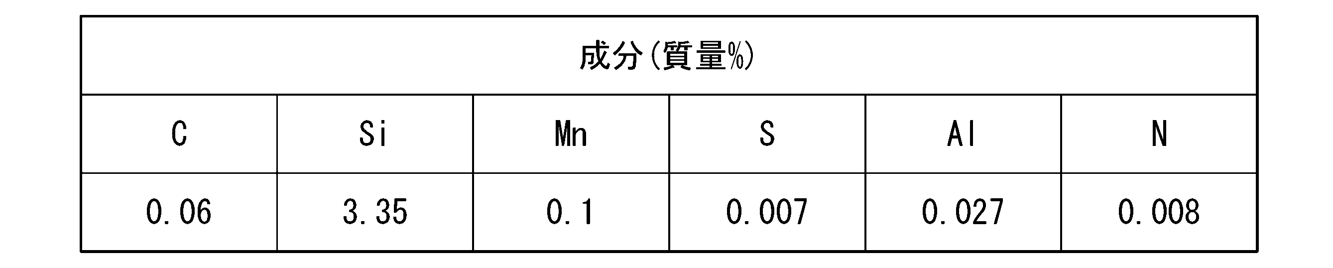
板面上の少なくとも100mm×100mmの領域を分割区画と定義し、この分割区画内を1mm×1mmの領域に細分して各区画を分割小区画と定義し、
上記分割区画内に含まれる結晶粒の平均粒径を単位μmでaveDと定義し、
1つの分割小区画内に含まれる結晶粒数に対してこの分割小区画内に含まれる粒径が3.0×aveD以上となる結晶粒数の個数割合をFCと定義し、上記分割区画内に含まれる結晶粒数に対して上記分割区画内に含まれる粒径が3.0×aveD以上となる結晶粒数の個数割合をaveFCと定義し、
FC÷aveFCの値が1.3以上となる分割小区画を合わせて分割小区画グループIと定義したとき、
上記分割区画の面積に対して上記分割小区画グループIの面積割合が0.05%以上50%以下となり、且つ
圧延面法線方向を回転軸とする理想ゴス方位からのずれ角をαと定義し、
圧延直角方向を回転軸とする理想ゴス方位からのずれ角をβと定義し、
板面上の測定点で測定する結晶方位のずれ角を(α β)と表し、
上記測定点での角度偏差をφ=(α2+β2)1/2と定義し、
上記角度偏差φが10°以下である結晶粒をゴス方位粒と定義し、
上記分割小区画グループIの面積に対して上記分割小区画グループI内に含まれるゴス方位粒の面積割合をAI GOSSと定義し、上記分割区画の面積に対して上記分割区画内に含まれるゴス方位粒の面積割合をaveAGOSSと定義したとき、
AI GOSS÷aveAGOSSの値が1.3以上となる。
最終製品としての方向性電磁鋼板は、化学組成として、質量分率で、Si:2.0%~7.0%を含有し、残部がFeおよび不純物からなればよい。
C:0.005%以下
Si:2.0~7.0%
Mn:1.00%以下、
S及びSe:合計で0.015%以下、
Al:0.065%以下、
N:0.005%以下
Nb、V、Mo、Ta、及びW:合計で、0.050%以下
Cu:0.40%以下、
Bi:0.010%以下、
B:0.080%以下、
P:0.50%以下、
Ti:0.015%以下、
Sn:0.10%以下、
Sb:0.10%以下、
Cr:0.30%以下、
Ni:1.00%以下
の少なくとも1種を含有してもよい。
C:0~0.0050%、
Si:2.0~7.0%、
Mn:0.05~1.0%、
S及びSe:合計で0.003~0.035%、
Al:0.010~0.0650%、
N:0~0.012%、
Nb、V、Mo、Ta、及びW:合計で0~0.050%、
Cu:0~0.40%、
Bi:0~0.010%、
B:0~0.080%、
P:0~0.50%、
Ti:0~0.0150%、
Sn:0~0.10%、
Sb:0~0.10%、
Cr:0~0.30%、
Ni:0~1.0%
を含有し、残部がFeおよび不純物からなればよい。
炭素(C)は、製造工程においては一次再結晶組織の制御に有効な元素であるものの、最終製品への含有量が過剰であると磁気特性に悪影響を及ぼす。例えば、スラブのC含有量は0.085%以下である。ただ、Cは脱炭焼鈍工程及び仕上げ焼鈍工程で純化され、0.0050%以下となる。工業生産における生産性を考慮すると、C含有量の下限は0%超であってもよく、0.001%であってもよい。
シリコン(Si)は、方向性電磁鋼板の電気抵抗を高めて鉄損を低下させる。Si含有量が2.0%未満であれば、仕上げ焼鈍時にγ変態が生じて、方向性電磁鋼板の結晶方位が損なわれてしまう。一方、Si含有量が7.0%を超えれば、冷間加工性が低下して、冷間圧延時に割れが発生しやすくなる。Si含有量の好ましい下限は2.5%であり、さらに好ましくは3.0%である。Si含有量の好ましい上限は4.5%であり、さらに好ましくは4.0%である。
マンガン(Mn)はS又はSeと結合して、MnS、又は、MnSeを生成し、インヒビターとして機能する。Mnを含有させる場合、Mn含有量が0.05~1.0%の範囲内にある場合に、二次再結晶が安定する。なお、インヒビターの機能の一部をNb群元素(Nb、V、Mo、Ta、及びW)の窒化物によって担うことが可能である。この場合は、一般的なインヒビターとしてのMnS、又は、MnSe強度は弱めに制御する。このため、Mn含有量の好ましい上限は0.50%であり、さらに好ましくは0.20%である。
硫黄(S)及びセレン(Se)は、Mnと結合して、MnS又はMnSeを生成し、インヒビターとして機能する。S及びSeの少なくとも一方を含有させる場合、S及びSeの含有量が合計で0.003~0.035%であれば、二次再結晶が安定する。なお、インヒビターの機能の一部をNb群元素の窒化物によって担うことが可能である。この場合は、一般的なインヒビターとしてのMnS、又は、MnSe強度は弱めに制御する。このため、S及びSe含有量の合計の好ましい上限は0.025%であり、さらに好ましくは0.010%である。S及びSeは仕上げ焼鈍後に残留すると化合物を形成し、鉄損を劣化させる。そのため、仕上げ焼鈍中の純化により、S及びSeをできるだけ少なくすることが好ましい。
アルミニウム(Al)は、Nと結合して(Al、Si)Nとして析出し、インヒビターとして機能する。Alを含有させる場合、Al含有量が0.010~0.0650%の範囲内にある場合に、後述の窒化により形成されるインヒビターとしてのAlNは二次再結晶温度域を拡大し、特に高温域での二次再結晶が安定する。したがって、Al含有量は0.010~0.0650%である。Al含有量の好ましい下限は0.020%であり、さらに好ましくは0.025%である。二次再結晶の安定性の観点から、Al含有量の好ましい上限は0.040%であり、さらに好ましくは0.035%である。
窒素(N)は、Alと結合してインヒビターとして機能する。Nは製造工程の途中で窒化により含有させることが可能であるため下限は規定しない。例えば、N含有量の下限は0%超であってもよく、0.001%であってもよい。一方、Nを含有させる場合、N含有量が0.012%を超えれば、鋼板中に欠陥の一種であるブリスタが発生しやすくなる。N含有量の好ましい上限は0.010%であり、さらに好ましくは0.009%である。Nは仕上げ焼鈍工程で純化され、仕上げ焼鈍工程後には0.005%以下となる。
Nb(ニオブ)、V(バナジウム)、Mo(モリブデン)、Ta(タンタル)、W(タングステン)の合計含有量は0.050%以下であればよい。Nb群元素(Nb、V、Mo、Ta、及びWの1種以上)をインヒビターの一部として活用する場合、B8の向上効果を発揮する。一方、母材鋼板にNb群元素が過剰に残留すると、磁気特性に悪影響を及ぼすことがある。そのため、Nb、V、Mo、Ta、及びWの合計含有量は、0.050%以下であればよい。さらに、Nb群元素の合計含有量が0.030%以下(好ましくは0.003%以上、0.030%以下)であると、適切なタイミングで二次再結晶を開始させるので好ましい。また、発生する二次再結晶粒の方位が非常に好ましいものとなり、最終的に磁気特性にとって好ましい組織に制御できる。特に、Nb及びTaはその効果が強く好ましい。Nb群元素の合計含有量は下限値を設ける必要がなく、下限値が0%でもよい。この下限値は、0.003%であることが好ましい。
Cu:0~0.40%、
Bi:0~0.010%、
B:0~0.080%、
P:0~0.50%、
Ti:0~0.0150%、
Sn:0~0.10%、
Sb:0~0.10%、
Cr:0~0.30%、
Ni:0~1.0%
の少なくとも1種を含有してもよい。
これら任意元素は、公知の目的に応じて含有させればよいため、任意元素の含有量の下限値を設ける必要はなく、下限値が0%でもよい。
鋳造工程では、スラブを準備する。スラブの製造方法の一例は次のとおりである。溶鋼を製造(溶製)する。溶鋼を用いてスラブを製造する。連続鋳造法によりスラブを製造してもよい。溶鋼を用いてインゴットを製造し、インゴットを分塊圧延してスラブを製造してもよい。スラブの厚さは、特に限定されない。スラブの厚さは、たとえば、150~350mmである。スラブの厚さは、好ましくは、220~280mmである。スラブとして、厚さが10~70mmの、いわゆる薄スラブを用いてもよい。薄スラブを用いる場合、熱間圧延工程において、仕上げ圧延前の粗圧延を省略できる。
炭素(C)は、製造工程においては一次再結晶組織の制御に有効な元素であるものの、最終製品への含有量が過剰であると磁気特性に悪影響を及ぼす。したがって、C含有量は0.085%以下である。C含有量の好ましい上限は0.075%である。Cは脱炭焼鈍工程及び仕上げ焼鈍工程で純化され、0.005%以下となる。Cを含む場合、工業生産における生産性を考慮すると、C含有量の下限は0%超であってもよく、0.001%であってもよい。
シリコン(Si)は、方向性電磁鋼板の電気抵抗を高めて鉄損を低下させる。Si含有量が2.0%未満であれば、仕上げ焼鈍時にγ変態が生じて、方向性電磁鋼板の結晶方位が損なわれてしまう。一方、Si含有量が7.0%を超えれば、冷間加工性が低下して、冷間圧延時に割れが発生しやすくなる。Si含有量の好ましい下限は2.5%であり、さらに好ましくは3.0%である。Si含有量の好ましい上限は4.5%であり、さらに好ましくは4.0%である。
マンガン(Mn)はS又はSeと結合して、MnS、又は、MnSeを生成し、インヒビターとして機能する。Mnを含有させる場合、Mn含有量が0.05~1.00%の範囲内にある場合に、二次再結晶が安定する。なお、インヒビターの機能の一部をNb群元素の窒化物によって担うことが可能である。この場合は、一般的なインヒビターとしてのMnS、又は、MnSe強度は弱めに制御する。このため、Mn含有量の好ましい上限は0.50%であり、さらに好ましくは0.20%である。
硫黄(S)及びセレン(Se)は、Mnと結合して、MnS又はMnSeを生成し、インヒビターとして機能する。S及びSeの少なくとも一方を含有させる場合、S及びSeの含有量が合計で0.003~0.035%であれば、二次再結晶が安定する。なお、インヒビターの機能の一部をNb群元素の窒化物によって担うことが可能である。この場合は、一般的なインヒビターとしてのMnS、又は、MnSe強度は弱めに制御する。このため、S及びSe含有量の合計の好ましい上限は0.025%であり、さらに好ましくは0.010%である。S及びSeは仕上げ焼鈍後に残留すると化合物を形成し、鉄損を劣化させる。そのため、仕上げ焼鈍中の純化により、S及びSeをできるだけ少なくすることが好ましい。
アルミニウム(Al)は、Nと結合して(Al、Si)Nとして析出し、インヒビターとして機能する。Alを含有させる場合、Al含有量が0.010~0.065%の範囲内にある場合に、後述の窒化により形成されるインヒビターとしてのAlNは二次再結晶温度域を拡大し、特に高温域での二次再結晶が安定する。したがって、Al含有量は0.010~0.065%である。Al含有量の好ましい下限は0.020%であり、さらに好ましくは0.025%である。二次再結晶の安定性の観点から、Al含有量の好ましい上限は0.040%であり、さらに好ましくは0.035%である。
窒素(N)は、Alと結合してインヒビターとして機能する。Nは製造工程の途中で窒化により含有させることが可能であるため下限は規定しない。例えば、N含有量の下限は0%超であってもよく、0.001%であってもよい。一方、Nを含有させる場合、N含有量が0.012%を超えれば、鋼板中に欠陥の一種であるブリスタが発生しやすくなる。N含有量の好ましい上限は0.010%であり、さらに好ましくは0.009%である。Nは仕上げ焼鈍工程で純化され、仕上げ焼鈍工程後には0.005%以下となる。
Nb群元素(Nb、V、Mo、Ta、及びWの1種以上)の合計含有量は0.050%以下であればよい。Nb群元素をインヒビターの一部として活用する場合、Nb群元素の合計含有量が0.030%以下であると、適切なタイミングで二次再結晶を開始させるので好ましい。また、発生する二次再結晶粒の方位が非常に好ましいものとなり、最終的に磁気特性にとって好ましい組織に制御できる。特に、Nb及びTaはその効果が強く好ましい。Nb群元素の合計含有量は下限値を設ける必要がなく、下限値が0%でもよい。この下限値は、0.003%であることが好ましい。
Cu:0.40%以下、
Bi:0.010%以下、
B:0.080%以下、
P:0.50%以下、
Ti:0.015%以下、
Sn:0.10%以下、
Sb:0.10%以下、
Cr:0.30%以下、
Ni:1.00%以下
の少なくとも1種を含有してもよい。
これら任意元素は、公知の目的に応じて含有させればよいため、任意元素の含有量の下限値を設ける必要はなく、下限値が0%でもよい。
熱間圧延工程は、所定の温度(例えば1100~1400℃)に加熱されたスラブの熱間圧延を行い、熱延鋼板を得る工程である。熱間圧延工程では、例えば、加熱工程で加熱された珪素鋼素材(スラブ)の粗圧延を行った後、仕上げ圧延を行って所定厚さ、例えば、1.8~3.5mmの熱延鋼板とする。仕上げ圧延終了後、熱延鋼板を所定の温度で巻き取る。
熱延板焼鈍工程は、熱間圧延工程で得た熱延鋼板を所定の温度条件(例えば750~1200℃で30秒間~10分間)で焼鈍して、焼鈍鋼板を得る工程である。熱延板焼鈍は、一般的に、熱間圧延工程後の熱延鋼板を焼鈍することにより、再結晶率や残存歪や結晶粒径などの鋼板組織を制御し、また鋼中の析出物形態を好ましく調整するために実施される。例えば、高温スラブ加熱プロセスにおいては、AlNなどの析出物の形態を最終的に制御する工程であり、均一かつ微細に析出するように条件調整する。熱延板焼鈍として、例えば、鋼板を1050℃~1150℃に加熱した後、AlNなどを適正に析出させるため、50~150秒かけて中間温度(850℃~950℃)まで緩冷却した後、水冷却してもよい。
冷間圧延工程は、熱延板焼鈍工程で得た焼鈍鋼板を、1回の冷間圧延、又は焼鈍(中間焼鈍)を介して複数回(2回以上)の冷間圧延(例えば総冷延率で80~95%)により、例えば、0.10~0.50mmの厚さを有する冷延鋼板を得る工程である。磁気特性を改善するために、例えば、冷間圧延のパス間温度を100℃~300℃程度にしてもよい。
総冷延率(%)=(1-冷間圧延後の鋼板の板厚/冷間圧延前の鋼板の板厚)×100
本実施形態では、冷間圧延工程後の冷延鋼板に対して、局所加熱領域を形成するための局所急速加熱を行う。急速加熱方法としては、鋼板を局所的に加熱できるものであればよく、特に限定しない。例えば、鋼板の表裏面にスポット電極を接触させて鋼板内に電流を通電して加熱する方法、レーザー光や電子ビームなどを鋼板表面に照射して加熱する方法、誘導加熱によって局所的に加熱する方法、熱片を接触させて加熱する方法などを採用することができる。個々の局所加熱領域の大きさとしては、直径が10μm~10mm程度の点状領域、あるいは幅が10μm~10mm程度の線状領域とすることができる。また、通電加熱に用いる電極は、上記のように円形状の電極としてもよく、または線状の電極としてもよい。
脱炭焼鈍工程では、局所急速加熱工程後の冷延鋼板に対して、脱炭焼鈍(一次焼鈍)を行う。この脱炭焼鈍により、局所加熱影響領域に形成されるゴス方位粒の存在頻度が増大し、ゴス方位粒の粒径が増大し、理想ゴス方位に近い方位を持つ粗大ゴス方位粒が好ましく形成される。脱炭焼鈍条件としては、加熱速度を10~10000℃/秒、焼鈍温度を700~900℃、焼鈍時間を10~600秒とすればよい。また、冷延鋼板に脱炭焼鈍を行うことで、冷延鋼板中に含まれるCが除去される。脱炭焼鈍は、冷延鋼板中に含まれる「C」を除去するために、湿潤雰囲気中で行うことが好ましい。
窒化処理は、スラブ加熱温度が1280℃以下の低温スラブ加熱プロセスで有効な処理であり、二次再結晶におけるインヒビターの強度を調整するために重要な工程である。窒化処理は、脱炭処理の開始から、仕上げ焼鈍における二次再結晶の開始までの間に、鋼板の窒素量を40~200ppm程度増加させる。窒化処理としては、例えば、アンモニア等の窒化能のあるガスを含有する雰囲気中で焼鈍する処理、MnN等の窒化能を有する粉末を含む焼鈍分離剤を塗布した脱炭焼鈍鋼板を仕上げ焼鈍する処理等が例示される。窒化処理後の窒化量は130~350ppmとすることが好ましく、さらには150~250ppmとすることが好ましい。
焼鈍分離剤塗布工程は、脱炭焼鈍鋼板に焼鈍分離剤を塗布する工程である。焼鈍分離剤としては、例えば、MgOを主成分とする焼鈍分離剤を用いることができる。焼鈍分離剤を塗布後の脱炭焼鈍鋼板は、コイル状に巻取った状態で、次の仕上げ焼鈍工程で仕上げ焼鈍される。
仕上げ焼鈍工程は、焼鈍分離剤が塗布された脱炭焼鈍鋼板に仕上げ焼鈍(二次焼鈍)を施し、二次再結晶を生じさせる工程である。この工程は、一次再結晶粒の成長をインヒビターにより抑制した状態で二次再結晶を進行させることによって、{100}<001>方位粒を優先成長させ、磁束密度を飛躍的に向上させる。
鋼板に、りん酸あるいはりん酸塩、無水クロム酸あるいはクロム酸塩およびコロイド状シリカを含むコーティング溶液を塗布して焼き付けて(例えば、350℃~1150℃で5~300秒間)、絶縁被膜を形成する。
方向性電磁鋼板には、必要に応じて、レーザー、プラズマ、機械的方法、エッチングなど、公知の手法により、局所的な微小歪領域または溝を形成する磁区細分化処理を施してもよい。ただ、本実施形態に係る脱炭焼鈍鋼板を用いて製造された方向性電磁鋼板は、優れた磁束密度を有するにもかかわらず、二次再結晶粒径の粗大化が抑制されているので、磁区細分化処理を行わなくても磁区が細分化されている。
方向性電磁鋼板の二次再結晶粒径は、JIS G0551:2020に規定された切断法に基づいて測定した。なお、上記の二次再結晶粒径として、圧延方向の二次再結晶粒径(平均粒径)を測定した。圧延方向の二次再結晶粒径(平均粒径)が65μm以下である場合を合格と判断した。
方向性電磁鋼板の磁気特性は、JIS C 2556:2015に規定された単板磁気特性試験法(SST:Single Sheet Tester)に基づいて測定した。
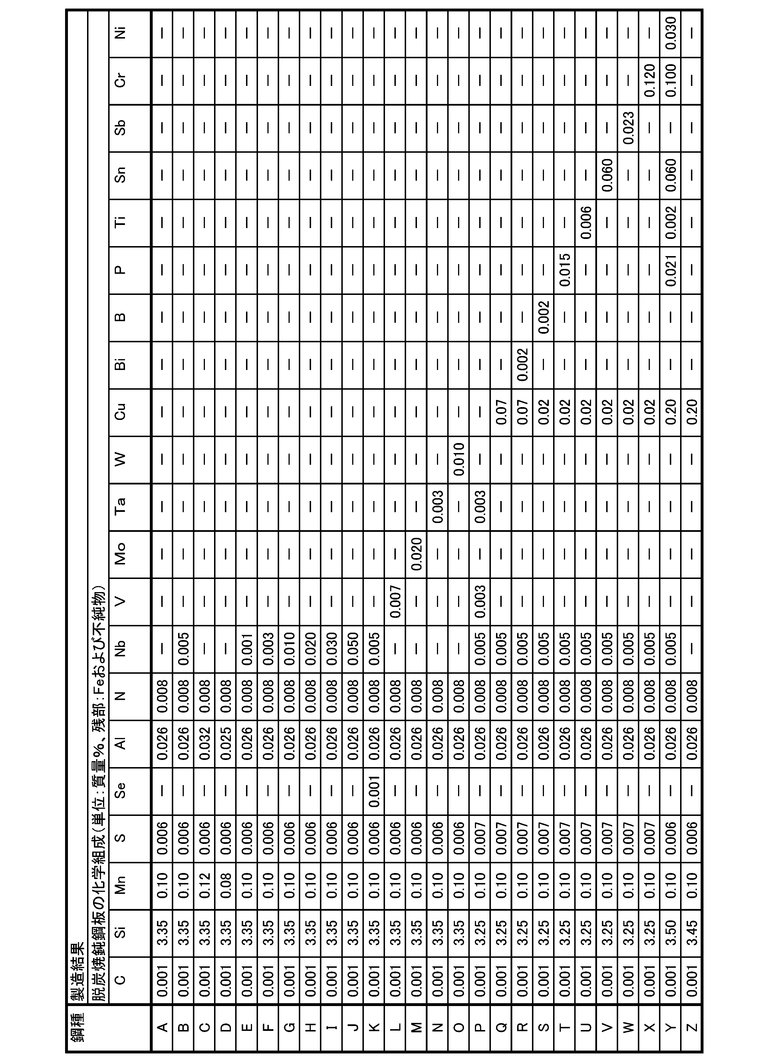
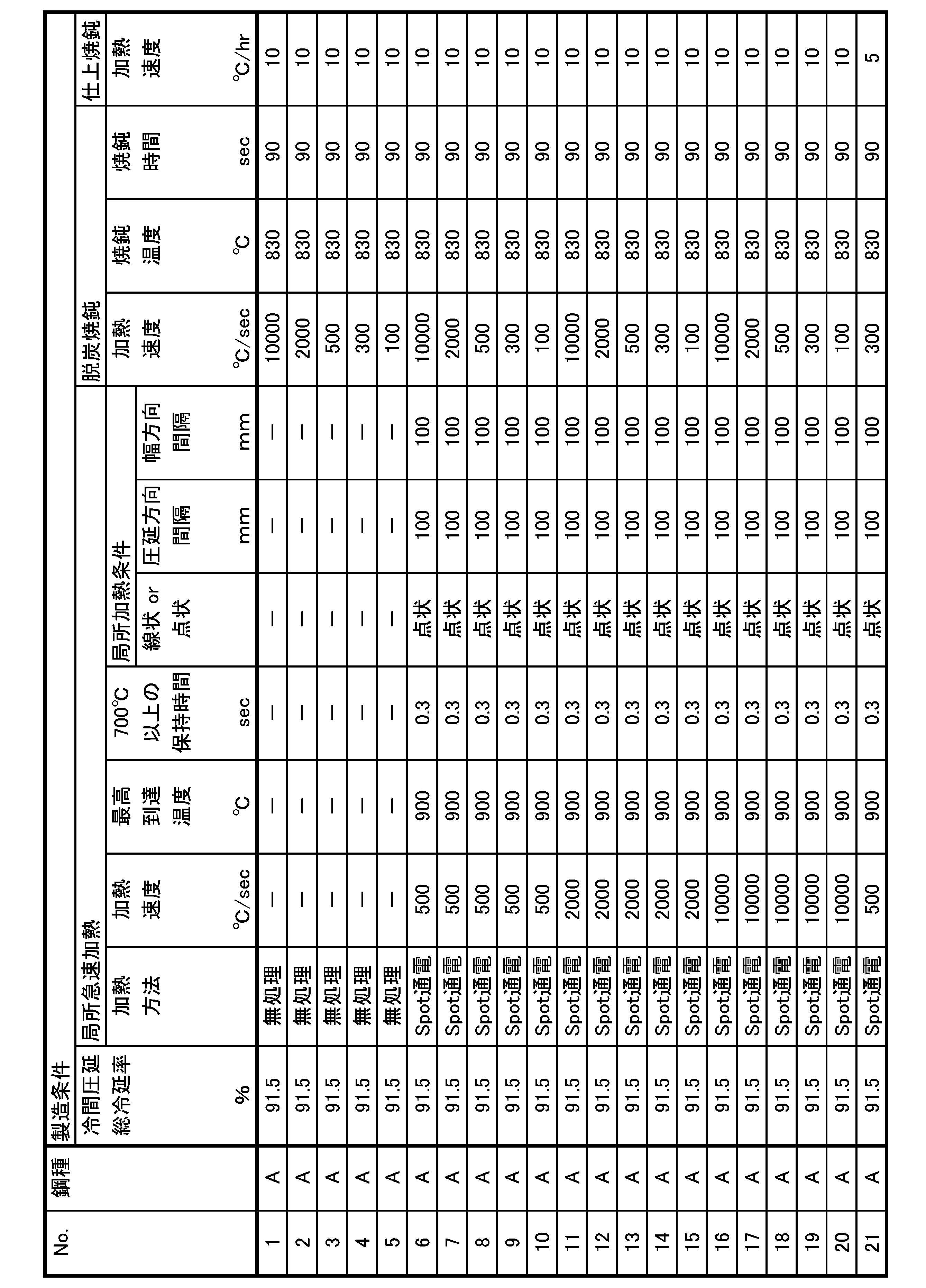
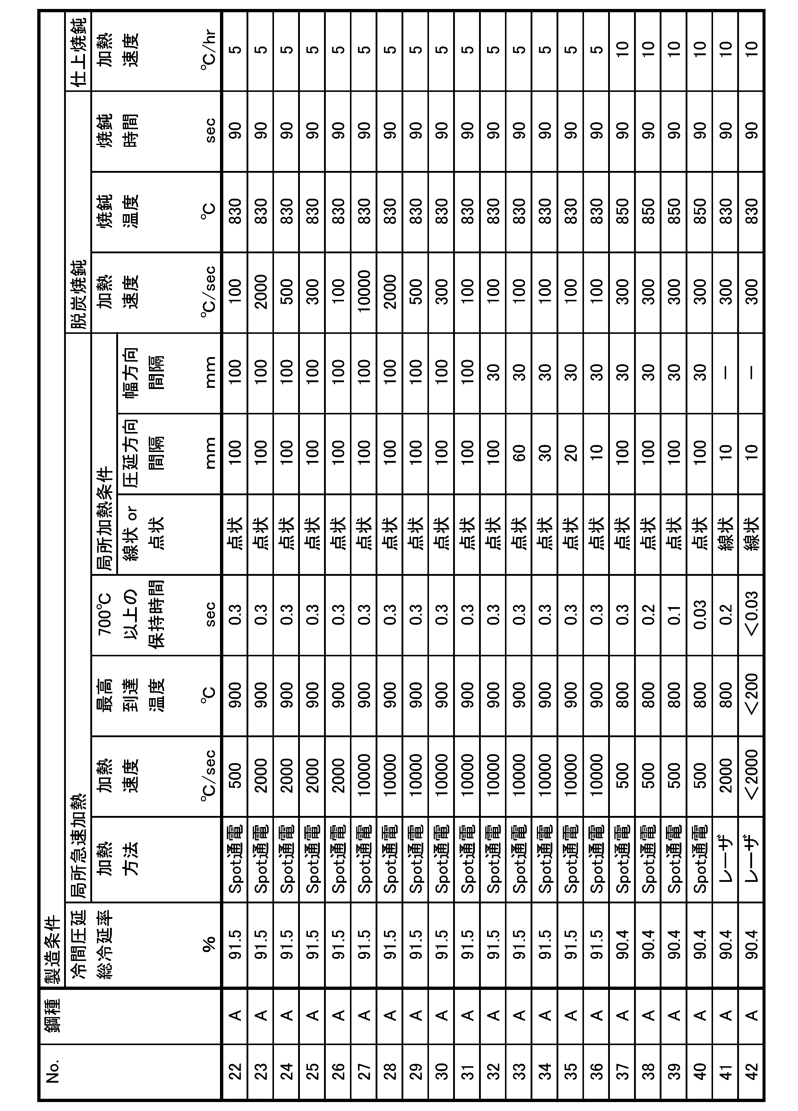

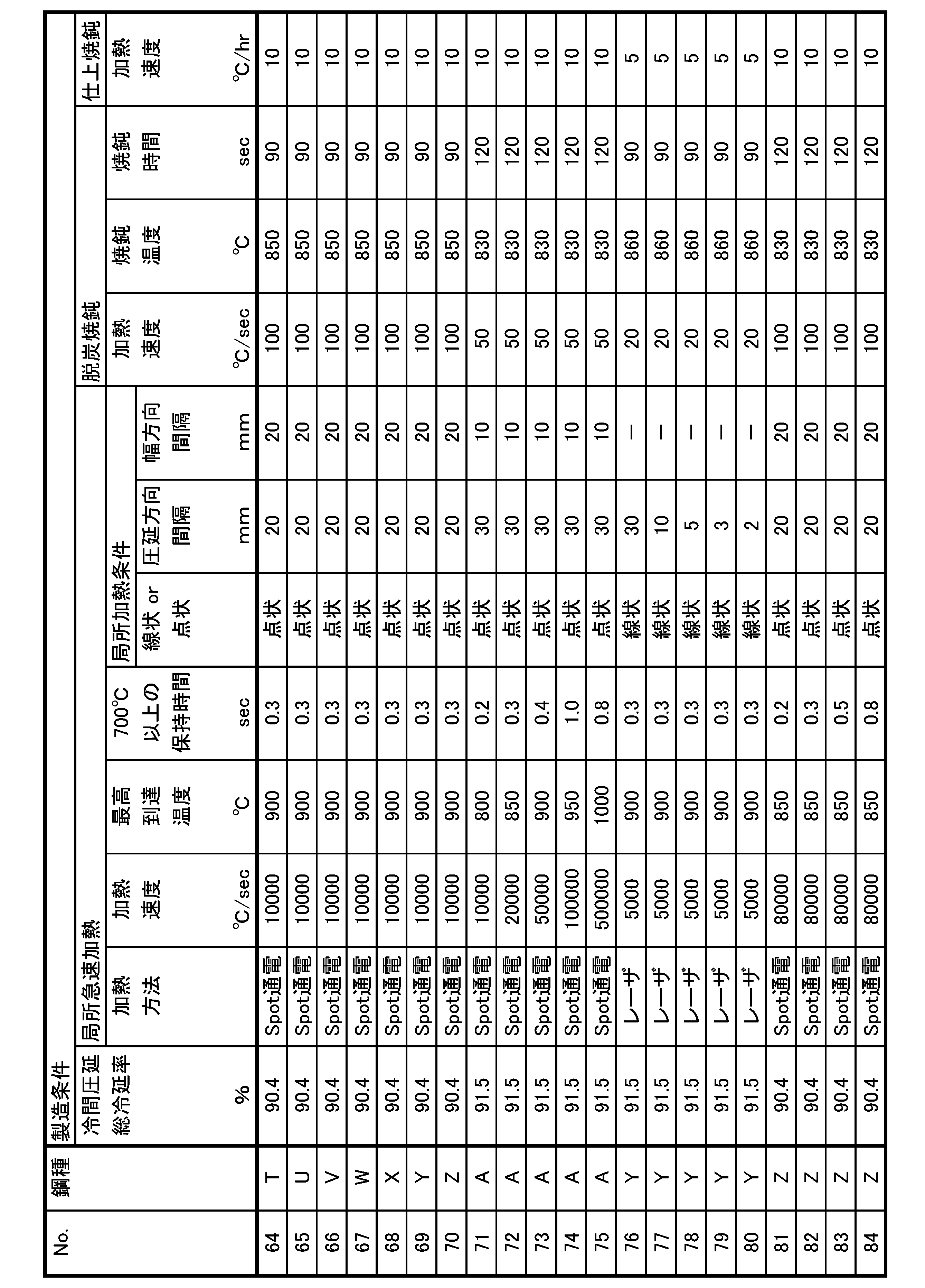
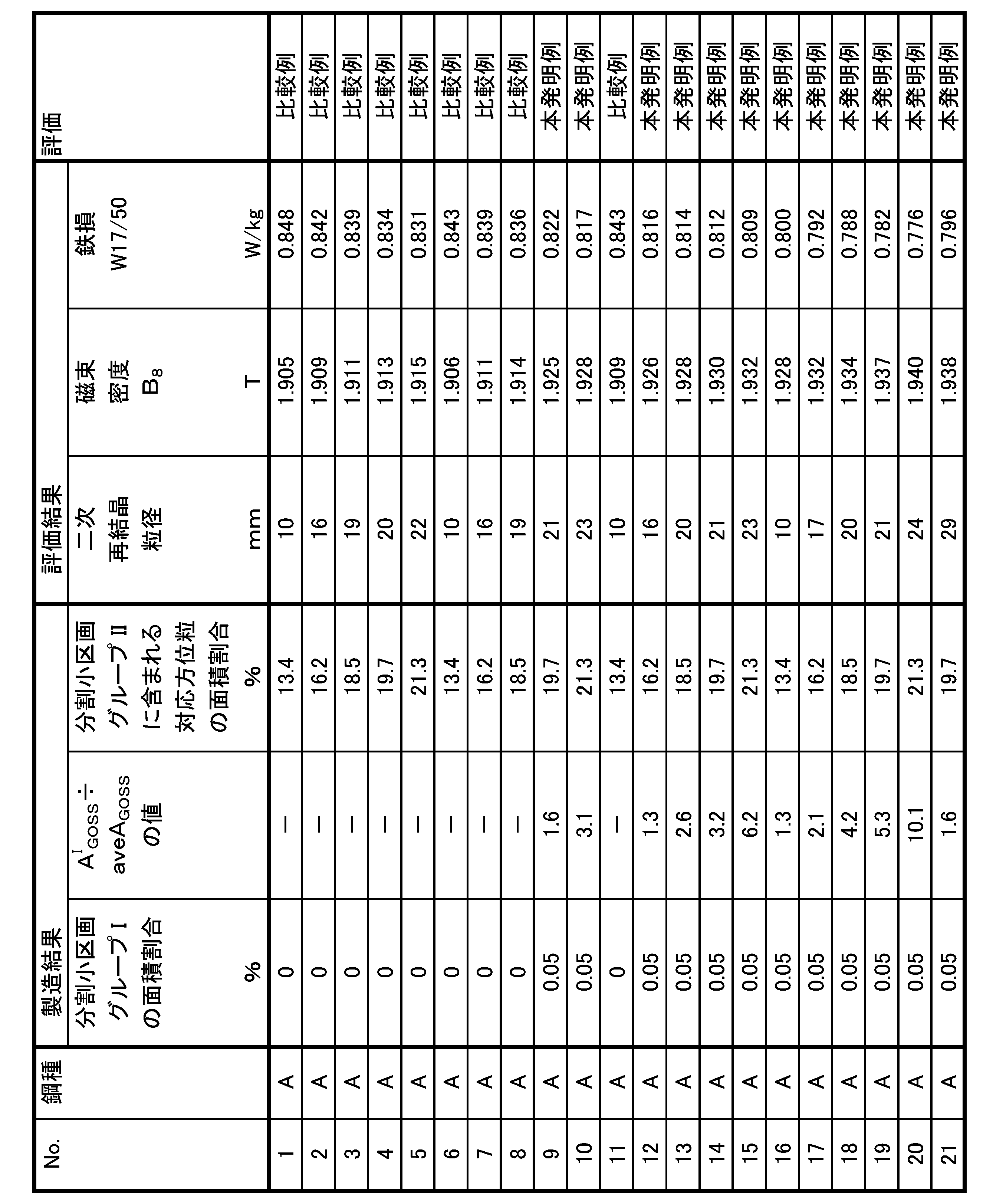


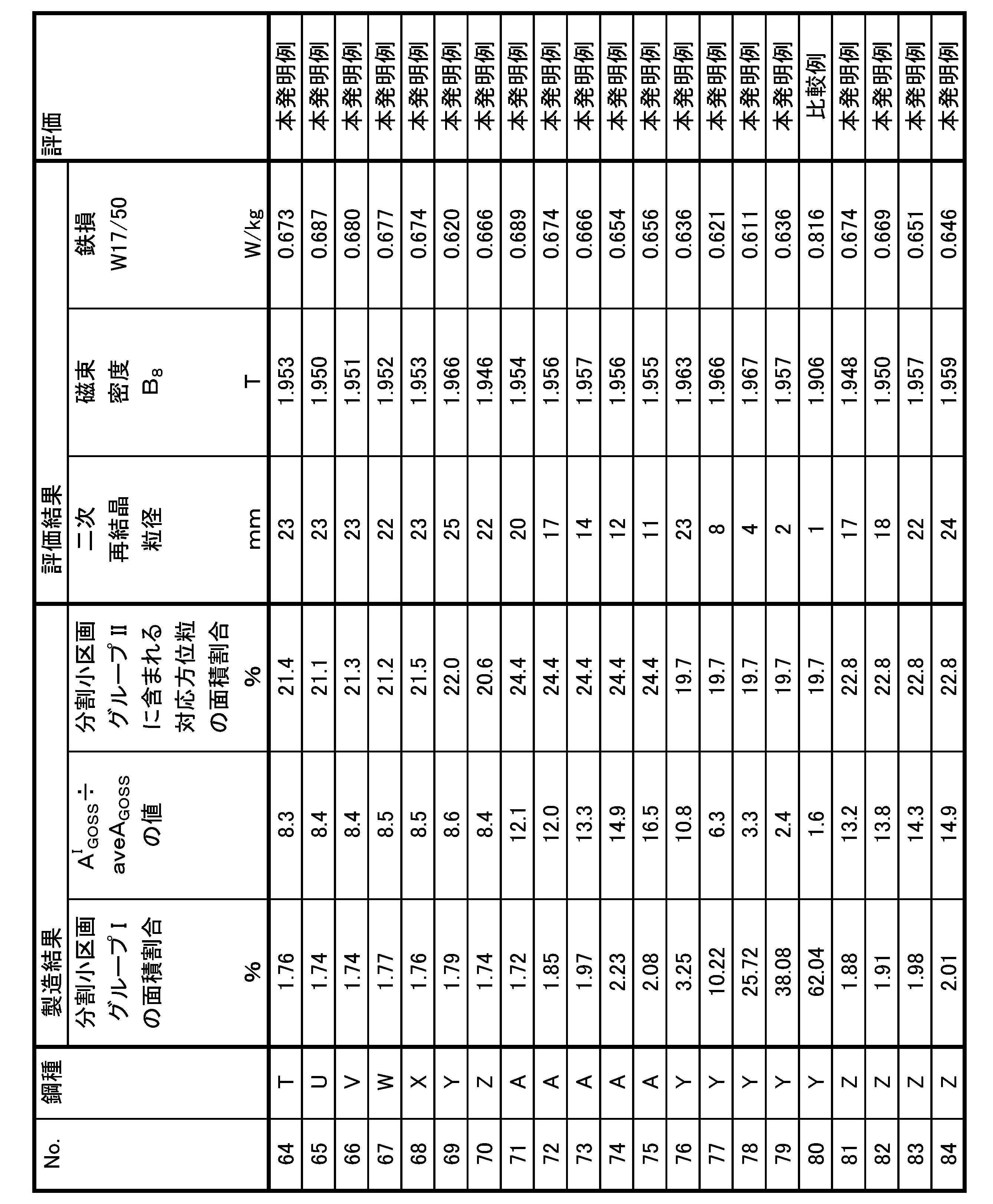
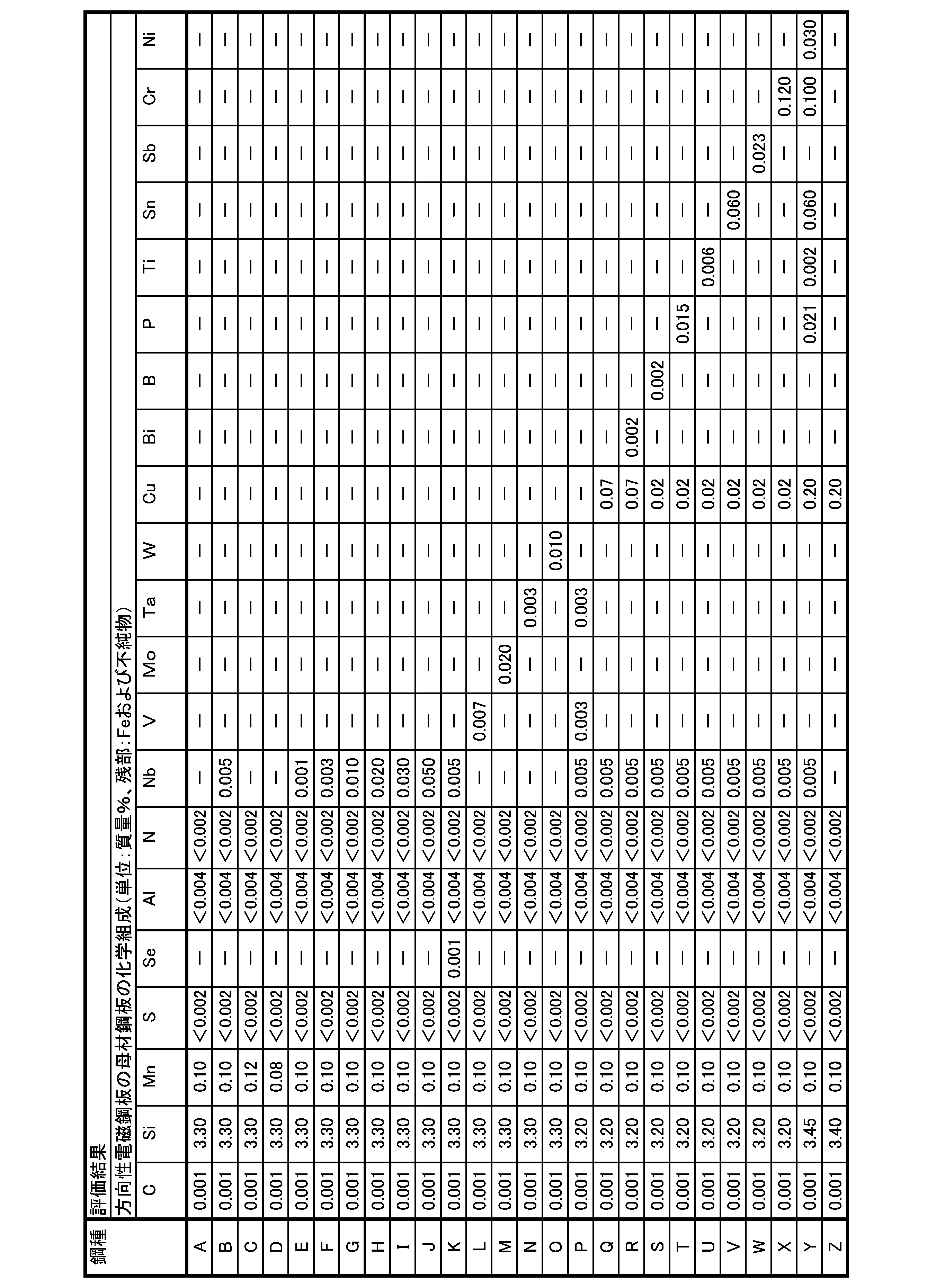
2 局所加熱影響領域
3 局所加熱非影響領域(マトリックス部)
4 局所加熱領域境界
5 局所加熱影響領域境界
14 ゴス方位粒
15 粗大ゴス方位粒
21 圧延方向
22 幅方向(圧延直角方向)
Claims (2)
- 方向性電磁鋼板用の脱炭焼鈍鋼板であって、
板面上の少なくとも100mm×100mmの領域を分割区画と定義し、前記分割区画内を1mm×1mmの領域に細分して各区画を分割小区画と定義し、
前記分割区画内に含まれる結晶粒の平均粒径を単位μmでaveDと定義し、
1つの分割小区画内に含まれる結晶粒数に対してこの分割小区画内に含まれる粒径が3.0×aveD以上となる結晶粒数の個数割合をFCと定義し、前記分割区画内に含まれる結晶粒数に対して前記分割区画内に含まれる粒径が3.0×aveD以上となる結晶粒数の個数割合をaveFCと定義し、
FC÷aveFCの値が1.3以上となる分割小区画を合わせて分割小区画グループIと定義したとき、
前記分割区画の面積に対して前記分割小区画グループIの面積割合が0.05%以上50%以下であり、且つ
圧延面法線方向を回転軸とする理想ゴス方位からのずれ角をαと定義し、
圧延直角方向を回転軸とする理想ゴス方位からのずれ角をβと定義し、
板面上の測定点で測定する結晶方位のずれ角を(α β)と表し、
前記測定点での角度偏差をφ=(α2+β2)1/2と定義し、
前記角度偏差φが10°以下である結晶粒をゴス方位粒と定義し、
前記分割小区画グループIの面積に対して前記分割小区画グループI内に含まれるゴス方位粒の面積割合をAI GOSSと定義し、前記分割区画の面積に対して前記分割区画内に含まれるゴス方位粒の面積割合をaveAGOSSと定義したとき、
AI GOSS÷aveAGOSSの値が1.3以上である
ことを特徴とする方向性電磁鋼板用の脱炭焼鈍鋼板。 - 理想ゴス方位に対してΣ9対応方位関係にある結晶方位からの方位差が10°以内である結晶粒を対応方位粒と定義し、
前記分割区画のうちで前記分割小区画グループIを除く分割小区画を分割小区画グループIIと定義したとき、
前記分割小区画グループIIの面積に対して前記分割小区画グループII内に含まれる対応方位粒の面積割合が10%以上50%以下である
ことを特徴とする請求項1に記載の方向性電磁鋼板用の脱炭焼鈍鋼板。
Priority Applications (4)
| Application Number | Priority Date | Filing Date | Title |
|---|---|---|---|
| KR1020267000179A KR20260019612A (ko) | 2023-06-29 | 2024-06-27 | 방향성 전자 강판용 탈탄 어닐링 강판 |
| EP24832024.4A EP4737604A1 (en) | 2023-06-29 | 2024-06-27 | Decarburized annealed steel sheet for grain-oriented electromagnetic steel sheet |
| CN202480042482.9A CN121399284A (zh) | 2023-06-29 | 2024-06-27 | 方向性电磁钢板用的脱碳退火钢板 |
| JP2025516099A JP7787485B2 (ja) | 2023-06-29 | 2024-06-27 | 方向性電磁鋼板用の脱炭焼鈍鋼板 |
Applications Claiming Priority (2)
| Application Number | Priority Date | Filing Date | Title |
|---|---|---|---|
| JP2023106859 | 2023-06-29 | ||
| JP2023-106859 | 2023-06-29 |
Publications (1)
| Publication Number | Publication Date |
|---|---|
| WO2025005165A1 true WO2025005165A1 (ja) | 2025-01-02 |
Family
ID=93939095
Family Applications (1)
| Application Number | Title | Priority Date | Filing Date |
|---|---|---|---|
| PCT/JP2024/023278 Ceased WO2025005165A1 (ja) | 2023-06-29 | 2024-06-27 | 方向性電磁鋼板用の脱炭焼鈍鋼板 |
Country Status (5)
| Country | Link |
|---|---|
| EP (1) | EP4737604A1 (ja) |
| JP (1) | JP7787485B2 (ja) |
| KR (1) | KR20260019612A (ja) |
| CN (1) | CN121399284A (ja) |
| WO (1) | WO2025005165A1 (ja) |
Citations (9)
| Publication number | Priority date | Publication date | Assignee | Title |
|---|---|---|---|---|
| JPH10183312A (ja) * | 1996-10-21 | 1998-07-14 | Kawasaki Steel Corp | 鉄損が低く、耐歪特性および実機特性に優れた方向性電磁鋼板およびその製造方法 |
| JPH10183313A (ja) * | 1996-10-21 | 1998-07-14 | Kawasaki Steel Corp | 鉄損が低く、耐歪特性および実機特性に優れた方向性電磁鋼板 |
| JP2001060505A (ja) * | 1999-08-20 | 2001-03-06 | Kawasaki Steel Corp | 一方向性電磁鋼板用の一次再結晶焼鈍板 |
| JP2002212637A (ja) * | 2001-01-12 | 2002-07-31 | Nippon Steel Corp | 磁束密度の高い鏡面方向性電磁鋼板の製造方法 |
| JP2007169762A (ja) | 2005-12-26 | 2007-07-05 | Jfe Steel Kk | 低鉄損方向性電磁鋼板の製造方法 |
| WO2012014290A1 (ja) | 2010-07-28 | 2012-02-02 | 新日本製鐵株式会社 | 方向性電磁鋼板及びその製造方法 |
| JP2020164907A (ja) * | 2019-03-28 | 2020-10-08 | Jfeスチール株式会社 | 方向性電磁鋼板の製造方法 |
| JP2022161269A (ja) | 2021-04-08 | 2022-10-21 | 日本製鉄株式会社 | 方向性電磁鋼板の製造方法 |
| JP2023106859A (ja) | 2022-01-21 | 2023-08-02 | ダイキン工業株式会社 | 冷凍装置、冷媒漏洩検知装置、および冷媒漏洩検知方法 |
-
2024
- 2024-06-27 WO PCT/JP2024/023278 patent/WO2025005165A1/ja not_active Ceased
- 2024-06-27 EP EP24832024.4A patent/EP4737604A1/en active Pending
- 2024-06-27 CN CN202480042482.9A patent/CN121399284A/zh active Pending
- 2024-06-27 KR KR1020267000179A patent/KR20260019612A/ko active Pending
- 2024-06-27 JP JP2025516099A patent/JP7787485B2/ja active Active
Patent Citations (9)
| Publication number | Priority date | Publication date | Assignee | Title |
|---|---|---|---|---|
| JPH10183312A (ja) * | 1996-10-21 | 1998-07-14 | Kawasaki Steel Corp | 鉄損が低く、耐歪特性および実機特性に優れた方向性電磁鋼板およびその製造方法 |
| JPH10183313A (ja) * | 1996-10-21 | 1998-07-14 | Kawasaki Steel Corp | 鉄損が低く、耐歪特性および実機特性に優れた方向性電磁鋼板 |
| JP2001060505A (ja) * | 1999-08-20 | 2001-03-06 | Kawasaki Steel Corp | 一方向性電磁鋼板用の一次再結晶焼鈍板 |
| JP2002212637A (ja) * | 2001-01-12 | 2002-07-31 | Nippon Steel Corp | 磁束密度の高い鏡面方向性電磁鋼板の製造方法 |
| JP2007169762A (ja) | 2005-12-26 | 2007-07-05 | Jfe Steel Kk | 低鉄損方向性電磁鋼板の製造方法 |
| WO2012014290A1 (ja) | 2010-07-28 | 2012-02-02 | 新日本製鐵株式会社 | 方向性電磁鋼板及びその製造方法 |
| JP2020164907A (ja) * | 2019-03-28 | 2020-10-08 | Jfeスチール株式会社 | 方向性電磁鋼板の製造方法 |
| JP2022161269A (ja) | 2021-04-08 | 2022-10-21 | 日本製鉄株式会社 | 方向性電磁鋼板の製造方法 |
| JP2023106859A (ja) | 2022-01-21 | 2023-08-02 | ダイキン工業株式会社 | 冷凍装置、冷媒漏洩検知装置、および冷媒漏洩検知方法 |
Also Published As
| Publication number | Publication date |
|---|---|
| CN121399284A (zh) | 2026-01-23 |
| JPWO2025005165A1 (ja) | 2025-01-02 |
| EP4737604A1 (en) | 2026-05-06 |
| JP7787485B2 (ja) | 2025-12-17 |
| KR20260019612A (ko) | 2026-02-10 |
Similar Documents
| Publication | Publication Date | Title |
|---|---|---|
| CN105579596B (zh) | 取向性电磁钢板的制造方法 | |
| CN104220607B (zh) | 取向性电磁钢板的制造方法 | |
| JP6844125B2 (ja) | 方向性電磁鋼板の製造方法 | |
| CN111417737B (zh) | 低铁损取向性电磁钢板及其制造方法 | |
| JP7644338B2 (ja) | 方向性電磁鋼板の製造方法 | |
| JP6160649B2 (ja) | 方向性電磁鋼板の製造方法 | |
| JP7606155B1 (ja) | 方向性電磁鋼板 | |
| WO2018117671A1 (ko) | 방향성 전기강판의 제조방법 | |
| JP7606154B1 (ja) | 方向性電磁鋼板 | |
| US20240035128A1 (en) | Grain-oriented electrical steel sheet, and manufacturing method therefor | |
| MX2012015155A (es) | Metodo para la produccion de chapa de acero magnetica de grano orientado. | |
| JP2008063655A (ja) | 板幅方向にわたり安定して磁気特性が得られる方向性電磁鋼板の製造方法 | |
| JP7644339B2 (ja) | 方向性電磁鋼板の製造方法 | |
| CN107406936A (zh) | 取向性电磁钢板及其制造方法 | |
| JP7787485B2 (ja) | 方向性電磁鋼板用の脱炭焼鈍鋼板 | |
| JP3551849B2 (ja) | 一方向性電磁鋼板用の一次再結晶焼鈍板 | |
| WO2025005169A1 (ja) | 冷延鋼板 | |
| US20250051867A1 (en) | Grain oriented electrical steel sheet and method for manufacturing same | |
| JP7538460B1 (ja) | 鉄損特性に優れた方向性電磁鋼板 | |
| WO2025005170A1 (ja) | 方向性電磁鋼板 | |
| WO2024154774A1 (ja) | 方向性電磁鋼板の製造方法 | |
| CN120345043A (zh) | 卷绕铁芯 | |
| WO2025187777A1 (ja) | 脱炭焼鈍鋼板 |
Legal Events
| Date | Code | Title | Description |
|---|---|---|---|
| 121 | Ep: the epo has been informed by wipo that ep was designated in this application |
Ref document number: 24832024 Country of ref document: EP Kind code of ref document: A1 |
|
| WWE | Wipo information: entry into national phase |
Ref document number: 2025516099 Country of ref document: JP |
|
| WWE | Wipo information: entry into national phase |
Ref document number: 202517128121 Country of ref document: IN |
|
| ENP | Entry into the national phase |
Ref document number: 1020267000179 Country of ref document: KR Free format text: ST27 STATUS EVENT CODE: A-0-1-A10-A15-NAP-PA0105 (AS PROVIDED BY THE NATIONAL OFFICE) |
|
| WWE | Wipo information: entry into national phase |
Ref document number: 1020267000179 Country of ref document: KR |
|
| REG | Reference to national code |
Ref country code: BR Ref legal event code: B01A Ref document number: 112025028991 Country of ref document: BR |
|
| WWP | Wipo information: published in national office |
Ref document number: 202517128121 Country of ref document: IN |
|
| WWE | Wipo information: entry into national phase |
Ref document number: 2024832024 Country of ref document: EP Ref document number: 2026100506 Country of ref document: RU |
|
| NENP | Non-entry into the national phase |
Ref country code: DE |
|
| ENP | Entry into the national phase |
Ref document number: 2024832024 Country of ref document: EP Effective date: 20260129 |
|
| ENP | Entry into the national phase |
Ref document number: 2024832024 Country of ref document: EP Effective date: 20260129 |
|
| WWP | Wipo information: published in national office |
Ref document number: 1020267000179 Country of ref document: KR |
|
| WWP | Wipo information: published in national office |
Ref document number: 2026100506 Country of ref document: RU |
|
| WWP | Wipo information: published in national office |
Ref document number: 2024832024 Country of ref document: EP |