WO2025005072A1 - 押圧ユニットおよびばね部材 - Google Patents
押圧ユニットおよびばね部材 Download PDFInfo
- Publication number
- WO2025005072A1 WO2025005072A1 PCT/JP2024/022940 JP2024022940W WO2025005072A1 WO 2025005072 A1 WO2025005072 A1 WO 2025005072A1 JP 2024022940 W JP2024022940 W JP 2024022940W WO 2025005072 A1 WO2025005072 A1 WO 2025005072A1
- Authority
- WO
- WIPO (PCT)
- Prior art keywords
- spring
- pressed body
- spring member
- portions
- connection
- Prior art date
- Legal status (The legal status is an assumption and is not a legal conclusion. Google has not performed a legal analysis and makes no representation as to the accuracy of the status listed.)
- Ceased
Links
Images





Classifications
-
- F—MECHANICAL ENGINEERING; LIGHTING; HEATING; WEAPONS; BLASTING
- F16—ENGINEERING ELEMENTS AND UNITS; GENERAL MEASURES FOR PRODUCING AND MAINTAINING EFFECTIVE FUNCTIONING OF MACHINES OR INSTALLATIONS; THERMAL INSULATION IN GENERAL
- F16F—SPRINGS; SHOCK-ABSORBERS; MEANS FOR DAMPING VIBRATION
- F16F1/00—Springs
- F16F1/02—Springs made of steel or other material having low internal friction; Wound, torsion, leaf, cup, ring or the like springs, the material of the spring not being relevant
- F16F1/18—Leaf springs
Definitions
- the present invention relates to a pressing unit and a spring member.
- a spring member is known that is placed between a first pressed body and a second pressed body and applies pressure to one or both of them.
- Spring members are used in a variety of devices.
- a spring member fixes a power element to a heat dissipation fin that dissipates heat generated in the power element to the outside (see, for example, Patent Document 1).
- the spring member described in Patent Document 1 is a plate-shaped member that has a bent portion and a cut-and-raised portion, and the cut-and-raised portion presses against the power element to apply a load.
- the bent portion of this spring member is inserted into a hole in a clamp and fixed to the clamp. At this time, the clamp is fixed to the heat dissipation fin.
- Patent Document 1 when the spring member disclosed in Patent Document 1 is configured so that the pressing unit is assembled by sliding the second pressed body relative to the first pressed body, there is a risk that the spring member may become misaligned relative to the pressing metal fitting when the second pressed body slides. If the contact position of the raised part relative to the power element becomes misaligned, the load applied to the power element may change, and the power element may not be properly fixed relative to the heat dissipation fin.
- the present invention has been made in consideration of the above, and aims to provide a pressing unit and spring member that can reliably and stably press a second pressed body against a first pressed body in a configuration in which a second pressed body is slid and assembled relative to a first pressed body.
- the pressing unit of the present invention comprises a first pressed body having an open end and a bottomed cylindrical shape at the other end, a second pressed body housed in the first pressed body, and a spring member disposed between the first pressed body and the second pressed body and applying pressure to the first pressed body and the second pressed body, the spring member having a band-shaped first spring portion curved in an arc from one end to the other end, a band-shaped second spring portion curved in an arc from one end to the other end, one end of which is located closer to the other end side of the first spring portion than one end of the first spring portion, and a connecting portion connecting the first spring portion and the second spring portion, and one end of the first spring portion is provided with a fixing portion that is fixed to the opening side of the first pressed body.
- the pressing unit according to the present invention is characterized in that the direction from one end to the other end of the first and second spring parts is aligned with the direction from the opening in the first pressed body to the bottom.
- the spring member according to the present invention is characterized in that it comprises a first pressed body having an opening at one end and a bottomed cylindrical shape with a bottom at the other end, a second pressed body housed in the first pressed body, and a spring member that is disposed between the first pressed body and the second pressed body and applies pressure to the first pressed body and the second pressed body, the spring member having a band-like first spring portion curved in an arc from one end to the other end, a band-like second spring portion curved in an arc from one end to the other end, one end of which is located closer to the other end side of the first spring portion than one end of the first spring portion, and a connecting portion that connects the first spring portion and the second spring portion, and a fixing portion that is fixed to the opening of the first pressed body is provided at one end of the first spring portion.
- the spring member according to the present invention is characterized in that, in the above invention, the first spring portion and the second spring portion are connected by the connecting portion with the convex directions due to the curvature aligned.
- the spring member according to the present invention is characterized in that, in the above invention, it has two of the first spring parts, and the connection part has a first connection part that connects one of the first spring parts to the second spring part, and a second connection part that connects the other of the first spring parts to the second spring part.
- the spring member according to the present invention is characterized in that it comprises a plurality of the second spring portions and a plurality of connection portions that respectively connect the first spring portion to each of the second spring portions.
- the spring member according to the present invention is characterized in that, in the above invention, it further comprises a plurality of the first spring portions, and the plurality of connection portions respectively connect each of the first spring portions to each of the second spring portions.
- the spring member according to the present invention is further characterized in that it further comprises a tongue portion extending from the end of the connection portion on the side that connects to the first spring portion.
- the spring member according to the present invention is characterized in that, in the above invention, the first and second spring parts each have a band-shaped main body part curved in an arc in the longitudinal direction, a first end part extending from one end of the main body part and curved in a manner opposite to the curved manner of the main body part, and a second end part extending from an end of the main body part opposite to the side to which the first end part extends and curved in a manner opposite to the curved manner of the main body part, and the connection part is connected to the main body part.
- the spring member according to the present invention is characterized in that, in the above invention, the main body has a flat portion extending in a flat plate shape, a first connecting portion that curves and extends from one end of the flat portion and connects to the first end, and a second connecting portion that curves and extends from the other end of the flat portion and connects to the second end, and the connecting portion is connected to the flat portion.
- the present invention has the advantage that, in a configuration in which a second pressed body is slid and assembled onto a first pressed body, the second pressed body can be reliably and stably pressed against the first pressed body.
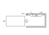
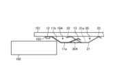
- FIG. 1 is a side view showing a schematic diagram of a pressing unit using a spring member according to a first embodiment of the present invention.
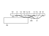
- FIG. 2 is a diagram for explaining the assembly of the pressing unit.
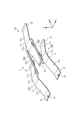
- FIG. 3 is a perspective view (part 1) showing the configuration of the spring member according to the first embodiment of the present invention.
- FIG. 4 is a second perspective view showing the configuration of the spring member according to the first embodiment of the present invention.
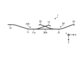
- FIG. 5 is a side view taken along the direction of the arrow A in FIG.
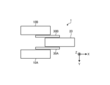
- FIG. 6 is a plan view showing a configuration of the spring member according to the first embodiment of the present invention.
- FIG. 7 is a diagram (part 1) for explaining the behavior of the spring member when the pressing unit according to the first embodiment of the present invention is assembled.
- FIG. 1 is a side view showing a schematic diagram of a pressing unit using a spring member according to a first embodiment of the present invention.
- FIG. 2 is a diagram for explaining the assembly of the pressing unit.
- FIG. 8 is a second diagram for explaining the behavior of the spring member when the pressing unit according to the first embodiment of the present invention is assembled.
- FIG. 9 is a third diagram for explaining the behavior of the spring member when the pressing unit according to the first embodiment of the present invention is assembled.
- FIG. 10 is a perspective view (part 1) showing a configuration of a spring member according to a first modification of the first embodiment of the present invention.
- FIG. 11 is a second perspective view showing the configuration of the spring member according to the first modification of the first embodiment of the present invention.
- FIG. 12 is a perspective view (part 1) showing a configuration of a spring member according to the second modification of the first embodiment of the present invention.
- FIG. 13 is a second perspective view showing a configuration of a spring member according to the second modification of the first embodiment of the present invention.
- FIG. 14 is a plan view showing a configuration of a spring member according to a third modification of the first embodiment of the present invention.
- FIG. 15 is a plan view showing a configuration of a spring member according to the fourth modification of the first embodiment of the present invention.
- FIG. 16 is a plan view showing a configuration of a spring member according to a fifth modification of the first embodiment of the present invention.
- FIG. 17 is a perspective view showing a configuration of a spring member according to the second embodiment of the present invention.
- (Embodiment 1) 1 is a side view showing a pressing unit using a spring member according to a first embodiment of the present invention.
- the pressing unit 100 according to the first embodiment of the present invention has a spring member 1 disposed between a first pressed body 101 and a second pressed body 102.
- the spring member 1 applies pressure to both the first pressed body 101 and the second pressed body 102 by elastic force.
- the first pressed body 101 is in the form of a bottomed cylinder having an open end and a bottom at the other end.
- the first pressed body 101 shown in Fig. 1 is in the form of a bottomed hollow prism having an open left side in the figure.
- the second pressed body 102 has a rectangular column shape and is housed within the first pressed body 101 .
- FIG. 2 is a diagram for explaining the assembly of the pressing unit.
- the pressing unit 100 is assembled by sliding and inserting the second pressed body 102 into the first pressed body 101.
- Figures 3 and 4 are perspective views showing the configuration of the spring member according to the first embodiment of the present invention.
- Figure 5 is a side view in the direction of the arrow A in Figure 4.
- Figure 6 is a plan view showing the configuration of the spring member according to the first embodiment of the present invention. Note that Figure 6 is a simplified schematic view of the spring member, and omits through holes 14, which will be described later.
- the X, Y, and Z directions are mutually orthogonal.
- the X direction is the extension direction (longitudinal direction) of the spring portion
- the Y direction is the width direction
- the Z direction is the height direction.
- the spring member 1 is formed using flat spring steel made of metal, resin, etc.
- the spring member 1 is formed by punching out the outer shape of the spring member 1 from flat spring steel and partially curving it.
- the spring member 1 comprises two first spring portions (first spring portions 10A, 10B), one second spring portion 20, a first connection portion 30A that connects the first spring portion 10A and the second spring portion 20, and a second connection portion 30B that connects the first spring portion 10B and the second spring portion 20.
- the first spring parts 10A and 10B each have a band-shaped main body part 11 curved in an arc in the longitudinal direction, a first end part 12 extending from one end of the main body part 11 and curved in a manner opposite to the curved manner of the main body part 11, and a second end part 13 extending from the end of the main body part 11 opposite the side to which the first end part 12 extends and curved in a manner opposite to the curved manner of the main body part 11.
- the main body 11 has a flat portion 11a extending in a flat plate shape, a first connecting portion 11b extending in a curved manner from one end of the flat portion 11a and connecting to the first end portion 12, and a second connecting portion 11c extending in a curved manner from the other end of the flat portion 11a and connecting to the second end portion 13.
- the first connecting portion 11b and the second connecting portion 12b are curved on the same side with respect to the flat portion 11a.
- a through hole 14 penetrating in the thickness direction is formed in the first end portion 12. This through hole 14 corresponds to a fixing portion.
- the first spring portions 10A and 10B are described as having the same shape and the same size, but they may have different shapes, such as curved shapes and sizes.
- the term “same shape” refers to the same shape including manufacturing errors.
- the first spring portions 10A, 10B are positioned side by side in the Y direction with the same curved shape. Specifically, the first spring portions 10A, 10B are positioned side by side in the Y direction with the direction of the convexity due to the curve being the same. In other words, they are positioned so that the top of the convexity due to the curve faces the height direction. In this case, for example, the ends of the first ends 12 of the first spring portions 10A, 10B are positioned on the same XY plane and the same YZ plane.
- the second spring portion 20 has a band-shaped main body portion 21 that is curved in an arc shape in the longitudinal direction, a first end portion 22 that extends from one end of the main body portion 21 and is curved in a manner opposite to the curved manner of the main body portion 21, and a second end portion 23 that extends from the end portion of the main body portion 21 opposite to the side from which the first end portion 22 extends and is curved in a manner opposite to the curved manner of the main body portion 21.
- the main body 21 has a flat portion 21a extending in a flat plate shape, a first connecting portion 21b extending in a curved manner from one end of the flat portion 21a and connecting to the first end 22, and a second connecting portion 21c extending in a curved manner from the other end of the flat portion 21a and connecting to the second end 23.
- the second spring portion 20 may have the same shape as the first spring portion 10A (10B), or may have a shape that is different from the first spring portion 10A (10B) in terms of curvature, size, etc.
- the second spring portion 20 is located between the first spring portions 10A, 10B in the Y direction and shifted in the X direction with respect to the first spring portions 10A, 10B. In this case, one end (first end portion 22) of the second spring portion 20 is shifted toward the second end portion 13 with respect to the first end portion 12. Moreover, the first spring portions 10A, 10B and the second spring portion 20 are arranged with the convex directions due to the curvature aligned in the height direction.
- first end 12, 22 and the second end 13, 23 may extend in a curved manner from the main body 11, 21 and then extend parallel to the flat portion 11a, 21a, or may be adjusted to an angle that is parallel to the contact surface of the first pressed body 101 when the second pressed body 102 is assembled to the first pressed body 101.
- the first connection portion 30A has one end connected to the flat portion 11a of the first spring portion 10A and the other end connected to the flat portion 21a of the second spring portion 20.
- the second connection portion 30B has one end connected to the flat portion 11a of the first spring portion 10B and the other end connected to the flat portion 21a of the second spring portion 20.
- the second connection portion 30B is connected to the opposite side of the second spring portion 20 in the width direction from the connection side of the first connection portion 30A.
- the first connection portion 30A and the second connection portion 30B extend in a direction parallel to a plane (here, the XY plane) passing through the flat portions 11a, 21a of the main body portion 11 and the main body portion 21.
- the first connection portion 30A and the second connection portion 30B are located at the end opposite the first ends 12, 22 and the second ends 13, 23 in the height direction.
- the spring member 1 is fixed inside the first pressed body 101 (see FIG. 1). Specifically, the spring member 1 is fixed to the inner wall surface of the first pressed body 101 by a bolt 103 attached to the opening side of the first pressed body 101. At this time, the shaft portion of the bolt 103 passes through the through hole 14, and the first end portion 12 is sandwiched and fixed between the head portion and the first pressed body 101.
- the extension direction of the first spring portions 10A, 10B and the second spring portion 20 is substantially the same as the direction from the opening toward the bottom (see FIG. 2).
- Figure 2 shows an example in which the second end 13, the first end 22, and the second end 23 are in contact with the first pressed body 101, but it is sufficient that at least the first end 12 fixed by bolt 103 is in contact with the first pressed body 101, and the load can be adjusted depending on the contact state of each end.
- Figs. 7 to 9 are diagrams for explaining the behavior of the spring member when the pressing unit according to the first embodiment of the present invention is assembled.
- the second pressed body 102 When the second pressed body 102 is inserted into the first pressed body 101, the second pressed body 102 comes into contact with the first connecting parts 11b of the first spring parts 10A and 10B (see FIG. 7). At this time, the first spring parts 10A and 10B are deformed by the contact of the second pressed body 102.
- the second pressed body 102 comes into contact with the first connection portion 30A and the second connection portion 30B (only the first connection portion 30A is shown in Figures 7 to 9) while sliding against the flat portion 11a of the main body portion 11 (see Figure 8).
- the first connection portion 30A and the second connection portion 30B are deformed by contact with the second pressed body 102.
- the change in the load received by the spring member 1 when the second pressed body 102 comes into contact with the second spring portion 20 can be reduced.
- the second pressed body 102 then comes into contact with the second spring portion 20 while sliding against the first connecting portion 30A and the second connecting portion 30B.
- the second spring portion 20 is deformed by contact with the second pressed body 102.
- the contact position with the second pressed body 102 is not limited to the above, and there may be cases where the second pressed body 102 comes into contact only with the flat portions 11a, 21a, for example.
- the spring member 1 receives a load directed toward the bottom side of the first pressed body 101 due to the sliding of the second pressed body 102, the first end 12 is fixed by the bolt 103, so that misalignment with respect to the first pressed body 101 is suppressed.
- the bolt 103 is attached to the upstream side of the sliding direction of the second pressed body 102 (the opening side of the first pressed body 101), even if a load is applied when the second pressed body 102 is inserted, the bolt 103 can be used as a fulcrum to extend in the X direction and smoothly displace in the Z direction.
- each spring portion of the spring member 1 is curved along the sliding direction of the second pressed body 102, so that when the second pressed body 102 comes into contact with the spring member 1 and slides, the second pressed body 102 can be moved smoothly.
- the spring member 1 connects the first spring portions 10A, 10B and the second spring portion 20 by a connection portion that connects the tops of the spring portions (flat portions 11a, 21a in this case) and is designed so that the second pressed body 102 comes into contact with the connection portion when inserted, thereby making it possible to reduce the change in load when the second pressed body 102 comes into contact with the second spring portion 20 after coming into contact with the first spring portions 10A, 10B.
- the second pressed body in a configuration in which the second pressed body is slid and assembled onto the first pressed body, the second pressed body can be reliably and stably pressed against the first pressed body.
- the configuration may be such that it only includes the first spring portion 10A, the first connection portion 30A, and the second spring portion 20.
- a configuration may be adopted in which there is one first spring portion and two second spring portions, i.e., the second spring portion is replaced with the first spring portion, and the first spring portion is replaced with the second spring portion.
- Figs. 10 and 11 are perspective views showing the configuration of a spring member according to the first modification of the first embodiment of the present invention.
- a third connection portion 30C that connects the first connection portion 30A and the second connection portion 30B is further provided in addition to the configuration of the spring member 1 according to the first embodiment.
- the spring member 1A in this modified example 1 includes two first spring portions (first spring portions 10A, 10B), one second spring portion 20, a first connection portion 30A that connects the first spring portion 10A and the second spring portion 20, a second connection portion 30B that connects the first spring portion 10B and the second spring portion 20, and a third connection portion 30C that connects the first connection portion 30A and the second connection portion 30B.
- the third connection portion 30C has one end which is an end of the first connection portion 30A in the extension direction (X direction) and is connected to the end of the first spring portion 10A that connects to the main body portion 11, and the other end which is an end of the second connection portion 30B in the extension direction (X direction) and is connected to the end of the first spring portion 10B that connects to the main body portion 11.
- the spring member 1A is attached to the first pressed body 101 by the bolt 103, and the pressing unit is assembled by inserting the second pressed body 102.
- the first end 12 is fixed by the bolt 103, so that misalignment with the first pressed body 101 is suppressed, and the curved shape of the spring part and the connection part allow the second pressed body 102 to be smoothly inserted.
- the first modification in a configuration in which the second pressed body is slid and assembled onto the first pressed body, the second pressed body can be reliably and stably pressed against the first pressed body.
- the first connection portion 30A and the second connection portion 30B are connected by the third connection portion 30C, so that the first spring portions 10A and 10B are prevented from separating when a load is applied to the spring member 1A, and the relative positional relationship between the first spring portions 10A and 10B can be maintained.
- Figs. 12 and 13 are perspective views showing the configuration of a spring member according to the second modification of the first embodiment of the present invention.
- the second modification includes three first spring portions and two second spring portions.
- the spring member 1B in this modified example 2 includes three first spring portions (first spring portions 10A, 10B, 10C), two second spring portions (second spring portions 20A, 20B), a first connection portion 30A connecting the first spring portion 10A to the second spring portion 20A, a second connection portion 30B connecting the first spring portion 10B to the second spring portion 20A, a third connection portion 30D connecting the first spring portion 10B to the second spring portion 20B, and a fourth connection portion 30E connecting the first spring portion 10C to the second spring portion 20B.
- the first spring portion 10C has the same shape as the first spring portions 10A and 10B.
- the second spring portions 20A and 20B have the same shape as the second spring portion 20.
- the first connection portion 30A has one end connected to the flat portion 11a of the first spring portion 10A and the other end connected to the flat portion 21a of the second spring portion 20A.
- the second connection portion 30B has one end connected to the flat portion 11a of the first spring portion 10A and the other end connected to the flat portion 21a of the second spring portion 20A.
- the second connection portion 30B is connected to the opposite side of the second spring portion 20A in the width direction from the connection side of the first connection portion 30A.
- the third connection portion 30D has one end connected to the flat portion 11a of the first spring portion 10B and the other end connected to the flat portion 21a of the second spring portion 20B.
- the fourth connection portion 30E has one end connected to the flat portion 11a of the first spring portion 10C and the other end connected to the flat portion 21a of the second spring portion 20B.
- the fourth connection portion 30E is connected to the opposite side of the width of the second spring portion 20B from the connection side of the third connection portion 30C.
- the spring member 1B is attached to the first pressed body 101 by the bolt 103, and the pressing unit is assembled by inserting the second pressed body 102.
- the first spring portion 10C, the second spring portions 20A and 20B, and the first connecting portion 30A to the fourth connecting portion 30E are deformed in the same manner as the corresponding components (the first spring portions 10A and 10B, the second spring portion 20, and the first connecting portion 30A and the second connecting portion 30B).
- the first end 12 is fixed by the bolt 103, so that misalignment with the first pressed body 101 is suppressed, and the curved shape of the spring part and the connection part allow the second pressed body 102 to be smoothly inserted.
- the first modification in a configuration in which the second pressed body is slid and assembled onto the first pressed body, the second pressed body can be reliably and stably pressed against the first pressed body.
- the second pressed body 102 can be fixed to the first pressed body 101 more uniformly and stably.
- connection part (third connection part 30C) according to the first modification and a connection part connecting the third connection part 30D and the fourth connection part 30E may be further provided.
- the positions of the second spring parts 20A and 20B in the X direction may be shifted.
- Fig. 14 is a plan view showing the configuration of a spring member according to the third modification of the first embodiment of the present invention.
- the first spring portion 10A and the first spring portion 10B are positioned offset in the X direction compared to the configuration of the spring member 1 according to the first embodiment.
- the spring member 1C in this modified example 3 includes two first spring portions (first spring portions 10A, 10B), one second spring portion 20, a first connection portion 30A that connects the first spring portion 10A and the second spring portion 20, and a second connection portion 30F that connects the first spring portion 10B and the second spring portion 20.
- first spring portion 10B is shifted toward second spring portion 20 in the X direction relative to first spring portion 10A. Therefore, in spring member 1C, first spring portion 10A protrudes on the side opposite second spring portion 20 in the X direction.
- second connection portion 30F has a shorter length in the X direction compared to first connection portion 30A.
- the spring member 1C is attached to the first pressed body 101 by the bolt 103, and the pressing unit is assembled by inserting the second pressed body 102.
- the second pressed body 102 contacts the first spring portion 10A, and then contacts the first spring portion 10B, the first connecting portion 30A, the second connecting portion 30F, and the second spring portion 20, in that order.
- the first spring portions 10A, 10B, the second spring portion 20, the first connecting portion 30A, and the second connecting portion 30F deform in the same manner as the corresponding components (the first spring portions 10A, 10B, the second spring portion 20, and the first connecting portion 30A and the second connecting portion 30B).
- the first end 12 is fixed by the bolt 103, so that misalignment with the first pressed body 101 is suppressed, and the curved shape of the spring part and the connection part allow the second pressed body 102 to be smoothly inserted.
- the third modification in a configuration in which the second pressed body is slid and assembled onto the first pressed body, the second pressed body can be reliably and stably pressed against the first pressed body.
- Fig. 15 is a plan view showing the configuration of a spring member according to the fourth modified example of the first embodiment of the present invention. Below, parts that differ from the first embodiment and the like will be described, and the same components will be given the same reference numerals and descriptions thereof will be omitted.
- the spring member 1D of the fourth modified example includes two first spring portions (first spring portions 10A, 10B), two second spring portions (second spring portions 20A, 20B), and a connection portion 30G that connects the first spring portions 10A, 10B and the second spring portions 20A, 20B.
- first spring portions and the second spring portions are arranged linearly along the X direction.
- connection portion 30G is provided between the first spring portion 10A and the first spring portion 10B and between the second spring portion 20A and the second spring portion 20B in the Y direction, with one end connected to the flat portion 11a of the first spring portion 10A, 10B, respectively, and the other end connected to the flat portion 21a of the second spring portion 20A, 20B, respectively.
- the spring member 1D is attached to the first pressed body 101 by the bolt 103, and the pressing unit is assembled by inserting the second pressed body 102. At this time, the second pressed body 102 comes into contact with the first spring parts 10A and 10B, and then comes into contact with the connection part 30G and the second spring parts 20A and 20B in that order, causing it to deform.
- the first end 12 is fixed by the bolt 103, so that misalignment with the first pressed body 101 is suppressed, and the curved shape of the spring part and the connection part allow the second pressed body 102 to be smoothly inserted.
- the fourth modification in a configuration in which the second pressed body is slid and assembled onto the first pressed body, the second pressed body can be reliably and stably pressed against the first pressed body.
- the first spring portion and the second spring portion are arranged in a straight line along the X direction, and each spring portion is connected by a single connection portion 30G. This allows the size in the Y direction to be smaller than, for example, the configuration of the spring member 1 according to the first embodiment.
- Fig. 16 is a plan view showing the configuration of a spring member according to the fifth variation of the first embodiment of the present invention. Below, parts that differ from the first embodiment and the like will be described, and the same components will be given the same reference numerals and will not be described.
- the spring member 1E in this modified example 5 includes one first spring portion 10, one second spring portion 20, and a first connecting portion 30H and a second connecting portion 30I that connect the first spring portion 10 and the second spring portion 20.
- the first spring portion 10 and the second spring portion 20 are arranged side by side in the X direction.
- the first connection portion 30H has one end connected to the flat portion 11a of the first spring portion 10 and the other end connected to the flat portion 21a of the second spring portion 20.
- the second connection portion 30I has one end connected to the flat portion 11a of the first spring portion 10 and the other end connected to the flat portion 21a of the second spring portion 20.
- the second connection portion 30I is connected to the first spring portion 10 and the second spring portion 20 on the opposite side in the width direction to the connection side of the first connection portion 30H.
- the spring member 1E is attached to the first pressed body 101 by the bolt 103, and the pressing unit is assembled by inserting the second pressed body 102. At this time, the second pressed body 102 comes into contact with the first spring portion 10, and then comes into contact with the first connecting portion 30H, the second connecting portion 30I, and the second spring portion 20 in that order, causing it to deform.
- the first end 12 is fixed by the bolt 103, so that misalignment with the first pressed body 101 is suppressed, and the curved shape of the spring part and the connection part allow the second pressed body 102 to be smoothly inserted.
- the second pressed body in a configuration in which the second pressed body is slid and assembled onto the first pressed body, the second pressed body can be reliably and stably pressed against the first pressed body.
- Fig. 17 is a perspective view showing the configuration of a spring member according to the second embodiment of the present invention.
- a tongue portion is further provided in addition to the configuration of the spring member 1 according to the first embodiment.
- the spring member 1F in this second embodiment includes two first spring portions (first spring portions 10A, 10B), one second spring portion 20, a first connection portion 30A connecting the first spring portion 10A and the second spring portion 20, a second connection portion 30B connecting the first spring portion 10B and the second spring portion 20, a first tongue portion 40A extending from the first connection portion 30A, and a second tongue portion 40B extending from the second connection portion 30B.
- the first tongue portion 40A is an end of the first connection portion 30A, and extends from the end that connects to the first spring portion 10A in the extension direction of the first spring portion 10A (here, this corresponds to the X direction).
- the first tongue portion 40A is preferably curved in the same manner as the corresponding position of the first spring portion 10A in the Y direction, and at least the tip portion forms an arc on the same side as the curved shape of the first spring portion 10A.
- the second tongue portion 40B is an end of the second connection portion 30B, and extends from the end that connects to the first spring portion 10B in the extension direction of the first spring portion 10B (corresponding to the X direction here).
- the second tongue portion 40B is preferably curved in the same manner as the corresponding position of the first spring portion 10B in the Y direction, and at least the tip portion forms an arc on the same side as the curved shape of the first spring portion 10B.
- the spring member 1F is attached to the first pressed body 101 by the bolt 103, and the pressing unit is assembled by inserting the second pressed body 102.
- the second pressed body 102 comes into contact with the first spring portion 10, and then the first tongue portion 40A and the second tongue portion 40B.
- the second pressed body 102 then comes into contact with the first connecting portion 30A and the second connecting portion 30B, and the second spring portion 20, in that order, and is deformed.
- the first end 12 is fixed by the bolt 103, so that misalignment with the first pressed body 101 is suppressed, and the curved shape of the spring part and the connection part allow the second pressed body 102 to be smoothly inserted.
- the second pressed body in a configuration in which the second pressed body is slid and assembled onto the first pressed body, the second pressed body can be reliably and stably pressed against the first pressed body.
- the spring member 1F of the second embodiment by bringing the second pressed body 102 into contact with the first tongue portion 40A and the second tongue portion 40B before the first connection portion 30A and the second connection portion 30B, the first connection portion 30A and the second connection portion 30B can be deformed more smoothly by the contact of the second pressed body 102. As a result, compared to the first embodiment, the second pressed body 102 can be assembled to the first pressed body 101 more smoothly.
- the spring constant of the first spring part may be smaller than the spring constant of the second spring part.
- the thickness of the first spring part may be made thinner than the thickness of the second spring part, the height of the spring (here, the distance in the Z direction) may be made smaller, or the inclination angle of the connecting part relative to the flat part may be made gentler.
- ribs may be provided at the connection parts.
- the strength of the connection parts can be adjusted by forming the ribs.
- the width may be gradually reduced from the connecting portion toward the end.
- the width of the spring portion toward the end By reducing the width of the spring portion toward the end, the area in which the connection portion is disposed can be increased, and the width of the connection portion can be increased, or the distance between the spring portions in the Y direction can be reduced, thereby reducing the size of the spring member in the Y direction.
- the configuration of the present invention can be applied even when there is a limit to the size of the installation location in the Y direction, and more spring members can be disposed in the Y direction.
- the width may be gradually increased from the connecting portion toward the end portion.
- connection portion between the ends in the X direction may be bent so as to be convex in the Z direction in the opposite direction to the curved shape (convex direction) of the spring portion.
- This bending of the connection portion allows the second spring portion to come into contact with the second pressed body before the connection portion, resulting in a significant increase in insertion resistance and allowing the position of the second pressed body relative to the first pressed body to be easily grasped.
- first and second spring portions may be increased in the X and Y directions as appropriate, and the number of connection portions may be increased accordingly.
- the first spring portion is described as having a second end portion and a second connecting portion, but the first spring portion may be configured without the second end portion and the second connecting portion.
- the spring member 1 is fixed to the first pressed body 101 by inserting the bolt 103 into the through hole 14 formed in the first end portion 12, but the fixing is not limited to the through hole 14, and may be configured to be fixed by, for example, welding or the like.
- the welded portion (melt mark) formed by welding corresponds to the fixed portion.
- the present invention may include various embodiments not described here, and various design changes may be made without departing from the technical ideas defined by the claims.
- the pressing unit and spring member of the present invention are suitable for reliably and stably pressing the second pressed body against the first pressed body in a configuration in which the second pressed body is slid and assembled relative to the first pressed body.
Landscapes
- Engineering & Computer Science (AREA)
- General Engineering & Computer Science (AREA)
- Mechanical Engineering (AREA)
- Springs (AREA)
Abstract
本発明に係る押圧ユニットは、一端が開口し、他端に底部を有する有底筒状をなす第1の被押圧体と、第1の被押圧体に収容される第2の被押圧体と、第1の被押圧体と第2の被押圧体との間に配置され、第1および第2の被押圧体に対して圧力を加えるばね部材と、を備え、ばね部材は、一端から他端にかけて弧状に湾曲してなる帯状の第1ばね部と、一端から他端にかけて弧状に湾曲してなる帯状をなし、該一端が、第1ばね部の一端よりも該第1ばね部の他端側に位置する第2ばね部と、第1および第2ばね部を接続する接続部と、を有し、第1ばね部の一端には、第1の被押圧体の開口側に固定される固定部が設けられる。
Description
本発明は、押圧ユニットおよびばね部材に関する。
第1の被押圧体と第2の被押圧体との間に設置され、その一方もしくは双方を加圧するばね部材が知られている。ばね部材は、様々な装置に用いられている。例えば、ばね部材は、パワー素子を、該パワー素子において発生した熱を外部に放出するための放熱フィンに固定する(例えば、特許文献1を参照)。特許文献1に記載のばね部材は、板状の部材に曲げ部および切り起こし部が設けられ、切り起こし部がパワー素子に圧接して荷重を加える。また、このばね部材は、曲げ部を、押え金具の穴に挿入して該押え金具に固定される。この際、押え金具は、放熱フィンに固定される。
しかしながら、特許文献1が開示するばね部材は、押圧ユニットが第1の被押圧体に対して第2の被押圧体をスライドさせて組み付ける構成の場合、第2の被押圧体のスライド時に、押え金具に対してばね部材がずれるおそれがあった。パワー素子に対する切り起こし部の接触位置がずれると、パワー素子に加える荷重が変わるなどして、放熱フィンに対してパワー素子を適切に固定することができない場合があった。
本発明は、上記に鑑みてなされたものであって、第1の被押圧体に対して第2の被押圧体をスライドして組み付ける構成において、第1の被押圧体に対し、第2の被押圧体を確実かつ安定して押圧することができる押圧ユニットおよびばね部材を提供することを目的とする。
上述した課題を解決し、目的を達成するために、本発明にかかる押圧ユニットは、一端が開口し、他端に底部を有する有底筒状をなす第1の被押圧体と、前記第1の被押圧体に収容される第2の被押圧体と、前記第1の被押圧体と前記第2の被押圧体との間に配置され、前記第1の被押圧体および前記第2の被押圧体に対して圧力を加えるばね部材と、を備え、前記ばね部材は、一端から他端にかけて弧状に湾曲してなる帯状の第1ばね部と、一端から他端にかけて弧状に湾曲してなる帯状をなし、該一端が、前記第1ばね部の一端よりも該第1ばね部の他端側に位置する第2ばね部と、前記第1ばね部および前記第2ばね部を接続する接続部と、を有し、前記第1ばね部の一端には、前記第1の被押圧体の開口側に固定される固定部が設けられる、ことを特徴とする。
また、本発明に係る押圧ユニットは、上記発明において、前記第1および第2ばね部は、一端から他端に向かう方向が、前記第1の被押圧体における前記開口から前記底部に向かう方向に沿う、ことを特徴とする。
また、本発明に係るばね部材は、一端が開口し、他端に底部を有する有底筒状をなす第1の被押圧体と、前記第1の被押圧体に収容される第2の被押圧体と、前記第1の被押圧体と前記第2の被押圧体との間に配置され、前記第1の被押圧体および前記第2の被押圧体に対して圧力を加えるばね部材であって、一端から他端にかけて弧状に湾曲してなる帯状の第1ばね部と、一端から他端にかけて弧状に湾曲してなる帯状をなし、該一端が、前記第1ばね部の一端よりも該第1ばね部の他端側に位置する第2ばね部と、前記第1ばね部および前記第2ばね部を接続する接続部と、を有し、前記第1ばね部の一端には、前記第1の被押圧体の開口に固定される固定部が設けられる、ことを特徴とする。
また、本発明に係るばね部材は、上記発明において、前記第1ばね部と、前記第2ばね部とは、湾曲による凸の向きを揃えて前記接続部によって接続される、ことを特徴とする。
また、本発明に係るばね部材は、上記発明において、二つの前記第1ばね部を備え、前記接続部は、一方の第1ばね部と前記第2ばね部とを接続する第1接続部と、他方の第1ばね部と前記第2ばね部とを接続する第2接続部と、を有することを特徴とする。
また、本発明に係るばね部材は、上記発明において、複数の前記第2ばね部と、前記第1ばね部と各第2ばね部とをそれぞれ接続する複数の接続部と、を備えることを特徴とする。
また、本発明に係るばね部材は、上記発明において、複数の前記第1ばね部、をさらに備え、前記複数の接続部は、各第1ばね部と各第2ばね部とをそれぞれ接続することを特徴とする。
また、本発明に係るばね部材は、上記発明において、前記接続部の前記第1ばね部に接続する側の端部から延びる舌片部、をさらに備えることを特徴とする。
また、本発明に係るばね部材は、上記発明において、前記第1および第2ばね部は、長手方向を弧状に湾曲させた帯状の本体部と、前記本体部の一端から延び、該本体部の湾曲態様とは逆の態様で湾曲してなる第1端部と、前記本体部の前記第1端部が延びる側とは反対側の端部から延び、該本体部の湾曲態様とは逆の態様で湾曲してなる第2端部と、をそれぞれ有し、前記接続部は、前記本体部に接続する、ことを特徴とする。
また、本発明に係るばね部材は、上記発明において、前記本体部は、平板状に延びる平坦部と、前記平坦部の一端から湾曲して延びるとともに、前記第1端部に連結する第1連結部と、前記平坦部の他端から湾曲して延びるとともに、前記第2端部に連結する第2連結部と、を有し、前記接続部は、前記平坦部に接続する、ことを特徴とする。
本発明によれば、第1の被押圧体に対して第2の被押圧体をスライドして組み付ける構成において、第1の被押圧体に対し、第2の被押圧体を確実かつ安定して押圧することができるという効果を奏する。
以下の説明では、本発明を実施するための形態(以下、「実施の形態」という)として、ばね部材を用いた押圧ユニットについて説明する。また、この実施の形態により、この発明が限定されるものではない。さらに、図面の記載において、同一部分には同一の符号を付している。さらにまた、図面は、模式的なものであり、各部材の厚みと幅との関係、各部材の比率等は、現実と異なることに留意する必要がある。また、図面の相互間においても、互いの寸法や比率が異なる部分が含まれている。
(実施の形態1)
図1は、本発明の実施の形態1にかかるばね部材を用いた押圧ユニットを模式的に示す側面図である。本発明の実施の形態1にかかる押圧ユニット100は、第1の被押圧体101と第2の被押圧体102との間にばね部材1を配置する。ばね部材1は、弾性力により、第1の被押圧体101と第2の被押圧体102の双方に対して圧力を加える。
図1は、本発明の実施の形態1にかかるばね部材を用いた押圧ユニットを模式的に示す側面図である。本発明の実施の形態1にかかる押圧ユニット100は、第1の被押圧体101と第2の被押圧体102との間にばね部材1を配置する。ばね部材1は、弾性力により、第1の被押圧体101と第2の被押圧体102の双方に対して圧力を加える。
第1の被押圧体101は、一端が開口し、他端に底部を有する有底筒状をなす。図1に示す第1の被押圧体101は、図の左側が開口する有底の中空角柱状をなしている。
第2の被押圧体102は、角柱状をなして、第1の被押圧体101内に収容される。
第2の被押圧体102は、角柱状をなして、第1の被押圧体101内に収容される。
図2は、押圧ユニットの組付けを説明するための図である。押圧ユニット100は、第1の被押圧体101に対して、第2の被押圧体102をスライドさせて挿入させることによって組み付けられる。
図3および図4は、本発明の実施の形態1にかかるばね部材の構成を示す斜視図である。図5は、図4の矢視A方向の側面図である。図6は、本発明の実施の形態1にかかるばね部材の構成を示す平面図である。なお、図6は、ばね部材を簡略化して模式的に示すものであり、後述する貫通孔14等を省略した図である。以下の図において、X方向、Y方向およびZ方向は、互いに直交する。また、以下の説明において、X方向をばね部の延伸方向(長手方向)、Y方向を幅方向、Z方向を高さ方向として説明する。
ばね部材1は、金属、樹脂などからなる平板状のばね鋼を用いて形成される。例えば、ばね部材1は、平板状のばね鋼に対して、ばね部材1の外形を打ち抜き、部分的に湾曲させることによって形成される。
ばね部材1は、二つの第1ばね部(第1ばね部10A、10B)と、一つの第2ばね部20と、第1ばね部10Aおよび第2ばね部20を接続する第1接続部30Aと、第1ばね部10Bおよび第2ばね部20を接続する第2接続部30Bとを備える。
第1ばね部10A、10Bは、長手方向を弧状に湾曲させた帯状の本体部11と、本体部11の一端から延び、該本体部11の湾曲態様とは逆の態様で湾曲してなる第1端部12と、本体部11の第1端部12が延びる側とは反対側の端部から延び、該本体部11の湾曲態様とは逆の態様で湾曲してなる第2端部13とをそれぞれ有する。
本体部11は、平板状に延びる平坦部11aと、平坦部11aの一端から湾曲して延びるとともに、第1端部12に連結する第1連結部11bと、平坦部11aの他端から湾曲して延びるとともに、第2端部13に連結する第2連結部11cとを有する。第1連結部11bおよび第2連結部12bは、平坦部11aに対して同じ側に湾曲する。
また、第1端部12には、厚さ方向に貫通する貫通孔14が形成される。この貫通孔14は、固定部に相当する。
なお、本実施の形態1において、第1ばね部10A、10Bは、同じ形状かつ同じ大きさであるものとして説明するが、湾曲態様や大きさ等が互いに異なる形状であってもよい。ここで、形状が「同じ」とは、製造上の誤差等を含んで同じものを指す。
また、第1端部12には、厚さ方向に貫通する貫通孔14が形成される。この貫通孔14は、固定部に相当する。
なお、本実施の形態1において、第1ばね部10A、10Bは、同じ形状かつ同じ大きさであるものとして説明するが、湾曲態様や大きさ等が互いに異なる形状であってもよい。ここで、形状が「同じ」とは、製造上の誤差等を含んで同じものを指す。
第1ばね部10A、10Bは、湾曲態様を揃えてY方向に並んで位置する。具体的には、第1ばね部10A、10Bは、湾曲による凸の向きを揃えてY方向に並べられてなる。すなわち、湾曲によって凸の頭頂が高さ方向に向くように並べられる。この際、例えば、第1ばね部10A、10Bにおいて、各第1端部12の端部は、同一のXY平面上かつ同一のYZ平面上に位置する。
第2ばね部20は、長手方向を弧状に湾曲させた帯状の本体部21と、本体部21の一端から延び、該本体部21の湾曲態様とは逆の態様で湾曲してなる第1端部22と、本体部21の第1端部22が延びる側とは反対側の端部から延び、該本体部21の湾曲態様とは逆の態様で湾曲してなる第2端部23とを有する。
本体部21は、平板状に延びる平坦部21aと、平坦部21aの一端から湾曲して延びるとともに、第1端部22に連結する第1連結部21bと、平坦部21aの他端から湾曲して延びるとともに、第2端部23に連結する第2連結部21cとを有する。
第2ばね部20は、第1ばね部10A(10B)と同じ形状であってもよいし、湾曲態様や大きさ等が互いに異なる形状であってもよい。
第2ばね部20は、第1ばね部10A(10B)と同じ形状であってもよいし、湾曲態様や大きさ等が互いに異なる形状であってもよい。
第2ばね部20は、Y方向において第1ばね部10A、10Bの間、かつ、第1ばね部10A、10Bに対し、X方向にずれて位置する。この際、第2ばね部20の一端(第1端部22)は、第1端部12に対し、第2端部13側にずれている。
また、第1ばね部10A、10Bおよび第2ばね部20は、湾曲による凸の向きを高さ方向に揃えて並べられてなる。
また、第1ばね部10A、10Bおよび第2ばね部20は、湾曲による凸の向きを高さ方向に揃えて並べられてなる。
ここで、第1端部12、22および第2端部13、23は、本体部11、21から湾曲して延びた後、平坦部11a、21aと平行に延びてもよいし、第1の被押圧体101に第2の被押圧体102が組付けられた際に、第1の被押圧体101の接触面に対して平行となる角度等に調整してもよい。
第1接続部30Aは、一端が第1ばね部10Aの平坦部11aに接続するとともに、他端が第2ばね部20の平坦部21aに接続する。
第2接続部30Bは、一端が第1ばね部10Bの平坦部11aに接続するとともに、他端が第2ばね部20の平坦部21aに接続する。第2接続部30Bは、第2ばね部20の幅方向において第1接続部30Aの接続側とは反対側に接続する。
第1接続部30Aおよび第2接続部30Bは、本体部11および本体部21の平坦部11a、21aを通過する平面(ここではXY平面)と平行な方向に延びる。すなわち、第1接続部30Aおよび第2接続部30Bは、高さ方向において、第1端部12、22および第2端部13、23とは反対側の端部に位置する。
押圧ユニット100において、ばね部材1は、第1の被押圧体101の内部に固定される(図1参照)。具体的には、ばね部材1は、第1の被押圧体101の開口側に取り付けられるボルト103によって第1の被押圧体101の内部壁面に固着される。この際、ボルト103は、軸部が貫通孔14を通過し、頭部と第1の被押圧体101とによって第1端部12を挟み込んで固定する。また、第1ばね部10A、10Bおよび第2ばね部20の延伸方向は、開口から底部に向かう方向と略同じである(図2参照)。
なお、図2では、第2端部13や、第1端部22、第2端部23が第1の被押圧体101に接触している例を示しているが、少なくともボルト103によって固定されている第1端部12が第1の被押圧体101に接触していればよく、各端部の接触態様によって荷重を調整することができる。
なお、図2では、第2端部13や、第1端部22、第2端部23が第1の被押圧体101に接触している例を示しているが、少なくともボルト103によって固定されている第1端部12が第1の被押圧体101に接触していればよく、各端部の接触態様によって荷重を調整することができる。
続いて、押圧ユニットの組付け時におけるばね部材の挙動について、図7~図9を参照して説明する。図7~図9は、本発明の実施の形態1にかかる押圧ユニットの組付け時におけるばね部材の挙動を説明するための図である。
第2の被押圧体102を第1の被押圧体101に挿入すると、第2の被押圧体102は、第1ばね部10A、10Bの第1連結部11bにそれぞれ当接する(図7参照)。この際、第1ばね部10A、10Bは、第2の被押圧体102の接触によって変形する。
その後、第2の被押圧体102は、本体部11の平坦部11aに対して摺動しつつ、第1接続部30Aおよび第2接続部30B(図7~図9では第1接続部30Aのみ図示)に接触する(図8参照)。第1接続部30Aおよび第2接続部30Bは、第2の被押圧体102との接触によって変形する。第2の被押圧体102が第1接続部30Aおよび第2接続部30Bと接触することによって、第2の被押圧体102が第2ばね部20に接触する際にばね部材1が受ける荷重の変化を小さくすることができる。
そして、第2の被押圧体102は、第1接続部30Aおよび第2接続部30Bに対し摺動しつつ、第2ばね部20に接触する。第2ばね部20は、第2の被押圧体102との接触によって変形する。第2の被押圧体102の第1の被押圧体101への組付けが完了すると(図1参照)、第2の被押圧体102は、平坦部11a、21aおよび接続部と接触する。なお、ばね部材1の変形態様によって、第2の被押圧体102との接触位置は上記の限りではなく、例えば平坦部11a、21aのみと接触する場合等があり得る。
この組付け時、ばね部材1が、第2の被押圧体102のスライドによって第1の被押圧体101の底部側に向かう荷重を受けた場合、ボルト103によって第1端部12が固定されているため、第1の被押圧体101に対する位置ずれが抑制される。この際、ボルト103が、第2の被押圧体102のスライド方向の上流側(第1の被押圧体101の開口側)に取り付けられているため、第2の被押圧体102の挿入時に荷重が加わったとしても、当該ボルト103を支点として、X方向に延伸しながらZ方向に円滑に変位することができる。
また、ばね部材1は、各ばね部が、それぞれ、第2の被押圧体102のスライド方向に沿って湾曲した形状をなしているため、第2の被押圧体102がばね部材1に接触して摺動する際に、第2の被押圧体102を円滑に移動させることができる。
さらに、ばね部材1は、第1ばね部10A、10Bと第2ばね部20とを、互いの頭頂部(ここでは平坦部11a、21a)同士を接続する接続部によって接続し、第2の被押圧体102の挿入時に、第2の被押圧体102が接続部に接触するようにしたので、第2の被押圧体102が第1ばね部10A、10Bと接触した後に第2ばね部20と接触する際の荷重の変化を小さくすることができる。
上述した実施の形態1によれば、第1の被押圧体に対して第2の被押圧体をスライドして組み付ける構成において、第1の被押圧体に対し、第2の被押圧体を確実かつ安定して押圧することができる。
なお、上述した実施の形態1において、第1ばね部10A、第1接続部30A、第2ばね部20のみの構成としてもよい。
また、上述した実施の形態1において、第1ばね部を1つ、第2ばね部を2つ、すなわち第2ばね部を第1ばね部に置換し、第1ばね部を第2ばね部に置換した構成としてもよい。
(実施の形態1の変形例1)
次に、本実施の形態1の変形例1について、図10および図11を参照して説明する。図10および図11は、本発明の実施の形態1の変形例1にかかるばね部材の構成を示す斜視図である。本変形例1では、実施の形態1にかかるばね部材1の構成に対し、第1接続部30Aおよび第2接続部30Bを接続する第3接続部30Cをさらに備える。以下、実施の形態1とは異なる部分について説明し、同じ構成要素については同一の符号を付し、説明は省略する。
次に、本実施の形態1の変形例1について、図10および図11を参照して説明する。図10および図11は、本発明の実施の形態1の変形例1にかかるばね部材の構成を示す斜視図である。本変形例1では、実施の形態1にかかるばね部材1の構成に対し、第1接続部30Aおよび第2接続部30Bを接続する第3接続部30Cをさらに備える。以下、実施の形態1とは異なる部分について説明し、同じ構成要素については同一の符号を付し、説明は省略する。
本変形例1にかかるばね部材1Aは、二つの第1ばね部(第1ばね部10A、10B)と、一つの第2ばね部20と、第1ばね部10Aおよび第2ばね部20を接続する第1接続部30Aと、第1ばね部10Bおよび第2ばね部20を接続する第2接続部30Bと、第1接続部30Aおよび第2接続部30Bを接続する第3接続部30Cとを備える。
第3接続部30Cは、一端が第1接続部30Aの延伸方向(X方向)の端部であって、第1ばね部10Aの本体部11に接続する側の端部に接続するとともに、他端が第2接続部30Bの延伸方向(X方向)の端部であって、第1ばね部10Bの本体部11に接続する側の端部に接続する。
ばね部材1Aは、実施の形態1にかかるばね部材1と同様に、ボルト103によって第1の被押圧体101に取り付けられ、第2の被押圧体102の挿入によって押圧ユニットが組付けられる。
上述した本変形例1では、実施の形態1と同様に、ボルト103によって第1端部12が固定されているため、第1の被押圧体101に対する位置ずれが抑制され、ばね部の湾曲形状および接続部によって第2の被押圧体102を円滑に挿入させることができる。本変形例1によれば、第1の被押圧体に対して第2の被押圧体をスライドして組み付ける構成において、第1の被押圧体に対し、第2の被押圧体を確実かつ安定して押圧することができる。
また、変形例1にかかるばね部材1Aによれば、第3接続部30Cによって第1接続部30Aおよび第2接続部30Bが接続されているため、ばね部材1Aに荷重が加わった際の第1ばね部10A、10Bの離間を抑制し、第1ばね部10A、10Bの相対的な位置関係を維持することができる。
(実施の形態1の変形例2)
次に、本実施の形態1の変形例2について、図12および図13を参照して説明する。図12および図13は、本発明の実施の形態1の変形例2にかかるばね部材の構成を示す斜視図である。本変形例2では、三つの第1ばね部と、二つの第2ばね部とを備える。以下、実施の形態1とは異なる部分について説明し、同じ構成要素については同一の符号を付し、説明は省略する。
次に、本実施の形態1の変形例2について、図12および図13を参照して説明する。図12および図13は、本発明の実施の形態1の変形例2にかかるばね部材の構成を示す斜視図である。本変形例2では、三つの第1ばね部と、二つの第2ばね部とを備える。以下、実施の形態1とは異なる部分について説明し、同じ構成要素については同一の符号を付し、説明は省略する。
本変形例2にかかるばね部材1Bは、三つの第1ばね部(第1ばね部10A、10B、10C)と、二つの第2ばね部(第2ばね部20A、20B)と、第1ばね部10Aおよび第2ばね部20Aを接続する第1接続部30Aと、第1ばね部10Bおよび第2ばね部20Aを接続する第2接続部30Bと、第1ばね部10Bおよび第2ばね部20Bを接続する第3接続部30Dと、第1ばね部10Cおよび第2ばね部20Bを接続する第4接続部30Eと、を備える。
第1ばね部10Cは、第1ばね部10A、10Bと同じ形状をなす。
第2ばね部20A、20Bは、第2ばね部20と同じ形状をなす。
第2ばね部20A、20Bは、第2ばね部20と同じ形状をなす。
第1接続部30Aは、一端が第1ばね部10Aの平坦部11aに接続するとともに、他端が第2ばね部20Aの平坦部21aに接続する。
第2接続部30Bは、一端が第1ばね部10Aの平坦部11aに接続するとともに、他端が第2ばね部20Aの平坦部21aに接続する。第2接続部30Bは、第2ばね部20Aの幅方向において第1接続部30Aの接続側とは反対側に接続する。
第3接続部30Dは、一端が第1ばね部10Bの平坦部11aに接続するとともに、他端が第2ばね部20Bの平坦部21aに接続する。
第4接続部30Eは、一端が第1ばね部10Cの平坦部11aに接続するとともに、他端が第2ばね部20Bの平坦部21aに接続する。第4接続部30Eは、第2ばね部20Bの幅方向において第3接続部30Cの接続側とは反対側に接続する。
ばね部材1Bは、実施の形態1にかかるばね部材1と同様に、ボルト103によって第1の被押圧体101に取り付けられ、第2の被押圧体102の挿入によって押圧ユニットが組付けられる。この際、第1ばね部10C、第2ばね部20A、20B、および、第1接続部30A~第4接続部30Eは、対応する構成要素(第1ばね部10A、10B、第2ばね部20、ならびに、第1接続部30Aおよび第2接続部30B)と同様に変形する。
上述した本変形例2では、実施の形態1と同様に、ボルト103によって第1端部12が固定されているため、第1の被押圧体101に対する位置ずれが抑制され、ばね部の湾曲形状および接続部によって第2の被押圧体102を円滑に挿入させることができる。本変形例1によれば、第1の被押圧体に対して第2の被押圧体をスライドして組み付ける構成において、第1の被押圧体に対し、第2の被押圧体を確実かつ安定して押圧することができる。
また、変形例2によれば、実施の形態1にかかるばね部材1と比して、ばね部を多くしているため、より均一に安定して第2の被押圧体102を第1の被押圧体101に固定することができる。
なお、変形例2において、変形例1にかかる接続部(第3接続部30C)や、第3接続部30Dおよび第4接続部30Eを接続する接続部をさらに設けてもよい。
また、変形例2において、第2ばね部20A、20BのX方向の位置をずらした構成としてもよい。
(実施の形態1の変形例3)
次に、本実施の形態1の変形例3について、図14を参照して説明する。図14は、本発明の実施の形態1の変形例3にかかるばね部材の構成を示す平面図である。本変形例3では、実施の形態1にかかるばね部材1の構成に対し、第1ばね部10Aと、第1ばね部10Bとが、X方向にずれて位置する。以下、実施の形態1等とは異なる部分について説明し、同じ構成要素については同一の符号を付し、説明は省略する。
次に、本実施の形態1の変形例3について、図14を参照して説明する。図14は、本発明の実施の形態1の変形例3にかかるばね部材の構成を示す平面図である。本変形例3では、実施の形態1にかかるばね部材1の構成に対し、第1ばね部10Aと、第1ばね部10Bとが、X方向にずれて位置する。以下、実施の形態1等とは異なる部分について説明し、同じ構成要素については同一の符号を付し、説明は省略する。
本変形例3にかかるばね部材1Cは、二つの第1ばね部(第1ばね部10A、10B)と、一つの第2ばね部20と、第1ばね部10Aおよび第2ばね部20を接続する第1接続部30Aと、第1ばね部10Bおよび第2ばね部20を接続する第2接続部30Fとを備える。
ばね部材1Cにおいて、第1ばね部10Bは、第1ばね部10Aに対し、X方向において第2ばね部20側にずれている。このため、ばね部材1Cは、X方向において第2ばね部20側と反対側において、第1ばね部10Aが突出する。また、第2接続部30Fは、第1接続部30Aと比して、X方向の長さが短くなっている。
ばね部材1Cは、実施の形態1にかかるばね部材1と同様に、ボルト103によって第1の被押圧体101に取り付けられ、第2の被押圧体102の挿入によって押圧ユニットが組付けられる。この際、第2の被押圧体102は、第1ばね部10Aに接触した後、第1ばね部10B、第1接続部30A、第2接続部30F、第2ばね部20の順で接触する。また、第1ばね部10A、10B、第2ばね部20、第1接続部30Aおよび第2接続部30Fは、対応する構成要素(第1ばね部10A、10B、第2ばね部20、ならびに、第1接続部30Aおよび第2接続部30B)と同様に変形する。
上述した本変形例3では、実施の形態1と同様に、ボルト103によって第1端部12が固定されているため、第1の被押圧体101に対する位置ずれが抑制され、ばね部の湾曲形状および接続部によって第2の被押圧体102を円滑に挿入させることができる。本変形例3によれば、第1の被押圧体に対して第2の被押圧体をスライドして組み付ける構成において、第1の被押圧体に対し、第2の被押圧体を確実かつ安定して押圧することができる。
(実施の形態1の変形例4)
次に、本実施の形態1の変形例4について、図15を参照して説明する。図15は、本発明の実施の形態1の変形例4にかかるばね部材の構成を示す平面図である。以下、実施の形態1等とは異なる部分について説明し、同じ構成要素については同一の符号を付し、説明は省略する。
次に、本実施の形態1の変形例4について、図15を参照して説明する。図15は、本発明の実施の形態1の変形例4にかかるばね部材の構成を示す平面図である。以下、実施の形態1等とは異なる部分について説明し、同じ構成要素については同一の符号を付し、説明は省略する。
本変形例4にかかるばね部材1Dは、二つの第1ばね部(第1ばね部10A、10B)と、二つの第2ばね部(第2ばね部20A、20B)と、第1ばね部10A、10Bおよび第2ばね部20A、20Bを接続する接続部30Gとを備える。ばね部材1Dでは、第1ばね部および第2ばね部が、X方向に沿って直線状に配設されている。
接続部30Gは、Y方向において第1ばね部10Aおよび第1ばね部10Bの間、かつ第2ばね部20Aおよび第2ばね部20Bの間に設けられ、一端が第1ばね部10A、10Bの平坦部11aにそれぞれ接続するとともに、他端が第2ばね部20A、20Bの平坦部21aにそれぞれ接続する。
ばね部材1Dは、実施の形態1にかかるばね部材1と同様に、ボルト103によって第1の被押圧体101に取り付けられ、第2の被押圧体102の挿入によって押圧ユニットが組付けられる。この際、第2の被押圧体102は、第1ばね部10A、10Bに接触した後、接続部30G、第2ばね部20A、20Bの順で接触して変形する。
上述した本変形例4では、実施の形態1と同様に、ボルト103によって第1端部12が固定されているため、第1の被押圧体101に対する位置ずれが抑制され、ばね部の湾曲形状および接続部によって第2の被押圧体102を円滑に挿入させることができる。本変形例4によれば、第1の被押圧体に対して第2の被押圧体をスライドして組み付ける構成において、第1の被押圧体に対し、第2の被押圧体を確実かつ安定して押圧することができる。
上述した本変形例4によれば、第1ばね部および第2ばね部がX方向に沿って直線状に配設されており、また、一つの接続部30Gによって各ばね部を接続する構成としているため、例えば実施の形態1に係るばね部材1の構成と比して、Y方向のサイズを小さくすることができる。
(実施の形態1の変形例5)
次に、本実施の形態1の変形例5について、図16を参照して説明する。図16は、本発明の実施の形態1の変形例5にかかるばね部材の構成を示す平面図である。以下、実施の形態1等とは異なる部分について説明し、同じ構成要素については同一の符号を付し、説明は省略する。
次に、本実施の形態1の変形例5について、図16を参照して説明する。図16は、本発明の実施の形態1の変形例5にかかるばね部材の構成を示す平面図である。以下、実施の形態1等とは異なる部分について説明し、同じ構成要素については同一の符号を付し、説明は省略する。
本変形例5にかかるばね部材1Eは、一つの第1ばね部10と、一つの第2ばね部20と、第1ばね部10および第2ばね部20を接続する第1接続部30Hおよび第2接続部30Iとを備える。
第1ばね部10および第2ばね部20は、X方向に並べて設けられる。
第1接続部30Hは、一端が第1ばね部10の平坦部11aに接続するとともに、他端が第2ばね部20の平坦部21aに接続する。
第2接続部30Iは、一端が第1ばね部10の平坦部11aに接続するとともに、他端が第2ばね部20の平坦部21aに接続する。第2接続部30Iは、第1ばね部10および第2ばね部20の幅方向において第1接続部30Hの接続側とは反対側にそれぞれ接続する。
ばね部材1Eは、実施の形態1にかかるばね部材1と同様に、ボルト103によって第1の被押圧体101に取り付けられ、第2の被押圧体102の挿入によって押圧ユニットが組付けられる。この際、第2の被押圧体102は、第1ばね部10に接触した後、第1接続部30Hおよび第2接続部30I、第2ばね部20の順で接触して変形する。
上述した本変形例5では、実施の形態1と同様に、ボルト103によって第1端部12が固定されているため、第1の被押圧体101に対する位置ずれが抑制され、ばね部の湾曲形状および接続部によって第2の被押圧体102を円滑に挿入させることができる。本変形例5によれば、第1の被押圧体に対して第2の被押圧体をスライドして組み付ける構成において、第1の被押圧体に対し、第2の被押圧体を確実かつ安定して押圧することができる。
(実施の形態2)
次に、本実施の形態2について、図17を参照して説明する。図17は、本発明の実施の形態2にかかるばね部材の構成を示す斜視図である。本実施の形態2では、実施の形態1にかかるばね部材1の構成に対し、舌片部をさらに備える。以下、実施の形態1とは異なる部分について説明し、同じ構成要素については同一の符号を付し、説明は省略する。
次に、本実施の形態2について、図17を参照して説明する。図17は、本発明の実施の形態2にかかるばね部材の構成を示す斜視図である。本実施の形態2では、実施の形態1にかかるばね部材1の構成に対し、舌片部をさらに備える。以下、実施の形態1とは異なる部分について説明し、同じ構成要素については同一の符号を付し、説明は省略する。
本実施の形態2にかかるばね部材1Fは、二つの第1ばね部(第1ばね部10A、10B)と、一つの第2ばね部20と、第1ばね部10Aおよび第2ばね部20を接続する第1接続部30Aと、第1ばね部10Bおよび第2ばね部20を接続する第2接続部30Bと、第1接続部30Aから延びる第1舌片部40Aと、第2接続部30Bから延びる第2舌片部40Bとを備える。
第1舌片部40Aは、第1接続部30Aの端部であって、第1ばね部10Aに接続する側の端部から、第1ばね部10Aの延伸方向(ここではX方向に相当)に延びる。第1舌片部40Aは、Y方向における第1ばね部10Aの対応位置と同様に湾曲していることが好ましく、少なくとも先端部が、第1ばね部10Aの湾曲態様と同じ側に弧状をなしている。
第2舌片部40Bは、第2接続部30Bの端部であって、第1ばね部10Bに接続する側の端部から、第1ばね部10Bの延伸方向(ここではX方向に相当)に延びる。第2舌片部40Bは、Y方向における第1ばね部10Bの対応位置と同様に湾曲していることが好ましく、少なくとも先端部が、第1ばね部10Bの湾曲態様と同じ側に弧状をなしている。
ばね部材1Fは、実施の形態1にかかるばね部材1と同様に、ボルト103によって第1の被押圧体101に取り付けられ、第2の被押圧体102の挿入によって押圧ユニットが組付けられる。この際、第2の被押圧体102は、第1ばね部10に接触した後、第1舌片部40Aおよび第2舌片部40Bに接触する。その後、第2の被押圧体102は、第1接続部30Aおよび第2接続部30B、第2ばね部20の順で接触して変形する。
上述した本実施の形態2では、実施の形態1と同様に、ボルト103によって第1端部12が固定されているため、第1の被押圧体101に対する位置ずれが抑制され、ばね部の湾曲形状および接続部によって第2の被押圧体102を円滑に挿入させることができる。本実施の形態2によれば、第1の被押圧体に対して第2の被押圧体をスライドして組み付ける構成において、第1の被押圧体に対し、第2の被押圧体を確実かつ安定して押圧することができる。
また、実施の形態2にかかるばね部材1Fによれば、第2の被押圧体102を、第1接続部30Aおよび第2接続部30Bよりも先に第1舌片部40Aおよび第2舌片部40Bに接触させることによって、第2の被押圧体102の接触による第1接続部30Aおよび第2接続部30Bをより円滑に変形させることができる。その結果、実施の形態1と比して、一層円滑に第2の被押圧体102を第1の被押圧体101に組み付けることができる。
ここまで、本発明を実施するための形態を説明してきたが、本発明は上述した実施の形態によってのみ限定されるべきものではない。例えば、第1ばね部のばね定数を、第2ばね部のばね定数よりも小さくしてもよい。この場合、第1ばね部の厚さを、第2ばね部の厚さよりも薄くしたり、ばねの高さ(ここではZ方向の距離)を小さくしたり、平坦部に対する連結部の傾斜角度を緩やかにしたりする。
また、実施の形態1、2および変形例において、接続部にリブを設けるようにしてもよい。リブの形成によって、接続部の強度を調整することができる。
また、実施の形態1、2および変形例において、連結部から端部に向かって幅を漸次小さくするようにしてもよい。ばね部が端部に向かって幅が小さくなるようにすることによって、接続部の配設領域が大きくなり、接続部の幅を大きくしたり、Y方向におけるばね部間の距離を小さくして、ばね部材におけるY方向のサイズを小さくしたりすることができる。Y方向のサイズを小さくすれば、配設箇所のY方向のサイズに制限がある場合であっても、本発明の構成を適用することができ、さらには、Y方向により多くのばね部材を配設することができる。
また、実施の形態1、2および変形例において、連結部から端部に向かって幅を漸次大きくするようにしてもよい。ばね部が端部に向かって幅が大きくなるようにすることによって、第2の被押圧体102との当接幅を維持しつつ、ばね定数を低下させることができる。
また、実施の形態1、2および変形例において、接続部のX方向の端部間の一部を、ばね部の湾曲態様(凸方向)とはZ方向で逆側に凸となるように屈曲させるようにしてもよい。この接続部の屈曲によって、接続部よりも先に第2ばね部を第2の被押圧体に接触し、挿入抵抗の増大を顕著にして、第1の被押圧体に対する第2の被押圧体の位置を容易に把握可能な構成とすることができる。
また、実施の形態1、2および変形例において、第1ばね部および第2ばね部をX方向およびY方向に適宜増やしてもよく、これに伴い接続部を増やしてもよい。
また、実施の形態1、2および変形例では、第1ばね部が、第2端部および第2連結部を備える構成について説明したが、第2端部および第2連結部を有しない構成としてもよい。
また、実施の形態1、2および変形例では、第1端部12に形成される貫通孔14にボルト103を挿通することによって、ばね部材1を第1の被押圧体101に固定する例について説明したが、貫通孔14による固定に限らず、例えば、溶接等によって固定する構成としてもよい。この際、溶接によって形成される溶接部(溶融痕)が固定部に相当する。
このように、本発明はここでは記載していない様々な実施の形態等を含みうるものであり、請求の範囲により特定される技術的思想を逸脱しない範囲内において種々の設計変更等を施すことが可能である。
以上説明したように、本発明に係る押圧ユニットおよびばね部材は、第1の被押圧体に対して第2の被押圧体をスライドして組み付ける構成において、第1の被押圧体に対し、第2の被押圧体を確実かつ安定して押圧するのに好適である。
1、1A~1F ばね部材
10、10A、10B 第1ばね部
11、21 本体部
11a、21a 平坦部
11b、21b 第1連結部
11c、21c 第2連結部
12、22 第1端部
13、23 第2端部
14 貫通孔
20、20A、20B 第2ばね部
30A、30H 第1接続部
30B、30F、30I 第2接続部
30C、30D 第3接続部
30E 第4接続部
30G 接続部
100 押圧ユニット
101 第1の被押圧体
102 第2の被押圧体
10、10A、10B 第1ばね部
11、21 本体部
11a、21a 平坦部
11b、21b 第1連結部
11c、21c 第2連結部
12、22 第1端部
13、23 第2端部
14 貫通孔
20、20A、20B 第2ばね部
30A、30H 第1接続部
30B、30F、30I 第2接続部
30C、30D 第3接続部
30E 第4接続部
30G 接続部
100 押圧ユニット
101 第1の被押圧体
102 第2の被押圧体
Claims (10)
- 一端が開口し、他端に底部を有する有底筒状をなす第1の被押圧体と、
前記第1の被押圧体に収容される第2の被押圧体と、
前記第1の被押圧体と前記第2の被押圧体との間に配置され、前記第1の被押圧体および前記第2の被押圧体に対して圧力を加えるばね部材と、
を備え、
前記ばね部材は、
一端から他端にかけて弧状に湾曲してなる帯状の第1ばね部と、
一端から他端にかけて弧状に湾曲してなる帯状をなし、該一端が、前記第1ばね部の一端よりも該第1ばね部の他端側に位置する第2ばね部と、
前記第1ばね部および前記第2ばね部を接続する接続部と、
を有し、
前記第1ばね部の一端には、前記第1の被押圧体の開口側に固定される固定部が設けられる、
ことを特徴とする押圧ユニット。 - 前記第1および第2ばね部は、一端から他端に向かう方向が、前記第1の被押圧体における前記開口から前記底部に向かう方向に沿う、
ことを特徴とする請求項1に記載の押圧ユニット。 - 一端が開口し、他端に底部を有する有底筒状をなす第1の被押圧体と、前記第1の被押圧体に収容される第2の被押圧体と、前記第1の被押圧体と前記第2の被押圧体との間に配置され、前記第1の被押圧体および前記第2の被押圧体に対して圧力を加えるばね部材であって、
一端から他端にかけて弧状に湾曲してなる帯状の第1ばね部と、
一端から他端にかけて弧状に湾曲してなる帯状をなし、該一端が、前記第1ばね部の一端よりも該第1ばね部の他端側に位置する第2ばね部と、
前記第1ばね部および前記第2ばね部を接続する接続部と、
を有し、
前記第1ばね部の一端には、前記第1の被押圧体の開口に固定される固定部が設けられる、
ことを特徴とするばね部材。 - 前記第1ばね部と、前記第2ばね部とは、湾曲による凸の向きを揃えて前記接続部によって接続される、
ことを特徴とする請求項3に記載のばね部材。 - 二つの前記第1ばね部を備え、
前記接続部は、
一方の第1ばね部と前記第2ばね部とを接続する第1接続部と、
他方の第1ばね部と前記第2ばね部とを接続する第2接続部と、
を有することを特徴とする請求項3に記載のばね部材。 - 複数の前記第2ばね部と、
前記第1ばね部と各第2ばね部とをそれぞれ接続する複数の接続部と、
を備えることを特徴とする請求項3に記載のばね部材。 - 複数の前記第1ばね部、
をさらに備え、
前記複数の接続部は、各第1ばね部と各第2ばね部とをそれぞれ接続する
ことを特徴とする請求項6に記載のばね部材。 - 前記接続部の前記第1ばね部に接続する側の端部から延びる舌片部、
をさらに備えることを特徴とする請求項3に記載のばね部材。 - 前記第1および第2ばね部は、
長手方向を弧状に湾曲させた帯状の本体部と、
前記本体部の一端から延び、該本体部の湾曲態様とは逆の態様で湾曲してなる第1端部と、
前記本体部の前記第1端部が延びる側とは反対側の端部から延び、該本体部の湾曲態様とは逆の態様で湾曲してなる第2端部と、
をそれぞれ有し、
前記接続部は、前記本体部に接続する、
ことを特徴とする請求項3に記載のばね部材。 - 前記本体部は、
平板状に延びる平坦部と、
前記平坦部の一端から湾曲して延びるとともに、前記第1端部に連結する第1連結部と、
前記平坦部の他端から湾曲して延びるとともに、前記第2端部に連結する第2連結部と、
を有し、
前記接続部は、前記平坦部に接続する、
ことを特徴とする請求項9に記載のばね部材。
Priority Applications (2)
| Application Number | Priority Date | Filing Date | Title |
|---|---|---|---|
| CN202480043514.7A CN121532574A (zh) | 2023-06-29 | 2024-06-25 | 按压单元及弹簧部件 |
| JP2025530131A JPWO2025005072A1 (ja) | 2023-06-29 | 2024-06-25 |
Applications Claiming Priority (2)
| Application Number | Priority Date | Filing Date | Title |
|---|---|---|---|
| JP2023-107078 | 2023-06-29 | ||
| JP2023107078 | 2023-06-29 |
Publications (1)
| Publication Number | Publication Date |
|---|---|
| WO2025005072A1 true WO2025005072A1 (ja) | 2025-01-02 |
Family
ID=93939058
Family Applications (1)
| Application Number | Title | Priority Date | Filing Date |
|---|---|---|---|
| PCT/JP2024/022940 Ceased WO2025005072A1 (ja) | 2023-06-29 | 2024-06-25 | 押圧ユニットおよびばね部材 |
Country Status (3)
| Country | Link |
|---|---|
| JP (1) | JPWO2025005072A1 (ja) |
| CN (1) | CN121532574A (ja) |
| WO (1) | WO2025005072A1 (ja) |
Citations (3)
| Publication number | Priority date | Publication date | Assignee | Title |
|---|---|---|---|---|
| JPS63185292U (ja) * | 1987-05-21 | 1988-11-29 | ||
| JPH11354957A (ja) * | 1998-06-08 | 1999-12-24 | Denso Corp | 電子部品の冷却構造 |
| JP2001358482A (ja) * | 2000-04-14 | 2001-12-26 | Matsushita Refrig Co Ltd | 放熱モジュール |
-
2024
- 2024-06-25 WO PCT/JP2024/022940 patent/WO2025005072A1/ja not_active Ceased
- 2024-06-25 CN CN202480043514.7A patent/CN121532574A/zh active Pending
- 2024-06-25 JP JP2025530131A patent/JPWO2025005072A1/ja active Pending
Patent Citations (3)
| Publication number | Priority date | Publication date | Assignee | Title |
|---|---|---|---|---|
| JPS63185292U (ja) * | 1987-05-21 | 1988-11-29 | ||
| JPH11354957A (ja) * | 1998-06-08 | 1999-12-24 | Denso Corp | 電子部品の冷却構造 |
| JP2001358482A (ja) * | 2000-04-14 | 2001-12-26 | Matsushita Refrig Co Ltd | 放熱モジュール |
Also Published As
| Publication number | Publication date |
|---|---|
| CN121532574A (zh) | 2026-02-13 |
| JPWO2025005072A1 (ja) | 2025-01-02 |
Similar Documents
| Publication | Publication Date | Title |
|---|---|---|
| US7344389B2 (en) | Contact pin and method for the production thereof | |
| CA2586762C (en) | Clamp for securing a tubular or hose-shaped object | |
| US6592382B2 (en) | Simplified board connector | |
| JP5726651B2 (ja) | コンタクトおよびソケット | |
| US7150658B1 (en) | Terminal for an electrical connector | |
| US20120085577A1 (en) | Cable fixing member | |
| EP3688844B1 (en) | Contact with a press-fit fastener | |
| EP2338710A1 (en) | Hollow stabilizer | |
| WO2014147754A1 (ja) | サスペンションリンク及びその製造方法 | |
| JP4889027B2 (ja) | フレキシブル基板と端子金具との接続構造 | |
| JP4360262B2 (ja) | 組電池 | |
| WO2025005072A1 (ja) | 押圧ユニットおよびばね部材 | |
| EP2414702A2 (en) | Chain | |
| US12030103B2 (en) | Assembly with a stack of sheet metal joined from at least three superimposed layers of sheet metal | |
| US20120045277A1 (en) | Clamping device using chain | |
| KR102365606B1 (ko) | 접촉 요소 | |
| WO2025074947A1 (ja) | ばね部材 | |
| JP4949339B2 (ja) | エアバッグ装置 | |
| JP4621990B2 (ja) | 波型保持器 | |
| JP2005076741A (ja) | 配管継手構造およびその製造方法 | |
| CN122003554A (zh) | 弹簧部件 | |
| JP2026065905A (ja) | チェーン連結治具、チェーン連結方法 | |
| JP7804469B2 (ja) | 打ち出し装置及び打ち出し方法 | |
| JP2024066705A (ja) | プレスフィット端子、及び、該プレスフィット端子を有するコネクタ装置。 | |
| JP4712662B2 (ja) | 運動案内装置及び運動案内装置の取付け方法 |
Legal Events
| Date | Code | Title | Description |
|---|---|---|---|
| 121 | Ep: the epo has been informed by wipo that ep was designated in this application |
Ref document number: 24831932 Country of ref document: EP Kind code of ref document: A1 |
|
| ENP | Entry into the national phase |
Ref document number: 2025530131 Country of ref document: JP Kind code of ref document: A |
|
| WWE | Wipo information: entry into national phase |
Ref document number: 2025530131 Country of ref document: JP |
|
| NENP | Non-entry into the national phase |
Ref country code: DE |