WO2025004948A1 - スプール式切換弁 - Google Patents
スプール式切換弁 Download PDFInfo
- Publication number
- WO2025004948A1 WO2025004948A1 PCT/JP2024/022325 JP2024022325W WO2025004948A1 WO 2025004948 A1 WO2025004948 A1 WO 2025004948A1 JP 2024022325 W JP2024022325 W JP 2024022325W WO 2025004948 A1 WO2025004948 A1 WO 2025004948A1
- Authority
- WO
- WIPO (PCT)
- Prior art keywords
- spool
- piston
- valve
- end surface
- switching valve
- Prior art date
- Legal status (The legal status is an assumption and is not a legal conclusion. Google has not performed a legal analysis and makes no representation as to the accuracy of the status listed.)
- Ceased
Links
Images






Classifications
-
- F—MECHANICAL ENGINEERING; LIGHTING; HEATING; WEAPONS; BLASTING
- F16—ENGINEERING ELEMENTS AND UNITS; GENERAL MEASURES FOR PRODUCING AND MAINTAINING EFFECTIVE FUNCTIONING OF MACHINES OR INSTALLATIONS; THERMAL INSULATION IN GENERAL
- F16K—VALVES; TAPS; COCKS; ACTUATING-FLOATS; DEVICES FOR VENTING OR AERATING
- F16K11/00—Multiple-way valves, e.g. mixing valves; Pipe fittings incorporating such valves
- F16K11/02—Multiple-way valves, e.g. mixing valves; Pipe fittings incorporating such valves with all movable sealing faces moving as one unit
- F16K11/06—Multiple-way valves, e.g. mixing valves; Pipe fittings incorporating such valves with all movable sealing faces moving as one unit comprising only sliding valves, i.e. sliding closure elements
- F16K11/065—Multiple-way valves, e.g. mixing valves; Pipe fittings incorporating such valves with all movable sealing faces moving as one unit comprising only sliding valves, i.e. sliding closure elements with linearly sliding closure members
- F16K11/07—Multiple-way valves, e.g. mixing valves; Pipe fittings incorporating such valves with all movable sealing faces moving as one unit comprising only sliding valves, i.e. sliding closure elements with linearly sliding closure members with cylindrical slides
-
- F—MECHANICAL ENGINEERING; LIGHTING; HEATING; WEAPONS; BLASTING
- F16—ENGINEERING ELEMENTS AND UNITS; GENERAL MEASURES FOR PRODUCING AND MAINTAINING EFFECTIVE FUNCTIONING OF MACHINES OR INSTALLATIONS; THERMAL INSULATION IN GENERAL
- F16K—VALVES; TAPS; COCKS; ACTUATING-FLOATS; DEVICES FOR VENTING OR AERATING
- F16K27/00—Construction of housing; Use of materials therefor
- F16K27/04—Construction of housing; Use of materials therefor of sliding valves
- F16K27/041—Construction of housing; Use of materials therefor of sliding valves cylindrical slide valves
-
- F—MECHANICAL ENGINEERING; LIGHTING; HEATING; WEAPONS; BLASTING
- F16—ENGINEERING ELEMENTS AND UNITS; GENERAL MEASURES FOR PRODUCING AND MAINTAINING EFFECTIVE FUNCTIONING OF MACHINES OR INSTALLATIONS; THERMAL INSULATION IN GENERAL
- F16K—VALVES; TAPS; COCKS; ACTUATING-FLOATS; DEVICES FOR VENTING OR AERATING
- F16K3/00—Gate valves or sliding valves, i.e. cut-off apparatus with closing members having a sliding movement along the seat for opening and closing
- F16K3/22—Gate valves or sliding valves, i.e. cut-off apparatus with closing members having a sliding movement along the seat for opening and closing with sealing faces shaped as surfaces of solids of revolution
- F16K3/24—Gate valves or sliding valves, i.e. cut-off apparatus with closing members having a sliding movement along the seat for opening and closing with sealing faces shaped as surfaces of solids of revolution with cylindrical valve members
-
- F—MECHANICAL ENGINEERING; LIGHTING; HEATING; WEAPONS; BLASTING
- F16—ENGINEERING ELEMENTS AND UNITS; GENERAL MEASURES FOR PRODUCING AND MAINTAINING EFFECTIVE FUNCTIONING OF MACHINES OR INSTALLATIONS; THERMAL INSULATION IN GENERAL
- F16K—VALVES; TAPS; COCKS; ACTUATING-FLOATS; DEVICES FOR VENTING OR AERATING
- F16K31/00—Actuating devices; Operating means; Releasing devices
- F16K31/12—Actuating devices; Operating means; Releasing devices actuated by fluid
- F16K31/122—Actuating devices; Operating means; Releasing devices actuated by fluid the fluid acting on a piston
Definitions
- the present invention relates to a spool-type switching valve in which a piston drives a spool valve that is slidably housed in a spool hole.
- connection portion 112 between the spool valve and the piston is generally constructed as shown in FIG. 12, in which the spool valve 110 and the piston 111 are moved relative to each other in a direction perpendicular to their respective axes, so that the engaging portion 113 and the engaged portion 114 engage with each other.
- the technical objective of the present invention is to provide a spool-type switching valve in which the spool valve and piston are formed separately and connected to each other, and which is capable of connecting the spool valve and piston more efficiently.
- the piston has a protrusion protruding from the piston end surface and an insertion recess provided on the piston end surface of the piston into which the protrusion is inserted, the protrusion has an engagement groove provided around the axis, the insertion recess is formed inside an annular wall portion erected from the piston end surface, the wall portion includes a notched groove portion cut along the axial direction and an engagement portion provided in the notched groove portion and engaged with the engagement groove portion, the engagement portion has a leg portion extending along the axial direction and a base end portion connected to the piston end surface, and an engagement claw portion provided at the tip end of the leg portion protruding radially inward around the axis, the engagement claw portion is engaged with the engagement groove portion when the protrusion is inserted into the insertion recess, and the leg portion is elastically deformable radially outward around the axis.
- the engaging claw preferably has an inclined surface at its radially inner tip that inclines radially outward as it approaches the valve end face of the spool valve.
- a recess is provided in the piston end face on which the leg is provided, and the base end of the leg is erected from the bottom surface of the recess.
- a stopper portion against which the tip of the protrusion abuts is provided at the bottom of the insertion recess, and when the tip of the protrusion abuts against the stopper portion, a gap is formed between the valve end surface of the spool valve and the tip of the engagement portion facing it.
- the protrusion of the spool valve and the stopper of the piston abut by flat end faces that are perpendicular to the axis.
- the tip of the engagement portion and the top surface of the wall portion that faces the valve end face are located on the same plane that is perpendicular to the axial direction.
- the wall portion has a plurality of cutout grooves formed at equal angular intervals around the axis.
- the piston chambers are provided at both axial ends of the spool hole, the pistons are housed in each of the piston chambers, the two spool valves are housed coaxially in the spool hole, the axial length of the spool hole is longer than the sum of the axial lengths of the two spool valves, and the two spool valves housed in the spool hole and the pistons arranged adjacent to each of the spool valves are connected by the connecting parts.
- the present invention provides a spool-type switching valve in which the spool valve and piston are formed separately and connected to each other, and which is capable of connecting the spool valve and piston more efficiently.
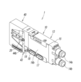
- FIG. 1 is a perspective view of a spool-type switching valve according to an embodiment of the present invention
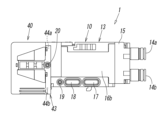
- FIG. 2 is a plan view of a spool type switching valve.
- FIG. 2 is a side view of a spool type switching valve.
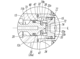
- 4 is a cross-sectional view of the spool-type switching valve taken along the line IV-IV in FIG. 2.
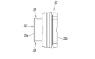
- FIG. 4 is a side view of the second piston.
- FIG. 4 is a rear view of the second piston.
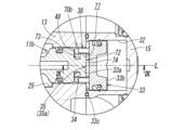
- FIG. 7 is an enlarged cross-sectional view of a portion viewed from the arrow VII in FIG. 4 .
- FIG. 11 is an enlarged cross-sectional view of the coupling diagram in a state where the second piston has moved to a forward position.
- FIG. 9 is a cross-sectional view of the connecting portion taken along line IX-IX of FIG. 8 .
- FIG. 11 is an explanatory diagram illustrating a state in which a second piston is connected to a second spool valve.
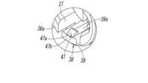
- FIG. 11 is an enlarged perspective view of a portion viewed from an arrow XI in FIG. 10 .
- FIG. 13 is an explanatory diagram illustrating a conventional method for connecting a piston to a spool valve.
- a pilot-type solenoid valve that houses two spool valves in a spool hole is described as an example of a spool-type switching valve.
- a pair of opposing side surfaces 16a, 16b, 44a, 44b of the main valve body 13 and the pilot body 43 are provided with a switching valve air supply opening 17 through which air is supplied, a switching valve exhaust opening 18 through which air is exhausted, a switching valve pilot supply opening 19 through which pilot air is supplied, and a switching valve pilot exhaust opening 20 through which pilot air is exhausted.
- the switching valve air intake openings 17, 17 are connected to each other through a switching valve air intake communication passage 21 formed in the main valve body 13.
- the switching valve exhaust openings 18, 18 are connected to each other through a switching valve exhaust communication passage 22 formed in the main valve body 13.
- the switching valve pilot supply openings 19, 19 are connected to each other through a switching valve pilot supply passage 23 formed in the main valve body 13.
- the switching valve pilot exhaust openings 20, 20 are connected to each other through a switching valve pilot exhaust passage 24 formed in the main valve body 13.
- the main valve section 10 of the spool-type switching valve 1 will be described. As shown in FIG. 4, the main valve section 10 has a piston box 60 attached to the rear end surface of the main valve body 13, and a port block 15 attached to the front end surface of the main valve body 13.
- a spool hole 25 is formed between both front and rear end faces of the main valve body 13, penetrating along the axis L.
- the spool hole 25 communicates with an air supply passage 26 located in the center in the direction of the axis L, first and second output passages 27a, 27b located on either side of the air supply passage 26, and first and second exhaust passages 28a, 28b located on either side of the first and second exhaust passages 28a, 28b.
- the first and second exhaust passages 28a, 28b communicate with each other through the switching valve exhaust communication passage 22.
- the first spool valve 11a is inserted into the rear side of the spool hole 25 so as to be freely slidable along the axis L
- the second spool valve 11b is inserted into the front side of the spool hole 25 so as to be freely slidable along the axis L. That is, the first and second spool valves 11a and 11b are housed in the spool hole 25 on the same axis L.
- the length of the spool hole 25 in the axis L direction is longer than the sum of the axial lengths of the first and second spool valves 11a and 11b.
- These spool valves 11a and 11b have a first land portion 12a located in the center in the direction of the axis L, a second land portion 12b and a third land portion 12c located on either side of the first land portion 12a, and a shaft portion 12d connecting adjacent land portions.
- the shaft portion 12d has a smaller diameter than these land portions 12a-12c.
- a first seal member 29a is attached to the outer periphery of the first land portion 12a
- a second seal member 29b is attached to the outer periphery of the second land portion 12b
- a third seal member 29c is attached to the outer periphery of the third land portion 12c.
- the third seal member 29c is a lip-type seal member that opens toward the first land portion 12a.
- the first seal member 29a opens and closes the first exhaust passage 28a connecting the first output port 14a and the switching valve exhaust opening 18 (see FIG. 3).
- the second seal member 29b opens and closes the air supply passage 26 connecting the first output port 14a and the switching valve air supply opening 17 (see FIG. 3).
- the third seal member 29c allows air to flow from the first piston chamber 61 side to the first exhaust passage 28a side, while preventing air from flowing out from the first exhaust passage 28a side to the first piston chamber 61 side.
- the first seal member 29a opens and closes the second exhaust passage 28b connecting the second output port 14b and the switching valve exhaust opening 18 (see FIG. 3).
- the second seal member 29b opens and closes the air supply passage 26 connecting the second output port 14b and the switching valve air supply opening 17 (see FIG. 3).
- the third seal member 29c allows air to flow from the second piston chamber 32 side to the second exhaust passage 28b side, while preventing air from flowing out from the second exhaust passage 28b side to the second piston chamber 32 side.
- the first spool valve 11a and the first piston 62 which are adjacent in the axial direction L, are connected by a first connecting portion 70a.
- the second spool valve 11b and the second piston 33 are connected by a second connecting portion 70b. Note that since the first and second connecting portions 70a and 70b are configured in the same way, only the second connecting portion 70b will be described, and a description of the first connecting portion 70a will be omitted.
- the second connecting portion 70b connects between the valve end surface 34 formed at the end of the second spool valve 11b facing the second piston chamber 32 in the axial direction L, and the opposing piston end surface 33a of the second piston 33.
- the second connecting portion 70b has a protrusion 72 protruding from the valve end surface 34 of the second spool valve 11b, and an insertion recess 77 provided on the piston end surface 33a of the second piston 33 into which the protrusion 72 is inserted.
- the valve end surface 34 is formed in an annular shape extending in a direction perpendicular to the axis L (hereinafter referred to as the radial direction).
- a cylindrical protrusion 72 protrudes from this valve end surface 34.
- the protrusion 72 extends coaxially with the axis L, and an engagement groove 73 is provided around the axis L on the rear side of the protrusion 72.
- the protrusion 72 has an outer shape formed in a polygonal shape around the axis L. In this embodiment, the protrusion 72 has an outer shape formed in an octagonal shape.
- the protrusion 72 has a smaller diameter than the outer diameter of the third land portion 12c of the second spool valve 11b.
- the tip of the protrusion 72 (the front end in the direction of the axis L) is provided with a flat end surface 74 extending in the radial direction. This flat end surface 74 abuts against the flat end surface 35a of the stopper portion 35 of the second piston 33, which will be described later.
- the second piston 33 is formed in a cylindrical shape.
- the second piston 33 has a front surface 33b on which pilot air acts, and a piston end surface 33a which is a back surface facing away from the front surface 33b.
- the front surface 33b and the piston end surface 33a extend in the radial direction.
- an annular wall portion 36 is erected on the piston end surface 33a.
- An insertion recess 77 is formed on the inside of this wall portion 36.
- the inner surface of the insertion recess 77 is formed in a polygonal shape around the axis L when viewed in the direction of the axis L.
- the wall portion 36 is formed in a cylindrical shape, and the insertion recess 77 is formed in an octagonal shape similar to the outer shape of the protruding portion 72 of the second spool valve 11b. Therefore, by inserting the protruding portion 72 into the insertion recess 77, the second spool valve 11b and the second piston 33 can be integrally connected around the axis L.
- the wall portion 36 includes a notched groove portion 37 cut along the axis L direction, and an engagement portion 38 provided in the notched groove portion 37 and engaged with the engagement groove portion 73.
- the engagement portion 38 has a leg portion 39 extending along the axis L direction and having a base end portion connected to the piston end surface 33a, and an engagement claw portion 47 protruding radially inwardly from the tip of the leg portion 39 centered on the axis L.
- the notched groove portions 37 are provided in the wall portion 36 at positions facing each other with the axis L at the center. That is, the notched groove portions 37 are formed in the wall portion 36 at equal angular intervals (approximately 180 degrees) around the axis L.
- the tip portion of the notched groove portion 37 opens at the tip of the wall portion 36, and the base end portion of the notched groove portion 37 communicates with a recess 33c provided in the piston end surface 33a.
- the recess 33c extends radially outward from the base end of the cutout groove 37 and opens onto the outer circumferential surface of the second piston 33.
- the legs 39 are arranged at positions with a gap from each of a pair of inner surfaces of the wall portion that separates the cutout groove portion 37.
- the legs 39 stand upright from the bottom surface of the recess 33c and extend along the axis L direction within the cutout groove portion 37.
- the legs 39 are formed in a rectangular parallelepiped shape, and a hole 39a that penetrates radially is provided in the middle of the legs 39.
- the legs 39 are elastically deformable in the radial direction.
- the engagement claw portion 47 protrudes into and engages with the engagement groove portion 73 when the protrusion 72 is inserted into the insertion recess 77.
- the engagement claw portion 47 also has an inclined surface 47a at its radially inner tip that inclines radially outward as it approaches the valve end face 34 of the second spool valve 11b. Therefore, when the tip of the protrusion 72 is pressed against the inclined surface 47a when the protrusion 72 is inserted into the insertion recess 77, the engagement claw portion 47 is easily opened radially outward as the leg portion 39 elastically deforms, thereby enabling the protrusion 72 to be smoothly inserted into the insertion recess 77.
- the tip of the engagement portion 38 and the top surface 36a facing the valve end surface 34 of the wall portion 36 are located on the same plane perpendicular to the axis L. That is, the claw end surface 47b facing the valve end surface 34 of the engagement claw portion 47 and the top surface 36a of the wall portion 36 are located on the same plane perpendicular to the axis L.
- the tip of the engagement portion 38 may protrude toward the valve end surface 34 beyond the top surface 36a of the wall portion 36.
- the contact between the protrusion 72 of the second spool valve 11b and the piston end face 33a (stopper portion 35) of the second piston 33 is by the contact between the flat end faces 74, 35a perpendicular to the axis L, as shown in Figures 6 and 9.
- a stopper portion 35 against which the tip of the protrusion 72 contacts is provided at the bottom of the insertion recess 77, and this stopper portion 35 is a flat end face 35a extending radially perpendicular to the axis L.
- the flat end surface 35a is formed on the same plane as the piston end surface 33a, and is formed in an elliptical shape when viewed in the direction of the axis L.
- the elliptical flat end surface 35a is formed symmetrically with respect to the central axis L1 that passes through the center of the bottom of the insertion recess 77 and connects the pair of legs 39.
- the shape of the flat end surface 35a is not limited to an elliptical shape, and may be a circle, a rectangle, etc.
- a groove 35b is provided in the flat end surface 35a.
- the tip of the protruding portion 72 of the second spool valve 11b is provided with a flat end surface 74 that is perpendicular to the axis L.
- this flat end surface 74 is also formed in an elliptical shape similar to the flat end surface 35a. Furthermore, when the protruding portion 72 is inserted into the insertion recess 77, the flat end surface 74 can abut against the flat end surface 35a in a tight contact state.
- FIG. 7 and 8 show a state in which the second piston 33 moves to the rear end position (retracted position) and the front end position (advanced position) of the second piston chamber 32, and the tip of the protrusion 72 abuts against the stopper portion 35.
- the second connecting portion 70b forms a gap 48 between the valve end surface 34 of the second spool valve 11b and the tip of the engaging portion 38 facing it.
- this gap 48 is formed between the valve end surface 34 of the second spool valve 11b and the claw portion end surface 47b of the engaging claw portion 47 facing it. Therefore, there is no risk of the valve end surface 34 of the second spool valve 11b abutting against the engaging claw portion 47, and damage to the engaging portion 38 can be prevented in advance.
- the pilot valve section 40 is provided with first and second pilot solenoid valves 41a and 41b that drive the first and second spool valves 11a and 11b.
- Each of the first and second pilot solenoid valves 41a and 41b has a first and second pilot inlet flow passage 79a and 79b, a first and second pilot output flow passage 80a and 80b, and a first and second pilot exhaust flow passage 81a and 81b.
- the first and second pilot solenoid valves 41a and 41b are configured to selectively connect the first and second pilot output flow passages 80a and 80b to the first and second pilot inlet flow passages 79a and 79b or the first and second pilot exhaust flow passages 81a and 81b by energizing and de-energizing the solenoids 41a1 and 41b1.
- the first and second pilot inlet passages 79a, 79b communicate with the switching valve pilot supply passage 23 through a pilot input passage 109 formed across the pilot body 43 and the main valve body 13.
- the first pilot output passage 80a also communicates with the first piston chamber 61 through a first pilot supply communication passage 104a formed across the pilot body 43 and the piston box 60.
- the second pilot output passage 80b also communicates with the second piston chamber 32 through a second pilot supply communication passage 104b formed across the pilot body 43, the piston box 60, and the main valve body 13.
- the first and second pilot exhaust passages 81a, 81b also communicate with a pilot exhaust passage 105 formed across the pilot body 43 and the piston box 60.
- the pilot exhaust passage 105 also communicates with the switching valve pilot exhaust passage 24 on its upstream side.
- the pilot exhaust passage 105 extends across the pilot body 43 and the piston box 60, and also extends to the first exhaust passage 28a through the gap formed between the third seal member 29c and the spool hole 25.
- the third seal member 29c is a lip-type seal member that opens toward the second land portion 12b side, and allows air to flow from the first piston 62 side to the first exhaust passage 28a side, while preventing air from flowing from the first exhaust passage 28a side to the first piston 62 side.
- Each of the first and second pilot solenoid valves 41a, 41b has a pilot valve body 82 on the front side.
- the pilot valve body 82 has inlet valve bodies 45a, 45b and exhaust valve bodies 46a, 46b arranged in the front-rear direction and interlocking with each other.
- the inlet valve body 45a or the inlet valve body 45b is opened to individually connect the first pilot inlet flow path 79a and the first pilot output flow path 80a, or the second pilot inlet flow path 79b and the second pilot output flow path 80b.
- the connecting operation for connecting the second spool valve 11b and the second piston 33 will be described.
- the second piston 33 is placed on the tip side of the protruding portion 72 of the second spool valve 11b with the insertion recess 77 of the second piston 33 facing the second spool valve 11b.
- at least one of the second spool valve 11b and the second piston 33 is moved in a direction approaching each other to insert the protruding portion 72 into the insertion recess 77.
- the engaging claw portion 47 of the second piston 33 and the engaging groove portion 73 of the second spool valve 11b are engaged with each other, and the second spool valve 11b and the second piston 33 are connected.
- the second spool valve 11b and the second piston 33 can be coupled to each other by linearly moving them closer to each other. This simplifies the coupling process, and the second spool valve 11b and the second piston 33 can be coupled efficiently.
Landscapes
- Engineering & Computer Science (AREA)
- General Engineering & Computer Science (AREA)
- Mechanical Engineering (AREA)
- Multiple-Way Valves (AREA)
- Fluid-Driven Valves (AREA)
- Sliding Valves (AREA)
Abstract
Description
11a 第1スプール弁(スプール弁)
11b 第2スプール弁(スプール弁)
13 主弁ボディ(ボディ)
14a 第1出力ポート(出力ポート)
14b 第2出力ポート(出力ポート)
15 ポートブロック(ボディ)
17 切換弁給気用開口(給気用のポート)
18 切換弁排気用開口(排気用のポート)
25 スプール孔
32 第2ピストン室(ピストン室)
33 第2ピストン(ピストン)
33a ピストン端面
33c 凹部
34 弁端面
35 ストッパ部
35a、74 平端面
36 壁部
36a 頂面
37 切り欠き溝部
38 係合部
39 脚部
47 係合爪部
47a 傾斜面
48 隙間
60 ピストン箱(ボディ)
61 第1ピストン室(ピストン室)
62 第1ピストン(ピストン)
70a 第1連結部(連結部)
70b 第2連結部(連結部)
72 突出部
73 係合溝部
77 挿入凹部
L 軸線(軸)
Claims (8)
- 軸方向に延びるスプール孔、及び前記スプール孔の軸方向の端部にピストン室を有するボディと、前記スプール孔に摺動自在に収容されたスプール弁と、前記ピストン室に摺動自在に収容されたピストン、とを備え、前記ボディには給気用、排気用、出力用のポートが設けられ、前記ピストン室に対するパイロットエアの給排によって前記ピストンと共に前記スプール弁を駆動させることにより、前記ポート間の連通状態を選択的に切り換え可能に構成されたスプール式切換弁であって、
前記スプール弁における前記軸方向の前記ピストン室側の端部に形成された弁端面と、これに対向する前記ピストンのピストン端面との間に、これらを連結する連結部が設けられ、
前記連結部は、前記スプール弁の前記弁端面に突設された突出部と、前記ピストンの前記ピストン端面に設けられて前記突出部が挿入された挿入凹部と、を有し、
前記突出部には、その前記軸周りに係合溝部が設けられ、
前記挿入凹部は、前記ピストン端面から立設された環状の壁部の内側に形成されており、
前記壁部は、前記軸方向に沿って切り欠かれた切り欠き溝部と、前記切り欠き溝部に設けられて前記係合溝部に係合された係合部と、を含んでおり、
前記係合部は、前記軸方向に沿って延びて基端部が前記ピストン端面に結合された脚部と、前記脚部の先端部に前記軸を中心として径方向内側へ突設された係合爪部と、を有し、
前記係合爪部は、前記突出部が前記挿入凹部に挿入された状態で前記係合溝部と係合されており、
前記脚部は、前記軸を中心として径方向外側に弾性変形可能である、
ことを特徴とするスプール式切換弁。 - 前記係合爪部は、その径方向内側の先端部に、前記スプール弁の前記弁端面側に向かうに従って径方向外側に傾く傾斜面を有している、
ことを特徴とする請求項1に記載のスプール式切換弁。 - 前記脚部が設けられた前記ピストン端面には、凹部が設けられており、
前記脚部の基端部は、前記凹部の底面から立設されている、
ことを特徴とする請求項1に記載のスプール式切換弁。 - 前記挿入凹部の底部には、前記突出部の先端部が当接するストッパ部が設けられ、
前記突出部の先端部が前記ストッパ部に当接した状態において、前記スプール弁の前記弁端面と、これに対向する前記係合部の先端との間に隙間が形成される、
ことを特徴とする請求項1に記載のスプール式切換弁。 - 前記スプール弁の前記突出部と前記ピストンの前記ストッパ部の当接は、前記軸と直交する平端面同士の当接によるものである、
ことを特徴とする請求項4に記載のスプール式切換弁。 - 前記係合部の先端と、前記壁部の前記弁端面と対向する頂面とは、前記軸方向と直交する同一平面上に位置している、
ことを特徴とする請求項4に記載のスプール式切換弁。 - 前記壁部において、前記切り欠き溝部は、前記軸周りに等角度間隔に複数形成されている、
ことを特徴とする請求項1に記載のスプール式切換弁。 - 前記スプール孔の軸方向の両端部には、前記ピストン室が設けられ、
これら前記ピストン室のそれぞれに前記ピストンが収容され、
前記スプール孔には、2つの前記スプール弁が同軸上に収容されており、
前記スプール孔の軸方向長さは、2つの前記スプール弁の軸方向長さの合計よりも長く、
前記スプール孔に収容された2つの前記スプール弁と、これら前記スプール弁のそれぞれに隣接配置された前記ピストンは、前記連結部によって連結されている、
ことを特徴とする請求項1から7のいずれか1項に記載のスプール式切換弁。
Priority Applications (3)
| Application Number | Priority Date | Filing Date | Title |
|---|---|---|---|
| KR1020257041910A KR20260027154A (ko) | 2023-06-29 | 2024-06-20 | 스풀식 스위칭 밸브 |
| EP24831810.7A EP4737773A1 (en) | 2023-06-29 | 2024-06-20 | Spool-type switching valve |
| CN202480043135.8A CN121443873A (zh) | 2023-06-29 | 2024-06-20 | 滑阀式切换阀 |
Applications Claiming Priority (2)
| Application Number | Priority Date | Filing Date | Title |
|---|---|---|---|
| JP2023107459A JP2025006576A (ja) | 2023-06-29 | 2023-06-29 | スプール式切換弁 |
| JP2023-107459 | 2023-06-29 |
Publications (1)
| Publication Number | Publication Date |
|---|---|
| WO2025004948A1 true WO2025004948A1 (ja) | 2025-01-02 |
Family
ID=93938542
Family Applications (1)
| Application Number | Title | Priority Date | Filing Date |
|---|---|---|---|
| PCT/JP2024/022325 Ceased WO2025004948A1 (ja) | 2023-06-29 | 2024-06-20 | スプール式切換弁 |
Country Status (6)
| Country | Link |
|---|---|
| EP (1) | EP4737773A1 (ja) |
| JP (1) | JP2025006576A (ja) |
| KR (1) | KR20260027154A (ja) |
| CN (1) | CN121443873A (ja) |
| TW (1) | TW202513999A (ja) |
| WO (1) | WO2025004948A1 (ja) |
Citations (3)
| Publication number | Priority date | Publication date | Assignee | Title |
|---|---|---|---|---|
| JP2008185157A (ja) * | 2007-01-30 | 2008-08-14 | Inax Corp | シリンダ式バルブにおけるパッキンの組付構造 |
| JP2011163466A (ja) * | 2010-02-10 | 2011-08-25 | Smc Corp | 減圧切換弁 |
| JP2013024345A (ja) | 2011-07-22 | 2013-02-04 | Smc Corp | 省エネバルブ |
-
2023
- 2023-06-29 JP JP2023107459A patent/JP2025006576A/ja active Pending
-
2024
- 2024-06-07 TW TW113121189A patent/TW202513999A/zh unknown
- 2024-06-20 CN CN202480043135.8A patent/CN121443873A/zh active Pending
- 2024-06-20 EP EP24831810.7A patent/EP4737773A1/en active Pending
- 2024-06-20 WO PCT/JP2024/022325 patent/WO2025004948A1/ja not_active Ceased
- 2024-06-20 KR KR1020257041910A patent/KR20260027154A/ko active Pending
Patent Citations (3)
| Publication number | Priority date | Publication date | Assignee | Title |
|---|---|---|---|---|
| JP2008185157A (ja) * | 2007-01-30 | 2008-08-14 | Inax Corp | シリンダ式バルブにおけるパッキンの組付構造 |
| JP2011163466A (ja) * | 2010-02-10 | 2011-08-25 | Smc Corp | 減圧切換弁 |
| JP2013024345A (ja) | 2011-07-22 | 2013-02-04 | Smc Corp | 省エネバルブ |
Also Published As
| Publication number | Publication date |
|---|---|
| KR20260027154A (ko) | 2026-02-27 |
| TW202513999A (zh) | 2025-04-01 |
| EP4737773A1 (en) | 2026-05-06 |
| CN121443873A (zh) | 2026-01-30 |
| JP2025006576A (ja) | 2025-01-17 |
Similar Documents
| Publication | Publication Date | Title |
|---|---|---|
| EP0500162B1 (en) | Poppet valve and valve assemblies utilizing same | |
| US6325102B1 (en) | Servo driving pilot-type solenoid valve | |
| KR0182825B1 (ko) | 절환밸브 연결체 | |
| KR100275913B1 (ko) | 파일럿식 5포트 밸브 | |
| TWI695947B (zh) | 滑軸閥 | |
| EP0898103A2 (en) | Three-port solenoid valve using valve body for five-port solenoid valve | |
| US5924439A (en) | Two-port solenoid valve using valve body for five-port solenoid valve | |
| KR101833441B1 (ko) | 스풀밸브 | |
| WO2025004948A1 (ja) | スプール式切換弁 | |
| CN202140359U (zh) | 电磁流量换向阀 | |
| CA2284480C (en) | Improved valve construction | |
| GB2154707A (en) | Inlet poppet valve | |
| JP4514324B2 (ja) | 油圧制御バルブ | |
| JP3763184B2 (ja) | 切換弁 | |
| KR20080052608A (ko) | 유압식 압력 매체를 교축하기 위한 유량 제어 밸브 | |
| JP2003120834A (ja) | スプール弁 | |
| JP4046555B2 (ja) | 三方切換弁 | |
| CN100430611C (zh) | 具有接合形壳体的阀 | |
| EP3822523A1 (en) | Spool valve | |
| JP4195838B2 (ja) | パイロット形電磁弁 | |
| JP3802984B2 (ja) | 切換弁 | |
| CN114623258B (zh) | 换向阀 | |
| TWI921541B (zh) | 真空噴射器及具備該真空噴射器的真空產生裝置 | |
| CN222558903U (zh) | 电磁换向阀和液压系统 | |
| EP0786583A2 (en) | Rotary valve and directional valve combination |
Legal Events
| Date | Code | Title | Description |
|---|---|---|---|
| 121 | Ep: the epo has been informed by wipo that ep was designated in this application |
Ref document number: 24831810 Country of ref document: EP Kind code of ref document: A1 |
|
| WWE | Wipo information: entry into national phase |
Ref document number: 2024831810 Country of ref document: EP |
|
| NENP | Non-entry into the national phase |
Ref country code: DE |
|
| ENP | Entry into the national phase |
Ref document number: 2024831810 Country of ref document: EP Effective date: 20260129 |
|
| ENP | Entry into the national phase |
Ref document number: 2024831810 Country of ref document: EP Effective date: 20260129 |