WO2025004946A1 - ポペット弁 - Google Patents
ポペット弁 Download PDFInfo
- Publication number
- WO2025004946A1 WO2025004946A1 PCT/JP2024/022322 JP2024022322W WO2025004946A1 WO 2025004946 A1 WO2025004946 A1 WO 2025004946A1 JP 2024022322 W JP2024022322 W JP 2024022322W WO 2025004946 A1 WO2025004946 A1 WO 2025004946A1
- Authority
- WO
- WIPO (PCT)
- Prior art keywords
- packing
- valve
- outer periphery
- packing mounting
- main body
- Prior art date
- Legal status (The legal status is an assumption and is not a legal conclusion. Google has not performed a legal analysis and makes no representation as to the accuracy of the status listed.)
- Ceased
Links
Images




Classifications
-
- F—MECHANICAL ENGINEERING; LIGHTING; HEATING; WEAPONS; BLASTING
- F16—ENGINEERING ELEMENTS AND UNITS; GENERAL MEASURES FOR PRODUCING AND MAINTAINING EFFECTIVE FUNCTIONING OF MACHINES OR INSTALLATIONS; THERMAL INSULATION IN GENERAL
- F16K—VALVES; TAPS; COCKS; ACTUATING-FLOATS; DEVICES FOR VENTING OR AERATING
- F16K27/00—Construction of housing; Use of materials therefor
- F16K27/02—Construction of housing; Use of materials therefor of lift valves
-
- F—MECHANICAL ENGINEERING; LIGHTING; HEATING; WEAPONS; BLASTING
- F16—ENGINEERING ELEMENTS AND UNITS; GENERAL MEASURES FOR PRODUCING AND MAINTAINING EFFECTIVE FUNCTIONING OF MACHINES OR INSTALLATIONS; THERMAL INSULATION IN GENERAL
- F16K—VALVES; TAPS; COCKS; ACTUATING-FLOATS; DEVICES FOR VENTING OR AERATING
- F16K1/00—Lift valves or globe valves, i.e. cut-off apparatus with closure members having at least a component of their opening and closing motion perpendicular to the closing faces
- F16K1/32—Details
- F16K1/34—Cutting-off parts, e.g. valve members, seats
- F16K1/36—Valve members
-
- F—MECHANICAL ENGINEERING; LIGHTING; HEATING; WEAPONS; BLASTING
- F16—ENGINEERING ELEMENTS AND UNITS; GENERAL MEASURES FOR PRODUCING AND MAINTAINING EFFECTIVE FUNCTIONING OF MACHINES OR INSTALLATIONS; THERMAL INSULATION IN GENERAL
- F16K—VALVES; TAPS; COCKS; ACTUATING-FLOATS; DEVICES FOR VENTING OR AERATING
- F16K1/00—Lift valves or globe valves, i.e. cut-off apparatus with closure members having at least a component of their opening and closing motion perpendicular to the closing faces
- F16K1/32—Details
- F16K1/34—Cutting-off parts, e.g. valve members, seats
- F16K1/42—Valve seats
-
- F—MECHANICAL ENGINEERING; LIGHTING; HEATING; WEAPONS; BLASTING
- F16—ENGINEERING ELEMENTS AND UNITS; GENERAL MEASURES FOR PRODUCING AND MAINTAINING EFFECTIVE FUNCTIONING OF MACHINES OR INSTALLATIONS; THERMAL INSULATION IN GENERAL
- F16K—VALVES; TAPS; COCKS; ACTUATING-FLOATS; DEVICES FOR VENTING OR AERATING
- F16K1/00—Lift valves or globe valves, i.e. cut-off apparatus with closure members having at least a component of their opening and closing motion perpendicular to the closing faces
- F16K1/32—Details
- F16K1/34—Cutting-off parts, e.g. valve members, seats
- F16K1/46—Attachment of sealing rings
-
- F—MECHANICAL ENGINEERING; LIGHTING; HEATING; WEAPONS; BLASTING
- F16—ENGINEERING ELEMENTS AND UNITS; GENERAL MEASURES FOR PRODUCING AND MAINTAINING EFFECTIVE FUNCTIONING OF MACHINES OR INSTALLATIONS; THERMAL INSULATION IN GENERAL
- F16K—VALVES; TAPS; COCKS; ACTUATING-FLOATS; DEVICES FOR VENTING OR AERATING
- F16K1/00—Lift valves or globe valves, i.e. cut-off apparatus with closure members having at least a component of their opening and closing motion perpendicular to the closing faces
- F16K1/32—Details
- F16K1/48—Attaching valve members to screw-spindles
-
- F—MECHANICAL ENGINEERING; LIGHTING; HEATING; WEAPONS; BLASTING
- F16—ENGINEERING ELEMENTS AND UNITS; GENERAL MEASURES FOR PRODUCING AND MAINTAINING EFFECTIVE FUNCTIONING OF MACHINES OR INSTALLATIONS; THERMAL INSULATION IN GENERAL
- F16K—VALVES; TAPS; COCKS; ACTUATING-FLOATS; DEVICES FOR VENTING OR AERATING
- F16K41/00—Spindle sealings
- F16K41/02—Spindle sealings with stuffing-box ; Sealing rings
Definitions
- the present invention relates to a poppet valve that opens and closes a flow passage by moving a seal member (packing) attached to a valve rod into and out of contact with a valve seat portion formed in a valve housing so as to surround the opening of the flow passage.
- Patent Document 1 discloses a valve stem (valve rod) seal member formed from a rubber lining (see Figure 1) and one formed from a packing (see Figure 4).
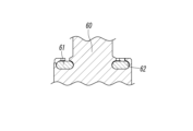
- a packing mounting groove 62 in the valve rod 60 that can accommodate both the inner and outer periphery of the packing 61, as shown in FIG. 12, for example.
- the technical objective of the present invention is to reliably attach a packing to a valve rod in a poppet valve having a sealing member made of packing so that the packing does not fall off the valve rod when the poppet valve is in operation.
- the poppet valve of the present invention has a valve housing having a flow passage therein, and a valve rod accommodated in the valve housing so as to be freely displaced.
- the poppet valve opens and closes the flow passage by moving a ring-shaped packing attached to the valve rod into and out of contact with a ring-shaped valve seat portion formed in the valve housing so as to surround the opening of the flow passage.
- the valve rod has a cylindrical packing attachment portion, and an annular packing attachment surface surrounding the central axis of the valve rod is formed on the end face of the packing attachment portion facing the valve seat portion.
- the packing has inner and outer peripheries, a first side surface that contacts and separates from the valve seat portion, and a second side surface on the opposite side.
- the inner periphery With the second side surface in contact with the packing attachment surface, the inner periphery is fitted into a packing support groove formed at the inner diameter end of the packing attachment surface, and the outer periphery is held between a packing retainer member attached to the packing attachment portion and the packing attachment surface, thereby being attached to the packing attachment surface.
- the packing retaining member has a main body portion for attachment to the packing mounting portion, and a ring-shaped locking portion bent inwardly from the cylindrical tip portion of the main body portion, the tip portion covering the outer periphery of the packing, and the locking portion abutting the first side surface of the packing at a position close to the outer periphery, whereby the outer periphery of the packing is embraced between the tip portion and locking portion and the packing mounting surface.
- the engaging portion of the packing gland member may have a plurality of notches formed in the radial direction.
- the packing support groove is formed between an annular groove forming portion formed on the valve rod and the packing mounting surface, the outer diameter of the groove forming portion is smaller than the outer diameter of the packing mounting portion, the outer peripheral end of the groove forming portion faces the inner peripheral end of the locking portion of the packing retainer member, and an annular space portion is formed between the outer peripheral end of the groove forming portion and the inner peripheral end of the locking portion, in which the valve seat portion is interposed when the packing approaches and separates from the valve seat portion.
- a recessed step for mounting the main body of the packing retainer member is formed on the outer periphery of the packing mounting portion, and by making the step of the recessed step equal to the thickness of the main body, the outer periphery of the packing mounting portion and the outer periphery of the main body of the packing retainer member can be positioned on the same cylindrical surface.
- the inner periphery of the packing is fitted into the packing support groove, and the outer periphery of the packing is held between the packing retainer member and the packing mounting surface when it is mounted on the packing mounting surface of the valve rod. This allows the packing to be firmly and securely mounted on the valve rod so that it will not fall off when the switching valve is operating.
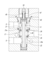
- FIG. 1 is a perspective view showing one embodiment of a poppet valve according to the present invention
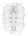
- 2 is a cross-sectional view of a main portion of the poppet valve of FIG. 1 , showing only a valve portion of the poppet valve.
- FIG. 3 is an enlarged view of a main part of FIG. 2 .
- FIG. 4 is an enlarged view of a main portion of FIG. 3 .
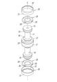
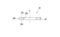
- FIG. FIG. 6 is an exploded view of FIG.
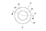
- FIG. 8 is a cross-sectional view taken along line VIII-VIII in FIG. 7.
- FIG. 2 is a cross-sectional view of a main portion showing a preferred mounting example of a poppet valve.
- FIGS 1 and 2 show an electromagnetically operated three-port valve as an example of a poppet valve 1 according to the present invention.
- This poppet valve 1 has a valve portion 2 and an electromagnetically operated portion 4 connected to the upper end of the valve portion 2 via a connecting block 3.
- the valve section 2 has a square block-shaped valve housing 5, with a first port 6 and a third port 8 opened on one side (front) of the valve housing 5, and a second port 7 opened on the other side (back) of the valve housing 5.
- the first port 6 functions as an input port by being connected to a pressure fluid source such as air
- the second port 7 functions as an output port by being connected to a fluid pressure device such as an air cylinder
- the third port 8 can function as an exhaust port by being open to the outside.
- the valve housing 5 has a valve hole 10 formed therein that extends from a first end (upper end) 5a on the electromagnetic operating unit 4 side to near a second end (lower end) 5b on the opposite side, and the first port 6, second port 7, and third port 8 communicate with the valve hole 10 through communication openings 6a, 7a, and 8a at different positions in the direction of the central axis L.
- a valve rod 11 is inserted into the valve hole 10 so that it can be displaced freely in the direction of the central axis L of the valve hole 10.
- An annular flow passage 14 that leads to the communication port 6a is formed in the sleeve 12 so as to surround the sleeve 12, and multiple connection holes 14a that connect the annular flow passage 14 and the valve hole 10 are formed in the radial direction.
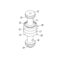
- the valve rod 11 is made of a metal such as stainless steel or iron, and as can be seen from Figures 3 to 6, has a first land 15 at one end (upper end) that seals the upper end of the valve hole 10, a second land 16 at the other end (lower end) that seals the lower end of the valve hole 10, and a central packing mounting portion 17 located within a valve chamber 18 formed in the center of the valve hole 10 in the direction of the central axis L, and a sealing O-ring 19 is attached to each of the first land 15 and second land 16.
- a metal such as stainless steel or iron
- the first port 6 and the third port 8 communicate with the valve chamber 18 at opposing positions above and below in the direction of the central axis L through the flow paths 21, 22 that are part of the valve hole 10 and their openings 21a, 22a, and the second port 7 communicates with the valve chamber 18 at the intermediate position between the upper and lower openings 21a, 22a through the communication port 7a.
- a ring-shaped first valve seat portion 24 and a second valve seat portion 25 are formed so as to surround the openings 21a, 22a at the portion where the openings 21a, 22a communicate with the valve chamber 18.
- the first valve seat portion 24 is formed in the sleeve 12 so as to surround the opening 21a of the flow path 21 leading to the first port 6
- the second valve seat portion 25 is formed in a part of the valve housing 5 so as to surround the opening 22a of the flow path 22 leading to the third port 8.
- the sleeve 12 since the sleeve 12 is attached to the valve housing 5, it can be considered to be a part of the valve housing 5, and therefore the first valve seat portion 24 formed in the sleeve 12 can be considered to be formed in a part of the valve housing 5.
- the packing mounting portion 17 of the valve rod 11 is cylindrical, and flat packing mounting surfaces 27 for mounting a ring-shaped packing 26 forming a sealing member are formed on the end face of the packing mounting portion 17 facing the first valve seat portion 24 at one end (upper end) in the direction of the central axis L, and on the end face of the packing mounting portion 17 facing the second valve seat portion 25 at the other end (lower end) in the direction of the central axis L.
- the packing 26 is mounted on each packing mounting surface 27, 27 by fitting the inner peripheral portion 26a of the packing 26 into a packing support groove 29 formed at the inner diameter end of the packing mounting surface 27, and by holding the outer peripheral portion 26b of the packing 26 in a packing retaining member 30 attached to the outer periphery of the packing mounting portion 17.
- the cylindrical shape of the packing mounting portion 17 may be a cylindrical shape with a constant diameter as a whole, or a barrel-like cylindrical shape with a slightly bulging center, as shown in Figures 3 and 4.
- the packing 26 is formed into a ring shape from an elastic material such as synthetic rubber, and as shown in Figures 7 and 8, has the inner peripheral portion 26a, the outer peripheral portion 26b, a flat first side surface 26c that contacts and separates from the valve seat portions 24 and 25, and a flat second side surface 26d that contacts closely with the packing mounting surface 27.
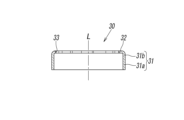
- the packing retainer member 30 is separate from the valve rod 11 and is formed, for example, by pressing a stainless steel plate. As is clear from Figs. 4, 9 and 10, it has a cylindrical main body 31 for attachment to the packing mounting portion 17 and a ring-shaped locking portion 32 that bends inward from the tip of the main body 31.
- the main body 31 has a base end 31a and a tip end 31b that is connected to the locking portion 32.
- the base end 31a is fitted and fixed to the outer periphery of the packing mounting portion 17, the tip end 31b covers the outer periphery 26b of the packing 26, and the locking portion 32 abuts against the first side surface 26c of the packing 26 at a position close to the outer periphery 26b, so that the outer periphery 26b of the packing 26 is held between the tip end 31b and locking portion 32 of the packing retainer member 30 and the packing mounting surface 27.
- the packing 26 is attached to the packing mounting surfaces 27, 27 with its inner periphery 26a fitted into the packing support groove 29 and its outer periphery 26b embraced by the packing retainer member 30, so that the packing 26 can be firmly and securely attached to the valve rod 11 so that it will not fall off the packing mounting surfaces 27, 27 when the switching valve is operating.
- a groove 28 for venting air can be formed on the outer periphery of the packing 26, and this groove 28 can prevent air from being trapped between the outer periphery 26b of the packing 26 and the packing mounting surface 27, 27 when the outer periphery 26b of the packing 26 is held between the packing retaining member 30 and the packing mounting surface 27, 27, i.e., the tip 31b and engagement portion 32 of the packing retaining member 30, the outer periphery 26b of the packing 26, and the packing mounting surface 27.
- the locking portion 32 of the packing retainer member 30 can have a plurality of notches 33 formed radially, recessed in the radial direction of the locking portion 32. These notches 33 can increase the flow path area when the packing 26 moves away from the valve seat portions 24, 25, thereby increasing the air flow rate.
- the depth of the notch 33 is a depth d that does not reach from the inner diameter end 32a to the outer diameter end 32b of the engagement portion 32.
- the depth can also be formed to a depth D that reaches from the inner diameter end 32a to the outer diameter end 32b of the engagement portion 32.
- a recessed step 35 is formed on the outer periphery of the packing mounting portion 17 at the portion where the base end 31a of the main body 31 of the packing retainer member 30 fits, and the step of this recessed step 35 is made equal to the thickness of the main body 31, so that the outer periphery of the packing mounting portion 17 and the outer periphery of the main body 31 of the packing retainer member 30 are positioned on the same cylindrical surface, preventing a step from being formed between the two outer periphery surfaces. This prevents turbulence caused by the step from occurring when air flows along the outer periphery of the packing mounting portion 17 during operation of the poppet valve 1.
- the packing retainer member 30 can be fixed to the packing mounting portion 17 by spot welding, crimping, gluing, screwing, or other methods depending on the materials of the packing retainer member 30 and the packing mounting portion 17.
- the base end portion 31a of the main body portion 31 of the packing retainer member 30 does not necessarily have to be cylindrical, and can have any shape that can be fixed to the packing mounting portion 17.
- the packing support groove 29 is formed between an annular groove forming portion 36 formed in the packing mounting portion 17 and the packing mounting surface 27.
- the outer diameter of the groove forming portion 36 is smaller than the outer diameter of the packing mounting portion 17, and the outer peripheral end of the groove forming portion 36 faces the inner peripheral end of the locking portion 32 in the packing retainer member 30, and a ring-shaped space portion 37 is formed between the outer peripheral end of the groove forming portion 36 and the inner peripheral end of the locking portion 32, in which the valve seat portions 24, 25 are interposed when the packing 26 approaches or leaves the valve seat portions 24, 25.
- a rod return spring 39 is interposed at the lower end of the valve hole 10 between a hole end wall 38 that closes the lower end and the lower end surface of the valve rod 11, and the rod return spring 39 constantly urges the valve rod 11 upward.
- the valve rod 11 has a central hole 40 penetrating the interior of the valve rod 11 in the direction of the central axis L, and a communicating hole 41 connecting the central hole 40 to the flow path 22 leading to the third port 8.
- a displacement member 42 is housed inside the sleeve 12 so as to be freely displaceable in the direction of the central axis L, and the lower surface of the displacement member 42 abuts against the upper end surface of the valve rod 11 .
- the displacement member 42 has a short cylindrical shape and has a central hole 43 that penetrates the displacement member 42 in the direction of the central axis L, and a plurality of engagement holes 44 that extend in a direction perpendicular to the central hole 43.
- the lower end of a transmission shaft 45 is inserted into the central hole 43 so that it can be displaced in the direction of the central axis L, and an engagement pin 46 attached to the transmission shaft 45 is inserted into the engagement hole 44.
- a head 45 a which also serves as a spring seat is formed at the upper end of the transmission shaft 45 , and a coil-shaped core return spring 47 is interposed between the lower surface of the head 45 a and the upper surface of the displacement member 42 .
- the electromagnetic operating unit 4 has an operating unit housing 50, and is connected to the upper end of the valve unit 2 via the connecting block 3 by screwing the lower end of a connecting shaft 51 protruding from the underside of the operating unit housing 50, which has a male thread on its outer periphery, into a connecting hole 52 of the connecting block 3, which has a female thread on its inner periphery.
- the operation unit housing 50 contains a solenoid mechanism (not shown) that converts electrical energy into mechanical energy.
- This solenoid mechanism has an electromagnetic coil and a fixed core that generate a magnetic field when current is applied, a movable core that is attracted to the fixed core and displaced downward when a magnetic field is generated, and a push rod 53 that displaces together with the movable core.
- the push rod 53 is accommodated in a rod accommodating hole 54 that extends inside the connecting shaft 51 along the central axis L so that it can be displaced freely.
- the lower end of the push rod 53 is located in the large diameter portion 54a at the lower end of the rod accommodating hole 54 and abuts against the head 45a at the upper end of the transmission shaft 45 that fits into the large diameter portion 54a.
- An electrical connection portion 55 is provided on the operation portion housing 50, and a lead wire 57 is connected to the electrical connection portion 55 by a connector 56, so that power is supplied to the electromagnetic coil through the lead wire 57.
- a known solenoid mechanism can be applied to the present invention as is, detailed illustration and description thereof will be omitted.
- Figures 2, 3 and 4 show the case when the electromagnetic operating unit 4 is off (not energized).
- the push rod 53 is not pushed down by the movable iron core, but is pushed up through the transmission shaft 45 by the biasing force of the iron core return spring 47, and occupies the elevated position shown in the figure together with the transmission shaft 45.
- the engagement pin 46 engages with the upper end wall of the engagement hole 44 of the displacement member 42, and the displacement member 42 also occupies the elevated position integrally with the transmission shaft 45.
- valve rod 11 is pushed up by the rod return spring 39 to occupy the first position shown in the figure, and the upper packing 26 in the packing mounting portion 17 abuts against the first valve seat portion 24 to close the opening 21a of the flow path 21, while the lower packing 26 moves away from the second valve seat portion 25 to open the opening 22a of the flow path 22.
- the flow path connecting the first port 6 and the second port 7 is blocked, and the flow path connecting the second port 7 and the third port 8 is connected.
- the upper packing 26 in the packing mounting portion 17 moves away from the first valve seat portion 24 to open the opening 21a of the flow path 21, and the lower packing 26 abuts against the second valve seat portion 25 to close the opening 22a of the flow path 22.
- the flow path connecting the first port 6 and the second port 7 is connected, and the flow path connecting the second port 7 and the third port 8 is blocked.
- an electromagnetically operated three-port valve is shown as the poppet valve 1, but the poppet valve 1 according to the present invention may be a valve operated by a method other than electromagnetic operation, for example, a mechanically operated, manually operated, or pilot operated valve, or may be a valve other than a three-port valve, for example, a two-port valve.
- valve housing 11 valve rod 17 packing mounting portion 21, 22 flow passage 21a, 22a opening 24, 25 valve seat portion 26 packing 26a inner peripheral portion 26b outer peripheral portion 26c first side surface 26d second side surface 27 packing mounting surface 29 packing support groove 30 packing retainer member 31 main body portion 31a base end portion 31b tip portion 32 engagement portion 33 notch 35 recessed step portion 36 groove forming portion 37 space portion
Landscapes
- Engineering & Computer Science (AREA)
- General Engineering & Computer Science (AREA)
- Mechanical Engineering (AREA)
- Lift Valve (AREA)
Abstract
Description
これに対し、シール部材をパッキンにより形成したポペット弁の場合には、弁ロッドにライニング加工やライニング加工後の仕上げ加工等を施す必要がないため、製造が容易で安価であるという利点を有する。
ところが、後者のようにシール部材をパッキンで形成した場合、特許文献1の図4に示すように、弁ロッドにパッキン装着する場合、前記弁ロッドにパッキン装着溝を形成し、このパッキン装着溝に前記リング状のパッキンの内周側だけを嵌め込んで装着しているため、ポペット弁の動作時に前記パッキンが前記パッキン装着溝から脱落するおそれがあった。
この場合、前記パッキン押え部材の前記係止部には、複数の切欠が放射方向に形成されていてもよい。
なお、図9に示すように、前記切欠33の深さは、前記係止部32の内径端32aから外径端32bまで達しない深さdであるが、図9に1つの切欠33aについて示すように、その深さを、係止部32の内径端32aから外径端32bまで達する深さDに形成することもできる。
前記弁ロッド11には、該弁ロッド11の内部を中心軸L方向に貫通する中心孔40が形成されると共に、該中心孔40と前記第3ポート8に通じる前記流路22とを結ぶ連通孔41が形成されている。
前記変位部材42は、短円柱状をしていて、該変位部材42を前記中心軸L方向に貫通する中心孔43と、該中心孔43と直交する方向に延びる複数の係合孔44とを有し、前記中心孔43の内部に、伝達軸45の下端部が前記中心軸L方向に変位可能なるように挿入されるとともに、該伝達軸45に取り付けられた係合ピン46が前記係合孔44内に挿入されている。
前記伝達軸45の上端には、ばね座を兼ねる頭部45aが形成され、該頭部45aの下面と前記変位部材42の上面との間に、コイル状の鉄心復帰ばね47が介設されている。
なお、前記ソレノイド機構については、公知のものをそのまま本発明に応用することができるため、その詳細な図示及び説明は省略されている。
5 弁ハウジング
11 弁ロッド
17 パッキン装着部
21,22 流路
21a,22a 開口部
24,25 弁シート部
26 パッキン
26a 内周部
26b 外周部
26c 第1側面
26d 第2側面
27 パッキン装着面
29 パッキン支持溝
30 パッキン押え部材
31 本体部
31a 基端部
31b 先端部
32 係止部
33 切欠
35 凹段部
36 溝形成部
37 空間部
Claims (6)
- 内部に流路を有する弁ハウジングと、該弁ハウジングの内部に変位自在に収容された弁ロッドとを有し、前記弁ロッドに取り付けたリング状のパッキンを、前記弁ハウジングに前記流路の開口部を取り囲むように形成されたリング状の弁シート部に離接させることにより、前記流路を開閉するポペット弁において、
前記弁ロッドは、円柱状をしたパッキン装着部を有し、該パッキン装着部の前記弁シート部に向き合う端面に、前記弁ロッドの中心軸を取り囲む環状のパッキン装着面が形成され、
前記パッキンは、内周部及び外周部と、前記弁シート部に接離する第1側面及び反対側の第2側面とを有し、前記第2側面を前記パッキン装着面に当接させた状態で、前記内周部を前記パッキン装着面の内径端に形成されたパッキン支持溝内に嵌合させると共に、前記外周部を、前記パッキン装着部に取り付けられたパッキン押え部材と前記パッキン装着面との間に抱持させることにより、前記パッキン装着面に装着されている、
ことを特徴とするポペット弁。 - 前記パッキン押え部材は、前記パッキン装着部に取り付けるための本体部と、該本体部の筒状をした先端部から内向きに屈曲する環状の係止部とを有し、前記先端部は前記パッキンの外周部を覆い、前記係止部は、前記パッキンの前記第1側面に前記外周部寄りの位置で当接し、それにより、前記先端部及び係止部と前記パッキン装着面との間に前記パッキンの外周部が抱持されていることを特徴とする請求項1に記載のポペット弁。
- 前記パッキン押え部材の前記係止部には、複数の切欠が放射方向に形成されていることを特徴とする請求項2に記載のポペット弁。
- 前記パッキン支持溝は、前記弁ロッドに形成された環状の溝形成部と前記パッキン装着面との間に形成され、前記溝形成部の外径は前記パッキン装着部の外径より小さく、前記溝形成部の外周端は、前記パッキン押え部材の前記係止部の内周端と対向し、前記溝形成部の外周端と前記係止部の内周端との間に、前記パッキンが前記弁シート部に接離する際に該弁シート部が介在する環状の空間部が形成されていることを特徴とする請求項2又は3に記載のポペット弁。
- 前記パッキン装着部の外周に前記パッキン押え部材の本体部を取り付けるための凹段部が形成され、該凹段部の段差を前記本体部の厚みと等しくすることにより、前記パッキン装着部の外周面と前記パッキン押え部材の本体部の外周面とを同一円柱面上に位置させたことを特徴とする請求項1から3の何れかに記載のポペット弁。
- 前記パッキン装着部の外周に前記パッキン押え部材の本体部を取り付けるための凹段部が形成され、該凹段部の段差を前記本体部の厚みと等しくすることにより、前記パッキン装着部の外周面と前記パッキン押え部材の本体部の外周面とを同一円柱面上に位置させたことを特徴とする請求項4に記載のポペット弁。
Priority Applications (3)
| Application Number | Priority Date | Filing Date | Title |
|---|---|---|---|
| EP24831808.1A EP4733638A1 (en) | 2023-06-26 | 2024-06-20 | Poppet valve |
| CN202480042325.8A CN121443872A (zh) | 2023-06-26 | 2024-06-20 | 提升阀 |
| KR1020257040368A KR20260027140A (ko) | 2023-06-26 | 2024-06-20 | 포핏 밸브 |
Applications Claiming Priority (2)
| Application Number | Priority Date | Filing Date | Title |
|---|---|---|---|
| JP2023104189A JP2025004476A (ja) | 2023-06-26 | 2023-06-26 | ポペット弁 |
| JP2023-104189 | 2023-06-26 |
Publications (1)
| Publication Number | Publication Date |
|---|---|
| WO2025004946A1 true WO2025004946A1 (ja) | 2025-01-02 |
Family
ID=93938451
Family Applications (1)
| Application Number | Title | Priority Date | Filing Date |
|---|---|---|---|
| PCT/JP2024/022322 Ceased WO2025004946A1 (ja) | 2023-06-26 | 2024-06-20 | ポペット弁 |
Country Status (6)
| Country | Link |
|---|---|
| EP (1) | EP4733638A1 (ja) |
| JP (1) | JP2025004476A (ja) |
| KR (1) | KR20260027140A (ja) |
| CN (1) | CN121443872A (ja) |
| TW (1) | TW202513997A (ja) |
| WO (1) | WO2025004946A1 (ja) |
Citations (3)
| Publication number | Priority date | Publication date | Assignee | Title |
|---|---|---|---|---|
| JP2000018400A (ja) * | 1998-07-02 | 2000-01-18 | Smc Corp | ポペット弁 |
| JP2006046414A (ja) | 2004-08-02 | 2006-02-16 | Smc Corp | 3ポート電磁弁 |
| WO2014068652A1 (ja) * | 2012-10-30 | 2014-05-08 | Smc株式会社 | 常閉型3ポート弁 |
-
2023
- 2023-06-26 JP JP2023104189A patent/JP2025004476A/ja active Pending
-
2024
- 2024-06-04 TW TW113120632A patent/TW202513997A/zh unknown
- 2024-06-20 CN CN202480042325.8A patent/CN121443872A/zh active Pending
- 2024-06-20 WO PCT/JP2024/022322 patent/WO2025004946A1/ja not_active Ceased
- 2024-06-20 EP EP24831808.1A patent/EP4733638A1/en active Pending
- 2024-06-20 KR KR1020257040368A patent/KR20260027140A/ko active Pending
Patent Citations (3)
| Publication number | Priority date | Publication date | Assignee | Title |
|---|---|---|---|---|
| JP2000018400A (ja) * | 1998-07-02 | 2000-01-18 | Smc Corp | ポペット弁 |
| JP2006046414A (ja) | 2004-08-02 | 2006-02-16 | Smc Corp | 3ポート電磁弁 |
| WO2014068652A1 (ja) * | 2012-10-30 | 2014-05-08 | Smc株式会社 | 常閉型3ポート弁 |
Also Published As
| Publication number | Publication date |
|---|---|
| EP4733638A1 (en) | 2026-04-29 |
| CN121443872A (zh) | 2026-01-30 |
| TW202513997A (zh) | 2025-04-01 |
| KR20260027140A (ko) | 2026-02-27 |
| JP2025004476A (ja) | 2025-01-15 |
Similar Documents
| Publication | Publication Date | Title |
|---|---|---|
| US7523763B2 (en) | Three-port electromagnetic valve | |
| JP4805320B2 (ja) | 電磁開閉弁 | |
| CA2459088C (en) | Leak-resistant solenoid valve | |
| JP4778204B2 (ja) | 電磁作動式の弁 | |
| US20020003221A1 (en) | Solenoid operated pilot valve | |
| US9929417B2 (en) | Valve device | |
| JP6502647B2 (ja) | ソレノイドバルブ | |
| WO2011122147A1 (ja) | バランスポペット式電磁弁 | |
| US6344783B1 (en) | Electromagnet, specially for actuating valves | |
| US6792975B2 (en) | Pulse-width modulated solenoid valve including axial stop spool valve | |
| US8944405B2 (en) | Solenoid valve plate | |
| US20190195383A1 (en) | Control valve assembly | |
| US3016065A (en) | Servo-valves | |
| WO2025004946A1 (ja) | ポペット弁 | |
| US20030030020A1 (en) | Solenoid-operated valve | |
| CN107497167B (zh) | 用于液压阀的夹式过滤器和具有这样的夹式过滤器的液压阀 | |
| RU2710836C9 (ru) | Гидро(пневмо)устройство и способ его изготовления | |
| JP3863763B2 (ja) | 液圧制御装置 | |
| KR0134618B1 (ko) | 솔레노이드 밸브 | |
| CN102686460A (zh) | 电磁阀以及具有这种电磁阀的驾驶员辅助装置 | |
| JP2007524050A (ja) | 漏れ抵抗性電磁弁 | |
| JP6645862B2 (ja) | 電磁弁 | |
| JP2001330167A (ja) | 弁装置 | |
| CN221569600U (zh) | 先导式电磁阀 | |
| JP7130601B2 (ja) | 電磁コイル及び弁装置 |
Legal Events
| Date | Code | Title | Description |
|---|---|---|---|
| 121 | Ep: the epo has been informed by wipo that ep was designated in this application |
Ref document number: 24831808 Country of ref document: EP Kind code of ref document: A1 |
|
| ENP | Entry into the national phase |
Ref document number: 2024831808 Country of ref document: EP Effective date: 20260126 |
|
| WWE | Wipo information: entry into national phase |
Ref document number: 2024831808 Country of ref document: EP |
|
| NENP | Non-entry into the national phase |
Ref country code: DE |
|
| ENP | Entry into the national phase |
Ref document number: 2024831808 Country of ref document: EP Effective date: 20260126 |
|
| ENP | Entry into the national phase |
Ref document number: 2024831808 Country of ref document: EP Effective date: 20260126 |