WO2025004932A1 - 脳波測定装置 - Google Patents
脳波測定装置 Download PDFInfo
- Publication number
- WO2025004932A1 WO2025004932A1 PCT/JP2024/022235 JP2024022235W WO2025004932A1 WO 2025004932 A1 WO2025004932 A1 WO 2025004932A1 JP 2024022235 W JP2024022235 W JP 2024022235W WO 2025004932 A1 WO2025004932 A1 WO 2025004932A1
- Authority
- WO
- WIPO (PCT)
- Prior art keywords
- support
- measuring device
- eeg
- head
- hole
- Prior art date
- Legal status (The legal status is an assumption and is not a legal conclusion. Google has not performed a legal analysis and makes no representation as to the accuracy of the status listed.)
- Ceased
Links
Images




Classifications
-
- A—HUMAN NECESSITIES
- A61—MEDICAL OR VETERINARY SCIENCE; HYGIENE
- A61B—DIAGNOSIS; SURGERY; IDENTIFICATION
- A61B5/00—Measuring for diagnostic purposes; Identification of persons
- A61B5/24—Detecting, measuring or recording bioelectric or biomagnetic signals of the body or parts thereof
- A61B5/25—Bioelectric electrodes therefor
- A61B5/251—Means for maintaining electrode contact with the body
- A61B5/256—Wearable electrodes, e.g. having straps or bands
-
- A—HUMAN NECESSITIES
- A61—MEDICAL OR VETERINARY SCIENCE; HYGIENE
- A61B—DIAGNOSIS; SURGERY; IDENTIFICATION
- A61B5/00—Measuring for diagnostic purposes; Identification of persons
- A61B5/24—Detecting, measuring or recording bioelectric or biomagnetic signals of the body or parts thereof
- A61B5/25—Bioelectric electrodes therefor
- A61B5/279—Bioelectric electrodes therefor specially adapted for particular uses
- A61B5/291—Bioelectric electrodes therefor specially adapted for particular uses for electroencephalography [EEG]
Definitions
- the present invention relates to an electroencephalogram measuring device.
- Electrodes are placed on the head to perform electrical measurements.
- Patent Document 1 describes how brain waves are measured by contacting the tips of electrode pins supported by an elastic member with the scalp.
- the present invention provides an EEG measuring device that allows the EEG electrodes to be in stable contact with the scalp.
- the following electroencephalogram measuring device is provided.
- a support that can be attached to the head; an elastic member that is elastically deformable and has a first through hole; an electroencephalogram electrode member held on the support via the elastic member; An electroencephalogram measuring device comprising: a holding member that passes through the first through hole, one end of which holds the electroencephalogram electrode member, and the other end of which is exposed to the outside of the support body. 2. In the electroencephalogram measuring device according to 1., An electroencephalogram measuring device, wherein the holding member is detachable from the electroencephalogram electrode member. 3. In the electroencephalogram measuring device according to 1 or 2, An electroencephalogram measuring device in which the angle of the holding member relative to the support body is variable while the holding member holds the EEG electrode member. 4.
- the elastic member of the electroencephalogram measuring device is made of an elastic material. 5.
- the electroencephalogram measuring device, wherein the elastic member is made of one or more selected from the group consisting of urethane sponge, polyethylene sponge, polypropylene sponge, and silicone rubber sponge. 6.
- the elastic material has a hardness of 30N or more and 200N or less as measured by JIS K 6400-2 ⁇ A method. 7.
- An electroencephalogram measuring device, wherein the area of the surface of the elastic member facing the head is 3 cm2 or more and 25 cm2 or less. 8.
- the support includes a base body located on the head side when the support is attached to the head, and a covering member located on the opposite side to the head side, The holding member holds the EEG electrode member in a state where the EEG electrode member passes through a second through hole and the first through hole provided in the covering member, An electroencephalogram measuring device in which the hole diameter of the second through hole is larger than the hole diameter of the first through hole.
- the present invention provides an EEG measuring device that can stably contact the EEG electrodes with the scalp.
- FIG. 1 is a diagram illustrating a partial cross section of an electroencephalogram measuring device according to an embodiment.
- 1 is a perspective view illustrating an electroencephalogram measuring device according to an embodiment.
- 1 is a perspective view illustrating an electroencephalogram measuring device according to an embodiment.
- 1 is a diagram illustrating a state in which the support is attached to a person's head.
- FIG. FIG. 13 is a diagram illustrating an example of the state of the inside of the support body.
- FIG. 13 is a diagram illustrating a state in which the support is pressed against the scalp of the head.
- 11A to 11C are diagrams illustrating an example of how to move the holding member.
- FIG. 13 is a diagram illustrating a state in which a tube is attached to a support.
- FIG. 13 is a diagram illustrating a partial cross section of an electroencephalogram measuring device with the holding member and the electroencephalogram electrode member removed from the support body.
- FIG. 13 is a diagram illustrating the structure of the side of the EEG electrode member that faces the head.
- FIG. 2 is a side view of the EEG electrode member. This is a cross-sectional view taken along line AA in FIG. 11A and 11B are diagrams illustrating examples of the relationship between a protrusion and a tube.
- FIG. 1 is a diagram illustrating a partial cross section of an EEG measuring device 10 according to an embodiment.
- the EEG measuring device 10 comprises a support 110 and an EEG electrode member 120.
- the support 110 can be worn on the head.
- the EEG electrode member 120 is held by the support 110.
- EEG can be measured by contacting the EEG electrode member 120 of the EEG measuring device 10 with the head.
- FIGS. 2 and 3 are perspective views illustrating the EEG measuring device 10 according to this embodiment.
- FIG. 4 is a diagram illustrating the state in which the support 110 is attached to a person's head 20.
- FIG. 5 is a diagram illustrating the state of the inside of the support 110 (the side into which the head 20 is inserted).
- the support 110 is helmet-shaped.
- the support 110 has a recess into which the head 20 is inserted.
- the support 110 is helmet-shaped.
- the EEG measuring device 10 is configured so that one or more EEG electrode members 120 come into contact with the head 20 when the helmet-shaped support 110 is attached to the head 20.
- the EEG measuring device 10 may include a belt 170 for fixing the support 110 to the head 20, as shown in FIG. 5.
- the side of the support 110 facing the head 20 will be referred to as the inside of the support 110, and the side opposite the inside will be referred to as the outside of the support 110.
- the direction from the inside to the outside of the support 110 is referred to as the z direction.
- the x direction, y direction, and z direction are mutually perpendicular.
- the z direction is generally the normal direction of the scalp 22. Note that the x direction, y direction, and z direction can be defined as different directions for each EEG electrode member 120 in the EEG measurement device 10.
- the holding member 140 which will be described in detail later, may be detachable from the support 110.
- Figure 2 shows the holding member 140 attached to the support 110
- Figures 3 and 4 show the holding member 140 removed from the support 110.
- the support 110 holds multiple EEG electrode members 120. With the support 110 attached to the head 20, each EEG electrode member 120 can be brought into contact with a predetermined position on the head 20. Then, EEG signals are measured using the multiple EEG electrode members 120.
- the support 110 can hold seven EEG electrode members 120.
- the positions of the seven EEG electrode members 120 can correspond to positions F3, F4, C3, C4, P3, Pz, and P4 in the International 10-20 electrode placement method.
- the number and positions of the EEG electrode members 120 provided on the support 110 are not particularly limited and can be set according to the application, etc.
- the EEG electrode member 120 is provided with a third through hole 121.
- the third through hole 121 is a hole for supplying liquid to the head 20. Providing the third through hole 121 in the EEG electrode member 120 makes it easy to inject liquid into the scalp. For example, if an auxiliary liquid containing an electrolyte is supplied to the head 20 prior to measuring EEG, the electrical contact between the scalp and the EEG electrode member 120 can be improved.
- the EEG electrode member 120 and the method of measuring EEG will be described in detail later.
- the EEG measuring device 10 further includes an elastic member 130 and a holding member 140.
- the elastic member 130 is elastically deformable.
- a first through hole 131 is provided in the elastic member 130.
- the holding member 140 passes through the first through hole 131, with one end 141 holding the EEG electrode member 120 and the other end 142 exposed to the outside of the support 110.
- the EEG electrode member 120 is held by the support 110 via the elastic member 130.
- the shape of the support 110 is determined, for example, based on the average head shape.
- head shapes vary greatly from person to person, and an element is needed to absorb these differences.
- the elastic member 130 elastically deforms when the support 110 is attached to the head 20. This allows the EEG electrode member 120 to be in stable contact with the scalp and EEG measurements to be made, even if there are individual differences in head shape (irregularities and surface angles).
- the holding member 140 can be used to move the EEG electrode member 120.
- the EEG electrode member 120 can be used to push aside the hair, allowing the EEG electrode to stably contact the scalp.
- the holding member 140 is detachable from the EEG electrode member 120. This eliminates any protrusions from the support 110 during measurement, and stabilizes the center of gravity when attached to the head 20.
- the subject can lie down while wearing the support 110, reducing noise caused by body movement, etc. EEG measurement may also be performed while the subject is moving around.
- the EEG electrode member 120 is detachable from the support 110. This allows the EEG electrode member 120 to be replaced as needed, or different types of EEG electrode member 120 to be used for different measurements.
- the support 110 with the EEG electrode member 120 and the holding member 140 attached is attached to the head 20.
- the holding member 140 may be attached to the EEG electrode member 120 after the support 110 is attached to the head 20.
- FIG. 6 is a diagram illustrating the state in which the support 110 is pressed against the scalp 22 of the head 20.
- FIG. 6 is a partial cross-sectional view of the EEG measuring device 10. The cross-section shown in FIG. 6 corresponds to the cross-section shown in FIG. 1.
- the elastic member 130 is shrunk compared to before pressing.
- the support 110 is attached to the head 20, the EEG electrode member 120 comes into contact with the scalp 22.
- the elastic member 130 deforms according to the position and angle of the scalp 22 relative to the support 110.
- the EEG electrode member 120 is pressed against the scalp 22 with a force according to the elasticity of the elastic member 130.
- the position and angle of the tip of the EEG electrode member 120 based on the support 110 can be changed to match the shape of the head 20.
- FIG. 7 is a diagram illustrating an example of how to move the holding member 140.
- FIG. 7 is a partial cross-sectional view of the EEG measurement device 10. The cross-section shown in FIG. 7 corresponds to the cross-section shown in FIG. 1.
- the angle of the holding member 140 with respect to the support 110 is variable.
- the length of the portion of the holding member 140 that is exposed to the outside from the support 110 is variable depending on the degree of contraction of the elastic member 130.
- an operator of the EEG measurement device 10 moves the holding member 140 using the support 110 as a reference.
- the operator can move the holding member 140 so as to change the angle of the holding member 140 relative to the support 110, i.e., the angle relative to the head 20. It is particularly effective to move the holding member 140 so as to rotate the other end 142 of the holding member 140 around the EEG electrode member 120 as a fulcrum.
- the operator can also push and pull the holding member 140 relative to the support 110, i.e., relative to the head 20. These movements of the holding member 140 can push aside the hair on the scalp 22, improving the contact between the EEG electrode member 120 and the scalp 22.
- the EEG measurement device 10 further includes a tube that passes through a third through-hole 121 provided in the EEG electrode member 120.
- the tube can be inserted into and removed from the third through-hole 121 of the EEG electrode member 120.
- FIG. 8 is a diagram illustrating a state in which tube 151 is attached to support 110.
- FIG. 8 is a partial cross-sectional view of EEG measurement device 10. The cross-section shown in FIG. 8 corresponds to the cross-section shown in FIG. 1. Also, FIG. 6 can be said to show support 110 in a state in which tube 151 has been removed.
- EEG measurement device 10 further includes an injection member 152 for injecting liquid 30 into tube 151.
- EEG measurement device 10 further includes a connection member 153.
- Connection member 153 is a connection member for connecting tube 151 to injection member 152.
- the auxiliary liquid is injected into the tube 151 to supply the auxiliary liquid to the scalp 22, wetting the scalp 22 as illustrated in FIG. 8.
- the auxiliary liquid is an example of the liquid 30.
- the auxiliary liquid is not particularly limited as long as it can reduce the electrical resistance between the EEG electrode member 120 and the scalp 22, but includes, for example, an electrolyte. However, it is also possible to perform EEG measurement using the EEG measurement device 10 without supplying auxiliary liquid.
- the operator removes the holding member 140 from the support 110 and begins EEG measurement.
- the EEG measuring device 10 is equipped with an EEG electrode member 120 having a third through-hole 121, and a tube 151 passing through the third through-hole 121. Therefore, auxiliary liquid can be efficiently supplied to the area where the EEG electrode member 120 and the scalp 22 are in contact.
- the auxiliary liquid can be supplied immediately before the measurement. Therefore, it is possible to use a liquid with low viscosity as the auxiliary. For example, if the auxiliary is applied before the EEG electrode member is placed on the head, there is a concern that the auxiliary will run off or evaporate before the measurement begins, and it is necessary to use a paste or gel-like auxiliary. When using a paste-like auxiliary, the auxiliary has a very high viscosity, so it is necessary to manually brush the hair aside to apply it, which is time-consuming.
- the holding member 140 can be operated in advance to brush the hair aside, and a small amount of auxiliary liquid can be injected very close to the scalp.
- an auxiliary liquid with a low viscosity equivalent to that of water it is even less affected by the hair, and the contact resistance can be significantly reduced with a small amount of liquid.
- FIG. 9 is a cross-sectional view illustrating the state of the EEG electrode member 120 and its surroundings during measurement.
- the cross-section shown in FIG. 9 corresponds to the cross-section shown in FIG. 1.
- EEG measurement can be performed with the tube 151 and holding member 140 removed from the support 110.
- the support 110 has a shape that allows it to cover at least a portion of the head 20.
- the support 110 comprises a base 111 and a covering member 112.
- the base 111 is located on the head 20 side when the support 110 is attached to the head 20.
- the covering member 112 is located on the opposite side to the head 20 side when the support 110 is attached to the head 20.
- the base 111 is made of, for example, polystyrene foam.
- the covering member 112 is made of, for example, resin.
- the covering member 112 is harder than the base 111 and can protect the head 20.
- the support body 110 does not necessarily have to include the covering member 112.
- the support 110 only needs to be able to be attached to the head 20, and may be made of, for example, cloth or rubber.
- the support 110 may be, for example, helmet-shaped, hat-shaped, or band-shaped.
- FIG. 10 is a diagram illustrating a partial cross section of the EEG measuring device 10 in a state in which the holding member 140 and the EEG electrode member 120 have been removed from the support 110.
- the cross section shown in FIG. 10 corresponds to the cross section shown in FIG. 1.
- Wiring 163, circuit 162, and wiring 165, which will be described later, are not depicted in FIG. 10.
- the elastic member 130 is housed in a hole provided in the support 110.
- the outer shape and size of the elastic member 130 are approximately the same as the inner shape and size of the hole provided in the support 110, and the elastic member 130 is fitted into the hole of the support 110.
- the elastic member 130 may fill the entire part of the hole provided in the support 110 except for the first through hole 131.
- a part of the elastic member 130 may protrude from the hole of the support 110.
- the covering member 112 is provided with a second through hole 114.
- the first through hole 131 provided in the elastic member 130 and the second through hole 114 provided in the covering member 112 are connected to each other.
- the holding member 140 holds the EEG electrode member 120 while passing through the first through hole 131 and the second through hole 114.
- the hole diameter d2 of the second through hole 114 is larger than the hole diameter d1 of the first through hole 131.
- the elastic member 130 is made of an elastic material.
- the elastic material is, for example, one or more selected from urethane sponge, polyethylene sponge, polypropylene sponge, and silicone rubber sponge.
- the elastic material may be a foam, and examples of the foam include low-resilience sponge and low-resilience elastic foam.
- the elastic member 130 may be configured not to include a spring.
- a spring When a spring is used, the repulsive force of the spring increases in proportion to the deformation of the spring. Therefore, when the deformation is large, excessive repulsive force is generated, and the subject is likely to feel pain.
- a foam elastic material when used, there is a range of displacement where the repulsive force does not increase much (is not proportional) with an increase in deformation. By configuring the elastic member 130 so that it can be used within such a range of displacement, an appropriate repulsive force can be obtained even if the deformation varies depending on the position of the EEG electrode member 120.
- the hardness H of the elastic material is, for example, 30N or more and 200N or less. From the viewpoint of further reducing the burden on the person being measured, it is preferable that the hardness H is 100N or less. Also, from the viewpoint of more stably pressing the EEG electrode member 120 against the scalp 22, it is preferable that the hardness H is 50N or more.
- the thickness t of the elastic member 130 is, for example, 10 mm or more and 100 mm or less when the support 110 is not attached to the head 20.
- the thickness t is the thickness in a direction perpendicular to the surface 132 of the elastic member 130 that faces the head 20.
- the elastic member 130 is fixed to the support 110 at one end, and the thickness t of the elastic member 130 is variable depending on the force it receives in the thickness direction.
- the elastic member 130 is fixed to the support 110 at a surface 133 opposite to the surface 132.
- the thickness t of the elastic member 130 is preferably 20 mm or more and 60 mm or less when the support 110 is not attached to the head 20.
- the area of the surface 132 of the elastic member 130 facing the head is, for example, 3 cm2 or more and 25 cm2 or less.
- a conductive part 164 is fixed inside the first through hole 131 of the elastic member 130.
- the conductive part 164 is, for example, a metal.
- a through hole is provided in the conductive part 164, and a screw groove is provided on the inside of the through hole for fixing the EEG electrode member 120.
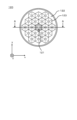
- FIG 11 is a diagram (bottom view) illustrating the structure of the side of the EEG electrode member 120 that faces the head 20.
- Figure 12 is a side view of the EEG electrode member 120.
- Figure 13 is a cross-sectional view taken along line A-A in Figure 11.
- the EEG electrode member 120 comprises a base 122 and one or more protrusions 123 provided on the base 122.
- the third through hole 121 is provided in the base 122.
- the EEG electrode member 120 further comprises a conductive member 124, wiring 127, and a cover 129.
- the conductive member 124 is, for example, a metal, and has a first portion 124a and a second portion 124b.
- the first portion 124a and the second portion 124b are integrally formed.
- the first portion 124a is tubular.
- the through hole provided in the conductive member 124 and the through hole provided in the base 122 are connected to each other, and these through holes form the third through hole 121.
- a screw groove is provided on the outside of the first portion 124a.
- the second portion 124b is plate-shaped.
- the cover 129 covers a part of the conductive member 124 and a part of the base 122.
- the cover 129 is formed, for example, using a resin and is insulating.
- the base 122 is fixed to the main surface of the second portion 124b.
- the protruding portion 123 has a first portion 123a, a conductive portion 123b, and a second portion 123c.
- a plurality of protruding portions 123 are provided on the surface of the base 122 opposite the conductive member 124 side.
- the base 122 and the first portion 123a are integrally provided by a rubber-like elastic body. There may be ten or more protruding portions 123.
- the shape of the first portion 123a is, for example, a cone or a pyramid such as a polygonal pyramid.
- the conductive portion 123b is provided so as to cover the first portion 123a.
- the tip of the first portion 123a is covered with the second portion 123c.
- the second portion 123c is a spherical member made of a gel-like material (also called hydrogel) containing water inside, and is attached so as to pierce the tip portion of the first portion 123a.
- the second portion 123c comes into contact with the head 20.
- electrolytic substances generally salt
- the scalp 22 are taken up into the second portion 123c.
- the shape of the second portion 123c is not limited to a sphere.
- the gel material constituting the second portion 123c is not particularly limited as long as it is capable of sufficient water absorption and has sufficient strength and flexibility when pressed against the head 20, but for example, an acrylic hydrogel or a silicone hydrogel can be used.
- the materials of the base 122 and the first portion 123a will be described.
- the base 122 and the first portion 123a are made of a rubber-like elastic body.
- the rubber-like elastic body is specifically rubber or a thermoplastic elastomer (also simply called “elastomer (TPE)").
- An example of rubber is silicone rubber.
- thermoplastic elastomers include styrene-based TPE (TPS), olefin-based TPE (TPO), polyvinyl chloride-based TPE (TPVC), urethane-based TPE (TPU), ester-based TPE (TPEE), and amide-based TPE (TPAE).
- the conductive portion 123b is formed, for example, using a paste containing a highly conductive metal.
- the conductive portion 123b contains, for example, one or more selected from the group consisting of copper, silver, gold, nickel, tin, lead, zinc, bismuth, antimony, or alloys thereof.
- a wiring 127 connected to the conductive portion 123b is provided inside the first portion 123a.
- the wiring 127 electrically connects the conductive portion 123b and the conductive member 124.
- the wiring 127 may be composed of, for example, conductive fibers.
- the conductive fibers may be one or more types selected from the group consisting of metal fibers, metal-coated fibers, carbon fibers, conductive polymer fibers, conductive polymer-coated fibers, and conductive paste-coated fibers. These may be used alone or in combination of two or more types.
- the outer shape of the holding member 140 is generally rod-shaped.
- a through hole is provided on the inside of the holding member 140. The through hole of the holding member 140 connects the inside and outside of the support 110 when the holding member 140 is attached to the support 110.
- the EEG electrode member 120 is attached to the conductive portion 164 (i.e., attached to the elastic member 130) by screwing the first portion 124a of the conductive member 124 into the conductive portion 164. With the EEG electrode member 120 attached to the conductive portion 164, the first portion 124a penetrates the conductive portion 164, and the tip of the first portion 124a protrudes outside the conductive portion 164.
- a screw groove is provided on the inside of one end 141 of the holding member 140.
- the holding member 140 can hold the EEG electrode member 120 by screwing the screw groove of one end 141 of the holding member 140 and the portion of the first portion 124a protruding from the conductive portion 164.
- the operator can attach and detach the holding member 140 to and from the EEG electrode member 120 by holding the other end 142 of the holding member 140 and rotating the holding member 140 around the z-direction as an axis.
- the other end 142 of the holding member 140 is provided with a connection portion for attaching the injection member 152.
- the connection portion is a part of the through hole of the holding member 140, and is configured so that the connection member 153 can be fitted into it.
- the injection member 152 is, for example, a syringe, and has a liquid storage portion.
- the tube 151 is, for example, made of metal. With the connection member 153 and the tube 151 attached to the injection member 152, the tube 151 is inserted into the third through hole 121, and the connection member 153 is fitted into the connection portion of the holding member 140. In this way, with the tube 151 inserted into the through hole of the holding member 140 and the third through hole 121 of the EEG electrode member 120, the injection member 152 and the tube 151 are fixed to the holding member 140 via the connection member 153.
- the tube 151 When the tube 151 is inserted into the third through-hole 121 of the EEG electrode member 120, the tube 151 penetrates the base 122. The liquid pushed out from the injection member 152 is supplied to the scalp 22 through the tube 151.
- FIG. 14 is a diagram illustrating the relationship between the convex portion 123 and the tube 151.
- the electrical connections in the EEG measuring device 10 are described below with reference to Figures 3, 5, 9, and 13.
- the EEG measuring device 10 further includes wiring 163, circuit 162, wiring 165, signal processing unit 160, and reference potential measurement wiring 161.
- conductive portion 164, wiring 163, circuit 162, and wiring 165 are provided for each EEG electrode member 120.
- Wiring 163 and circuit 162 are fixed to the elastic member 130 together with conductive portion 164.
- the electrical signal from the scalp 22 is transmitted to the conductive member 124 via the second portion 123c, the conductive portion 123b, and the wiring 127.
- the electrical signal thus obtained at each EEG electrode member 120 is sent from the conductive member 124 of the EEG electrode member 120 to the signal processing unit 160 via the conductive portion 164, the wiring 163, the circuit 162, and the wiring 165.
- the circuit 162 includes, for example, a preamplifier that amplifies the electrical signal from the EEG electrode member 120.
- the signal processing unit 160 acquires electrical signals from the multiple EEG electrode members 120 (from the circuit 162).
- the signal processing unit 160 performs processes such as amplification of the EEG electrical signal, analog-to-digital conversion, and frequency filtering.
- the signal processing unit 160 can also record the EEG signal data obtained by performing these processes in a recording unit provided within the signal processing unit 160.
- the signal processing unit 160 can also transmit the electroencephalogram signal data to an external device by wired or wireless communication.
- the signal processing unit 160 is realized, for example, by using an integrated circuit. It is preferable that the signal processing unit 160 has a built-in battery. This eliminates the need to connect a power line to the signal processing unit 160 to supply power. Ultimately, the subject can move or be active to a certain degree during the measurement. It is also possible to prevent noise that depends on the frequency of the power supply.
- the reference potential measurement wiring 161 connects the signal processing unit 160 and a reference electrode (not shown) to each other.
- the reference electrode is an electrode for acquiring a reference potential that serves as a reference in measuring the electroencephalogram signal.
- the reference electrode is attached to the earlobe or the upper part of the outer ear with a clip, or attached to the bone on the back side of the outer ear to acquire the reference potential.
- the EEG measuring device 10 includes a support 110, an elastic member 130, an EEG electrode member 120, and a holding member 140.
- the support 110 can be attached to the head 20.
- the elastic member 130 is elastically deformable, and is provided with a first through hole 131.
- the EEG electrode member 120 is held by the support 110 via the elastic member 130.
- the holding member 140 passes through the first through hole 131, with one end 141 holding the EEG electrode member 120 and the other end 142 exposed to the outside of the support 110. Therefore, hair can be pushed aside and the EEG electrode can be stably brought into contact with the scalp.
- EEG measuring device 20 Head 22 Scalp 110 Support 111 Base 112 Covering member 114 Second through-hole 120 EEG electrode member 121 Third through-hole 122 Base 123 Convex portion 124 Conductive member 127 Wiring 129 Cover 130 Elastic member 131 First through-hole 140 Holding member 151 Tube 152 Injection member 153 Connection member 160 Signal processing unit 161 Reference potential measurement wiring 162 Circuits 163, 165 Wiring 164 Conductive portion 170 Belt
Landscapes
- Life Sciences & Earth Sciences (AREA)
- Health & Medical Sciences (AREA)
- Medical Informatics (AREA)
- Biophysics (AREA)
- Pathology (AREA)
- Engineering & Computer Science (AREA)
- Biomedical Technology (AREA)
- Heart & Thoracic Surgery (AREA)
- Physics & Mathematics (AREA)
- Molecular Biology (AREA)
- Surgery (AREA)
- Animal Behavior & Ethology (AREA)
- General Health & Medical Sciences (AREA)
- Public Health (AREA)
- Veterinary Medicine (AREA)
- Measurement And Recording Of Electrical Phenomena And Electrical Characteristics Of The Living Body (AREA)
Priority Applications (2)
| Application Number | Priority Date | Filing Date | Title |
|---|---|---|---|
| EP24831794.3A EP4736766A1 (en) | 2023-06-27 | 2024-06-19 | Electroencephalogram measurement device |
| JP2025529684A JPWO2025004932A1 (https=) | 2023-06-27 | 2024-06-19 |
Applications Claiming Priority (2)
| Application Number | Priority Date | Filing Date | Title |
|---|---|---|---|
| JP2023104863 | 2023-06-27 | ||
| JP2023-104863 | 2023-06-27 |
Publications (1)
| Publication Number | Publication Date |
|---|---|
| WO2025004932A1 true WO2025004932A1 (ja) | 2025-01-02 |
Family
ID=93938366
Family Applications (1)
| Application Number | Title | Priority Date | Filing Date |
|---|---|---|---|
| PCT/JP2024/022235 Ceased WO2025004932A1 (ja) | 2023-06-27 | 2024-06-19 | 脳波測定装置 |
Country Status (3)
| Country | Link |
|---|---|
| EP (1) | EP4736766A1 (https=) |
| JP (1) | JPWO2025004932A1 (https=) |
| WO (1) | WO2025004932A1 (https=) |
Citations (7)
| Publication number | Priority date | Publication date | Assignee | Title |
|---|---|---|---|---|
| US6161030A (en) * | 1999-02-05 | 2000-12-12 | Advanced Brain Monitoring, Inc. | Portable EEG electrode locator headgear |
| JP2006006667A (ja) * | 2004-06-25 | 2006-01-12 | Olympus Corp | 脳機能検出装置 |
| JP2011120866A (ja) * | 2009-11-10 | 2011-06-23 | Japan Health Science Foundation | 脳波測定用電極、脳波測定用電極付きキャップ及び脳波測定装置 |
| JP2020000268A (ja) | 2018-06-25 | 2020-01-09 | 凸版印刷株式会社 | 脳波電極および脳波電極保持具 |
| JP2021094157A (ja) * | 2019-12-16 | 2021-06-24 | アルプスアルパイン株式会社 | 生体情報測定用電極 |
| CN114886428A (zh) * | 2022-06-16 | 2022-08-12 | 河南科技大学第一附属医院 | 一种脑电图电极固定帽 |
| JP2023104863A (ja) | 2022-01-17 | 2023-07-28 | ネイバー コーポレーション | ディープラーニングモデルのチューニング方法およびシステム |
-
2024
- 2024-06-19 JP JP2025529684A patent/JPWO2025004932A1/ja active Pending
- 2024-06-19 EP EP24831794.3A patent/EP4736766A1/en active Pending
- 2024-06-19 WO PCT/JP2024/022235 patent/WO2025004932A1/ja not_active Ceased
Patent Citations (7)
| Publication number | Priority date | Publication date | Assignee | Title |
|---|---|---|---|---|
| US6161030A (en) * | 1999-02-05 | 2000-12-12 | Advanced Brain Monitoring, Inc. | Portable EEG electrode locator headgear |
| JP2006006667A (ja) * | 2004-06-25 | 2006-01-12 | Olympus Corp | 脳機能検出装置 |
| JP2011120866A (ja) * | 2009-11-10 | 2011-06-23 | Japan Health Science Foundation | 脳波測定用電極、脳波測定用電極付きキャップ及び脳波測定装置 |
| JP2020000268A (ja) | 2018-06-25 | 2020-01-09 | 凸版印刷株式会社 | 脳波電極および脳波電極保持具 |
| JP2021094157A (ja) * | 2019-12-16 | 2021-06-24 | アルプスアルパイン株式会社 | 生体情報測定用電極 |
| JP2023104863A (ja) | 2022-01-17 | 2023-07-28 | ネイバー コーポレーション | ディープラーニングモデルのチューニング方法およびシステム |
| CN114886428A (zh) * | 2022-06-16 | 2022-08-12 | 河南科技大学第一附属医院 | 一种脑电图电极固定帽 |
Also Published As
| Publication number | Publication date |
|---|---|
| JPWO2025004932A1 (https=) | 2025-01-02 |
| EP4736766A1 (en) | 2026-05-06 |
Similar Documents
| Publication | Publication Date | Title |
|---|---|---|
| CN102596021B (zh) | 用于在用户的头皮上放置电极的装置 | |
| JP5561122B2 (ja) | 生体信号検出装置 | |
| EP2827770B1 (en) | Transducer assemblies for dry applications of transducers | |
| JP6062460B2 (ja) | 電極アセンブリのための装置 | |
| EP3261532B1 (en) | Electroencephalogram electrode | |
| JP7572709B2 (ja) | 脳活動計測用電極、その電極を備えた頭部装着装置及び脳活動計測システム | |
| WO2012150528A1 (en) | Electrode assembly for contacting skin | |
| KR101037405B1 (ko) | 스포이트가 체결된 생체 의료용 전극 | |
| KR20080067287A (ko) | 피부케어 장치 | |
| JP2022105485A (ja) | 脳波ドライ電極 | |
| WO2025004932A1 (ja) | 脳波測定装置 | |
| WO2025004931A1 (ja) | 脳波測定装置 | |
| JP2019107428A (ja) | 脳波検出用電極 | |
| JP6270040B2 (ja) | 脳波計測用電極、該電極を備える頭部装着装置及び該電極の作製方法 | |
| JP2025136275A (ja) | 脳波測定用の電極ユニットおよび脳波測定装置 | |
| WO2026023355A1 (ja) | 脳波測定装置 | |
| CN107440715B (zh) | 一种生物电信号采集装置 | |
| CN216439210U (zh) | 一种脑电采集装置 | |
| JP6975082B2 (ja) | 生体情報測定用電極 | |
| WO2026009635A1 (ja) | 脳波測定装置 | |
| KR102938234B1 (ko) | 뇌파 측정용 전극 |
Legal Events
| Date | Code | Title | Description |
|---|---|---|---|
| 121 | Ep: the epo has been informed by wipo that ep was designated in this application |
Ref document number: 24831794 Country of ref document: EP Kind code of ref document: A1 |
|
| ENP | Entry into the national phase |
Ref document number: 2025529684 Country of ref document: JP Kind code of ref document: A |
|
| WWE | Wipo information: entry into national phase |
Ref document number: 2024831794 Country of ref document: EP |
|
| NENP | Non-entry into the national phase |
Ref country code: DE |
|
| ENP | Entry into the national phase |
Ref document number: 2024831794 Country of ref document: EP Effective date: 20260127 |
|
| ENP | Entry into the national phase |
Ref document number: 2024831794 Country of ref document: EP Effective date: 20260127 |