WO2025004906A1 - 減圧弁 - Google Patents
減圧弁 Download PDFInfo
- Publication number
- WO2025004906A1 WO2025004906A1 PCT/JP2024/022076 JP2024022076W WO2025004906A1 WO 2025004906 A1 WO2025004906 A1 WO 2025004906A1 JP 2024022076 W JP2024022076 W JP 2024022076W WO 2025004906 A1 WO2025004906 A1 WO 2025004906A1
- Authority
- WO
- WIPO (PCT)
- Prior art keywords
- stem
- valve body
- biasing member
- pressure reducing
- passage
- Prior art date
- Legal status (The legal status is an assumption and is not a legal conclusion. Google has not performed a legal analysis and makes no representation as to the accuracy of the status listed.)
- Ceased
Links
Images


Classifications
-
- F—MECHANICAL ENGINEERING; LIGHTING; HEATING; WEAPONS; BLASTING
- F16—ENGINEERING ELEMENTS AND UNITS; GENERAL MEASURES FOR PRODUCING AND MAINTAINING EFFECTIVE FUNCTIONING OF MACHINES OR INSTALLATIONS; THERMAL INSULATION IN GENERAL
- F16K—VALVES; TAPS; COCKS; ACTUATING-FLOATS; DEVICES FOR VENTING OR AERATING
- F16K17/00—Safety valves; Equalising valves, e.g. pressure relief valves
- F16K17/20—Excess-flow valves
- F16K17/22—Excess-flow valves actuated by the difference of pressure between two places in the flow line
- F16K17/24—Excess-flow valves actuated by the difference of pressure between two places in the flow line acting directly on the cutting-off member
- F16K17/28—Excess-flow valves actuated by the difference of pressure between two places in the flow line acting directly on the cutting-off member operating in one direction only
- F16K17/30—Excess-flow valves actuated by the difference of pressure between two places in the flow line acting directly on the cutting-off member operating in one direction only spring-loaded
-
- G—PHYSICS
- G05—CONTROLLING; REGULATING
- G05D—SYSTEMS FOR CONTROLLING OR REGULATING NON-ELECTRIC VARIABLES
- G05D16/00—Control of fluid pressure
- G05D16/04—Control of fluid pressure without auxiliary power
- G05D16/06—Control of fluid pressure without auxiliary power the sensing element being a flexible membrane, yielding to pressure, e.g. diaphragm, bellows, capsule
Definitions
- This disclosure relates to a pressure reducing valve that reduces the pressure of gas and outputs it.
- a pressure reducing valve for gases such as compressed natural gas and hydrogen gas for example, a pressure reducing valve like that shown in Patent Document 1 is known.
- the biasing force of the compression coil spring and the secondary pressure act on the piston so as to resist each other.
- the piston adjusts the opening of the valve passage by pushing the valve body with a force according to the secondary pressure.
- the piston is biased by a compression coil spring, which increases the size of the pressure reducing valve, particularly its axial length.
- the present disclosure therefore aims to provide a pressure reducing valve that can be made compact.
- the pressure reducing valve of the present disclosure comprises a casing including a passage, a valve body movably housed in the casing and adjusting the opening of the passage, a first biasing member that biases the valve body in a closing direction, a stem movably housed in the casing and abutting against the valve body, and a second biasing member that biases the valve body in an opening direction via the stem against a secondary pressure, the second biasing member being a plate-shaped spring that extends laterally from the stem.
- the second biasing member is a plate-shaped spring that extends laterally from the stem. This allows the axial dimension of the pressure reducing valve to be reduced.
- This disclosure makes it possible to reduce the size.
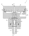
- FIG. 1 is a cross-sectional view illustrating a pressure reducing valve according to an embodiment of the present disclosure.
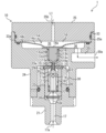
- 2 is a cross-sectional view showing a state in which a valve body is seated on a valve seat in the pressure reducing valve of FIG. 1 .
- FIG. 2 is an enlarged cross-sectional view showing the stem and the leaf spring of the pressure reducing valve of FIG. 1 .
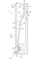
- FIG. 4 is an enlarged cross-sectional view showing an area X in the pressure reducing valve of FIG. 3 .
- FIG. FIG. 2 is a cross-sectional view showing a gas flow in the pressure reducing valve of FIG. 1 .
- the pressure reducing valve 1 according to an embodiment of the present disclosure will be described below with reference to the drawings mentioned above. Note that the concept of direction used in the following description is used for convenience in the description and does not limit the orientation of the configuration of the present disclosure to that direction. Furthermore, the pressure reducing valve 1 described below is merely one embodiment of the present disclosure. Therefore, the present disclosure is not limited to the following embodiment, and additions, deletions, and modifications are possible within the scope of the spirit of the present disclosure.
- the pressure reducing valve 1 shown in FIG. 1 is used when reducing the pressure of gases such as compressed natural gas and hydrogen gas to the operating pressure or atmospheric pressure.
- the pressure reducing valve 1 comprises a casing 10, a valve body 11, a coil spring 12, a stem 13, and a leaf spring 14.
- the casing 10, the valve body 11, the coil spring 12, the stem 13, and the leaf spring 14 are arranged along a predetermined axis L1.
- the casing 10 has a passage 15.
- the casing 10 also has an accommodation space 16.
- the casing 10 also has a primary side passage 17, a valve body chamber 18, a guide portion 19, and a secondary side passage 20.
- the primary side passage 17 has a primary port 17a, and gas is input from the primary port 17a.
- the primary side passage 17 also connects to the valve body chamber 18.
- the valve body chamber 18 connects to the guide portion 19 via the passage 15.
- the guide portion 19 connects to the secondary side passage 20 via a secondary chamber 36 of the accommodation space 16, which will be described later in detail.
- the secondary side passage 20 has a secondary port 20a, and gas flows from the secondary port 20a.
- the casing 10 includes a joint portion 21, a valve body housing 22, a seat 23, a casing body 24, and a cover 25.
- the casing 10 also includes a filter 26.
- the joint part 21 has a primary side passage 17, a housing mounting part 28, and a seat mounting part 29.
- the primary side passage 17, the housing mounting part 28, and the seat mounting part 29 are formed along the axis L1 in the joint part 21. That is, the joint part 21 is formed in a cylindrical shape, and the primary side passage 17, the housing mounting part 28, and the seat mounting part 29 form an inner hole of the joint part 21.
- the primary side passage 17, the housing mounting part 28, and the seat mounting part 29 are formed in the joint part 21 in that order from one axial end.
- a primary port 17a is formed at one axial end of the joint part 21, and the seat mounting part 29 opens at the other axial end of the joint part 21.
- the axial direction is the direction in which the axis L1 extends.
- the housing mounting part 28 is formed with a larger diameter than the primary side passage 17.
- the seat mounting part 29 is formed with a larger diameter than the housing mounting part 28.
- a pipe (not shown) is connected to one axial side portion of the joint portion 21.
- a nut is formed in the middle portion of the joint portion 21.
- a male thread is formed in the other axial side portion of the joint portion 21.
- the valve body housing 22 has the valve body 11, which will be described later in detail, inserted therethrough so as to be slidable in the axial direction.
- the valve body housing 22 is accommodated in the housing mounting portion 28 with the valve body 11 inserted therethrough.
- the valve body housing 22 is formed in a cylindrical shape.
- a filter 26 is attached to one axial end of the valve body housing 22.
- the filter 26 is attached to the valve body housing 22 so as to cover the opening on one axial side of the valve body housing 22.
- the filter 26 captures contaminants and the like contained in the gas flowing from the primary side passage 17.
- the middle portion of the inner hole of the valve body housing 22 is formed with a smaller diameter than the remaining portion.
- the inner hole of the valve body housing 22, in the other axial direction side of the middle portion forms the valve body chamber 18.
- the valve body 11 is inserted into the valve body chamber 18 so as to be slidable.
- the seat 23 is attached to the seat attachment portion 29 of the joint portion 21. More specifically, the seat 23 is fitted into the seat attachment portion 29.
- the seat 23 is formed, for example, in a circular ring shape, and has a through hole 23a.
- the through hole 23a is formed along the axis L1.
- the valve body 11 is seated on the seat 23. This closes the through hole 23a.
- the seat 23 is made of, for example, a synthetic resin. However, the seat 23 may also be made of a metal such as stainless steel.
- the casing body 24 has a joint mounting portion 30, a communication hole 31, a guide portion 19, the storage space 16, a cover mounting portion 33, and a secondary side passage 20.
- the joint mounting portion 30, the communication hole 31, the guide portion 19, the storage space 16, and the cover mounting portion 33 are formed along the axis L1.
- the joint mounting portion 30, the communication hole 31, the guide portion 19, the storage space 16, and the cover mounting portion 33 are formed in the casing body 24 in that order from one axial side.
- the joint mounting portion 30 and the cover mounting portion 33 are open at each of one and the other axial ends of the casing body 24.
- the other axial side portion of the joint part 21 is inserted and attached to the joint mounting part 30. More specifically, the joint mounting part 30 is formed with a female thread. The other axial side portion of the joint part 21 is screwed into the joint mounting part 30 in a sealed state. More specifically, the joint part 21 is attached to the seat mounting part 29 in a state where the seat 23 protrudes slightly, and is screwed into the joint mounting part 30 so that the seat 23 is pressed against the bottom of the joint mounting part 30. Note that the joint part 21 does not necessarily have to be screwed into the joint mounting part 30, and may be fixed to the joint mounting part 30 in other manners such as fastening and fitting.
- the communication hole 31 is connected to the joint mounting portion 30 and has a smaller diameter than the joint mounting portion 30. More specifically, the communication hole 31 is connected to the through hole 23a of the sheet 23 and constitutes the passage 15 together with the through hole 23a. In this embodiment, the communication hole 31 is formed with the same hole diameter as the through hole 23a.
- the guide portion 19 is connected to the communication hole 31 and has a larger diameter than the communication hole 31.
- the stem 13, which will be described in detail later, is slidably inserted into the guide portion 19, and guides the stem 13 in the axial direction.
- the accommodation space 16 is connected to the guide portion 19 and has a larger diameter than the guide portion 19.
- the accommodation space 16 is formed with a larger diameter than the joint attachment portion 30, the communication hole 31, and the guide portion 19.
- the cover attachment portion 33 is formed on the other axial side of the accommodation space 16 and has a larger diameter than the accommodation space 16. As a result, a step portion 33a is formed around the entire circumference around the opening of the accommodation space 16.
- the secondary passage 20 is formed away from the axis L1 in the radial direction outward.
- the secondary passage 20 is formed radially outward from the guide portion 19.
- the secondary passage 20 is connected to the accommodation space 16.
- the secondary passage 20 has a secondary port 20a, which opens, for example, on the side surface of the casing body 24.
- the cover 25 is attached to the cover mounting portion 33. More specifically, the cover 25 has a convex portion 25a that protrudes to one side in the axial direction. The convex portion 25a is fitted to the cover mounting portion 33 in a sealed state. This blocks the storage space 16.
- the cover 25 is fastened to the casing body 24, for example, by a fastening member (not shown).
- the cover 25 may be attached to the casing body 24 by a method other than fastening with a fastening member, for example, a screwing method in which the cover 25 is screwed into the casing body 24.
- the cover 25 also has an air vent hole 25b formed along the axis L1.
- the valve body 11 is housed in the casing 10 so as to be movable.
- the valve body 11 adjusts the opening degree of the passage 15 by changing its position according to the secondary pressure.
- the valve body 11 is a cylindrical member with a bottom. That is, the inner hole of the valve body 11 is open at one axial end.
- the tip side portion of the valve body 11 on the other axial side is formed in a tapered shape (in this embodiment, a truncated cone shape).
- a plurality of through passages 11a are formed in the tip side portion of the valve body 11. The through passages 11a extend and open from the inner hole of the valve body 11 to the side surface of the tip side portion (in this embodiment, a tapered surface).
- the one axial end side portion of the valve body 11 is recessed radially inward over the entire circumference.
- the valve body 11 is made of a metal such as stainless steel.
- the valve body 11 is molded from a synthetic resin.
- the valve body 11 may be molded from a metal.
- both the valve body 11 and the seat 23 may be molded from synthetic resin or metal.
- valve body 11 is inserted into the valve body housing 22 so as to be axially slidable.
- the inner hole of the valve body 11 is connected to the primary side passage 17 via the other axial side portion of the inner hole of the valve body housing 22 and the filter 26.
- the tip side portion of the valve body 11 is formed in a truncated cone shape as described above, and forms an annular passage 22a between the valve body housing 22 and the valve body housing 22.
- the inner hole of the valve body 11 is connected to the annular passage 22a via the through passage 11a.
- the valve body 11 seats on the seat 23 by moving in the other axial direction, which is an example of a closing direction (i.e., a direction in which the passage 15 is closed).
- valve body 11 moves in one axial direction, which is an example of an opening direction (i.e., a direction in which the passage 15 is opened), and leaves the seat 23. This opens the passage 15. This connects the annular passage 22a to the passage 15.
- the valve body 11 adjusts the opening of the passage 15 by moving toward or away from the seat 23 (i.e., moving axially).
- the coil spring 12 which is an example of a first biasing member, biases the valve body 11 in the other axial direction.
- the coil spring 12 is, for example, a compression coil spring.
- the coil spring 12 is fitted around the valve body 11. More specifically, the coil spring 12 is fitted around a recessed portion at one axial end of the valve body 11. This reduces the axial dimension of the pressure reducing valve 1.
- one end of the coil spring 12 abuts against the valve body 11, and the other end abuts against a middle portion of the valve body housing 22. This biases the valve body 11 in the other axial direction by the coil spring 12.
- the coil spring 12 does not necessarily need to be fitted around the valve body 11, and may abut against one axial end of the valve body 11.
- the stem 13 is movably housed in the casing 10 as shown in FIG. 3. More specifically, the stem 13 is slidably guided in the casing 10 in the axial direction. In this embodiment, the stem 13 is slidably inserted into the guide portion 19 of the casing body 24. The stem 13 also abuts against the valve body 11. More specifically, the stem 13 has an abutment portion 13a on one axial side (i.e., the tip side). The abutment portion 13a is formed long and thin, and protrudes from the guide portion 19 through the passage 15 into the valve body chamber 18. The abutment portion 13a is formed with a smaller diameter than the passage 15. Therefore, the gas flows around the abutment portion 13a toward the guide portion 19. The abutment portion 13a also abuts against the valve body 11 in the valve body chamber 18. In this embodiment, the tip of the abutment portion 13a abuts against the tip of the valve body 11.
- the stem 13 has a sliding portion 13b on the other axial side (i.e., the base end side).
- a plurality of communication passages 13c are formed on the outer peripheral surface of the sliding portion 13b.
- the communication passages 13c are arranged at intervals in the circumferential direction on the outer peripheral surface of the sliding portion 13b.
- the communication passages 13c may be formed on the inner peripheral surface of the guide portion 19 instead of the outer peripheral surface of the sliding portion 13b.
- the communication passages 13c extend from one end to the other end of the sliding portion 13b.
- the sliding portion 13b is fitted into the guide portion 19 so as to be axially slidable, and is guided in sliding motion in the axial direction by the guide portion 19.
- the sliding portion 13b is also disposed away from the bottom surface of the guide portion 19 in the other axial direction. Therefore, an annular passage 19a is formed between the sliding portion 13b and the bottom surface of the guide portion 19 and around the abutment portion 13a.
- the annular passage 19a is connected to the passage 15, and is also connected to the storage space 16 (more specifically, to the secondary chamber 36, which will be described later in detail) via the aforementioned multiple communication passages 13c.
- the leaf spring 14 which is an example of a second biasing member, is attached to the stem 13. In this embodiment, the leaf spring 14 abuts against the base end surface of the stem 13 as described later. However, the leaf spring 14 may be fixed to the stem 13 by welding or the like. The leaf spring 14 generates a restoring force according to the displacement. The leaf spring 14 moves the stem 13 by the generated restoring force. The leaf spring 14 biases the stem 13 in one axial direction, thereby moving the valve body 11 in one axial direction.
- the leaf spring 14 is, for example, a plate-shaped metal member (in this embodiment, a member made of SUS such as SUS304CSP or an alloy). The leaf spring 14 is a plate member that is solid and circular when viewed in the axial direction. To explain in more detail, the leaf spring 14 is formed in a convex shape in one axial direction. That is, the leaf spring 14 is formed in a convex cross section with the center portion 14a protruding in one axial direction.
- the central portion 14a of the leaf spring 14 is flat and has a larger diameter than the outer diameter of the valve body 11.
- the outer edge portion 14b of the leaf spring 14 is also flat.
- the leaf spring 14 has a tapered portion 14c that connects the outer edge portion 14b and the central portion 14a, which is formed as follows. That is, the tapered portion 14c is tapered as shown in FIG. 4. In this embodiment, the tapered portion 14c is tapered at a plurality of angles.
- the outer edge portion 14d and the central portion 14e of the tapered portion 14c have different taper angles ⁇ and ⁇ . That is, the taper angle ⁇ of the central portion 14e is more acute than the taper angle ⁇ of the outer edge portion 14d.
- the leaf spring 14 biases the valve body 11 in one axial direction via the stem 13 so as to resist the secondary pressure.
- the bias of the leaf spring 14 moves the valve body 11 in one axial direction.
- the leaf spring 14 is provided in the casing 10.
- the leaf spring 14 is housed in the accommodation space 16.
- the leaf spring 14 extends further to the side than the stem 13 when viewed in the axial direction.
- the leaf spring 14 also divides the accommodation space 16 into a secondary chamber 36 and an open space 35.
- the secondary chamber 36 is a space into which the secondary pressure is introduced, and is formed to face the leaf spring 14.
- the secondary chamber 36 is a space on one axial side of the leaf spring 14 in the accommodation space 16.
- the secondary chamber 36 is connected to the passage 15 via multiple communication passages 13c as described above.
- the secondary pressure, reduced by the valve body 11 adjusting the opening of the passage 15, is introduced into the secondary chamber 36 through the passage 15 and the multiple communication passages 13c.
- the leaf spring 14 faces the secondary chamber 36. Therefore, the leaf spring 14 receives the secondary pressure in a direction against the biasing force of the leaf spring 14.
- the secondary chamber 36 is also connected to the secondary side passage 20 as described above, and gas flows into the secondary side passage 20 through the secondary chamber 36.
- the open space 35 is located on the axially opposite side of the secondary chamber 36, sandwiching the leaf spring 14.
- the open space 35 is connected to the atmosphere via the atmospheric vent hole 25b of the cover 25.
- the open space 35 draws in and exhausts air via the atmospheric vent hole 25b. This allows the leaf spring 14 to elastically deform without increasing the internal pressure of the open space 35.
- the leaf spring 14 also seals between the open space 35 and the secondary chamber 36.
- the leaf spring 14 is provided in the casing 10 by being sandwiched between the casing body 24 and the cover 25.
- the outer edge portion 14b of the leaf spring 14 is sandwiched in a sealed state over the entire circumferential direction between the step portion 33a of the casing body 24 and the outer circumferential edge portion of the convex portion 25a of the cover 25.
- the leaf spring 14 is provided in the casing 10 so as to divide the storage space 16 into the open space 35 and the secondary chamber 36 and to seal between the open space 35 and the secondary chamber 36.
- the leaf spring 14 is formed in a convex shape in one axial direction, and the central portion 14a of the leaf spring 14 abuts against the base end surface of the stem 13.
- the stem 13 abuts against the valve body 11 as described above.
- the valve body 11 is biased in the other axial direction by the coil spring 12. Therefore, the stem 13 is pressed in the other axial direction by the valve body 11, and further the leaf spring 14 is pressed in the other axial direction by the stem 13. That is, the leaf spring 14 receives the biasing force of the coil spring 12 in the other axial direction via the valve body 11 and the stem 13.
- the leaf spring 14 biases the stem 13 in one axial direction against the biasing force of the coil spring 12, and biases the valve body 11 in one axial direction via the stem 13.
- the valve element 11 changes position according to the secondary pressure to adjust the opening of the passage 15. That is, the valve element 11 receives the biasing force of the coil spring 12 and the biasing force of the leaf spring 14 in opposing directions, and the leaf spring 14 receives the secondary pressure in the other axial direction. Therefore, the valve element 11 moves to a position where the biasing force of the coil spring 12, the biasing force of the leaf spring 14, and the secondary pressure are balanced. As a result, the valve element 11 moves to a position according to the secondary pressure to adjust the opening of the passage 15, and the secondary pressure is maintained at a predetermined pressure.
- the leaf spring 14 elastically deforms as follows. That is, in the leaf spring 14, the taper angle ⁇ of the center side portion 14e is more acute than the taper angle ⁇ of the outer edge side portion 14d. Therefore, the leaf spring 14 can move the center portion 14a parallel to the axial direction while its outer edge is clamped.
- the tapered portion 14c elastically deforms while changing the relative angle between the outer edge side portion 14d and the center side portion 14e. The tapered portion 14c then moves the center portion 14a in parallel. Therefore, the leaf spring 14 can abut the base end surface of the stem 13 and the center portion 14a in a flat state. This can prevent the stem 13 from hitting the leaf spring 14 on one side.
- the outer edge portion 14d and the center portion 14e of the tapered portion 14c do not necessarily have to have different taper angles, and may be formed with a single taper angle.
- the outer peripheral edge of the convex portion 25a protrudes to one axial side over the entire circumference.
- the convex portion 25a is recessed radially inward from the outer peripheral edge. Therefore, when the leaf spring 14 bends to the other axial side, the outer peripheral portion 14b is prevented from hitting the convex portion 25a. This makes it possible to ensure space for the leaf spring 14 to bend.
- the inner portion of the outer peripheral portion 14b can be bent toward the convex portion 25a. Therefore, the height of the leaf spring 14 in the pressure reducing valve 1 can be further reduced.
- the leaf spring 14 is a leaf-shaped spring that extends laterally from the stem 13. This allows the axial dimension of the pressure reducing valve 1 to be reduced.
- the secondary chamber 36 is formed to face the leaf spring 14. Therefore, the leaf spring 14 receives the secondary pressure in the secondary chamber 36 and moves the valve body 11 to a position according to the secondary pressure via the stem 13. This adjusts the opening of the passage 15 according to the secondary pressure.
- a compression coil spring biases the stem via a pressure receiving member, but in the pressure reducing valve 1, the leaf spring 14 can directly bias the stem 13. Therefore, the pressure receiving member that receives the secondary pressure can be omitted in the pressure reducing valve 1, and the number of parts of the pressure reducing valve 1 can be reduced.
- the leaf spring 14 divides the accommodation space 16 into an open space 35 and a secondary chamber 36, and seals between the secondary chamber 36 and the open space 35. Therefore, since the leaf spring 14 also has a sealing function, the number of parts can be reduced. This allows the pressure reducing valve 1 to be made more compact.
- the leaf spring 14 abuts against the base end surface of the stem 13. Therefore, the leaf spring 14 can be displaced relative to the stem 13. This makes it possible to prevent the stem 13 from sliding eccentrically in the casing 10. Therefore, the stem 13 can be moved smoothly.
- the leaf spring 14 is formed in a disk shape that is convex in the opening direction. Therefore, the height of the pressure reducing valve 1 can be kept low while smoothly biasing the stem 13 in the opening direction.
- the leaf spring 14 includes an outer edge portion 14b and a central portion 14a.
- the outer edge portion 14b is flat and is attached to the casing 10.
- the central portion 14a is flat and abuts against the stem 13. Therefore, the leaf spring 14 can be easily attached to the casing 10 and the stem 13.
- the leaf spring 14 has a tapered portion 14c. Therefore, when the leaf spring 14 bends, the tapered portion 14c elastically deforms while changing the relative angle between the outer edge portion 14b and the central portion 14a, and the central portion 14a can move in parallel. This allows the stem 13 to come into straight contact.
- the communication passage 13c is connected to the secondary side passage 20 via the secondary chamber 36. Therefore, the number of passages formed in the casing 10 can be reduced. This makes it possible to prevent the pressure reducing valve 1 from becoming large.
- the leaf spring 14 abuts against the valve body 11, but may be fixed to the valve body 11.
- the leaf spring 14 is not limited to the shape described above, and may have any plate shape (e.g., rectangular when viewed in the axial direction) extending laterally from the valve body 11.
- the leaf spring 14 does not necessarily have to have a pressure-receiving function or a sealing function, and these functions may be achieved by the valve body 11 or a separate member. That is, a pressure-receiving portion may be formed on the valve body 11 or the stem 13, or sealing may be achieved by using an O-ring or a diaphragm.
- the secondary chamber 36 and the secondary side passage 20 do not necessarily need to be connected, and the secondary side passage 20 may be directly connected to the annular passage 19a.
- the secondary chamber 36 may be connected to the passage 15 via the secondary side passage 20, or may be connected to the secondary side passage 20 connected to the annular passage 19a via another passage or external piping.
- multiple communication passages may be formed in the guide portion 19.
- the communication passage may be formed inside the stem 13, or may be formed in the casing body 24.
- the pressure reducing valve in the first aspect comprises a casing including a passage, a valve body movably housed in the casing and adjusting the opening of the passage, a first biasing member biasing the valve body in a closing direction, a stem movably housed in the casing and abutting the valve body, and a second biasing member biasing the valve body in an opening direction via the stem against a secondary pressure, the second biasing member being a plate-shaped spring extending laterally from the stem.
- the second biasing member is a plate-shaped spring that extends laterally from the stem. This allows the axial dimension of the pressure reducing valve to be reduced.
- the pressure reducing valve is the pressure reducing valve of the first aspect, in which the casing includes a secondary chamber to which the secondary pressure is introduced, and the secondary chamber is formed to face the second biasing member.
- the secondary chamber is formed to face the second biasing member. Therefore, the second biasing member receives the secondary pressure from the secondary chamber and moves the valve body to a position according to the secondary pressure via the stem. This adjusts the opening of the passage according to the secondary pressure. Therefore, the pressure-receiving member that receives the secondary pressure can be omitted, and the number of parts of the pressure reducing valve can be reduced.
- the pressure reducing valve of the third aspect is the pressure reducing valve of the second aspect, in which the casing includes a storage space that stores the second biasing member, and the second biasing member divides the storage space into an open space that is open to the atmosphere and the secondary chamber, and seals between the secondary chamber and the open space.
- the second biasing member divides the storage space into an open space and a secondary chamber, and seals between the secondary chamber and the open space. Therefore, since the second biasing member also has a sealing function, the number of parts can be reduced. This allows the pressure reducing valve to be made smaller.
- the pressure reducing valve is the pressure reducing valve of any one of the first to third aspects, in which the stem is arranged to be slidably guided within the casing, and the second biasing member abuts against the end face of the stem.
- the second biasing member abuts against the end face of the stem. Therefore, the second biasing member can be displaced relative to the stem. This makes it possible to prevent the stem from sliding eccentrically in the casing. Therefore, the stem can be moved smoothly.
- the pressure reducing valve is the pressure reducing valve of any one of the first to fourth aspects, in which the second biasing member is formed in a disk shape that is convex in the opening direction.
- the second biasing member is formed in a disk shape that is convex in the opening direction. Therefore, the stem can be smoothly biased in the opening direction while keeping the height of the pressure reducing valve small.
- the pressure reducing valve is the pressure reducing valve of the fifth aspect, in which the second biasing member includes an outer edge portion and a central portion, the outer edge portion of the second biasing member is flat and attached to the casing, and the central portion of the second biasing member is flat and abuts against the stem.
- the second urging member includes an outer edge portion and an intermediate portion.
- the outer edge portion is flat and is attached to the casing.
- the intermediate portion is flat and abuts against the stem. Therefore, the second urging member can be easily attached to the casing and the stem.
- the pressure reducing valve is the pressure reducing valve of the sixth aspect, in which the second biasing member includes a tapered portion connecting the outer edge portion and the central portion.
- the second biasing member has a tapered portion that connects the outer edge portion and the central portion. Therefore, when the leaf spring bends, the tapered portion elastically deforms while changing the relative angle between the outer edge portion and the central portion, and the central portion can be moved in parallel. This allows the stem to be pushed straight.
- the pressure reducing valve in the eighth aspect is the pressure reducing valve in the second or third aspect, in which the casing includes a guide portion that slides and guides the stem, and a secondary side passage that is connected to a secondary port, and at least one of the guide portion and the stem has a communication passage that is connected to the secondary chamber, and the communication passage is connected to the secondary side passage via the secondary chamber.
- the communication passage is connected to the secondary passage via the secondary chamber. This makes it possible to reduce the number of passages formed in the casing. This makes it possible to prevent the pressure reducing valve from becoming too large.
Landscapes
- Engineering & Computer Science (AREA)
- General Engineering & Computer Science (AREA)
- Physics & Mathematics (AREA)
- Mechanical Engineering (AREA)
- Fluid Mechanics (AREA)
- General Physics & Mathematics (AREA)
- Automation & Control Theory (AREA)
- Control Of Fluid Pressure (AREA)
Abstract
通路を含むケーシングと、ケーシングに移動可能に収容され、通路の開度を調整する弁体と、閉方向に弁体を付勢する第1付勢部材と、移動可能にケーシングに収容され、弁体に当接するステムと、ステムを介して、二次圧に抗するように開方向へ弁体を付勢する第2付勢部材と、を備え、第2付勢部材は、板状のばねであってステムより側方に延在している、減圧弁。
Description
本開示は、ガスを減圧して出力する減圧弁に関する。
圧縮天然ガス及び水素ガス等のガスに関する減圧弁として、例えば特許文献1のような減圧弁が知られている。特許文献1の減圧弁では、圧縮コイルばねの付勢力と二次圧とが互いに抗するようにピストンに作用している。ピストンは、二次圧に応じた力で弁体を押すことによって弁通路の開度を調整する。
特許文献1の減圧弁では、圧縮コイルばねによってピストンを付勢しているので、減圧弁のサイズ、特に軸線方向の長さが大きくなる。
そこで本開示は、小型化することができる減圧弁を提供することを目的としている。
本開示の減圧弁は、通路を含むケーシングと、前記ケーシングに移動可能に収容され、前記通路の開度を調整する弁体と、閉方向に前記弁体を付勢する第1付勢部材と、移動可能に前記ケーシングに収容され、前記弁体に当接するステムと、前記ステムを介して、二次圧に抗するように開方向へ前記弁体を付勢する第2付勢部材と、を備え、前記第2付勢部材は、板状のばねであって前記ステムより側方に延在しているものである。
本開示の減圧弁に従えば、第2付勢部材は、ステムより側方に延在している板状のばねである。それ故、減圧弁の軸方向の寸法を小さくすることができる。
本開示によれば、小型化することができる。
本開示の上記目的、他の目的、特徴、及び利点は、添付図面参照の下、以下の好適な実施態様の詳細な説明から明らかにされる。
以下、本開示に係る実施形態の減圧弁1について前述する図面を参照しながら説明する。なお、以下の説明で用いる方向の概念は、説明する上で便宜上使用するものであって、本開示の構成の向き等をその方向に限定するものではない。また、以下に説明する減圧弁1は、本開示の一実施形態に過ぎない。従って、本開示は以下の実施形態に限定されず、本開示の趣旨を逸脱しない範囲で追加、削除、変更が可能である。
図1に示す減圧弁1は、圧縮天然ガス及び水素ガス等のガスの圧力を使用圧力又は大気圧まで減圧する場合に用いられている。減圧弁1は、ケーシング10と、弁体11と、コイルばね12と、ステム13と、板ばね14とを備えている。本実施形態の減圧弁1では、所定の軸線L1に沿ってケーシング10と、弁体11と、コイルばね12と、ステム13と、板ばね14とが配置されている。
<ケーシング>
ケーシング10は、通路15を有している。また、ケーシング10は、収容空間16を有している。更に、ケーシング10は、一次側通路17と、弁体室18と、ガイド部19と、二次側通路20と、を有している。一次側通路17は、一次ポート17aを有しており、一次ポート17aからガスが入力される。また、一次側通路17は、弁体室18に繋がっている。弁体室18は、通路15を介してガイド部19に繋がっている。ガイド部19は、後で詳述する収容空間16の二次室36を介して二次側通路20に繋がっている。二次側通路20は、二次ポート20aを有しており、二次ポート20aからガスを流す。更に詳細に説明すると、ケーシング10は、継手部21と、弁体ハウジング22と、シート23と、ケーシング本体24と、カバー25とを含んでいる。また、ケーシング10は、フィルター26とを含んでいる。
ケーシング10は、通路15を有している。また、ケーシング10は、収容空間16を有している。更に、ケーシング10は、一次側通路17と、弁体室18と、ガイド部19と、二次側通路20と、を有している。一次側通路17は、一次ポート17aを有しており、一次ポート17aからガスが入力される。また、一次側通路17は、弁体室18に繋がっている。弁体室18は、通路15を介してガイド部19に繋がっている。ガイド部19は、後で詳述する収容空間16の二次室36を介して二次側通路20に繋がっている。二次側通路20は、二次ポート20aを有しており、二次ポート20aからガスを流す。更に詳細に説明すると、ケーシング10は、継手部21と、弁体ハウジング22と、シート23と、ケーシング本体24と、カバー25とを含んでいる。また、ケーシング10は、フィルター26とを含んでいる。
継手部21は、一次側通路17と、ハウジング取付部28と、シート取付部29と、を有している。一次側通路17、ハウジング取付部28、及びシート取付部29は、継手部21において軸線L1に沿って形成されている。即ち、継手部21は円筒状に形成され、一次側通路17、ハウジング取付部28、及びシート取付部29は、継手部21の内孔を形成している。また、一次側通路17、ハウジング取付部28、及びシート取付部29は、軸方向一方側からその順で継手部21に形成されている。そして、継手部21の軸方向一端に一次ポート17aが形成され、継手部21の軸方向他端においてシート取付部29が開口している。なお、軸方向は、軸線L1が延在する方向である。また、ハウジング取付部28は、一次側通路17より大径に形成されている。シート取付部29は、ハウジング取付部28より大径に形成されている。また、継手部21の軸方向一方側部分には、例えば図示しない配管が接続される。継手部21の中間部分には、ナットが形成されている。また、継手部21の軸方向他方側部分には、雄ねじが形成されている。
弁体ハウジング22は、後で詳述する弁体11が軸方向に摺動可能に挿通されている。弁体ハウジング22は、弁体11を挿通させた状態でハウジング取付部28に収容されている。更に詳細に説明すると、弁体ハウジング22は、円筒状に形成されている。弁体ハウジング22の軸方向一端には、フィルター26が取り付けられている。フィルター26は、弁体ハウジング22の軸方向一方側の開口を覆うように弁体ハウジング22に取り付けられている。フィルター26は、一次側通路17から流れるガスに含まれるコンタミ等を捕捉する。また、弁体ハウジング22の内孔は、中間部分が残余部分より小径に形成されている。そして、弁体ハウジング22の内孔において、中間部分より軸方向他方側の部分が弁体室18を成している。弁体室18には、弁体11が摺動可能に挿通されている。
シート23は、継手部21のシート取付部29に取り付けられている。より詳細に説明すると、シート23は、シート取付部29に嵌り込んでいる。シート23は、例えば円環状に形成されており、貫通孔23aを有している。貫通孔23aは、軸線L1に沿って形成されている。シート23には、弁体11が着座する。これにより、貫通孔23aが閉じられる。シート23は、例えば合成樹脂から成る。但し、シート23は、ステンレス鋼等の金属であってもよい。
ケーシング本体24は、継手取付部30と、連通孔31と、ガイド部19と、収容空間16と、カバー取付部33と、二次側通路20とを有している。継手取付部30、連通孔31、ガイド部19,収容空間16、及びカバー取付部33は、軸線L1に沿って形成されている。より詳細に説明すると、継手取付部30、連通孔31、ガイド部19、収容空間16、及びカバー取付部33は、軸方向一方側からその順でケーシング本体24に形成されている。そして、ケーシング本体24の軸方向一端及び他端の各々において、継手取付部30及びカバー取付部33が開口している。
継手取付部30には、継手部21の軸方向他方側部分が挿入されて取り付けられている。より詳細に説明すると、継手取付部30は、雌ねじが形成されている。継手取付部30には、継手部21の軸方向他方側部分がシールを達成した状態で螺合されている。更に詳細に説明すると、継手部21には、シート23が僅かに突き出た状態でシート取付部29に取り付けられており、シート23を継手取付部30の底に押し当てるように継手取付部30に螺合されている。なお、継手部21は、必ずしも継手取付部30に螺合されている必要はなく、締結及び嵌合等のその他の態様で継手取付部30に固定されてもよい。
連通孔31は、継手取付部30に繋がっており、継手取付部30より小径に形成されている。より詳細に説明すると、連通孔31は、シート23の貫通孔23aに繋がっており、貫通孔23aと共に通路15を構成している。なお、連通孔31は、本実施形態において貫通孔23aと同じ孔径で形成されている。
ガイド部19は、連通孔31に繋がっており、連通孔31より大径に形成されている。ガイド部19は、後で詳述するステム13が摺動可能に挿入され、ステム13を軸方向に摺動案内する。収容空間16は、ガイド部19に繋がっており、ガイド部19より大径に形成されている。本実施形態において、収容空間16は、継手取付部30、連通孔31、及びガイド部19より大径に形成されている。カバー取付部33は、収容空間16の軸方向他方側に形成されており、収容空間16より大径に形成されている。これにより、収容空間16の開口の周りには、全周にわたって段部33aが形成されている。
二次側通路20は、軸線L1から径方向外方に離して形成されている。本実施形態において、二次側通路20は、ガイド部19の径方向外方に形成されている。二次側通路20は、収容空間16に繋がっている。また、二次側通路20は、前述の通り、二次ポート20aを有しており、二次ポート20aは、例えばケーシング本体24の側面にて開口している。
カバー25は、カバー取付部33に取り付けられている。より詳細に説明すると、カバー25は、軸方向一方側に突出する凸状部25aを有している。凸状部25aは、シールを達成した状態でカバー取付部33に嵌合されている。これにより、収容空間16が塞がれている。また、カバー25は、例えば図示しない締結部材によってケーシング本体24に締結されている。なお、カバー25は、締結部材による締結以外の方法、例えばカバー25をケーシング本体24に螺合するようなねじ込み方式でケーシング本体24に設けられてもよい。カバー25の軸方向一端面、即ち凸状部25aの端面では、外周縁部が周方向全周にわたって軸方向一方側に突出している。また、カバー25には、軸線L1に沿って大気開放孔25bが形成されている。
<弁体>
弁体11は、ケーシング10に移動可能に収容されている。また、弁体11は、二次圧に応じて位置を変えて通路15の開度を調整する。弁体11は、本実施形態において有底円筒部材である。即ち、弁体11の内孔は、軸方向一端において開口している。また、弁体11の軸方向他方側にある先端側部分は、テーパ状(本実施形態において円錐台状)に形成されている。更に、弁体11の先端側部分には、複数の貫通路11aが形成されている。貫通路11aは、弁体11の内孔から先端側部分の側面(本実施形態において、テーパ面)まで延在して開口している。また、弁体11の軸方向一端側部分は、周方向全周にわたって径方向内方に凹んでいる。また、弁体11は、ステンレス鋼等の金属から成る。但し、弁体11は、シート23がステンレス鋼等の金属から成る場合、合成樹脂によって成形されている。なお、弁体11は、シート23が合成樹脂から成る場合、金属によって成形されていてもよい。また、弁体11及びシート23が共に合成樹脂、又は金属によって成形されてもよい。
弁体11は、ケーシング10に移動可能に収容されている。また、弁体11は、二次圧に応じて位置を変えて通路15の開度を調整する。弁体11は、本実施形態において有底円筒部材である。即ち、弁体11の内孔は、軸方向一端において開口している。また、弁体11の軸方向他方側にある先端側部分は、テーパ状(本実施形態において円錐台状)に形成されている。更に、弁体11の先端側部分には、複数の貫通路11aが形成されている。貫通路11aは、弁体11の内孔から先端側部分の側面(本実施形態において、テーパ面)まで延在して開口している。また、弁体11の軸方向一端側部分は、周方向全周にわたって径方向内方に凹んでいる。また、弁体11は、ステンレス鋼等の金属から成る。但し、弁体11は、シート23がステンレス鋼等の金属から成る場合、合成樹脂によって成形されている。なお、弁体11は、シート23が合成樹脂から成る場合、金属によって成形されていてもよい。また、弁体11及びシート23が共に合成樹脂、又は金属によって成形されてもよい。
弁体11は、前述の通り弁体ハウジング22に軸方向に摺動可能に挿通されている。弁体11の内孔は、弁体ハウジング22の内孔の軸方向他方側の部分及びフィルター26を介して一次側通路17に繋がっている。弁体11の先端側部分は、前述の通り円錐台状に形成されており、弁体ハウジング22との間に環状通路22aを形成している。弁体11の内孔は、貫通路11aを介して環状通路22aに繋がっている。また、弁体11は、図2に示すように閉方向(即ち、通路15を閉じる方向)の一例である軸方向他方に移動することによってシート23に着座する。これにより、通路15が閉じられる。他方、弁体11は、開方向(即ち、通路15を開く方向)の一例である軸方向一方に移動することによってシート23から離れる。これにより、通路15が開かれる。これにより、環状通路22aが通路15と繋がる。そして、弁体11は、シート23に対して近づいたり離れたりする(即ち、軸方向に移動する)ことによって通路15の開度を調整する。
<コイルばね>
第1付勢部材の一例であるコイルばね12は、軸方向他方に弁体11を付勢する。コイルばね12は、例えば圧縮コイルバネである。コイルばね12は、弁体11に外装されている。より詳細に説明すると、コイルばね12は、弁体11の軸方向一端側部分であって凹んでいる部分に外装されている。これにより、減圧弁1の軸方向寸法が抑えられている。また、コイルばね12の一端は弁体11に当接し、他端は弁体ハウジング22の中間部分に当接している。これにより、弁体11は、コイルばね12によって軸方向他方に付勢されている。なお、コイルばね12は、必ずしも弁体11に外装されている必要はなく、弁体11の軸方向一端に当接しててもよい。
第1付勢部材の一例であるコイルばね12は、軸方向他方に弁体11を付勢する。コイルばね12は、例えば圧縮コイルバネである。コイルばね12は、弁体11に外装されている。より詳細に説明すると、コイルばね12は、弁体11の軸方向一端側部分であって凹んでいる部分に外装されている。これにより、減圧弁1の軸方向寸法が抑えられている。また、コイルばね12の一端は弁体11に当接し、他端は弁体ハウジング22の中間部分に当接している。これにより、弁体11は、コイルばね12によって軸方向他方に付勢されている。なお、コイルばね12は、必ずしも弁体11に外装されている必要はなく、弁体11の軸方向一端に当接しててもよい。
ステム13は、図3に示すようにケーシング10に移動可能に収容されている。より詳細に説明すると、ステム13は、ケーシング10において軸方向に摺動案内されている。本実施形態において、ステム13は、ケーシング本体24のガイド部19に摺動可能に挿通されている。また、ステム13は、弁体11に当接している。より詳細に説明すると、ステム13は、軸方向一方側(即ち、先端側)に当接部13aを有している。当接部13aは、細長く形成されており、ガイド部19から通路15を通って弁体室18に突き出ている。当接部13aは、通路15より小径に形成されている。それ故、ガスは、当接部13aの周りを通ってガイド部19の方へと流れる。また、当接部13aは、弁体室18にある弁体11に当接している。本実施形態において、当接部13aの先端が弁体11の先端に当接している。
他方、ステム13は、軸方向他方側(即ち、基端側)に摺動部13bを有している。摺動部13bには、外周面に複数の連通路13cが形成されている。連通路13cは、摺動部13bの外周面において周方向に間隔をあけて配置されている。なお、連通路13cは、摺動部13bの外周面に代えてガイド部19の内周面に形成されていてもよい。また、連通路13cは、摺動部13bの一端から他端まで延在している。
摺動部13bは、ガイド部19に軸方向に摺動可能に嵌り込ませ、ガイド部19によって軸方向に摺動案内されている。また、摺動部13bは、ガイド部19の底面から軸方向他方に離れて配置されている。それ故、摺動部13bとガイド部19の底面との間であって当接部13aの周りには、環状通路19aが形成されている。環状通路19aは、通路15に繋がり、また前述する複数の連通路13cを介して収容空間16(より詳細に説明すると、後で詳述する二次室36)に繋がっている。
第2付勢部材の一例である板ばね14は、ステム13に取り付けられている。本実施形態において、板ばね14は、後述するようにステム13の基端面に当接している。但し、板ばね14は、ステム13に溶接等によって固定されてもよい。板ばね14は、変位に応じた復元力を発生する。そして、板ばね14は、発生する復元力によってステム13を移動させる。板ばね14は、ステム13を軸方向一方に付勢することによって弁体11を軸方向一方に移動させる。板ばね14は、例えば板状の金属製の部材(本実施形態においてSUS304CSP等のSUS製及び合金製の部材)である。板ばね14は、軸方向に見て中実円形状状の板部材である。より詳細に説明すると、板ばね14は、軸方向一方に凸状に形成されている。即ち、板ばね14は、中心部分14aが軸線方向一方に突出する断面凸状に形成されている。
更に詳細に説明すると、板ばね14の中心部分14aは、弁体11の外径より大径で且つフラット状になっている。また、板ばね14の外縁部分14bもフラット状になっている。更に、板ばね14は、外縁部分14bと中心部分14aとを繋ぐテーパ部14cが以下のように形成されている。即ち、テーパ部14cは、図4に示すようにテーパ状に形成されている。本実施形態では、テーパ部14cは複数の角度のテーパ状に形成されている。詳細に説明すると、テーパ部14cは外縁側部分14dと中心側部分14eとが互いに異なるテーパ角α,βを有している。即ち、中心側部分14eのテーパ角βは、外縁側部分14dのテーパ角αより鋭角になっている。
板ばね14は、ステム13を介して、二次圧に抗するように軸方向一方に弁体11を付勢する。板ばね14は、付勢することによって弁体11を軸方向一方に移動させる。板ばね14は、ケーシング10に設けられている。より詳細に説明すると、板ばね14は、収容空間16に収容されている。板ばね14は、軸方向に見てステム13より更に側方に延在している。また、板ばね14は、収容空間16を二次室36と開放空間35とに分割している。
二次室36は、二次圧が導かれる空間であって、板ばね14に面するように形成されている。本実施形態において、二次室36は、収容空間16において板ばね14より軸方向一方側の空間である。二次室36は、前述の通り複数の連通路13cを介して通路15に繋がっている。そして、二次室36には、弁体11が通路15の開度を調整することによって減圧された二次圧が通路15及び複数の連通路13cを通って導かれる。板ばね14は、二次室36に面している。それ故、板ばね14は、板ばね14の付勢力に抗する方向に二次圧を受圧している。また、二次室36は、前述の通り二次側通路20と繋がっており、ガスが二次室36を通って二次側通路20に流れる。
開放空間35は、板ばね14を挟んで二次室36の軸方向反対側に位置している。開放空間35は、カバー25の大気開放孔25bを介して大気に繋がっている。開放空間35は、大気開放孔25bを介して空気を吸排する。これにより、開放空間35の内圧を高めることなく板ばね14の弾性変形が許容される。
また、板ばね14は、開放空間35と二次室36との間をシールしている。より詳細に説明すると、板ばね14は、ケーシング本体24とカバー25とに挟持されることによってケーシング10に設けられている。本実施形態において、板ばね14の外縁部分14bが、周方向全周にわたってケーシング本体24の段部33aとカバー25の凸状部25aの外周縁部とにシールされた状態で挟持されている。これにより、板ばね14は、収容空間16を開放空間35と二次室36とに分割し且つ開放空間35と二次室36との間をシールするようにケーシング10に設けられている。
また、板ばね14は、前述の通り、軸線方向一方に凸状に形成されており、板ばね14の中心部分14aがステム13の基端面に当接している。ステム13は、前述の通り弁体11に当接している。また、弁体11は、コイルばね12によって軸方向他方に付勢されている。それ故、ステム13は、弁体11によって軸方向他方に押され、更にステム13によって板ばね14が軸方向他方に押される。即ち、板ばね14は、弁体11及びステム13を介してコイルばね12の付勢力を軸方向他方に受けている。そして、板ばね14は、コイルばね12の付勢力に抗してステム13を軸方向一方に付勢し、ステム13を介して弁体11を軸方向一方に付勢している。
<減圧弁の動作>
減圧弁1では、図5の矢印Aに示すように一次ポート17aから一次圧のガスが流入する。流入したガスは、一次側通路17を通ってフィルター26に導かれる。フィルター26では、ガスに含まれるコンタミが捕捉される。その後、ガスは、弁体ハウジング22の弁体室18に導かれ、更に弁体11の内孔及び複数の貫通路11aを通って環状通路22aに導かれる。更に、ガスは、環状通路22aから通路15を通って環状通路19aに導かれる。通路15の開度は、弁体11によって調整されている。これにより、二次圧は通路15の開度に応じた圧力に調整される。また、ガスは、環状通路19aから複数の連通路13cを通って二次室36に導かれ、更に二次室36から二次側通路20を通って二次ポート20aから流出する。
減圧弁1では、図5の矢印Aに示すように一次ポート17aから一次圧のガスが流入する。流入したガスは、一次側通路17を通ってフィルター26に導かれる。フィルター26では、ガスに含まれるコンタミが捕捉される。その後、ガスは、弁体ハウジング22の弁体室18に導かれ、更に弁体11の内孔及び複数の貫通路11aを通って環状通路22aに導かれる。更に、ガスは、環状通路22aから通路15を通って環状通路19aに導かれる。通路15の開度は、弁体11によって調整されている。これにより、二次圧は通路15の開度に応じた圧力に調整される。また、ガスは、環状通路19aから複数の連通路13cを通って二次室36に導かれ、更に二次室36から二次側通路20を通って二次ポート20aから流出する。
このようにガスが流れる減圧弁1では、弁体11が二次圧に応じて位置を変えて通路15の開度を調整する。即ち、弁体11は、互いに抗する方向にコイルばね12の付勢力及び板ばね14の付勢力を受けており、更に板ばね14は、二次圧を軸方他方に受圧している。それ故、弁体11は、コイルばね12の付勢力、板ばね14の付勢力、及び二次圧が釣り合う位置へと移動する。これにより、弁体11が二次圧に応じた位置へと移動して通路15の開度を調整し、二次圧が所定圧に保たれる。
この際、板ばね14は、以下のように弾性変形する。即ち、板ばね14では、中心側部分14eのテーパ角βが外縁側部分14dのテーパ角αより鋭角になっている。それ故、板ばね14は、その外縁が挟持された状態で中心部分14aを軸方向に平行に移動させることができる。より詳細に説明すると、板ばね14では、テーパ部14cが外縁側部分14d及び中心側部分14eの相対角を変えながら弾性変形する。そして、テーパ部14cは、中心部分14aを平行に移動させる。それ故、板ばね14は、ステム13の基端面と中心部分14aとを互いにフラットな状態で当接させることができる。これにより、ステム13が板ばね14に対して片当たりすることを抑制できる。なお、テーパ部14cは、必ずしも外縁側部分14dと中心側部分14eとが互いに異なるテーパ角を有している必要はなく、1つのテーパ角にて形成されていてもよい。
また、カバー25では、凸状部25aにおいて外周縁部が周方向全周にわたって軸方向一方側に突出している。即ち、凸状部25aにおいて、外周縁部より径方向内側が凹んでいる。それ故、板ばね14が軸方向他方側に撓む際に外縁部分14bが凸状部25aに当たることが抑制される。これにより、板ばね14が撓むためのスペースを確保することができる。即ち、外縁部分14bの内側部分を凸状部25aの方に撓ませることができる。それ故、減圧弁1における板ばね14の高さを更に抑えることができる。
本実施形態の減圧弁1において、板ばね14は、ステム13より側方に延在している板状のばねである。それ故、減圧弁1の軸方向の寸法を小さくすることができる。
また、本実施形態の減圧弁1において、二次室36は、板ばね14に面するように形成されている。それ故、板ばね14は、二次室36に二次圧を受圧し、ステム13を介して弁体11を二次圧に応じた位置へと移動させる。これにより、二次圧に応じて通路15の開度が調整される。従来の減圧弁では、圧縮コイルばねが受圧部材を介してステムを付勢しているが、減圧弁1では板ばね14によってステム13を直接付勢することができる。従って、減圧弁1において二次圧を受圧する受圧部材を省略することができ、減圧弁1の部品点数を低減することができる。
更に、本実施形態の減圧弁1において、板ばね14は、収容空間16を開放空間35と二次室36とに分割し且つ二次室36と開放空間35との間をシールする。従って、板ばね14がシール機能も有しているので、部品点数を低減することができる。これにより、減圧弁1を小型化することができる。
更に、本実施形態の減圧弁1において、板ばね14は、ステム13の基端面に当接している。それ故、板ばね14は、ステム13に対して相対変位することができる。これにより、ケーシング10において、ステム13が偏心して摺動することを抑制することができる。従って、ステム13を円滑に動かすことができる。
更に、本実施形態の減圧弁1において、板ばね14は、開方向に凸状の円板状に形成されている。それ故、減圧弁1の高さを抑えつつ円滑にステム13を開方向に付勢することができる。
更に、本実施形態の減圧弁1において、板ばね14は、外縁部分14bと中心部分14aとを含む。外縁部分14bがフラット状であってケーシング10に取り付けられている。中心部分14aがフラット状であってステム13に当接している。それ故、板ばね14は、ケーシング10及びステム13に容易に取り付けることができる。
更に、本実施形態の減圧弁1において、板ばね14は、テーパ部14cを有している。それ故、板ばね14が撓む際、テーパ部14cが外縁部分14b及び中心部分14aとの相対角を変えながら弾性変形し、中心部分14aを平行に移動させることができる。これにより、ステム13を真っ直ぐ当接させることができる。
更に、本実施形態の減圧弁1において、連通路13cは、二次室36を介して二次側通路20に繋がっている。それ故、ケーシング10に形成される通路の数を抑えることができる。これにより、減圧弁1が大きくなることを抑制することができる。
[その他の実施形態]
本実施形態において、板ばね14は、弁体11に当接しているが、弁体11に固定されていてもよい。また、板ばね14は、前述するような形状に限定されず、弁体11から側方に延在する板形状(例えば、軸方向に見て矩形状)のものであればよい。また、板ばね14は、必ずしも受圧機能やシール機能を有している必要はなく、弁体11及び別部材によって達成するようにしてもよい。即ち、弁体11又はステム13に受圧部が形成されたり、Oリング又はダイアフラムを用いてシールが達成されたりしてもよい。
本実施形態において、板ばね14は、弁体11に当接しているが、弁体11に固定されていてもよい。また、板ばね14は、前述するような形状に限定されず、弁体11から側方に延在する板形状(例えば、軸方向に見て矩形状)のものであればよい。また、板ばね14は、必ずしも受圧機能やシール機能を有している必要はなく、弁体11及び別部材によって達成するようにしてもよい。即ち、弁体11又はステム13に受圧部が形成されたり、Oリング又はダイアフラムを用いてシールが達成されたりしてもよい。
また、二次室36と二次側通路20とは必ずしもつながっている必要はなく、二次側通路20が環状通路19aに直接繋がっていてもよい。また、二次室36は、二次側通路20を介して通路15に繋がっていてもよく、環状通路19aに繋がる二次側通路20に他の通路又は外部配管を介して繋がっていてもよい。また、二次室36へ二次圧を導くべくステム13に必ずしも連通路13cが形成されている必要はない。例えば、ガイド部19に複数の連通路が形成されていてもよい。また、連通路は、ステム13の内部に形成されていてもよく、ケーシング本体24に形成されていてもよい。
第1の局面における減圧弁は、通路を含むケーシングと、前記ケーシングに移動可能に収容され、前記通路の開度を調整する弁体と、閉方向に前記弁体を付勢する第1付勢部材と、移動可能に前記ケーシングに収容され、前記弁体に当接するステムと、前記ステムを介して、二次圧に抗するように開方向へ前記弁体を付勢する第2付勢部材と、を備え、前記第2付勢部材は、板状のばねであって前記ステムより側方に延在している。
上記局面に従えば、第2付勢部材は、ステムより側方に延在している板状のばねである。それ故、減圧弁の軸方向の寸法を小さくすることができる。
第2の局面における減圧弁は、第1の局面の減圧弁において、前記ケーシングは、二次圧が導かれる二次室を含み、前記二次室は、前記第2付勢部材に面するように形成されている。
上記局面に従えば、二次室は、第2付勢部材に面するように形成されている。それ故、第2付勢部材は、二次室から二次圧を受圧し、ステムを介して弁体を二次圧に応じた位置へと移動させる。これにより、二次圧に応じて通路の開度が調整される。従って、二次圧を受圧する受圧部材を省略することができ、減圧弁の部品点数を低減することができる。
第3の局面における減圧弁は、第2の局面の減圧弁において、前記ケーシングは、前記第2付勢部材を収容する収容空間を含み、前記第2付勢部材は、大気に開放される開放空間と前記二次室とに前記収容空間を分割し、且つ前記二次室と前記開放空間との間をシールする。
上記局面に従えば、第2付勢部材は、収容空間を開放空間と二次室とに分割し且つ二次室と開放空間との間をシールする。従って、第2付勢部材がシール機能も有しているので、部品点数を低減することができる。これにより、減圧弁を小型化することができる。
第4の局面における減圧弁は、第1乃至3の何れかの局面の減圧弁において、前記ステムは、前記ケーシング内において摺動案内されるように配置され、前記第2付勢部材は、前記ステムの端面に当接している。
上記局面に従えば、第2付勢部材は、ステムの端面に当接している。それ故、第2付勢部材は、ステムに対して相対変位することができる。これにより、ケーシングにおいてステムが偏心して摺動することを抑制することができる。従って、ステムを円滑に動かすことができる。
第5の局面における減圧弁は、第1乃至4の何れかの局面の減圧弁において、前記第2付勢部材は、開方向に凸状の円板状に形成されている。
上記局面に従えば、第2付勢部材は、開方向に凸状の円板状に形成されている。それ故、減圧弁の高さを抑えつつ円滑にステムを開方向に付勢することができる。
第6の局面における減圧弁は、第5の局面の減圧弁において、前記第2付勢部材は、外縁部分と中心部分とを含み、前記第2付勢部材の外縁部分は、フラット状であって前記ケーシングに取り付けられ、前記第2付勢部材の中心部分は、フラット状であって前記ステムに当接している。
上記局面に従えば、第2付勢部材は、外縁部分と中間部分とを含む。外縁部分がフラット状であってケーシングに取り付けられている。中間部分がフラット状であってステムに当接している。それ故、第2付勢部材は、ケーシング及びステムに容易に取り付けることができる。
第7の局面における減圧弁は、第6の局面の減圧弁において、前記第2付勢部材は、前記外縁部分と前記中心部分とを繋ぐテーパ部を含む。
上記局面に従えば、第2付勢部材は、外縁部分と中心部分とを繋ぐテーパ部を有している。それ故、板ばねが撓む際、テーパ部が外縁部分及び中心部分との相対角を変えながら弾性変形し、中心部分を平行に移動させることができる。これにより、ステムを真っ直ぐ押すことができる。
第8の局面における減圧弁は、第2又は3の局面の減圧弁において、前記ケーシングは、前記ステムを摺動案内するガイド部と、二次ポートに繋がる二次側通路とを含み、前記ガイド部及び前記ステムの少なくとも一方には、前記二次室に繋がる連通路が形成され、前記連通路は、前記二次室を介して前記二次側通路に繋がっている。
上記局面に従えば、連通路は、二次室を介して二次側通路に繋がっている。それ故、ケーシングに形成される通路の数を抑えることができる。これにより、減圧弁が大きくなることを抑制することができる。
上記説明から、当業者にとっては、本開示の多くの改良や他の実施形態が明らかである。従って、上記説明は、例示としてのみ解釈されるべきであり、本開示を実行する最良の態様を当業者に教示する目的で提供されたものである。本開示の精神を逸脱することなく、その構造及び/又は機能の詳細を実質的に変更できる。
1 減圧弁
10 ケーシング
11 弁体
12 コイルばね(第1付勢部材)
13 ステム
13c 連通路
14 板ばね(第2付勢部材)
14a 中心部分
14b 外縁部分
14c テーパ部
15 通路
16 収容空間
19 ガイド部
20 二次側通路
35 開放空間
36 二次室
10 ケーシング
11 弁体
12 コイルばね(第1付勢部材)
13 ステム
13c 連通路
14 板ばね(第2付勢部材)
14a 中心部分
14b 外縁部分
14c テーパ部
15 通路
16 収容空間
19 ガイド部
20 二次側通路
35 開放空間
36 二次室
Claims (8)
- 通路を含むケーシングと、
前記ケーシングに移動可能に収容され、前記通路の開度を調整する弁体と、
閉方向に前記弁体を付勢する第1付勢部材と、
移動可能に前記ケーシングに収容され、前記弁体に当接するステムと、
前記ステムを介して、二次圧に抗するように開方向へ前記弁体を付勢する第2付勢部材と、を備え、
前記第2付勢部材は、板状のばねであって前記ステムより側方に延在している、減圧弁。 - 前記ケーシングは、二次圧が導かれる二次室を含み、
前記二次室は、前記第2付勢部材に面するように形成されている、請求項1に記載の減圧弁。 - 前記ケーシングは、前記第2付勢部材を収容する収容空間を含み、
前記第2付勢部材は、大気に開放される開放空間と前記二次室とに前記収容空間を分割し、且つ前記二次室と前記開放空間との間をシールする、請求項2に記載の減圧弁。 - 前記ステムは、前記ケーシング内において摺動案内されるように配置され、
前記第2付勢部材は、前記ステムの端面に当接している、請求項1に記載の減圧弁。 - 前記第2付勢部材は、開方向に凸状の円板状に形成されている、請求項1に記載の減圧弁。
- 前記第2付勢部材は、外縁部分と中心部分とを含み、
前記第2付勢部材の外縁部分は、フラット状であって前記ケーシングに取り付けられ、
前記第2付勢部材の中心部分は、フラット状であって前記ステムに当接している、請求項5に記載の減圧弁。 - 前記第2付勢部材は、前記外縁部分と前記中心部分とを繋ぐテーパ部を含む、請求項6に記載の減圧弁。
- 前記ケーシングは、前記ステムを摺動案内するガイド部と、二次ポートに繋がる二次側通路とを含み、
前記ガイド部及び前記ステムの少なくとも一方には、前記二次室に繋がる連通路が形成され、
前記連通路は、前記二次室を介して前記二次側通路に繋がっている、請求項2に記載の減圧弁。
Priority Applications (2)
| Application Number | Priority Date | Filing Date | Title |
|---|---|---|---|
| JP2025529665A JP7880014B2 (ja) | 2023-06-27 | 2024-06-18 | 減圧弁 |
| CN202480041935.6A CN121399555A (zh) | 2023-06-27 | 2024-06-18 | 减压阀 |
Applications Claiming Priority (2)
| Application Number | Priority Date | Filing Date | Title |
|---|---|---|---|
| JP2023105160 | 2023-06-27 | ||
| JP2023-105160 | 2023-06-27 |
Publications (1)
| Publication Number | Publication Date |
|---|---|
| WO2025004906A1 true WO2025004906A1 (ja) | 2025-01-02 |
Family
ID=93938999
Family Applications (1)
| Application Number | Title | Priority Date | Filing Date |
|---|---|---|---|
| PCT/JP2024/022076 Ceased WO2025004906A1 (ja) | 2023-06-27 | 2024-06-18 | 減圧弁 |
Country Status (3)
| Country | Link |
|---|---|
| JP (1) | JP7880014B2 (ja) |
| CN (1) | CN121399555A (ja) |
| WO (1) | WO2025004906A1 (ja) |
Citations (3)
| Publication number | Priority date | Publication date | Assignee | Title |
|---|---|---|---|---|
| US4637439A (en) * | 1981-02-09 | 1987-01-20 | Cadbury Schweppes, Plc | Mini-regulator valve assembly |
| JPH06309042A (ja) * | 1993-04-20 | 1994-11-04 | Motoyama Seisakusho:Kk | 減圧弁 |
| JP2021124130A (ja) * | 2020-01-31 | 2021-08-30 | 川崎重工業株式会社 | 減圧弁、バルブユニット、弁装置、及び板ばね |
Family Cites Families (1)
| Publication number | Priority date | Publication date | Assignee | Title |
|---|---|---|---|---|
| JP7104530B2 (ja) | 2018-03-13 | 2022-07-21 | Kyb株式会社 | ソレノイド、電磁弁、及び緩衝器 |
-
2024
- 2024-06-18 CN CN202480041935.6A patent/CN121399555A/zh active Pending
- 2024-06-18 WO PCT/JP2024/022076 patent/WO2025004906A1/ja not_active Ceased
- 2024-06-18 JP JP2025529665A patent/JP7880014B2/ja active Active
Patent Citations (3)
| Publication number | Priority date | Publication date | Assignee | Title |
|---|---|---|---|---|
| US4637439A (en) * | 1981-02-09 | 1987-01-20 | Cadbury Schweppes, Plc | Mini-regulator valve assembly |
| JPH06309042A (ja) * | 1993-04-20 | 1994-11-04 | Motoyama Seisakusho:Kk | 減圧弁 |
| JP2021124130A (ja) * | 2020-01-31 | 2021-08-30 | 川崎重工業株式会社 | 減圧弁、バルブユニット、弁装置、及び板ばね |
Also Published As
| Publication number | Publication date |
|---|---|
| CN121399555A (zh) | 2026-01-23 |
| JP7880014B2 (ja) | 2026-06-24 |
| JPWO2025004906A1 (ja) | 2025-01-02 |
Similar Documents
| Publication | Publication Date | Title |
|---|---|---|
| TWI825291B (zh) | 流體控制閥 | |
| CN102156490B (zh) | 减压流体调节器 | |
| CN103097785A (zh) | 用于流体阀的阀座装置 | |
| US10989317B2 (en) | Two-way valve | |
| CN104685278B (zh) | 流体控制器用执行机构 | |
| EP3008353B1 (en) | Actuator bushings having integral seals | |
| CN102365599B (zh) | 减压阀 | |
| US20070257219A1 (en) | Double diaphragm actuator | |
| CN114867958B (zh) | 减压阀、阀单元、阀装置及板簧 | |
| JP4506496B2 (ja) | 減圧弁 | |
| CN111609188A (zh) | 减压阀 | |
| LU500908B1 (en) | Pressure regulator for compressed gas with adjustable gas pressure sensing assembly | |
| US7418973B2 (en) | Device to reduce noise in pressure regulators | |
| CN121399555A (zh) | 减压阀 | |
| JP2019199926A (ja) | 弁装置 | |
| JP7819339B2 (ja) | 減圧弁、及び弁装置 | |
| US10823295B2 (en) | Device for controlling fluid flow | |
| US20260043494A1 (en) | Valve trim apparatus for use with fluid valves | |
| CN104797997B (zh) | 控制阀 | |
| JP2024135061A (ja) | レギュレータ | |
| JP2024090101A (ja) | 圧力調整弁 | |
| JP2022019228A (ja) | 圧力調整弁 | |
| JP2022092791A (ja) | 減圧弁 | |
| CN113357413A (zh) | 压力调节阀 | |
| US20110284788A1 (en) | High Performance Miniature Regulator |
Legal Events
| Date | Code | Title | Description |
|---|---|---|---|
| 121 | Ep: the epo has been informed by wipo that ep was designated in this application |
Ref document number: 24831768 Country of ref document: EP Kind code of ref document: A1 |
|
| WWE | Wipo information: entry into national phase |
Ref document number: 2025529665 Country of ref document: JP |
|
| NENP | Non-entry into the national phase |
Ref country code: DE |
|
| 122 | Ep: pct application non-entry in european phase |
Ref document number: 24831768 Country of ref document: EP Kind code of ref document: A1 |