WO2025004869A1 - 冷却用熱交換器 - Google Patents
冷却用熱交換器 Download PDFInfo
- Publication number
- WO2025004869A1 WO2025004869A1 PCT/JP2024/021765 JP2024021765W WO2025004869A1 WO 2025004869 A1 WO2025004869 A1 WO 2025004869A1 JP 2024021765 W JP2024021765 W JP 2024021765W WO 2025004869 A1 WO2025004869 A1 WO 2025004869A1
- Authority
- WO
- WIPO (PCT)
- Prior art keywords
- metal plate
- cooling
- heat exchanger
- resin member
- divided bodies
- Prior art date
- Legal status (The legal status is an assumption and is not a legal conclusion. Google has not performed a legal analysis and makes no representation as to the accuracy of the status listed.)
- Ceased
Links
Images




Classifications
-
- H—ELECTRICITY
- H01—ELECTRIC ELEMENTS
- H01M—PROCESSES OR MEANS, e.g. BATTERIES, FOR THE DIRECT CONVERSION OF CHEMICAL ENERGY INTO ELECTRICAL ENERGY
- H01M10/00—Secondary cells; Manufacture thereof
- H01M10/60—Heating or cooling; Temperature control
- H01M10/61—Types of temperature control
- H01M10/613—Cooling or keeping cold
-
- H—ELECTRICITY
- H01—ELECTRIC ELEMENTS
- H01M—PROCESSES OR MEANS, e.g. BATTERIES, FOR THE DIRECT CONVERSION OF CHEMICAL ENERGY INTO ELECTRICAL ENERGY
- H01M10/00—Secondary cells; Manufacture thereof
- H01M10/60—Heating or cooling; Temperature control
- H01M10/62—Heating or cooling; Temperature control specially adapted for specific applications
- H01M10/625—Vehicles
-
- H—ELECTRICITY
- H01—ELECTRIC ELEMENTS
- H01M—PROCESSES OR MEANS, e.g. BATTERIES, FOR THE DIRECT CONVERSION OF CHEMICAL ENERGY INTO ELECTRICAL ENERGY
- H01M10/00—Secondary cells; Manufacture thereof
- H01M10/60—Heating or cooling; Temperature control
- H01M10/65—Means for temperature control structurally associated with the cells
- H01M10/655—Solid structures for heat exchange or heat conduction
- H01M10/6554—Rods or plates
-
- H—ELECTRICITY
- H01—ELECTRIC ELEMENTS
- H01M—PROCESSES OR MEANS, e.g. BATTERIES, FOR THE DIRECT CONVERSION OF CHEMICAL ENERGY INTO ELECTRICAL ENERGY
- H01M10/00—Secondary cells; Manufacture thereof
- H01M10/60—Heating or cooling; Temperature control
- H01M10/65—Means for temperature control structurally associated with the cells
- H01M10/655—Solid structures for heat exchange or heat conduction
- H01M10/6556—Solid parts with flow channel passages or pipes for heat exchange
-
- H—ELECTRICITY
- H05—ELECTRIC TECHNIQUES NOT OTHERWISE PROVIDED FOR
- H05K—PRINTED CIRCUITS; CASINGS OR CONSTRUCTIONAL DETAILS OF ELECTRIC APPARATUS; MANUFACTURE OF ASSEMBLAGES OF ELECTRICAL COMPONENTS
- H05K7/00—Constructional details common to different types of electric apparatus
- H05K7/20—Modifications to facilitate cooling, ventilating, or heating
-
- H—ELECTRICITY
- H10—SEMICONDUCTOR DEVICES; ELECTRIC SOLID-STATE DEVICES NOT OTHERWISE PROVIDED FOR
- H10W—GENERIC PACKAGES, INTERCONNECTIONS, CONNECTORS OR OTHER CONSTRUCTIONAL DETAILS OF DEVICES COVERED BY CLASS H10
- H10W40/00—Arrangements for thermal protection or thermal control
- H10W40/40—Arrangements for thermal protection or thermal control involving heat exchange by flowing fluids
- H10W40/47—Arrangements for thermal protection or thermal control involving heat exchange by flowing fluids by flowing liquids, e.g. forced water cooling
Definitions
- the present invention relates to a cooling heat exchanger that is installed in, for example, an electric vehicle or a hybrid vehicle, and that cools an object to be cooled, such as a battery pack.
- Cooling units for cooling heat-generating elements such as batteries installed in electric vehicles, hybrid vehicles, etc. have been proposed in the past, and such cooling units are described, for example, in International Publication No. 2020/196878 (Patent Document 1).
- Patent Document 1 describes first to sixth embodiments of the cooling unit, but all of the embodiments include a metal plate-shaped lid that is placed over the object to be cooled (e.g., a battery cell) and a resin box with a flow path for allowing the refrigerant to flow inside.
- the opening of a groove provided in the box is covered by the plate-shaped lid, forming a cooling flow path for the refrigerant to flow.
- the present invention was made against the background of the above-mentioned circumstances, and the problem to be solved is to provide a new cooling heat exchanger that combines metal components and synthetic resin components, which can prevent distortion of the cooling heat exchanger even in high-temperature environments, for example, and also makes it possible to improve manufacturing efficiency.
- the first aspect is a cooling heat exchanger in which a metal plate that is placed on the object to be cooled and a plate-shaped resin member with a groove are placed on top of each other and fixed to each other, and the opening of the groove is covered with the metal plate to form a cooling flow path through which a heat medium flows between the metal plate and the resin member, and the resin member is divided into a plurality of segments, each of which is placed on top of and fixed to the metal plate, adjacent segments are separated from each other, and the spaces between the segments form bulge-permitting sections that allow the segments to bulge and deform.
- the resin member has a divided structure consisting of multiple divided bodies, and the gap between adjacent divided bodies forms an expansion-permitting portion that allows the divided bodies to expand and deform.
- the expansion-permitting portion suppresses distortion of the cooling heat exchanger due to the expansion and deformation of the resin member, which is particularly susceptible to influence.
- the larger the joint area between the metal plate and the resin member the larger the distortion of the cooling heat exchanger due to the difference in the linear expansion coefficient between the metal plate and the resin member tends to be.
- the resin member can be used as a relatively small divided body, it is possible to improve the ease of handling of the resin member (each divided body) and the manufacturing efficiency when manufacturing the cooling heat exchanger.
- the adjacent divided bodies are arranged at a predetermined interval in the longitudinal direction of the metal plate.
- adjacent segments are spaced apart from each other in the longitudinal direction of the metal plate, which prevents each segment from becoming excessively elongated compared to, for example, a case in which adjacent segments are spaced apart from each other in the lateral direction of the metal plate, thereby further improving the ease of handling of each segment and the manufacturing efficiency when manufacturing the cooling heat exchanger.
- the present invention provides a cooling heat exchanger that can prevent distortion even in high-temperature environments and can also improve manufacturing efficiency.
- FIG. 1 is a perspective view of a cooling heat exchanger according to an embodiment of the present invention
- FIG. 2 is a perspective view of the cooling heat exchanger shown in FIG. 1 from the bottom side.
- FIG. 2 is an enlarged longitudinal sectional view of the III-III section in FIG.
- FIG. 2 is an exploded perspective view of the cooling heat exchanger shown in FIG. 1 .
- FIG. 2 is a perspective view showing a metal plate constituting the cooling heat exchanger shown in FIG. 1 .
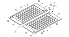
- FIG. 2 is a perspective view showing a resin member constituting the cooling heat exchanger shown in FIG. 1 .
- FIGs 1 to 4 show a cooling heat exchanger 10 as one embodiment of the present invention.
- This cooling heat exchanger 10 is installed in, for example, an electric vehicle or a hybrid vehicle, and is superimposed on an object to be cooled 12 (shown by a two-dot chain line in Figure 3) such as a battery pack that generates heat in the electric vehicle or hybrid vehicle, to cool the object to be cooled 12.
- the up-down direction generally refers to the up-down direction in Figure 3.
- a metal plate 14 that is placed on the object to be cooled 12 and a plate-shaped resin member 18 with a groove 16 are placed on top of each other and fixed together, and the opening (upper opening 20) of the groove 16 is covered by the metal plate 14, thereby forming a cooling flow path 22 through which a heat transfer medium (refrigerant) flows between the metal plate 14 and the resin member 18.
- a heat transfer medium heat transfer medium
- the metal plate 14 is preferably made of a metal with excellent thermal conductivity, such as copper (including copper alloys) or aluminum (including aluminum alloys).
- the metal plate 14 is made of aluminum.
- the metal plate 14 is a substantially rectangular plate, and the four peripheral sides are composed of a pair of long sides 24, 24 and a pair of short sides 26, 26 connecting the long sides 24.
- the thickness of the metal plate 14 is not limited, but in this embodiment, it is made relatively thin.
- the metal plate 14 has through holes 28 formed therethrough in the thickness direction at positions corresponding to the inlet portion 38 and the outlet portion 40 of the overlapping resin member 18 (each divided body 30, 30 described later).
- a pair of through holes 28, 28 are provided spaced apart at both ends in the direction in which the long side 24 extends, and at the other end portion (upper right portion in FIG. 5) in the direction in which the short side 26 extends, a pair of through holes 28, 28 are provided spaced apart at the center portion in the direction in which the long side 24 extends, so that four through holes 28 are formed in one metal plate 14.
- the resin member 18 is made of a hard synthetic resin, and may be made of, for example, a fiber-reinforced synthetic resin. As shown in FIG. 6 and other figures, the resin member 18 is generally rectangular plate-shaped overall, and has a certain plate thickness. Here, the resin member 18 is divided into a plurality of divided bodies 30, and in this embodiment, it is composed of two divided bodies 30, 30. The outer shapes of the divided bodies 30 are generally the same, and the divided bodies 30 are arranged adjacent to each other and spaced apart. The gaps between these divided bodies 30 are expansion allowance portions 32 that allow the expansion deformation of each divided body 30, as described below.
- adjacent segments 30 are spaced apart at a predetermined interval (expansion allowance portion 32) in the longitudinal direction (direction in which long side 24 extends) of metal plate 14.
- each segment 30 i.e., resin member 18
- each segment 30 does not protrude outward beyond metal plate 14 in its entirety. That is, each segment 30 is formed to be smaller than the metal plate 14 divided in half in the direction in which long side 24 extends, and in each segment 30, the direction in which long side 24 extends in metal plate 14 is the short direction, and the direction in which short side 26 extends in metal plate 14 is the long direction.
- Each partition 30 has a groove 16 that opens upward (has an upper opening 20).
- the grooves 16 formed in each partition 30 are similar in shape, and in this embodiment in particular, the grooves 16 in adjacent partitions 30 are symmetrical in shape. Therefore, in the following description, the groove 16 in one partition 30 will be described, and the groove 16 in the other partition 30 will be given the same reference numeral in the figures and will not be described.
- the groove 16 is formed with a depth that does not penetrate the partition 30 in the plate thickness direction (vertical direction), and is a bottomed groove shape.
- the shape of the groove 16 is not limited, but the groove 16 of this embodiment has a plurality of parallel passages 34 extending parallel to the short side 26 of the metal plate 14. Between adjacent passages 34, 34 in the parallel direction of the passages 34, a partition 35 extending parallel to the short side 26 of the metal plate 14 is provided. The upper surface of each partition 35 is at the same vertical position as the upper surface of the portion of the partition 30 where the groove 16 is not formed. Also, each passage 34 (each partition 35) is formed with a relatively long length dimension in the longitudinal direction of each partition 30 (the direction in which the short side 26 extends in the metal plate 14).
- each cooling flow path 22 in each partition 30 is formed so that the longitudinal direction is the direction in which the short side 26 extends in the metal plate 14 as a whole, and the transverse direction is the direction in which the long side 24 extends in the metal plate 14. Since each cooling flow path 22 is formed by covering each groove 16 with the metal plate 14, the area including each cooling flow path 22 (each groove 16) is the flow path forming area in the entire resin member 18, and the flow path forming area in the entire resin member 18 is formed with the direction in which the long side 24 of the metal plate 14 extends as the longitudinal direction and the direction in which the short side 26 of the metal plate 14 extends as the transverse direction. Therefore, in this embodiment, each divided body 30 is arranged at a predetermined interval in the longitudinal direction of the flow path forming area in the entire resin member 18.
- the passages 34 are connected at both ends in the longitudinal direction of each passage 34 by a connecting passage 36 extending in a direction perpendicular to the longitudinal direction of each passage 34 (parallel to the long side 24 of the metal plate 14).
- the outermost passage 34 in the parallel direction of each passage 34 extends beyond the connecting passage 36 on one side in the longitudinal direction
- the inlet portion 38 and the outlet portion 40 are formed by the portion of each outermost passage 34 in the parallel direction that extends beyond the connecting passage 36.
- the positions of the inlet portion 38 and the outlet portion 40 are not limited, but in this embodiment, the inlet portion 38 is formed in the lower left of the groove 16 in FIG. 6, and the outlet portion 40 is formed in the upper right of FIG. 6.
- a metal plate 14 is placed on each divided body 30 having the above structure, and each divided body 30 is fixed to the metal plate 14.
- the method of fixing each divided body 30 to the metal plate 14 is not limited, but for example, they are fixed by adhesion or welding, and the openings of each groove 16 (upper openings 20) are liquid-tightly sealed by the metal plate 14.
- the upper surface of the part of each divided body 30 where each groove 16 is not formed and the upper surface of each partition portion 35 are placed on the metal plate 14, thereby covering the upper openings 20 of each passage 34 and each connecting passage 36 to form a tunnel-like passage.
- each tunnel-shaped passage is interconnected to form a cooling flow path 22 through which the refrigerant flows.
- through holes 28 are formed in the metal plate 14 at positions corresponding to the inlet 38 and the outlet 40, respectively, and the cooling flow path 22 is connected to the external space through these through holes 28. That is, the inlet 38 and the through holes 28 provided at the positions corresponding to the inlet 38 form an inlet 42 that allows the refrigerant to flow from the outside into the cooling flow path 22, and the outlet 40 and the through holes 28 provided at the positions corresponding to the outlet 40 form an outlet 44 that allows the refrigerant to flow out of the cooling flow path 22 to the outside.
- the refrigerant flowing through the cooling flow passage 22 is not limited, but may be chiller water used in chillers (cooling water circulation systems) conventionally installed in vehicles, and specifically may be water, alcohol (methanol, ethanol, etc.), glycol, etc.
- the refrigerant source for the refrigerant flowing through the cooling flow passage 22 is not limited, but may be a separate chiller including a pump (not shown), or may be a chiller already installed in the vehicle. By using a chiller including a pump as the refrigerant source, the refrigerant can be caused to flow within the cooling flow passage 22.
- a heat generating body such as a battery pack, that generates heat when electricity is applied is placed on the surface (upper surface) of the metal plate 14 opposite to the surface on which the resin member 18 is superimposed.
- an inlet tube 46 connected to a pair of inlets 42, 42 is provided on the upper surface of the metal plate 14, and one end of the inlet tube 46 extends to the outside of the cooling heat exchanger 10 and is connected to a refrigerant source (not shown).
- an outlet tube 48 is connected to a pair of outlets 44, 44, and one end of the outlet tube 48 extends to the outside of the cooling heat exchanger 10 and is connected to a refrigerant source (not shown).
- a circulation system is configured in the cooling heat exchanger 10, in which the refrigerant that flows from the refrigerant source through the inlet tube 46 flows into each cooling flow path 22 from each inlet 42, flows through each cooling flow path 22, and then returns to the refrigerant source through each outlet 44 and the outlet tube 48.
- the inlet and outlet tubes 46, 48 are provided at positions on the upper surface of the metal plate 14 that are outside the cooling target 12. Therefore, in this embodiment, one cooling flow path 22 extending from the inlet 42 to the outlet 44 is provided in each divided body 30, and a pair of cooling flow paths 22, 22 are provided in parallel in the cooling heat exchanger 10.
- the subject to be cooled 12 when a heat generating body (subject to be cooled 12) such as a battery pack is placed on the metal plate 14, the subject to be cooled 12 generates heat, and the heat generated in the subject to be cooled 12 is transferred to the metal plate 14.
- the heat transferred to the metal plate 14 is cooled (heat exchanged) by the refrigerant flowing in each cooling flow path 22, preventing the temperature of the subject to be cooled 12 and the metal plate 14 from rising. Meanwhile, the refrigerant that flows into the cooling flow path 22 from each inlet 42 is heated as it flows through the cooling flow path 22, and flows out of each outlet 44 at a higher temperature than when it flowed in from each inlet 42, and reaches a refrigerant source (not shown). In this refrigerant source, the refrigerant is cooled again, and flows into the cooling flow path 22 through each inlet 42.
- the temperature of the refrigerant rises, and the temperature of the resin member 18 (each divided body 30) constituting each cooling flow path 22 also rises.
- the temperature of the cooling heat exchanger 10 rises when the vehicle is exposed to a high-temperature environment.
- the difference in linear expansion coefficient between the metal plate 14, which is a metal member, and the resin member 18 (each divided body 30), which is a synthetic resin member is relatively large, and the resin member 18 (each divided body 30) expands more than the metal plate 14.
- the resin member 18 is composed of each divided body 30, and an expansion allowance portion 32 is provided between each divided body 30.
- the expansion deformation of each divided body 30 is permitted by the expansion allowance portion 32, and even if each divided body 30 expands and deforms, contact between each divided body 30 is avoided, and distortion between the metal plate 14 and the resin member 18 (each divided body 30) can be avoided.
- the resin member 18 in particular, by making the resin member 18 into each relatively small divided body 30 rather than one large member, the resin member 18 (each divided body 30) can be handled more easily, which can improve the manufacturing efficiency of the cooling heat exchanger 10.
- adjacent segments 30 are spaced apart at a predetermined interval in the longitudinal direction of the metal plate 14 (the direction in which the long sides 24 extend). This prevents the segments from becoming excessively elongated in a plan view, compared to when the segments are arranged side by side in the short direction of the metal plate, for example, and further improves the ease of handling of the segments 30 and the manufacturing efficiency of the cooling heat exchanger 10.
- the cooling channels 22 in each divided body 30 are arranged in parallel, but this is not limited to this. That is, the cooling channels in each divided body may be connected in series by connecting the outlet in one divided body to the inlet in the other divided body.
- the two in the lower left of the metal plate 14 in FIG. 1 are inlets 42, 42, and the two in the upper right of FIG. 1 are outlets 44, 44, but this is not limited to this, and the two in the upper right of FIG. 1 may be the inlet and outlet, respectively, and these may be connected with tubes or the like to connect the two cooling channels in series as described above.
- the metal plate 14 is provided with the through holes 28, and the inlets 42 and outlets 44 open upward to connect the inlet and outlet tubes 46, 48 above the metal plate 14, but this is not limited to the above embodiment. That is, for example, through holes may be provided in the bottom wall portion constituting each inlet and outlet portion of each divided body, and the inlet and outlet may be opened downward to connect the inlet and outlet tubes below the resin member (each divided body). Alternatively, through holes may be provided in the peripheral wall portion constituting each inlet and outlet portion, and the inlet and outlet may be opened to the side to connect the inlet and outlet tubes to the side of the resin member (each divided body).
- each groove 16 includes a plurality of parallel passages 34 and a connecting passage 36 that connects each of the passages 34, but this is not limited to the above.
- the opening (upper opening) of the groove is covered with a metal plate to form a cooling flow path, and the direction of extension, length, width, depth, and other aspects of the cooling flow path can be set as desired.
- cooling efficiency heat exchange efficiency
- each divided body 30 and each groove 16 are approximately the same, but this is not limited to the above.
- Each divided body may have a different shape or size, and the shapes of each groove (each cooling flow passage) provided in each divided body may be different.
- the resin member 18 is divided into two divided bodies 30, 30, and the divided bodies 30 are arranged side by side in the direction in which the longitudinal direction (long side 24) of the metal plate 14 extends, but this is not limited to this embodiment.
- the resin member may be divided into three or more divided bodies, and the divided bodies may be arranged side by side in the short direction instead of or in addition to the longitudinal direction of the metal plate.
- three or more divided bodies it is not necessary for all the spaces between the divided bodies to be bulging allowance portions, and it is sufficient that at least one of the spaces between the divided bodies is bulging allowance portion.
- the width dimension of the bulging allowance portion 32 (the separation distance between the divided bodies 30) is set to a size such that the divided bodies 30 do not come into contact with each other when the divided bodies 30 bulge and deform, but the width dimension of the bulging allowance portion may be set to a size such that the divided bodies come into slight contact with each other when the divided bodies 30 bulge and deform, so that distortion does not occur in the cooling heat exchanger.
- one inlet tube 46 is connected to each inlet 42, 42, but a separate inlet tube may be connected to each inlet.
- one outlet tube 48 is connected to each outlet 44, 44, but a separate outlet tube may be connected to each outlet.
- Cooling heat exchanger 12 Cooling target 14: Metal plate 16: Groove 18: Resin member 20: Upper opening (opening) 22 Cooling flow passage 24 Long side 26 Short side 28 Through hole 30 Divided body 32 Expansion allowance portion 34 Passage 35 Partition portion 36 Connection passage 38 Inlet portion 40 Outlet portion 42 Inlet port 44 Outlet port 46 Inlet tube 48 Outlet tube
Landscapes
- Engineering & Computer Science (AREA)
- Manufacturing & Machinery (AREA)
- Chemical & Material Sciences (AREA)
- Chemical Kinetics & Catalysis (AREA)
- Electrochemistry (AREA)
- General Chemical & Material Sciences (AREA)
- Physics & Mathematics (AREA)
- Thermal Sciences (AREA)
- Microelectronics & Electronic Packaging (AREA)
- Cooling Or The Like Of Electrical Apparatus (AREA)
- Cooling Or The Like Of Semiconductors Or Solid State Devices (AREA)
- Secondary Cells (AREA)
- Cooling, Air Intake And Gas Exhaust, And Fuel Tank Arrangements In Propulsion Units (AREA)
Abstract
金属製の部材と合成樹脂製の部材とを組み合わせた冷却用熱交換器において、例えば高温環境下でも冷却用熱交換器の歪みを防止することができると共に、製造効率の向上を図ることのできる、新規な冷却用熱交換器を提供する。 冷却対象12に重ね合わされる金属プレート14と、凹溝16を備えた板状の樹脂部材18とが、相互に重ね合わされて固着されており、金属プレート14で凹溝16の開口20が覆われることによって金属プレート14と樹脂部材18の間に熱媒体が流動する冷却流路22が形成された冷却用熱交換器10であって、樹脂部材18が複数の分割体30に分割されて、それら分割体30が何れも金属プレート14に重ね合わされて固着されており、隣り合う分割体30が相互に離れており、それら分割体30の間がそれら分割体30の膨出変形を許容する膨出許容部32とされている。
Description
本発明は、例えば電気自動車やハイブリッド自動車等に設けられて、バッテリーパック等の冷却対象を冷却する冷却用熱交換器に関するものである。
従来から、電気自動車やハイブリッド自動車等に搭載される電池等の発熱体を冷却するための冷却ユニットが提案されており、かかる冷却ユニットが、例えば国際公開第2020/196878号(特許文献1)に挙げられている。
特許文献1では冷却ユニットについて第一~第六実施形態まで記載されているものの、何れの実施形態においても冷却対象である被冷却体(例えば、電池セル)に重ね合わされる金属製の板状蓋体と内部に冷媒を流動させるための流路を備えた樹脂製の箱体とを備えており、箱体に設けられた凹溝の開口が板状蓋体により覆われることで冷媒が流動するための冷却流路が構成されている。
ところで、金属製の部材と合成樹脂製の部材とは線膨張係数の差が比較的大きく、両部材に熱が加えられた際には、金属製の部材に比して合成樹脂製の部材の方が膨張し易かった。それ故、特許文献1に記載のような冷却ユニットでは、例えば発熱体(被冷却体)の発熱によって、又は車両が高温環境下に晒されること等によって、金属製の部材よりも合成樹脂製の部材の方が大きく膨張して冷却ユニットが歪み、冷却ユニットから冷媒が漏れ出すおそれがあった。また、それぞれ1つの大きな金属製の部材と合成樹脂製の部材を利用する場合、取扱性や製造効率が低下するおそれがあった。
本発明は上述の如き事情を背景としてなされたものであって、その解決課題とするところは、金属製の部材と合成樹脂製の部材とを組み合わせた冷却用熱交換器において、例えば高温環境下でも冷却用熱交換器の歪みを防止することができると共に、製造効率の向上を図ることも可能になる、新規な冷却用熱交換器を提供することにある。
以下、本発明を把握するための好ましい態様について記載するが、以下に記載の各態様は、例示的に記載したものであって、適宜に互いに組み合わせて採用され得るだけでなく、各態様に記載の複数の構成要素についても、可能な限り独立して認識及び採用することができ、適宜に別の態様に記載の何れかの構成要素と組み合わせて採用することもできる。それによって、本発明では、以下に記載の態様に限定されることなく、種々の別態様が実現され得る。
第一の態様は、冷却対象に重ね合わされる金属プレートと、凹溝を備えた板状の樹脂部材とが、相互に重ね合わされて固着されており、該金属プレートで該凹溝の開口が覆われることによって該金属プレートと該樹脂部材の間に熱媒体が流動する冷却流路が形成された冷却用熱交換器であって、前記樹脂部材が複数の分割体に分割されて、それら分割体が何れも前記金属プレートに重ね合わされて固着されており、隣り合う該分割体が相互に離れており、それら分割体の間がそれら分割体の膨出変形を許容する膨出許容部とされているものである。
本態様によれば、樹脂部材が複数の分割体による分割構造とされており、隣り合う分割体間の隙間により分割体の膨出変形を許容する膨出許容部が構成されている。これにより、例えば冷却用熱交換器が高温環境下に晒される等して比較的大きな温度変化が及ぼされた場合には、金属プレート及び樹脂部材が膨出変形するものの、特に影響を与え易い樹脂部材の膨出変形による冷却用熱交換器の歪みの抑制が膨出許容部によって実現される。詳述すると、金属プレートと樹脂部材との接合面積が大きくなるほど、金属プレートと樹脂部材の線膨張係数の差に起因する冷却用熱交換器の歪みは大きくなる傾向がある。本態様によれば、複数の樹脂部材の間に金属プレートと固着されていない膨出許容部を設けることにより、この膨出許容部において冷却用熱交換器の歪みの発生が抑制されることになる。それ故、高温環境下においても、樹脂部材の膨出変形によって冷却用熱交換器に歪みが生じることが防止される。また、樹脂部材が比較的小さな分割体として利用できることから、樹脂部材(各分割体)の取扱性や冷却用熱交換器を製造する際の製造効率の向上を図ることができる。
第二の態様は、前記第一の態様に係る冷却用熱交換器において、隣り合う前記分割体は、前記金属プレートの長手方向で、所定の間隔を空けて設けられているものである。
本態様によれば、隣り合う分割体が金属プレートの長手方向で相互に離隔していることから、例えば隣り合う分割体が金属プレートの短手方向で相互に離隔している場合と比べて各分割体が過度に細長くなることが回避され、各分割体の取扱性や冷却用熱交換器を製造する際の製造効率の更なる向上が図られる。
本発明によれば、高温環境下においても歪みを防止することのできると共に、製造効率の向上を図ることもできる、冷却用熱交換器を提供することができる。
以下、本発明を更に具体的に明らかにするために、本発明の実施形態について、図面を参照しつつ、詳細に説明する。
先ず、図1~4には、本発明の一実施形態としての冷却用熱交換器10が示されている。この冷却用熱交換器10は、例えば電気自動車やハイブリッド自動車等に設けられて、電気自動車やハイブリッド自動車等において熱を発生する電池パック等の冷却対象12(図3において二点鎖線で図示)に重ね合わされて、冷却対象12を冷却するものである。なお、以下の説明において、上下方向とは、原則として、図3中の上下方向をいう。
より詳細には、冷却用熱交換器10においては、冷却対象12に重ね合わされる金属プレート14と、凹溝16を備えた板状の樹脂部材18とが相互に重ね合わされて固着されており、金属プレート14で凹溝16の開口(上方開口部20)が覆われることによって金属プレート14と樹脂部材18の間に熱媒体(冷媒)が流動する冷却流路22が形成されている。
金属プレート14は、熱伝導性に優れる金属により形成されることが好適であり、例えば銅(銅合金を含む)やアルミニウム(アルミニウム合金を含む)により形成される。本実施形態では、金属プレート14がアルミニウムにより形成されている。特に、本実施形態では、図5等にも示されるように、金属プレート14が一枚の略矩形板状であり、周囲の四辺は、一対の長辺24,24とこれら各長辺24を接続する一対の短辺26,26とから構成されている。金属プレート14の板厚寸法は限定されるものではないが、本実施形態では、比較的薄い板厚寸法とされている。
また、金属プレート14には、重ね合わされる樹脂部材18(後述する各分割体30,30)における流入部38及び流出部40に対応する位置において、金属プレート14を板厚方向で貫通する貫通孔28が形成されている。本実施形態では、金属プレート14における短辺26の延びる方向の一方の端部分(図5中の左下部分)において、長辺24の延びる方向の両端部に一対の貫通孔28,28が相互に離隔して設けられていると共に、短辺26の延びる方向の他方の端部分(図5中の右上部分)において、長辺24の延びる方向の中央部分に一対の貫通孔28,28が相互に離隔して設けられており、一枚の金属プレート14において4つの貫通孔28が形成されている。
樹脂部材18は、硬質の合成樹脂により形成されており、例えば繊維補強された合成樹脂により形成されてもよい。樹脂部材18は、図6等にも示されるように、全体では略矩形板状であり、ある程度の板厚寸法を有している。ここにおいて、樹脂部材18は、複数の分割体30に分割されており、本実施形態では、2つの分割体30,30により構成されている。各分割体30の外形状は相互に略同形状であり、各分割体30が隣り合った状態で相互に離れて配置されている。これら各分割体30間の隙間が、後述するように各分割体30の膨出変形を許容する膨出許容部32とされている。なお、膨出許容部32において、各分割体30間の隙間の寸法(金属プレート14の長辺24方向における各分割体30間の離隔距離)は限定されるものではなく、例えば各分割体30において想定される膨出変形量を考慮して設定される。
本実施形態では、相互に隣り合う各分割体30が、金属プレート14の長手方向(長辺24の延びる方向)で所定の間隔(膨出許容部32)を空けて設けられている。特に、本実施形態では、各分割体30が金属プレート14に重ね合わされて固着された際に、各分割体30(即ち、樹脂部材18)の全体が、金属プレート14よりも外方に突出しないようになっている。即ち、各分割体30は、金属プレート14を長辺24の延びる方向で二分したものよりも小さな大きさで形成されており、各分割体30では、金属プレート14において長辺24の延びる方向が短手方向とされていると共に、金属プレート14において短辺26の延びる方向が長手方向とされている。
そして、各分割体30には、上方に開口する(上方開口部20を有する)凹溝16が形成されている。本実施形態では、各分割体30に形成される凹溝16が相互に同様の形状であり、特に本実施形態では、隣り合う各分割体30における凹溝16が相互に対称な形状とされている。それ故、以下の説明では、一方における分割体30の凹溝16について説明して、他方における分割体30の凹溝16については、図中に同一の符号を付すことにより説明を省略する。凹溝16は、分割体30を板厚方向(上下方向)で貫通しない深さ寸法で形成されており、有底の溝形状とされる。
凹溝16の形状は限定されるものではないが、本実施形態の凹溝16は、金属プレート14の短辺26と平行に延びる複数の通路34を並列的に有している。これら各通路34の並列方向において隣り合う通路34,34間には、金属プレート14の短辺26と平行に延びる仕切部35が設けられている。なお、各仕切部35の上面は、分割体30における凹溝16が形成されていない部分の上面と等しい上下方向位置にある。また、各通路34(各仕切部35)は、各分割体30の長手方向(金属プレート14において短辺26の延びる方向)において比較的長い長さ寸法をもって形成されている。そして、各分割体30における凹溝16(冷却流路22)は、全体として金属プレート14において短辺26の延びる方向を長手方向とすると共に、金属プレート14において長辺24の延びる方向を短手方向として形成されている。なお、各凹溝16が金属プレート14により覆蓋されることで各冷却流路22が構成されることから、各冷却流路22(各凹溝16)を併せた領域が樹脂部材18全体における流路形成領域であり、樹脂部材18全体における流路形成領域は、金属プレート14における長辺24の延びる方向を長手方向として、金属プレート14における短辺26の延びる方向を短手方向として形成される。それ故、本実施形態では、各分割体30が、樹脂部材18全体における流路形成領域の長手方向で所定の間隔を空けて配置されている。
そして、各通路34は、各通路34の長さ方向の両端部において、各通路34の長さ方向に直交する方向(金属プレート14の長辺24と平行)に延びる接続通路36により接続されている。特に、本実施形態では、各通路34の並列方向における最も外側の各通路34は、長さ方向の一方において接続通路36を越えて延び出しており、並列方向の最も外側の各通路34において接続通路36を越えて延び出した部分により流入部38及び流出部40が形成されている。流入部38及び流出部40の位置は限定されるものではないが、本実施形態では、凹溝16における図6中の左下部に流入部38が形成されていると共に、図6中の右上部に流出部40が形成されている。
以上のような構造とされた各分割体30に上方から金属プレート14が重ね合わされて、各分割体30の何れもと金属プレート14とが固着されている。各分割体30と金属プレート14との固着の方法は限定されるものではないが、例えば接着や溶着等により固着されて、各凹溝16の開口(上方開口部20)が金属プレート14により液密的に封止される。具体的には、各分割体30において各凹溝16が形成されていない部分の上面と各仕切部35の上面とが金属プレート14に重ね合わされて、これにより各通路34及び各接続通路36の上方開口部20が覆蓋されてトンネル状の通路が形成される。即ち、各通路34の上方開口部20が覆蓋されることで金属プレート14の長辺24方向で並列する複数のトンネル状の通路が形成されており、かかる各トンネル状の通路が、各接続通路36の上方開口部20が覆蓋されることで形成されて長辺24方向で延びるトンネル状の通路により接続されている。この結果、各トンネル状の通路は相互に連通されて、冷媒が流動する冷却流路22が構成されている。
ここで、金属プレート14において、流入部38及び流出部40と対応する位置にはそれぞれ貫通孔28が形成されていることから、冷却流路22は、これら貫通孔28を通じて外部空間に連通されている。即ち、流入部38と流入部38に対応する位置に設けられた貫通孔28により外部から冷却流路22内へと冷媒を流入させる流入口42が構成されると共に、流出部40と流出部40に対応する位置に設けられた貫通孔28により冷却流路22から外部へ冷媒を流出させる流出口44が構成される。
なお、冷却流路22内を流動する冷媒は限定されるものではないが、例えば従来から車両に設けられるチラー(冷却水循環システム)において利用されるチラー水が採用され得て、具体的には水やアルコール(メタノール、エタノール等)、グリコール等が採用され得る。また、冷却流路22内を流動する冷媒の冷媒源は限定されるものではないが、例えば図示しないポンプ等を含むチラーを別途設けてもよいし、既に車両に搭載されているチラーを利用してもよい。冷媒源としてポンプを含むチラーを採用することにより、冷却流路22内において冷媒を流動させることができる。
このように構成された冷却用熱交換器10における金属プレート14において、樹脂部材18が重ね合わされる側と反対側の面(上面)に、例えば電池パックのような通電に伴って発熱する発熱体(冷却対象12)を載置する。また、例えば金属プレート14の上面には、一対の流入口42,42に接続された流入側チューブ46が設けられて、流入側チューブ46の一方の端部が冷却用熱交換器10の外部に延び出して図示しない冷媒源に接続される。更に、一対の流出口44,44には流出側チューブ48が接続されて、流出側チューブ48の一方の端部が冷却用熱交換器10の外部に延び出して図示しない冷媒源に接続される。即ち、本実施形態では、冷却用熱交換器10において、冷媒源から流入側チューブ46を通じて流動した冷媒が、各流入口42から各冷却流路22内に流入して、各冷却流路22内を流動した後、各流出口44及び流出側チューブ48を通じて冷媒源へと戻る循環システムが構成されている。なお、これら流入側及び流出側チューブ46,48は、金属プレート14の上面上において冷却対象12を外れた位置に設けられる。従って、本実施形態では、流入口42から流出口44へと至る冷却流路22が、各分割体30において1つずつ設けられており、冷却用熱交換器10においては、一対の冷却流路22,22が並列的に設けられている。
このような構造とされた冷却用熱交換器10では、金属プレート14に電池パック等の発熱体(冷却対象12)が載置された状態で、冷却対象12が発熱することで、冷却対象12において発生した熱が金属プレート14へと伝熱される。金属プレート14へと伝えられた熱は、各冷却流路22において流動する冷媒によって冷却され(熱交換され)、冷却対象12及び金属プレート14の温度上昇が回避される。一方、各流入口42から冷却流路22内へ流入した冷媒は、冷却流路22内を流動するにつれて加温されて、各流入口42から流入したよりも高い温度で各流出口44から流出し、図示しない冷媒源へと至る。この冷媒源において冷媒が再び冷却されて、各流入口42を通じて冷却流路22内に流入することとなる。
すなわち、冷却対象12が発熱して各冷却流路22内で冷媒が流動することに伴って冷媒の温度が上昇することから、各冷却流路22を構成する樹脂部材18(各分割体30)の温度も上昇する。或いは、車両が高温環境下に晒されることによって冷却用熱交換器10の温度が上昇する。このような温度変化において、金属製の部材である金属プレート14と合成樹脂製の部材である樹脂部材18(各分割体30)では線膨張係数の差が比較的大きく、金属プレート14に比して樹脂部材18(各分割体30)の方が大きく膨張する。そして、例えば従来構造のように樹脂部材が1つの部材である場合、金属プレートの膨張量と樹脂部材の膨張量との差が大きくなり、金属プレートと樹脂部材との間に歪みが発生するおそれがあったが、本実施形態の冷却用熱交換器10では、樹脂部材18が各分割体30により構成されており、各分割体30の間には膨出許容部32が設けられている。これにより、各分割体30の膨出変形が膨出許容部32で許容されて、仮に各分割体30が膨出変形したとしても各分割体30の相互の接触が回避されて、金属プレート14と樹脂部材18(各分割体30)との間で歪みが生じることが回避され得る。
特に、樹脂部材18が1つの大きな部材でなく、比較的小さな各分割体30とされることで、樹脂部材18(各分割体30)をより容易に取り扱うことができ、これにより、冷却用熱交換器10の製造効率も向上され得る。
本実施形態では、隣り合う各分割体30が、金属プレート14の長手方向(長辺24の延びる方向)で所定の間隔を空けて設けられている。これにより、例えば各分割体が、金属プレートの短手方向で並んで設けられる場合に比べて、平面視において過度に細長くなることが回避されて、各分割体30の取扱性及び冷却用熱交換器10の製造効率の更なる向上が図られ得る。
以上、本発明の一実施形態について詳述してきたが、かかる実施形態における具体的な記載によって、本発明は、何等限定されるものでなく、当業者の知識に基づいて種々なる変更、修正、改良等を加えた態様で実施可能であり、また、そのような実施態様が、本発明の趣旨を逸脱しない限り、何れも、本発明の範囲内に含まれるものであることは、言うまでもない。
例えば、前記実施形態では、各分割体30に設けられる冷却流路22が並列的に設けられていたが、この態様に限定されるものではない。すなわち、一方の分割体に設けられる流出口と他方の分割体に設けられる流入口とを接続して、各分割体に設けられる冷却流路を直列的に接続してもよい。なお、前記実施形態では、金属プレート14において、図1中の左下部の2つを流入口42,42として、図1中の右上部の2つを流出口44,44としていたが、この態様に限定されず、図1中の右上部の2つをそれぞれ流入口及び流出口として、これらをチューブ等で接続することで上記のように2つの冷却流路が直列に接続されるようになっていてもよい。
前記実施形態では、金属プレート14に各貫通孔28が設けられており、各流入口42及び各流出口44が上方に開口して金属プレート14の上方で流入側及び流出側チューブ46,48が接続されていたが、この態様に限定されるものではない。すなわち、例えば各分割体において各流入部及び各流出部を構成する底壁の部分に貫通孔を設けて、各流入口及び各流出口を下方に開口させて樹脂部材(各分割体)の下方で流入側及び流出側チューブが接続されるようになっていてもよい。或いは、各流入部及び各流出部を構成する周壁の部分に貫通孔を設けて、各流入口及び各流出口を側方に開口させて樹脂部材(各分割体)の側方で流入側及び流出側チューブが接続されるようになっていてもよい。
前記実施形態では、各凹溝16が相互に並列する複数の通路34及び各通路34を接続する接続通路36を含んで構成されていたが、この態様に限定されるものではない。この凹溝の開口(上方開口部)を金属プレートで覆蓋することで冷却流路が構成されることとなるが、冷却流路の延びる方向や長さ、幅寸法や深さ寸法等の各態様は任意に設定される。尤も、冷却流路は、分割体における広い領域にわたって設けられることが冷却効率(熱交換効率)の観点から好ましい。
前記実施形態では、各分割体30や各凹溝16(各冷却流路22)の形状が相互に略等しくされていたが、この態様に限定されるものではない。各分割体は相互に形状や大きさが異ならされてもよいし、各分割体に設けられる各凹溝(各冷却流路)の形状は相互に異なっていてもよい。
前記実施形態では、樹脂部材18が2つの分割体30,30に分割され、各分割体30が金属プレート14の長手方向(長辺24)の延びる方向で並んで設けられていたが、この態様に限定されるものではない。樹脂部材は、3つ以上の分割体に分割されてもよいし、各分割体は、金属プレートの長手方向に代えて、又は加えて、短手方向で並んで設けられてもよい。なお、分割体が3つ以上設けられる場合、各分割体の間の空間の全てが膨出許容部とされる必要はなく、各分割体の間の空間の少なくとも1つが膨出許容部とされればよい。前記実施形態では、膨出許容部32の幅寸法(各分割体30間の離隔距離)が、各分割体30の膨出変形時に各分割体30が相互に接触しない大きさで設定されていたが、膨出許容部の幅寸法は、例えば各分割体の膨出変形時に、各分割体が、冷却用熱交換器に歪みが発生しない程度に僅かに接触する大きさで設定されてもよい。
前記実施形態では、各流入口42,42に対して1つの流入側チューブ46が接続されていたが、各流入口に対して別個の流入側チューブが接続されてもよい。同様に、前記実施形態では、各流出口44,44に対して1つの流出側チューブ48が接続されていたが、各流出口に対して別個の流出側チューブが接続されてもよい。
前記実施形態では、冷却用熱交換器10が電気自動車やハイブリッド車に搭載されており、冷却対象12が電池パックとされる態様を例示したが、この態様に限定されるものではない。例えば、冷却対象である発熱体は、電池パック以外の車載部品等であってもよいし、車両以外に使用される部品であってもよく、本発明に係る冷却用熱交換器は、電気自動車やハイブリッド車以外の車両や、車両以外に適用されてもよい。
10 冷却用熱交換器
12 冷却対象
14 金属プレート
16 凹溝
18 樹脂部材
20 上方開口部(開口)
22 冷却流路
24 長辺
26 短辺
28 貫通孔
30 分割体
32 膨出許容部
34 通路
35 仕切部
36 接続通路
38 流入部
40 流出部
42 流入口
44 流出口
46 流入側チューブ
48 流出側チューブ
12 冷却対象
14 金属プレート
16 凹溝
18 樹脂部材
20 上方開口部(開口)
22 冷却流路
24 長辺
26 短辺
28 貫通孔
30 分割体
32 膨出許容部
34 通路
35 仕切部
36 接続通路
38 流入部
40 流出部
42 流入口
44 流出口
46 流入側チューブ
48 流出側チューブ
Claims (2)
- 冷却対象に重ね合わされる金属プレートと、凹溝を備えた板状の樹脂部材とが、相互に重ね合わされて固着されており、該金属プレートで該凹溝の開口が覆われることによって該金属プレートと該樹脂部材の間に熱媒体が流動する冷却流路が形成された冷却用熱交換器であって、
前記樹脂部材が複数の分割体に分割されて、それら分割体が何れも前記金属プレートに重ね合わされて固着されており、
隣り合う該分割体が相互に離れており、それら分割体の間がそれら分割体の膨出変形を許容する膨出許容部とされている冷却用熱交換器。 - 隣り合う前記分割体は、前記金属プレートの長手方向で、所定の間隔を空けて設けられている請求項1に記載の冷却用熱交換器。
Applications Claiming Priority (2)
| Application Number | Priority Date | Filing Date | Title |
|---|---|---|---|
| JP2023106256A JP2025005855A (ja) | 2023-06-28 | 2023-06-28 | 冷却用熱交換器 |
| JP2023-106256 | 2023-06-28 |
Publications (1)
| Publication Number | Publication Date |
|---|---|
| WO2025004869A1 true WO2025004869A1 (ja) | 2025-01-02 |
Family
ID=93938959
Family Applications (1)
| Application Number | Title | Priority Date | Filing Date |
|---|---|---|---|
| PCT/JP2024/021765 Ceased WO2025004869A1 (ja) | 2023-06-28 | 2024-06-14 | 冷却用熱交換器 |
Country Status (2)
| Country | Link |
|---|---|
| JP (1) | JP2025005855A (ja) |
| WO (1) | WO2025004869A1 (ja) |
Citations (3)
| Publication number | Priority date | Publication date | Assignee | Title |
|---|---|---|---|---|
| JP2008244165A (ja) * | 2007-03-27 | 2008-10-09 | Toshiba Lighting & Technology Corp | 照明装置 |
| WO2018207862A1 (ja) * | 2017-05-10 | 2018-11-15 | 三井化学株式会社 | 半導体装置の製造方法および半導体装置の中間体 |
| JP2020088108A (ja) * | 2018-11-21 | 2020-06-04 | 三井化学株式会社 | 冷却装置および構造体 |
-
2023
- 2023-06-28 JP JP2023106256A patent/JP2025005855A/ja active Pending
-
2024
- 2024-06-14 WO PCT/JP2024/021765 patent/WO2025004869A1/ja not_active Ceased
Patent Citations (3)
| Publication number | Priority date | Publication date | Assignee | Title |
|---|---|---|---|---|
| JP2008244165A (ja) * | 2007-03-27 | 2008-10-09 | Toshiba Lighting & Technology Corp | 照明装置 |
| WO2018207862A1 (ja) * | 2017-05-10 | 2018-11-15 | 三井化学株式会社 | 半導体装置の製造方法および半導体装置の中間体 |
| JP2020088108A (ja) * | 2018-11-21 | 2020-06-04 | 三井化学株式会社 | 冷却装置および構造体 |
Also Published As
| Publication number | Publication date |
|---|---|
| JP2025005855A (ja) | 2025-01-17 |
Similar Documents
| Publication | Publication Date | Title |
|---|---|---|
| EP3411648B1 (en) | Battery cooling plate heat exchanger and plate assembly | |
| US10274259B2 (en) | Multi-sided heat exchangers with compliant heat transfer surfaces | |
| US11085699B2 (en) | Heat exchanger with crossover passages for cold fluid distribution | |
| JP6520681B2 (ja) | 熱交換器 | |
| JP2015534030A (ja) | 熱交換器 | |
| US20090260775A1 (en) | Heat exchanger, in particular an exhaust gas evaporator of a motor vehicle | |
| KR101952108B1 (ko) | 구조적 코어를 갖는 매니폴드 일체형 인터쿨러 | |
| CN114303276B (zh) | 热交换器 | |
| CN218385421U (zh) | 一种液冷板及电池组 | |
| JP4978448B2 (ja) | 積層型冷却器 | |
| JP6922645B2 (ja) | 熱交換器 | |
| JP2006010130A (ja) | 多流体熱交換器 | |
| KR102210929B1 (ko) | 배터리 냉각용 열교환기 | |
| JP4941398B2 (ja) | 積層型冷却器 | |
| WO2025004869A1 (ja) | 冷却用熱交換器 | |
| JP6414504B2 (ja) | 熱交換器 | |
| JP2019056517A (ja) | ヘッダタンク及び熱交換器 | |
| US20240102745A1 (en) | Heat exchanger | |
| KR100389699B1 (ko) | 수냉식 열교환기 | |
| CN115435617A (zh) | 集成化制冷剂换热模块及其制作方法 | |
| KR101855850B1 (ko) | 일체형 열교환기 | |
| JP2941768B1 (ja) | 積層型熱交換器 | |
| CN115900399A (zh) | 热交换器 | |
| JP7431719B2 (ja) | パワーデバイス用冷却器 | |
| CN219371143U (zh) | 换热板及电池包 |
Legal Events
| Date | Code | Title | Description |
|---|---|---|---|
| 121 | Ep: the epo has been informed by wipo that ep was designated in this application |
Ref document number: 24831732 Country of ref document: EP Kind code of ref document: A1 |
|
| NENP | Non-entry into the national phase |
Ref country code: DE |