WO2025004677A1 - 発電機のステータ構造 - Google Patents
発電機のステータ構造 Download PDFInfo
- Publication number
- WO2025004677A1 WO2025004677A1 PCT/JP2024/019665 JP2024019665W WO2025004677A1 WO 2025004677 A1 WO2025004677 A1 WO 2025004677A1 JP 2024019665 W JP2024019665 W JP 2024019665W WO 2025004677 A1 WO2025004677 A1 WO 2025004677A1
- Authority
- WO
- WIPO (PCT)
- Prior art keywords
- split core
- plate portion
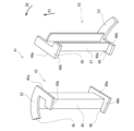
- core
- axial
- split
- Prior art date
- Legal status (The legal status is an assumption and is not a legal conclusion. Google has not performed a legal analysis and makes no representation as to the accuracy of the status listed.)
- Ceased
Links
Images






Classifications
-
- H—ELECTRICITY
- H02—GENERATION; CONVERSION OR DISTRIBUTION OF ELECTRIC POWER
- H02K—DYNAMO-ELECTRIC MACHINES
- H02K1/00—Details of the magnetic circuit
- H02K1/06—Details of the magnetic circuit characterised by the shape, form or construction
- H02K1/12—Stationary parts of the magnetic circuit
- H02K1/14—Stator cores with salient poles
- H02K1/146—Stator cores with salient poles consisting of a generally annular yoke with salient poles
- H02K1/148—Sectional cores
-
- H—ELECTRICITY
- H02—GENERATION; CONVERSION OR DISTRIBUTION OF ELECTRIC POWER
- H02K—DYNAMO-ELECTRIC MACHINES
- H02K3/00—Details of windings
- H02K3/46—Fastening of windings on the stator or rotor structure
- H02K3/52—Fastening salient pole windings or connections thereto
- H02K3/521—Fastening salient pole windings or connections thereto applicable to stators only
- H02K3/522—Fastening salient pole windings or connections thereto applicable to stators only for generally annular cores with salient poles
Definitions
- This disclosure relates to a stator structure used in a generator.
- Patent Document 1 discloses a generator in which a stator core is formed by arranging multiple split cores in the circumferential direction.
- a recess provided on one split core fits into a protrusion provided on the other split core.
- one aspect of the present disclosure aims to provide a generator stator structure that suppresses axial positional deviation of the split cores.
- One aspect of the present disclosure is a stator structure for a generator that includes a plurality of split cores arranged in a circumferential direction, an attachment that overlaps with the axial end faces of at least two adjacent split cores among the plurality of split cores, and a plurality of coils wound around the plurality of split cores and the attachment.
- FIG. 1 is a cross-sectional view of a generator including a stator structure according to a first embodiment.
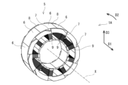
- FIG. 2 is a perspective view of a stator structure of the generator of FIG. 1 .
- 3 is a perspective view of a split core, an attachment, and a coil in the stator structure of FIG. 2.
- 4 is a cross-sectional view of a portion of the split core in FIG. 3 around which a coil is wound.
- FIG. 11 is a perspective view of a holder and a split core before being attached to the split core in a stator structure according to a second embodiment.
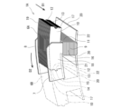
- 6 is a perspective view of the split core of FIG. 5 with a holder attached thereto and an attachment being attached thereto;
- FIG. 6 is a perspective view of the split core in FIG.
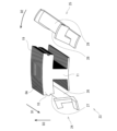
- FIG. 11 is a perspective view of a pair of halves of a stator structure according to a third embodiment. 9 is a perspective view of a holder and a split core formed by a pair of halves in FIG. 8 .
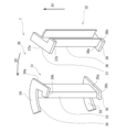
- FIG. 13 is a perspective view of a pair of halves of a stator structure according to a fourth embodiment. 11 is a perspective view of a holder and a split core formed by a pair of halves in FIG. 10 .
- the direction along the rotation axis X is defined as the axial direction D1
- the direction in which the multiple split cores 6 are arranged is defined as the circumferential direction D2
- the radial direction of a circle centered on the rotation axis X is defined as the radial direction D3.
- First Embodiment 1 is a cross-sectional view of a generator 2 including a stator structure 1A according to a first embodiment.
- the generator 2 is, for example, a generator provided inside a gas turbine engine.
- the generator 2 may be provided in other equipment.
- a generator 2 installed inside a gas turbine engine will be described.
- the gas turbine engine has a rotating shaft 3 extending in an axial direction D1 (FIG. 2).
- a rotor 4 is connected to the rotating shaft 3, and a stator structure 1A is arranged radially outside the rotor 4.
- the rotation axis X of the rotor 4 coincides with the rotation axis of the rotating shaft 3.
- the rotating shaft 3 is inserted into a hollow space on the rotation axis X of the rotor 4, and is connected so as to rotate together with the rotor 4.
- the rotating shaft 3 is connected to the inner peripheral surface of the rotor 4 by, for example, a spline connection.
- the generator 2 generates electricity as the rotating shaft 3 rotates, and the rotor 4 rotates.
- FIG. 2 is a perspective view of the stator structure 1A in the generator 2.
- the stator structure 1A has an annular stator core 5 formed by stacking magnetic bodies.
- the stator core 5 includes a plurality of split cores 6 arranged in the circumferential direction D2.
- the stator core 5 includes nine split cores 6, but the number of split cores is not particularly limited.
- the stator structure 1A includes attachments 7 and 8 arranged on one side and the other side in the axial direction D1. At least one attachment needs to be arranged on one side and the other side in the axial direction D1.
- the attachments 7 and 8 are end plates arranged on the axial end faces of the split core 6.
- the stator structure 1A also includes a coil 9 wound around the split core 6, the attachments 7, and the attachments 8.
- FIG. 3 is a perspective view of the first split core 6A, the attachment 7, the attachment 8, and the coil 9.
- the second split core 6B adjacent to the first split core 6A in the circumferential direction D2 is shown by a two-dot chain line.
- the first split core 6A and the second split core 6B of the stator core 5 have an arc portion 10 extending in the circumferential direction, and teeth 11 extending radially from the arc portion 10 and around which the coil 9 is wound.
- a groove 13 is provided on one end face 12 of the arc portion 10 in the circumferential direction D2.
- a protrusion 15 is provided on the other end face 14 of the arc portion 10 in the circumferential direction D2.
- the first split core 6A and the second split core 6B have an inner plate portion 20 having a plate-like shape that extends from the tooth portion 11 in both circumferential directions D2 at the radially inner end of the tooth portion 11. Because the first split core 6A and the second split core 6B have an inner plate portion 20 having a plate-like shape that extends from the tooth portion 11 in the circumferential direction D2 at the radially inner end, a larger current can be generated in the generator 2 in response to changes in the magnetic field caused by the rotation of the rotor 4, and the power generation efficiency of the generator 2 can be improved.
- Attachment 7 and attachment 8 have a base portion 16 superimposed on the axial end face of the tooth portion 11 of the first split core 6A, and a stopper portion 18 superimposed on the axial end face 17 of the arc portion 10 of the first split core 6A and the axial end face 17 of the arc portion 10 of the second split core 6B.
- the attachments 7 and 8 are formed in an L-shape with the stopper portion 18 extending from the base portion 16 in one direction in the circumferential direction D2.
- the L-shape does not have to be strictly L-shaped.
- the attachments 7 and 8 are attached to correspond to the multiple split cores 6.
- the multiple attachments 7 and 8 have the same shape, but may have multiple types of shapes.
- the attachments 7 and 8 are made of an insulator.
- the attachments 7 and 8 are made of, for example, heat-resistant polyimide. Note that, although the present embodiment describes a form in which the attachments 7 and 8 are made of an insulator, this is not limited to the above embodiment.
- the attachments 7 and 8 may also be made of a conductor with an insulating surface.
- Figure 4 is a cross-sectional view along a plane perpendicular to the tooth portion 11 in the portion of the first split core 6A of the stator structure 1A around which the coil 9 is wound.
- Figure 4 is a cross-sectional view at the radial midpoint of the tooth portion 11 of the first split core 6A around which the coil 9 is wound.
- An attachment 7 is attached to one end face in the axial direction D1 of the tooth portion 11 of the first split core 6A
- an attachment 8 is attached to the other end face in the axial direction D1 of the tooth portion 11 of the first split core 6A.
- the coil 9 is wound around the outer circumference of the attachment 7, the attachment 8 and the tooth portion 11.
- the ends of the bases 16 of the attachments 7 and 8 where the coil 9 is wound are curved. Therefore, the corner of one end of the attachments 7 and 8 in the axial direction D1 that contacts the coil 9 is configured to have a radius of curvature R1.
- the curved portions of the attachments 7 and 8 may have different radii of curvature between the attachments 7 and 8. Since the attachments 7 and 8 have a curved shape, the load applied to the coil 9 is reduced when the coil 9 is wound around the teeth 11 of the first split core 6A, the attachments 7 and 8.
- the ends of the attachments 7 and 8 where the coil 9 is wound are not limited to a curved shape, and may have a tapered shape with a surface that intersects obliquely with the end face in the axial direction D1, thereby removing the corner.
- the first split core 6A includes a plurality of magnetic plates 19 stacked in the axial direction D1.
- the first split core 6A is formed by stacking a plurality of magnetic plates 19 in the axial direction.
- the laminate of magnetic plates 19 is covered with a sheet-like insulator in the portion corresponding to the teeth 11 of the split core 6A.
- the sheet-like insulator is, for example, a sheet made of resin.
- an attachment 7 is attached to one side of the split core 6A in the axial direction D1
- an attachment 8 is attached to the other side of the split core 6A in the axial direction D1.
- the attachment 7 and the attachment 8 are bonded, for example, with an adhesive.
- the coil 9 is wound around the attachment 7, the attachment 8, and the teeth 11 of the split core 6A.
- the coil 9 positions the attachment 7 and the attachment 8 relative to the multiple magnetic plates 19 while fixing the multiple magnetic plates 19.
- the coil 9 can position the attachment 7 and the attachment 8 relative to the first split core 6A. Therefore, it is possible to suppress misalignment in the axial direction D1 of the first split core 6A and the second split core 6B, which are adjacent in the circumferential direction D2.
- Attachments 7 and 8 each include a stopper portion 18.
- the stopper portion 18 is overlapped with both the axial end face 17 of the arc portion 10 of the first split core 6A and the axial end face 17 of the arc portion 10 of the second split core 6B, and is positioned relative to the first split core 6A by the coil 9. Therefore, the stopper portion 18 can suppress misalignment of the first split core 6A and the second split core 6B in the axial direction D1.
- the other end face 12 of the arc portion 10 of the first split core 6A in the circumferential direction D2 abuts against one end face 14 of the arc portion 10 of the second split core 6B in the circumferential direction D2.
- the end face 14 of the arc portion 10 of the first split core 6A may include a protrusion
- the end face 12 of the arc portion 10 of the second split core 6B may include a groove 13.
- the inner plate portion 21 of the inner plate portion 20 of the split core 6A extending from the tooth portion 11 in one direction in the circumferential direction D2 abuts against the inner plate portion 22 of the inner plate portion 20 of the split core 6B extending from the tooth portion 11 in the other direction in the circumferential direction D2. Therefore, when the stator structure 1A is assembled, the adjacent first and second split cores 6A and 6B abut against each other in the circumferential direction D2.
- the stopper portions 18 of the attachments 7 and 8 are overlapped with both the axial end faces 17 of the arc portions 10 of the first split core 6A and the axial end faces 17 of the arc portions 10 of the second split core 6B, so that the stopper portions 18 can suppress misalignment of the first split core 6A and the second split core 6B in the axial direction D1.
- the ends of the parts of the bases 16 of the attachments 7 and 8 where the coil 9 is wound are curved or tapered, so the load on the coil 9 is reduced and breakage of the coil 9 can be prevented.
- the attachments 7 and 8 are end plates arranged on the axial end faces of the split core 6, so the configuration of the attachments 7 and 8 is simplified, and the manufacturing costs of the stator structure 1A can be kept low.
- multiple attachments 7 have the same shape, making manufacturing easier and reducing the manufacturing costs of the stator structure 1A.
- a groove 13 is provided on the circumferential end face 12 of the second split core 6B, and a protrusion 15 is provided on the circumferential end face 14 of the arc portion 10 of the first split core 6A.
- the attachments 7 and 8 are described as being formed in an L-shape, but this is not limited to the above embodiment.
- the number and shape of the attachments 7 and 8 are not particularly limited.
- the attachments 7 and 8 may be attached to all adjacent split cores, or to some of the split cores.
- the attachments may have any shape as long as they are placed on the axial end faces of at least two circumferentially adjacent split cores and can position the multiple split cores in the axial direction.
- the attachment 7 may be formed, for example, in a T-shape.
- the shapes of the multiple attachments 7 and 8 do not all have to be the same, and only certain attachments may have different shapes.
- a generator stator structure 1B according to a second embodiment will be described. Descriptions of parts common to the first embodiment will be omitted.
- a plurality of magnetic plates stacked in the axial direction are covered with an insulating holder attached to the magnetic plates from the outside in the circumferential direction.
- FIG. 5 is a perspective view of the first split core 6A and the holding body 23 before it is attached to the first split core 6A.
- the holding body 23 is a pair of halves, a first holding body 24 and a second holding body 25, which can be divided into two in the circumferential direction D2.
- the holding body 23 may be configured to be divisible into two or more parts.
- the holding body 23 is attached to the first split core 6A from both sides in the circumferential direction.
- the holder 23, the first holder 24 and the second holder 25, are both made of an insulator.
- the first holder 24 and the second holder 25 are made of, for example, polyimide. Note that in this embodiment, the first holder 24 and the second holder 25 are made of an insulator, but are not limited to the above embodiment.
- the first holder 24 and the second holder 25 may have their surfaces insulated.
- FIG. 6 shows an oblique view of the first split core 6A in a state in which the first retaining body 24 and the second retaining body 25 are attached to the first split core 6A and the attachment 7 and the attachment 8 are about to be attached.
- the first retaining body 24 has a tooth abutment portion 26 that abuts against the tooth portion 11 of the first split core 6A, an arc abutment portion 27 (FIG.
- the second retainer 25 has a tooth abutment portion 28 that abuts against the tooth portion 11 of the first split core 6A, an arc abutment portion 29 ( Figure 5) that abuts against the radially inner surface of the arc portion 10 of the first split core 6A, a plate-shaped inner protrusion portion 58 that protrudes outward in the axial direction D1 and circumferential direction D2 from the tooth abutment portion 28 radially inward from the tooth abutment portion 28, and an outer protrusion portion 59 that protrudes outward in the circumferential direction D2 from the tooth abutment portion 28 radially outward from the tooth abutment portion 28.
- Figure 7 shows an oblique view of the holding body 23 and the first split core 6A with the attachment 7 and the attachment 8 attached to the first split core 6A and the coil 9 wound around them.
- the second split core 6B which is adjacent to the first split core 6A in the circumferential direction, is shown by a two-dot chain line.
- the retaining body 23 is attached to both circumferential sides of the first split core 6A.
- An attachment 7 is attached to one axial end face of the retaining body 23, and an attachment 8 is attached to the other axial end face of the retaining body 23.
- the stopper portion 18 of the attachment 7 is provided on the retaining body 23 so as to overlap both the axial end face of the first split core 6A and the axial end face of the second split core 6B.
- the stopper portion of the attachment 8 is provided on the retaining body 23 so as to overlap both the axial end face of the first split core 6A and the axial end face of the second split core 6B.
- the attachment 7 is attached to the holding body 23 so that the base 16 of the attachment 7 abuts against the portion of the holding body 23 that holds the teeth 11 of the first split core 6A.
- the attachment 8 is attached to the holding body 23 so that the base of the attachment 8 abuts against the portion of the holding body 23 that holds the teeth 11 of the first split core 6A.
- the attachments 7 and 8 can be attached using, for example, an adhesive, but are not limited to this.
- the coil 9 is wound around the attachment 7, the attachment 8, and the teeth 11 of the split core 6A.
- the coil 9 positions the attachment 7 and the attachment 8 relative to the holder 23 while fixing the holder 23 attached to a plurality of magnetic plates 19.
- the coil 9 can position the holder 23, the attachment 7, and the attachment 8 relative to the first split core 6A. Therefore, it is possible to suppress misalignment in the axial direction D1 of the first split core 6A and the second split core 6B, which are adjacent in the circumferential direction D2.
- the retaining body 23 retains the multiple magnetic plates 19 stacked in the axial direction D1 in the circumferential and axial directions using the first retaining body 24 and the second retaining body 25.
- the multiple magnetic plates 19 are held in the radial direction D3 by the arc abutment portion 27 of the first retaining body 24 and the arc abutment portion 29 of the second retaining body 25. Therefore, the multiple magnetic plates 19 stacked in the axial direction D1 are stably held by the retaining body 23.
- the first holding body 24 is provided with an inner protrusion 56 and an outer protrusion 57
- the second holding body 25 is provided with an inner protrusion 58 and an outer protrusion 59
- the outer peripheral surfaces of the tooth abutment portions 26 and 28 serve as guides when winding the coil 9 around the first split core 6A, making it easy to wind the coil 9 around the first split core 6A.
- the attachment is attached to a holder composed of a pair of halves.
- Figure 8 is an oblique view of the retaining body 30 composed of a pair of halves.
- the first half 31 includes a first side plate portion 33 overlapping the tooth portion 11 of the first split core 6A ( Figure 9) from one side in the circumferential direction D2 and extending in the axial direction D1, a first end plate portion 34 connected to one end of the first side plate portion 33 in the axial direction D1 and overlapping the axial end face of the first split core 6A on one side in the axial direction D1, and a second end plate portion 35 connected to the other end of the first side plate portion 33 in the axial direction D1 and overlapping the axial end face of the first split core 6A on the other side in the axial direction D1.
- the second half 32 also includes a second side plate portion 36 that overlaps the tooth portion 11 of the first split core 6A (FIG. 9) from the other side in the circumferential direction D2 and extends in the axial direction D1, a first end plate portion 37 that is connected to one end of the second side plate portion 36 in the axial direction D1 and overlaps the axial end face of the first split core 6A on one side in the axial direction D1, and a second end plate portion 38 that is connected to the other end of the second side plate portion 36 in the axial direction D1 and overlaps the axial end face of the first split core 6A on the other side in the axial direction D1.
- the first half 31 has a first end plate portion 34 and a second end plate portion 35 that extend in the circumferential direction and abut against both the first split core 6A and the second split core 6B adjacent to the second split core 6A, and is provided with a stopper portion 54 and a stopper portion 55 that position the first split core 6A and the second split core 6B in the axial direction. Also, in the first half 31, the first end plate portion 34 and the second end plate portion 35 are provided with portions 34a, 35a that abut against the axial end face of the tooth portion 11 of the first split core 6A, and portions 34b, 35b that abut against the axial end face of the inner plate portion 22.
- the first end plate portion 37 and the second end plate portion 38 are provided with portions 37a, 38a that abut the axial end faces of the teeth portion 11 of the first split core 6A, and portions 37b, 38b that abut the axial end faces of the inner plate portion 22.
- the first end plate portion 37 and the second end plate portion 38 do not extend in the circumferential direction, and no stopper portion is provided that abuts both the first split core 6A and the second split core 6B adjacent to the first split core 6A.
- Figure 9 is a perspective view of the retaining body 30 and the first split core 6A.
- the second split core 6B which is adjacent to the first split core 6A in the circumferential direction, is shown by a two-dot chain line.
- the first end plate portion 34 of the first half 31 overlaps both the axial end face 39 on one side of the first split core 6A and the axial end face 40 on one side of the second split core 6B adjacent to the first split core 6A.
- the second end plate portion 35 ( Figure 8) of the first half 31 overlaps both the axial end face on the other side of the first split core 6A and the axial end face on the other side of the second split core 6B adjacent to the first split core 6A.
- the attachment 7 is attached to the holding body 30, which is composed of a pair of halves, and suppresses axial positional deviation of the adjacent first and second split cores 6A and 6B.
- the attachment 7 is part of the holding body 30.
- the part of the holding body 30 that suppresses positional deviation of the adjacent first and second split cores 6A and 6B is configured as the attachment 7.
- the holding body 30 holds the first split core 6A from both sides in the circumferential direction.
- the first half 31 and the second half 32 of the holder 30 are both made of an insulator.
- the first half 31 and the second half 32 are made of, for example, polyimide. Note that in this embodiment, the first half 31 and the second half 32 are made of an insulator, but are not limited to the above embodiment.
- the first half 31 and the second half 32 may be made of a conductor with an insulating treatment applied to the surface.
- the holding body 30 holds the first split core 6A, which is made up of multiple stacked magnetic plates 19, in the circumferential direction D2, so the first split core 6A can be held stably.
- the holder 30 to which the attachment 7 is attached can also serve as an insulator between the coil 9 and the first split core 6A, making it possible to simplify the configuration of a generator using a stator structure.
- the holder 30 includes a first half 31 and a second half 32, the first half 31 includes a first side plate portion 33, a first end plate portion 34, and a second end plate portion 35, and the second half 32 includes a first side plate portion 36, a first end plate portion 37, and a second end plate portion 38. Therefore, the first split core 6A can be held simply by attaching the first half 31 and the second half 32 to the first split core 6A. Therefore, the pair of halves 30 that sandwich the first split core 6A in the circumferential direction can be made to have a simple configuration.
- the first half 31 of the retaining body 30 includes the first end plate portion 34 and the second end plate portion 35, and the first end plate portion 34 and the second end plate portion 35 have the stopper portion 54 and the stopper portion 55 extending circumferentially in the portion corresponding to the arc portion 10 of the first split core 6A, so that the stopper portion 54 and the stopper portion 55 abut against both the first split core 6A and the second split core 6B adjacent to the first split core 6A, and position the first split core 6A and the second split core 6B adjacent to the first split core 6A in the axial direction D1. Therefore, it is possible to prevent the first split core 6A and the second split core 6B adjacent to the first split core 6A in the circumferential direction D2 from shifting in the axial direction D1.
- stator structure of a generator according to a fourth embodiment will be described. Note that a description of parts configured similarly to the first to third embodiments will be omitted.
- the attachment is attached to a holder configured of a pair of halves.
- Fig. 10 shows an oblique view of a retaining body 41 composed of a pair of halves.
- the first half 42 of the retaining body 41 includes a first side plate portion 44 overlapping the tooth portion 11 of the first split core 6A from one side in the circumferential direction D2 and extending in the axial direction D1, a first end plate portion 45 connected to one end of the first side plate portion 44 in the axial direction D1 and overlapping the axial end face of the first split core 6A on one side in the axial direction D1, and a second end plate portion 46 connected to the other end of the first side plate portion 44 in the axial direction D1 and overlapping the axial end face of the first split core 6A on the other side in the axial direction D1.
- the second half 43 of the retaining body 41 includes a second side plate portion 47 that overlaps the tooth portion 11 of the first split core 6A from the other side in the circumferential direction D2 and extends in the axial direction D1, a first end plate portion 48 that is connected to one end of the second side plate portion 47 in the axial direction D1 and overlaps the axial end face of the first split core 6A on one side in the axial direction D1, and a second end plate portion 49 that is connected to the other end of the second side plate portion 47 in the axial direction D1 and overlaps the axial end face of the first split core 6A on the other side in the axial direction D1.
- the first end plate portion 45 of the first half 42 overlaps both the axial end face 50 on one side of the first split core 6A and the axial end face 51 on one side of the second split core 6B adjacent to the first split core 6A (FIG. 11).
- the second end plate portion 46 of the first half 42 overlaps the tooth portion 11 of the first split core 6A but does not overlap the axial end face on the other side of the second split core 6B adjacent to the first split core 6A.
- the first end plate portion 45 extends circumferentially at a portion corresponding to the arc portion 10 of the first split core 6A and has a stopper portion 52 for axially positioning the first split core 6A and the second split core 6B, while the second end plate portion 46 does not have a stopper portion for axially positioning the first split core 6A and the second split core 6B.
- the first end plate portion 45 and the second end plate portion 46 are provided with portions 45a, 46a that abut the axial end faces of the teeth portion 11 of the first split core 6A, and portions 45b, 46b that abut the axial end faces of the inner plate portions.
- the first end plate portion 48 of the second half 43 overlaps with the tooth portion 11 of the first split core 6A, but does not overlap with the axial end face on one side of the third split core 6C adjacent to the first split core 6A.
- the second end plate portion 49 of the second half 43 overlaps with both the axial end face on the other side of the first split core 6A and the axial end face on the other side of the third split core 6C adjacent to the first split core 6A.
- the first end plate portion 48 of the second half 43 does not have a stopper portion that determines the axial positioning of the first split core 6A and the third split core 6C adjacent to the first split core 6A
- the second end plate portion 49 of the second half 43 extends in the circumferential direction at a portion corresponding to the arc portion 10 of the first split core 6A and has a stopper portion 53 that determines the axial positioning of the first split core 6A and the third split core 6C adjacent to the first split core 6A.
- first end plate portion 48 and the second end plate portion 49 are provided with portions 48a, 49a that abut the axial end surface of the tooth portion 11 of the first split core 6A, and portions 48b, 49b that abut the axial end surface of the inner plate portion.
- Figure 11 is a perspective view of the first split core 6A sandwiched between a pair of halves in the stator 1D of the generator according to the fourth embodiment.
- the second split core 6B adjacent to one side of the first split core 6A in the circumferential direction D2 and the third split core 6C adjacent to the other side of the first split core 6A in the circumferential direction D2 are shown by two-dot chain lines.
- the first end plate portion 45 of the first half 42 of the retaining body 41 determines the positioning of the first split core 6A and the second split core 6B adjacent to the first split core 6A in the axial direction D1, while the second end plate portion 46 of the first half does not determine the positioning of the first split core 6A and the second split core 6B in the axial direction D1.
- the first end plate portion 48 of the second half 43 does not determine the positioning of the first split core 6A and the third split core 6C in the axial direction D1
- the second end plate portion 49 of the second half 43 determines the positioning of the first split core 6A and the third split core 6C in the axial direction D1.
- the stator 1D of the generator includes an attachment 7 attached to a holding body 41.
- the attachment 7 is part of the holding body 41.
- the portion of the holding body 41 that suppresses misalignment of the adjacent first split core 6A, second split core 6B, and third split core 6C is configured as the attachment 7.
- the holding body 41 includes a first half 42 and a second half 43. The first half 42 and the second half 43 sandwich the first split core 6A in the circumferential direction, thereby attaching the holding body 41 to the first split core 6A.
- both the first half 42 and the second half 43 are formed from an insulator.
- the first half 42 and the second half 43 are formed from, for example, polyimide. Note that in this embodiment, a form in which the first half 42 and the second half 43 are formed from an insulator is described, but this is not limited to the above embodiment.
- the first half 42 and the second half 43 may also be formed from a conductor with an insulating treatment applied to the surface.
- first half 42 and the second half 43 can be made to have the same shape, so the shape of the halves can be made the same throughout the stator 1D. This reduces the manufacturing cost of the stator 1D and the manufacturing cost of the generator 2.
- the stator will be used in a high-temperature environment, and therefore a form has been described in which components such as the attachment, holder, and pair of halves are formed from heat-resistant polyimide; however, if the stator is not exposed to a high-temperature environment, the attachment, holder, and pair of halves do not require heat resistance.
- the attachment, holder, and pair of halves may be formed from a material that does not have heat resistance.
- the above embodiment has been described as an example of the technology disclosed in this application.
- the technology in this disclosure is not limited to this, and can be applied to embodiments in which modifications, substitutions, additions, omissions, etc. have been made as appropriate.
- some configurations or methods in one embodiment may be applied to other embodiments, and some configurations in an embodiment can be separated from other configurations in that embodiment and extracted as desired.
- the components described in the attached drawings and detailed description include not only components essential for solving the problem, but also components that are not essential for solving the problem, in order to illustrate the technology.
- the split core has an arc portion extending in the circumferential direction and a tooth portion extending radially from the arc portion and around which a coil is wound,
- the plurality of split cores include a first split core and a second split core adjacent to each other,
- the attachment comprises: a base portion overlapping an axial end surface of the tooth portion of the first split core; a stopper portion overlapping an axial end surface of the arc portion of the first split core and an axial end surface of the arc portion of the second split core.
- the first divided core and the second divided core have circumferential end surfaces that abut against each other in the circumferential direction, one of the circumferential end surface of the first divided core and the circumferential end surface of the second divided core has a groove extending in the axial direction and open in the axial direction, the other of the circumferential end surface of the first divided core and the circumferential end surface of the second divided core has a protrusion extending in the axial direction, 3.
- the pair of halves includes a first half and a second half,
- the first half is a first side plate portion overlapping the tooth portion of the divided core from one side in the circumferential direction and extending in the axial direction; a first end plate portion connected to one end of the first side plate portion in the axial direction and overlapping an axial end surface on one side of the split core in the axial direction; a second end plate portion connected to the other end of the first side plate portion in the axial direction and overlapping an axial end surface of the split core on the other side in the axial direction,
- the second half is a second side plate portion overlapping the tooth portion of the divided core from the other side in the circumferential direction and extending in the axial direction; a first end plate portion connected to one end of the second side plate portion in the axial direction and overlapping an axial end surface on one side of the split core in the axial direction; a second end plate portion connected to the other axial end of the second side plate portion and overlapping an axial end face of the split core
Landscapes
- Engineering & Computer Science (AREA)
- Power Engineering (AREA)
- Iron Core Of Rotating Electric Machines (AREA)
Abstract
Description
図1は、第1実施形態に係るステータ構造1Aを備えた発電機2の断面図である。本実施形態においては、発電機2は、例えば、ガスタービンエンジンの内部に設けられた発電機である。ただし、発電機2は、他の機器に設けられてもよい。
次に、第2実施形態に係る発電機のステータ構造1Bについて説明する。なお、第1実施形態と共通する部分については説明を省略する。第2実施形態は、軸方向に積層された複数の磁性板を複数の磁性板に対して周方向の外側から取り付ける絶縁性の保持体で被覆する。
次に、第3実施形態に係る発電機のステータ構造について説明する。なお、上記第1実施形態及び第2実施形態と共通する部分については説明を省略する。第3実施形態においては、アタッチメントは、一対の半体で構成される保持体に取り付けられている。
次に、第4実施形態に係る発電機のステータ構造について説明する。なお、第1実施形態ないし第3実施形態と同様に構成される部分については説明を省略する。第4実施形態においては、第3実施形態と同様に、アタッチメントは、一対の半体で構成される保持体に取り付けられている。
周方向に並べられた複数の分割コアと、
前記複数の分割コアのうち隣接する少なくとも2つの分割コアの軸方向端面と重なるアタッチメントと、
前記複数の分割コア及び前記アタッチメントに巻かれた複数のコイルと、を備えた、発電機のステータ構造。
前記分割コアは、前記周方向に延びた弧部と、前記弧部から径方向に延び且つコイルが巻かれる歯部と、を有し、
前記複数の分割コアは、互いに隣接する第1分割コア及び第2分割コアを含み、
前記アタッチメントは、
前記第1分割コアの前記歯部の軸方向端面に重ねられた基部と、
前記第1分割コアの前記弧部の軸方向端面及び前記第2分割コアの前記弧部の軸方向端面に重ねられたストッパ部と、を有する、項目1に記載の発電機のステータ構造。
前記第1分割コア及び前記第2分割コアは、互いに前記周方向に当接する周方向端面を有し、
前記第1分割コアの前記周方向端面及び前記第2分割コアの前記周方向端面の一方は、前記軸方向に延びて前記軸方向に開放された溝を有し、
前記第1分割コアの前記周方向端面及び前記第2分割コアの前記周方向端面の他方は、前記軸方向に延びた突起を有し、
前記突起は、前記溝に嵌合している、項目2に記載の発電機のステータ構造。
前記アタッチメントの前記基部のうちコイルが巻かれる部分の端部は、湾曲した形状又はテーパ形状を有する、項目2又は3に記載の発電機のステータ構造。
前記アタッチメントは、前記分割コアの前記軸方向端面に配置された端板である、項目1から4のいずれかに記載の発電機のステータ構造。
前記複数の分割コアのうち少なくとも1つの前記分割コアを前記周方向に挟む保持体を更に備え、
前記アタッチメントは、前記保持体に取り付けられている、項目1から5のいずれかに記載の発電機のステータ構造。
前記アタッチメントは、絶縁体である、項目1から6のいずれかに記載の発電機のステータ構造。
前記アタッチメントは、表面に絶縁処理が行われている、項目1から6のいずれかに記載の発電機のステータ構造。
前記一対の半体は、第1半体と、第2半体とを含み、
前記第1半体は、
前記分割コアの前記歯部に前記周方向の一方側から重なり且つ前記軸方向に延びた第1側板部と、
前記第1側板部の前記軸方向の一端に接続され、前記分割コアの前記軸方向の一方側の軸方向端面に重なる第1端板部と、
前記第1側板部の前記軸方向の他端に接続され、前記分割コアの前記軸方向の他方側の軸方向端面に重なる第2端板部と、を含み、
前記第2半体は、
前記分割コアの前記歯部に前記周方向の他方側から重なり且つ前記軸方向に延びた第2側板部と、
前記第2側板部の前記軸方向の一端に接続され、前記分割コアの前記軸方向の一方側の軸方向端面に重なる第1端板部と、
前記第2側板部の前記軸方向の他端に接続され、前記分割コアの前記軸方向の他方側の軸方向端面に重なる第2端板部と、を含む、項目6に記載の発電機のステータ構造。
前記第1半体の前記第1端板部は、対応する前記分割コアの一方側の軸方向端面と、対応する前記分割コアに隣接する前記分割コアの一方側の軸方向端面と、の両方と重なる、項目9に記載の発電機のステータ構造。
前記第1半体の前記第2端板部は、対応する前記分割コアの他方側の軸方向端面と、対応する前記分割コアに隣接する前記分割コアの他方側の軸方向端面と、の両方と重なる、項目10に記載の発電機のステータ構造。
前記第1半体及び前記第2半体は、互いに同じ形状を有する、項目9に記載の発電機のステータ構造。
2 発電機
5 ステータコア
6、6A、6B、6C 分割コア
7、8 アタッチメント
9 コイル
10 弧部
11 歯部
13 溝
15 突起
16 基部
18 ストッパ部
19 磁性板
30 保持体
31 第1半体
32 第2半体
33 第1側板部
34 第1端板部
35 第2端板部
36 第2側板部
37 第1端板部
38 第2端板部
41 保持体
42 第1半体
43 第2半体
44 第1側板部
45 第1端板部
46 第2端板部
47 第2側板部
48 第1端板部
49 第2端板部
52、53、54、55 ストッパ部
Claims (12)
- 周方向に並べられた複数の分割コアと、
前記複数の分割コアのうち隣接する少なくとも2つの分割コアの軸方向端面と重なるアタッチメントと、
前記複数の分割コア及び前記アタッチメントに巻かれた複数のコイルと、を備えた、発電機のステータ構造。 - 前記分割コアは、前記周方向に延びた弧部と、前記弧部から径方向に延び且つコイルが巻かれる歯部と、を有し、
前記複数の分割コアは、互いに隣接する第1分割コア及び第2分割コアを含み、
前記アタッチメントは、
前記第1分割コアの前記歯部の軸方向端面に重ねられた基部と、
前記第1分割コアの前記弧部の軸方向端面及び前記第2分割コアの前記弧部の軸方向端面に重ねられたストッパ部と、を有する、請求項1に記載の発電機のステータ構造。 - 前記第1分割コア及び前記第2分割コアは、互いに前記周方向に当接する周方向端面を有し、
前記第1分割コアの前記周方向端面及び前記第2分割コアの前記周方向端面の一方は、前記軸方向に延びて前記軸方向に開放された溝を有し、
前記第1分割コアの前記周方向端面及び前記第2分割コアの前記周方向端面の他方は、前記軸方向に延びた突起を有し、
前記突起は、前記溝に嵌合している、請求項2に記載の発電機のステータ構造。 - 前記アタッチメントの前記基部のうちコイルが巻かれる部分の端部は、湾曲した形状又はテーパ形状を有する、請求項2又は3に記載の発電機のステータ構造。
- 前記アタッチメントは、前記分割コアの前記軸方向端面に配置された端板である、請求項1又は2に記載の発電機のステータ構造。
- 前記複数の分割コアのうち少なくとも1つの前記分割コアを前記周方向に挟む保持体を更に備え、
前記アタッチメントは、前記保持体に取り付けられている、請求項1又は2に記載の発電機のステータ構造。 - 前記アタッチメントは、絶縁体である、請求項1又は2に記載の発電機のステータ構造。
- 前記アタッチメントは、表面に絶縁処理が行われている、請求項1又は2に記載の発電機のステータ構造。
- 前記保持体は、第1半体と、第2半体とを含み、
前記第1半体は、
前記分割コアの前記歯部に前記周方向の一方側から重なり且つ前記軸方向に延びた第1側板部と、
前記第1側板部の前記軸方向の一端に接続され、前記分割コアの前記軸方向の一方側の軸方向端面に重なる第1端板部と、
前記第1側板部の前記軸方向の他端に接続され、前記分割コアの前記軸方向の他方側の軸方向端面に重なる第2端板部と、を含み、
前記第2半体は、
前記分割コアの前記歯部に前記周方向の他方側から重なり且つ前記軸方向に延びた第2側板部と、
前記第2側板部の前記軸方向の一端に接続され、前記分割コアの前記軸方向の一方側の軸方向端面に重なる第1端板部と、
前記第2側板部の前記軸方向の他端に接続され、前記分割コアの前記軸方向の他方側の軸方向端面に重なる第2端板部と、を含む、請求項6に記載の発電機のステータ構造。 - 前記第1半体の前記第1端板部は、対応する前記分割コアの一方側の軸方向端面と、対応する前記分割コアに隣接する前記分割コアの一方側の軸方向端面と、の両方と重なる、請求項9に記載の発電機のステータ構造。
- 前記第1半体の前記第2端板部は、対応する前記分割コアの他方側の軸方向端面と、対応する前記分割コアに隣接する前記分割コアの他方側の軸方向端面と、の両方と重なる、請求項10に記載の発電機のステータ構造。
- 前記第1半体及び前記第2半体は、互いに同じ形状を有する、請求項9に記載の発電機のステータ構造。
Priority Applications (1)
| Application Number | Priority Date | Filing Date | Title |
|---|---|---|---|
| EP24831547.5A EP4734332A1 (en) | 2023-06-26 | 2024-05-29 | Stator structure of generator |
Applications Claiming Priority (2)
| Application Number | Priority Date | Filing Date | Title |
|---|---|---|---|
| JP2023-104432 | 2023-06-26 | ||
| JP2023104432A JP2025004623A (ja) | 2023-06-26 | 2023-06-26 | 発電機のステータ構造 |
Publications (1)
| Publication Number | Publication Date |
|---|---|
| WO2025004677A1 true WO2025004677A1 (ja) | 2025-01-02 |
Family
ID=93938207
Family Applications (1)
| Application Number | Title | Priority Date | Filing Date |
|---|---|---|---|
| PCT/JP2024/019665 Ceased WO2025004677A1 (ja) | 2023-06-26 | 2024-05-29 | 発電機のステータ構造 |
Country Status (3)
| Country | Link |
|---|---|
| EP (1) | EP4734332A1 (ja) |
| JP (1) | JP2025004623A (ja) |
| WO (1) | WO2025004677A1 (ja) |
Citations (9)
| Publication number | Priority date | Publication date | Assignee | Title |
|---|---|---|---|---|
| JP2001103690A (ja) * | 1999-09-28 | 2001-04-13 | Sanyo Denki Co Ltd | 回転電機用ステータ |
| US20060070228A1 (en) * | 2004-10-04 | 2006-04-06 | Stewart William P | Electric machines and methods related to assembling electric machines |
| WO2007029882A1 (ja) * | 2005-09-09 | 2007-03-15 | Toyota Jidosha Kabushiki Kaisha | ステータコア、モータ、ステータ製造方法 |
| JP2011176902A (ja) | 2010-02-23 | 2011-09-08 | Komatsu Ltd | 電機子およびその製造方法 |
| JP2011254689A (ja) * | 2010-06-04 | 2011-12-15 | Toyota Motor Corp | 絶縁部材、ステータの製造方法 |
| JP2015220875A (ja) * | 2014-05-19 | 2015-12-07 | 三菱電機株式会社 | 回転電機の固定子 |
| JP2018027001A (ja) * | 2016-07-28 | 2018-02-15 | 三星電子株式会社Samsung Electronics Co.,Ltd. | ステータ及びブラシレスモータ |
| JP2022000537A (ja) * | 2020-06-17 | 2022-01-04 | 日本製鉄株式会社 | 電磁鋼板、積層コア及び回転電機、ならびに電磁鋼板の製造方法 |
| WO2022249525A1 (ja) * | 2021-05-24 | 2022-12-01 | 三菱電機株式会社 | インシュレーター、ステーター、回転電機、ステーターの製造方法、および回転電機の製造方法 |
-
2023
- 2023-06-26 JP JP2023104432A patent/JP2025004623A/ja active Pending
-
2024
- 2024-05-29 WO PCT/JP2024/019665 patent/WO2025004677A1/ja not_active Ceased
- 2024-05-29 EP EP24831547.5A patent/EP4734332A1/en active Pending
Patent Citations (9)
| Publication number | Priority date | Publication date | Assignee | Title |
|---|---|---|---|---|
| JP2001103690A (ja) * | 1999-09-28 | 2001-04-13 | Sanyo Denki Co Ltd | 回転電機用ステータ |
| US20060070228A1 (en) * | 2004-10-04 | 2006-04-06 | Stewart William P | Electric machines and methods related to assembling electric machines |
| WO2007029882A1 (ja) * | 2005-09-09 | 2007-03-15 | Toyota Jidosha Kabushiki Kaisha | ステータコア、モータ、ステータ製造方法 |
| JP2011176902A (ja) | 2010-02-23 | 2011-09-08 | Komatsu Ltd | 電機子およびその製造方法 |
| JP2011254689A (ja) * | 2010-06-04 | 2011-12-15 | Toyota Motor Corp | 絶縁部材、ステータの製造方法 |
| JP2015220875A (ja) * | 2014-05-19 | 2015-12-07 | 三菱電機株式会社 | 回転電機の固定子 |
| JP2018027001A (ja) * | 2016-07-28 | 2018-02-15 | 三星電子株式会社Samsung Electronics Co.,Ltd. | ステータ及びブラシレスモータ |
| JP2022000537A (ja) * | 2020-06-17 | 2022-01-04 | 日本製鉄株式会社 | 電磁鋼板、積層コア及び回転電機、ならびに電磁鋼板の製造方法 |
| WO2022249525A1 (ja) * | 2021-05-24 | 2022-12-01 | 三菱電機株式会社 | インシュレーター、ステーター、回転電機、ステーターの製造方法、および回転電機の製造方法 |
Also Published As
| Publication number | Publication date |
|---|---|
| EP4734332A1 (en) | 2026-04-29 |
| JP2025004623A (ja) | 2025-01-15 |
Similar Documents
| Publication | Publication Date | Title |
|---|---|---|
| JP5885890B1 (ja) | 回転電機用固定子コア、回転電機及び回転電機の製造方法 | |
| WO2016185829A1 (ja) | 回転子、回転電機および回転子の製造方法 | |
| US11398754B2 (en) | Stator assembly and motor | |
| US10855122B2 (en) | Stator for rotating electrical machine having components for reinforcing laminations | |
| US11705764B2 (en) | Segmented stator for a generator, in particular for a wind turbine | |
| CN113039704A (zh) | 定子及使用该定子的电动机 | |
| WO2022249525A1 (ja) | インシュレーター、ステーター、回転電機、ステーターの製造方法、および回転電機の製造方法 | |
| JP2019221113A (ja) | ステータおよび回転電機 | |
| US12476499B2 (en) | Stator core of rotating electrical machine and rotating electrical machine | |
| JP7466495B2 (ja) | 電動機、送風装置及び電動機の製造方法 | |
| JP2025004623A (ja) | 発電機のステータ構造 | |
| JP4771010B1 (ja) | 回転電機および風力発電システム | |
| JP2021069186A (ja) | 回転電機 | |
| WO2015162765A1 (ja) | アキシャルギャップ型回転電機のステータコイル、ステータ、それを用いた回転電機及びその製造方法 | |
| EP3723241B1 (en) | Rotor core for rotating electric machine and method for manufacturing rotor core for rotating electric machine | |
| WO2024194959A1 (ja) | モータ | |
| US20260142521A1 (en) | Coil unit, armature, and rotating electrical machine | |
| JP2010239680A (ja) | 回転電機用電機子及びその製造方法 | |
| JP3671928B2 (ja) | 回転電機のアウターロータ構造 | |
| JP2021126025A (ja) | 回転電機の固定子、回転電機、および、回転電機の固定子の製造方法 | |
| KR20250148819A (ko) | 모터 | |
| JP7631367B2 (ja) | 埋め込み磁石型回転子および回転電機 | |
| CN220022423U (zh) | 定子、电机和车辆 | |
| WO2024018580A1 (ja) | 固定子及び回転電機 | |
| JP2015019452A (ja) | コイル及びコイル形成方法 |
Legal Events
| Date | Code | Title | Description |
|---|---|---|---|
| 121 | Ep: the epo has been informed by wipo that ep was designated in this application |
Ref document number: 24831547 Country of ref document: EP Kind code of ref document: A1 |
|
| ENP | Entry into the national phase |
Ref document number: 2024831547 Country of ref document: EP Effective date: 20260126 |
|
| WWE | Wipo information: entry into national phase |
Ref document number: 2024831547 Country of ref document: EP |
|
| NENP | Non-entry into the national phase |
Ref country code: DE |
|
| ENP | Entry into the national phase |
Ref document number: 2024831547 Country of ref document: EP Effective date: 20260126 |
|
| ENP | Entry into the national phase |
Ref document number: 2024831547 Country of ref document: EP Effective date: 20260126 |
|
| WWP | Wipo information: published in national office |
Ref document number: 2024831547 Country of ref document: EP |