WO2025004620A1 - 固体電解質材料の製造方法 - Google Patents
固体電解質材料の製造方法 Download PDFInfo
- Publication number
- WO2025004620A1 WO2025004620A1 PCT/JP2024/018752 JP2024018752W WO2025004620A1 WO 2025004620 A1 WO2025004620 A1 WO 2025004620A1 JP 2024018752 W JP2024018752 W JP 2024018752W WO 2025004620 A1 WO2025004620 A1 WO 2025004620A1
- Authority
- WO
- WIPO (PCT)
- Prior art keywords
- solid electrolyte
- electrolyte material
- producing
- solvent
- containing compound
- Prior art date
- Legal status (The legal status is an assumption and is not a legal conclusion. Google has not performed a legal analysis and makes no representation as to the accuracy of the status listed.)
- Ceased
Links
Images


Classifications
-
- H—ELECTRICITY
- H01—ELECTRIC ELEMENTS
- H01M—PROCESSES OR MEANS, e.g. BATTERIES, FOR THE DIRECT CONVERSION OF CHEMICAL ENERGY INTO ELECTRICAL ENERGY
- H01M10/00—Secondary cells; Manufacture thereof
- H01M10/05—Accumulators with non-aqueous electrolyte
- H01M10/056—Accumulators with non-aqueous electrolyte characterised by the materials used as electrolytes, e.g. mixed inorganic/organic electrolytes
- H01M10/0561—Accumulators with non-aqueous electrolyte characterised by the materials used as electrolytes, e.g. mixed inorganic/organic electrolytes the electrolyte being constituted of inorganic materials only
- H01M10/0562—Solid materials
-
- H—ELECTRICITY
- H01—ELECTRIC ELEMENTS
- H01M—PROCESSES OR MEANS, e.g. BATTERIES, FOR THE DIRECT CONVERSION OF CHEMICAL ENERGY INTO ELECTRICAL ENERGY
- H01M10/00—Secondary cells; Manufacture thereof
- H01M10/05—Accumulators with non-aqueous electrolyte
- H01M10/052—Li-accumulators
-
- H—ELECTRICITY
- H01—ELECTRIC ELEMENTS
- H01M—PROCESSES OR MEANS, e.g. BATTERIES, FOR THE DIRECT CONVERSION OF CHEMICAL ENERGY INTO ELECTRICAL ENERGY
- H01M2300/00—Electrolytes
- H01M2300/0017—Non-aqueous electrolytes
- H01M2300/0065—Solid electrolytes
- H01M2300/0068—Solid electrolytes inorganic
- H01M2300/008—Halides
-
- Y—GENERAL TAGGING OF NEW TECHNOLOGICAL DEVELOPMENTS; GENERAL TAGGING OF CROSS-SECTIONAL TECHNOLOGIES SPANNING OVER SEVERAL SECTIONS OF THE IPC; TECHNICAL SUBJECTS COVERED BY FORMER USPC CROSS-REFERENCE ART COLLECTIONS [XRACs] AND DIGESTS
- Y02—TECHNOLOGIES OR APPLICATIONS FOR MITIGATION OR ADAPTATION AGAINST CLIMATE CHANGE
- Y02E—REDUCTION OF GREENHOUSE GAS [GHG] EMISSIONS, RELATED TO ENERGY GENERATION, TRANSMISSION OR DISTRIBUTION
- Y02E60/00—Enabling technologies; Technologies with a potential or indirect contribution to GHG emissions mitigation
- Y02E60/10—Energy storage using batteries
Definitions
- This disclosure relates to a method for producing a solid electrolyte material.
- Patent Document 1 discloses a method for producing a sulfide solid electrolyte material.
- the present disclosure makes it possible to expand the process window in the manufacturing method of solid electrolyte materials containing Li, Ti, Al, and F.
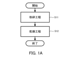
- FIG. 1A is a flowchart showing an example of a method for producing a solid electrolyte material in the first embodiment.
- FIG. 1B is a flowchart showing another example of the method for producing a solid electrolyte material in the first embodiment.
- FIG. 2 shows a cross-sectional view of a battery according to the second embodiment.
- FIG. 3 shows a cross-sectional view of a battery in the first modification.
- FIG. 4 shows a cross-sectional view of a battery in the second modification.
- FIG. 5 shows a schematic diagram of a pressure forming die used for evaluating the ionic conductivity of a solid electrolyte material.
- FIG. 6 is a graph showing a Cole-Cole plot obtained by impedance measurement of the solid electrolyte material of Example 1.
- FIG. 7 shows the change in ionic conductivity with the change in grinding time for the solid electrolyte materials of Examples 1 to 6 and Comparative Examples 1 to 3.
- FIG. 8 is a graph showing the
- FIG. 1A is a flowchart showing an example of a method for producing a solid electrolyte material in the first embodiment.
- the method for producing a solid electrolyte material in the first embodiment is a method for producing a solid electrolyte material containing Li, Ti, Al, and F.
- the method includes a grinding step S11 and a drying step S12.
- the grinding step S11 is performed before the drying step S12.
- a mixture M containing one or more compounds containing Li, Ti, Al, and F and a solvent is ground.
- the one or more compounds have a composition different from that of the solid electrolyte material to be produced.
- the drying step S12 the pulverized material obtained through the pulverization step S11 is dried. This removes the solvent contained in the pulverized material.
- the one or more compounds used in the grinding step S11 include Li2TiF6 .
- a method of heating a slurry obtained by grinding a raw material in a solvent is known. From the viewpoint of production efficiency, it is desirable to obtain a solid electrolyte material having high ionic conductivity in as short a grinding time as possible. In addition, the longer the grinding time, the more the raw material is altered and the ionic conductivity tends to decrease. This is thought to be caused by the fact that as the grinding time increases, the oxygen contained in the raw material increases, which causes a side reaction between the raw material and the solvent. From the viewpoint of production efficiency, it is desirable to suppress the progress of the decrease in the ionic conductivity of the solid electrolyte material.
- mixture M includes one or more compounds containing Li, Ti, Al, and F, and a solvent.
- Mixture M may also consist of one or more compounds containing Li, Ti, Al, and F, and a solvent.
- the one or more compounds include a Ti-containing compound.
- the Ti -containing compound include Li2TiF6 and ( NH4 ) 2TiF6 .
- the one or more compounds may include Li2TiF6 as a Ti-containing compound . According to the above configuration, the process window can be expanded.
- Li-containing compound examples include LiF, LiOH, and Li2CO3 .
- the one or more compounds may include LiF as the Li-containing compound. According to the above configuration, the process window can be expanded.
- the one or more compounds may include an Al-containing compound.
- Al-containing compound examples include AlF 3 , (NH 4 ) 3 AlF 6 , and Li 3 AlF 6 .
- the one or more compounds may include AlF 3 as the Al-containing compound. According to the above configuration, the process window can be expanded.
- the one or more compounds may include three or more compounds including a Ti-containing compound, a Li-containing compound, and an Al-containing compound.
- the one or more compounds may be a triple compound consisting of a Ti-containing compound, a Li-containing compound, and an Al-containing compound.
- a mixture M containing Li 2 TiF 6 , LiF, and AlF 3 and a solvent may be pulverized.
- the grinding process in the grinding step S11 is a wet grinding process.
- the material is mixed with a solvent and then ground by mainly shearing and frictional forces.
- the surfaces of the material particles are scraped off to generate small particles.
- the solvent used in the grinding step S11 may be an organic solvent or an inorganic solvent such as water, but it is preferable that it is an organic solvent.
- the organic solvent may contain a compound having an ester group.
- one or more compounds exhibit very good dispersibility in the organic solvent. Therefore, according to the above configuration, the ionic conductivity of the solid electrolyte material can be improved.
- the organic solvent may contain at least one selected from the group consisting of ⁇ -butyrolactone, propylene carbonate, butyl acetate, and tetralin.
- the one or more compounds exhibit very good dispersibility in the organic solvent. Therefore, according to the above configuration, the ionic conductivity of the solid electrolyte material can be improved.
- the grinding method in the grinding step S11 is not particularly limited.
- a ball mill, a pot mill, a bead mill, a V-type mixer, a double cone type mixer, an automatic mortar, or the like may be used.
- the raw material powder and the solvent may be placed in a mixing device such as a planetary ball mill and mixed while being finely pulverized.
- the grinding time in the grinding step S11 can be appropriately set depending on the grinding method. For example, when a planetary ball mill is used, the ionic conductivity of the solid electrolyte material can reach 3 ⁇ 10 ⁇ S/m with a grinding time of 10 hours. Even if the grinding time exceeds 45 hours, the ionic conductivity of the solid electrolyte can be maintained at 3 ⁇ 10 ⁇ S/m or more.
- the pulverization step S11 is performed so that the BET specific surface area of the solid electrolyte material is 25 m 2 /g or more, and thus the process window is easily expanded. That is, the pulverization step S11 may be performed so that the BET specific surface area of the solid electrolyte material is 25 m 2 /g or more.
- the upper limit of the BET specific surface area of the solid electrolyte material obtained by the pulverization step S11 is not particularly limited.
- the upper limit of the BET specific surface area of the solid electrolyte material may be, for example, 100 m 2 /g, 70 m 2 /g, 50 m 2 /g, 45 m 2 /g, 40 m 2 /g, or even 35 m 2 /g.
- the BET specific surface area of a solid electrolyte material can be determined, for example, by converting the adsorption isotherm data obtained by a gas adsorption method using nitrogen gas into the BET (Brunauer-Emmett-Teller) method.
- the solvent may be removed from the pulverized material by heating the pulverized material under an inert gas atmosphere.
- the heating temperature is, for example, 50°C or higher and 300°C or lower.
- the solvent in the drying step S12, may be removed from the pulverized material by reduced pressure drying.
- Reduced pressure drying is a method of removing the solvent from the pulverized material under a pressure atmosphere lower than atmospheric pressure.
- the pressure atmosphere lower than atmospheric pressure is, for example, -0.01 MPa or less in gauge pressure.
- the solvent in the drying step S12, may be removed from the pulverized material by vacuum drying.
- Vacuum drying is a method of removing the solvent from the pulverized material at or below the vapor pressure at a temperature 20°C lower than the boiling point of the solvent.
- the heating temperature of the pulverized material in reduced pressure drying or vacuum drying is, for example, 50°C or higher and 300°C or lower.
- FIG. 1B is a flowchart showing another example of a method for producing a solid electrolyte material in the first embodiment.
- the method for producing a solid electrolyte material in the first embodiment may further include a heating step S10.
- the heating step S10 is performed before the grinding step S11.
- the mixture M1 containing two or more compounds including TiF4 and LiF and a solvent is heated, whereby Li2TiF6 is synthesized.
- the mixture M2 containing the composition obtained through the heating step S10 and the Al-containing compound is pulverized.
- the composition obtained through the heating step S10 contains Li2TiF6 .
- the Al-containing compound may contain AlF3 .
- the example shown in FIG. 1B differs from the example shown in FIG. 1A in that Li 2 TiF 6 is pre-synthesized by a heating step S10.
- the drying step S12 the pulverized material obtained through the pulverization step S11 is dried. This removes the solvent contained in the pulverized material.
- the above configuration also makes it possible to expand the process window, for example the range of optimal grinding time.
- the mixture M1 includes two or more compounds including TiF4 and LiF and a solvent.
- the mixture M1 may be composed of two or more compounds including TiF4 and LiF and a solvent.
- mixture M2 includes a composition obtained through heating step S10 and an Al-containing compound.
- Mixture M2 may be composed of a composition obtained through heating step S10 and an Al-containing compound.
- the grinding step S11 and the drying step S12 in the example shown in FIG. 1B correspond to the grinding step S11 and the drying step S12 in the example shown in FIG. 1A, respectively. Therefore, a detailed description is omitted.
- a mixture M3 including three or more compounds including TiF 4 , LiF, and an Al-containing compound and a solvent may be heated. This may result in Li 2 TiF 6 being synthesized.
- the composition obtained through the heating step S10 is ground.
- the composition obtained through the heating step S10 includes Li 2 TiF 6 and an Al-containing compound. That is, in the example shown in FIG. 1B, the Al-containing compound may be added in the heating step S10.
- the above configuration also makes it possible to expand the process window, for example the range of optimal grinding time.
- the mixture M3 includes three or more compounds including TiF4 , LiF, and an Al-containing compound, and a solvent.
- the mixture M3 may consist of three or more compounds including TiF4 , LiF, and an Al-containing compound, and a solvent.
- the first solid electrolyte material contains Li, Ti, Al, and F.
- the first solid electrolyte material can have high ionic conductivity.
- the first solid electrolyte material contains F and can have high oxidation resistance. This is because F has a high redox potential. On the other hand, F has a high electronegativity, so it is relatively strongly bonded to Li. As a result, the lithium ion conductivity of a solid electrolyte material containing Li and F usually tends to be low.
- LiBF 4 disclosed in Patent Document 2 has a low ion conductivity of 6.67 ⁇ 10 ⁇ 9 S/cm.
- the first solid electrolyte material contains Ti and Al in addition to Li and F, and can have a high ion conductivity of, for example, 7 ⁇ 10 ⁇ 9 S/cm or more.
- the first solid electrolyte material can be used, for example, to obtain a battery with excellent charge/discharge characteristics.
- An example of such a battery is an all-solid-state battery.
- the all-solid-state battery may be a primary battery or a secondary battery.
- the first solid electrolyte material desirably does not contain sulfur.
- a solid electrolyte material that does not contain sulfur is safe because it does not generate hydrogen sulfide even when exposed to the atmosphere.
- the sulfide solid electrolyte disclosed in Patent Document 1 can generate hydrogen sulfide when exposed to the atmosphere.
- the first solid electrolyte material may further contain anions other than F.
- anions other than F examples include Cl, Br, I, O, and Se.
- the ratio R of the amount of substance of F to the sum of the amounts of substances of the anions of the first solid electrolyte material may be 0.50 or more.
- the ratio R may be 0.50 or more and 1.0 or less.
- the anion constituting the first solid electrolyte material may be F only.
- the ratio R may be 1.0.
- the first solid electrolyte material may consist essentially of Li, Ti, Al, and F.
- the first solid electrolyte material consists essentially of Li, Ti, Al, and F
- the ratio of the total amount of substance of Li, Ti, Al, and F to the total amount of substance of all elements constituting the first solid electrolyte material i.e., the molar fraction
- the ratio i.e., the molar fraction
- the first solid electrolyte material may consist only of Li, Ti, Al, and F.
- the first solid electrolyte material may contain elements that are inevitably mixed in. Examples of such elements are hydrogen, oxygen, or nitrogen. Such elements may be present in the raw material powder of the first solid electrolyte material or in the atmosphere in which the first solid electrolyte material is manufactured or stored.
- the first solid electrolyte material may be represented by the following formula (1):
- a solid electrolyte material having such a composition has high ionic conductivity.
- 0.1 ⁇ x ⁇ 0.7 may be satisfied in formula (1).
- the upper and lower limits of the range of x in formula (1) can be defined by any combination selected from the numerical values 0.1, 0.3, 0.4, 0.5, 0.6, 0.67, 0.7, 0.8, and 0.9.
- the upper and lower limits of the range of a in formula (1) can be defined by any combination selected from the numerical values of 0.8, 0.9, 0.94, 1.0, 1.06, 1.1, and 1.2.
- the first solid electrolyte material may be represented by the following formula (2).
- ⁇ , ⁇ , ⁇ , and ⁇ are each independently a value greater than 0.
- the first solid electrolyte material may be represented by the following formula (3).
- M is at least one selected from the group consisting of Zr, Ni, Fe, and Cr
- m is the valence of M2, and 0.1 ⁇ x ⁇ 0.9, 0 ⁇ y ⁇ 0.1, 0 ⁇ z ⁇ 0.1, and 0.8 ⁇ b ⁇ 1.2 are satisfied.
- m is the total value of the product of the composition ratio of each element and the valence of the element.
- M contains element Me1 and element Me2
- element Me1 has a composition ratio of a1 and a valence of m1
- element Me2 has a composition ratio of a2 and a valence of m2
- m is expressed as m1 x a1 + m2 x a2.
- the ratio of the amount of Li to the sum of the amounts of Ti and Al may be 1.12 or more and 5.07 or less.
- the first solid electrolyte material may be Li2.7Ti0.3Al0.7F6 .
- the first solid electrolyte material may be crystalline or amorphous.
- the first solid electrolyte material may include a crystalline phase represented by formula (1).
- the shape of the first solid electrolyte material is not limited. Examples of the shape are needle-like, spherical, or elliptical.
- the first solid electrolyte material may be in the form of particles.
- the first solid electrolyte material may have the shape of a pellet or a plate.
- the first solid electrolyte material is Li 2.7 Ti 0.3 Al 0.7 F 6
- one or more compounds containing Li, Ti, Al, and F weighed to have the desired composition and having a different composition from the first solid electrolyte material are mixed with a solvent in a mixing device while being pulverized.
- LiF, Li2TiF6 , and AlF3 are prepared in a molar ratio of about 2.1: 0.3 :0.7.
- the raw material powder may be prepared in a pre-adjusted molar ratio to offset composition changes that may occur in the synthesis process.
- the raw material powder and the solvent may be put into a mixing device such as a planetary ball mill and mixed while being pulverized. That is, a treatment using a wet ball mill may be performed.
- the raw material powder may be mixed before being put into the mixing device.
- the balls After mixing, the balls are separated to obtain a slurry in which the particles are dispersed.
- the solvent is removed by drying the slurry at a temperature according to the boiling point of the solvent used. This results in a first solid electrolyte material having a composition represented by Li2.7Ti0.3Al0.7F6 .
- the first solid electrolyte material may be pulverized using a mortar or the like .
- the first solid electrolyte material may be sintered in a vacuum or in an inert atmosphere.
- the sintering is carried out, for example, at a temperature of 100°C or higher and 300°C or lower for 1 hour or longer.
- the sintering may be carried out in a sealed container such as a quartz tube.
- the solvent used in the wet ball mill may contain at least one selected from the group consisting of ⁇ -butyrolactone (GBL), propylene carbonate, butyl acetate, and tetralin. From the viewpoint of the dielectric constant of the solvent, N-methyl-2-pyrrolidone (NMP) may be used as the solvent.
- GBL ⁇ -butyrolactone
- NMP N-methyl-2-pyrrolidone
- the battery in the second embodiment includes a positive electrode, a separator portion, and a negative electrode.
- the separator portion is located between the positive electrode and the negative electrode.
- the separator section may be a solid electrolyte layer, or a separator impregnated with an electrolyte solution.
- FIG. 2 shows a cross-sectional view of the battery 100 in the second embodiment.
- the battery 100 includes a positive electrode 21, a solid electrolyte layer 22, and a negative electrode 23.
- the solid electrolyte layer 22 is located between the positive electrode 21 and the negative electrode 23.
- the separator portion is the solid electrolyte layer 22.
- the positive electrode 21 contains a positive electrode active material 24 and a solid electrolyte 10.
- the solid electrolyte layer 22 contains an electrolyte material.
- the negative electrode 23 contains a negative electrode active material 25 and a solid electrolyte 10.
- the solid electrolyte 10 may contain a first solid electrolyte material.
- the solid electrolyte 10 may be particles containing the first solid electrolyte material as a main component. Particles containing the first solid electrolyte material as a main component refer to particles in which the component contained most abundantly in terms of molar ratio is the first solid electrolyte material.
- the solid electrolyte 10 may be particles made of the first solid electrolyte material.
- the positive electrode 21 contains a material capable of absorbing and releasing metal ions (e.g., lithium ions).
- the material is, for example, a positive electrode active material 24.
- Examples of the positive electrode active material 24 include a lithium-containing transition metal oxide, a transition metal fluoride, a polyanion, a fluorinated polyanion material, a transition metal sulfide, a transition metal oxyfluoride, a transition metal oxysulfide, or a transition metal oxynitride.
- Examples of the lithium-containing transition metal oxide include Li(Ni,Co,Mn) O2 , Li(Ni,Co,Al) O2 , or LiCoO2 .
- (A, B, C) means "at least one selected from the group consisting of A, B, and C.”
- the shape of the positive electrode active material 24 is not limited to a specific shape.
- the positive electrode active material 24 may be particulate.
- the positive electrode active material 24 may have a median diameter of 0.1 ⁇ m or more and 100 ⁇ m or less. When the positive electrode active material 24 has a median diameter of 0.1 ⁇ m or more, the positive electrode active material 24 and the solid electrolyte 10 can be well dispersed in the positive electrode 21. This improves the charge and discharge characteristics of the battery 100. When the positive electrode active material 24 has a median diameter of 100 ⁇ m or less, the lithium diffusion rate in the positive electrode active material 24 improves. This allows the battery 100 to operate at high power.
- the positive electrode active material 24 may have a larger median diameter than the solid electrolyte 10. This allows the positive electrode active material 24 and the solid electrolyte 10 to be well dispersed in the positive electrode 21.
- the ratio of the volume of the positive electrode active material 24 to the sum of the volume of the positive electrode active material 24 and the volume of the solid electrolyte 10 may be 0.30 or more and 0.95 or less.
- a coating layer may be formed on at least a portion of the surface of the positive electrode active material 24.
- the coating layer may be formed on the surface of the positive electrode active material 24, for example, before mixing with the conductive assistant and the binder.
- coating materials included in the coating layer include a sulfide solid electrolyte, an oxide solid electrolyte, or a halide solid electrolyte.
- the coating material may contain a first solid electrolyte material in order to suppress oxidative decomposition of the sulfide solid electrolyte.
- the coating material may contain an oxide solid electrolyte in order to suppress oxidative decomposition of the first solid electrolyte material.
- Lithium niobate which has excellent stability at high potentials, may be used as the oxide solid electrolyte. By suppressing oxidative decomposition, the overvoltage rise of the battery 100 can be suppressed.
- the positive electrode 21 may have a thickness of 10 ⁇ m or more and 500 ⁇ m or less.
- the negative electrode 23 contains a material capable of absorbing and releasing metal ions (e.g., lithium ions).
- the material is, for example, the negative electrode active material 25.
- Examples of the negative electrode active material 25 are metal materials, carbon materials, oxides, nitrides, tin compounds, or silicon compounds.
- the metal material may be a single metal or an alloy.
- Examples of the metal material are lithium metal or lithium alloys.
- Examples of the carbon material are natural graphite, coke, partially graphitized carbon, carbon fiber, spherical carbon, artificial graphite, or amorphous carbon. From the viewpoint of capacity density, suitable examples of the negative electrode active material are silicon (i.e., Si), tin (i.e., Sn), silicon compounds, or tin compounds.
- the negative electrode active material 25 may be selected in consideration of the reduction resistance of the solid electrolyte material contained in the negative electrode 23.
- the negative electrode active material 25 may be a material capable of absorbing and releasing lithium ions at 0.27 V or more relative to lithium.
- examples of such negative electrode active materials are titanium oxide, indium metal, or lithium alloy.
- examples of titanium oxide are Li 4 Ti 5 O 12 , LiTi 2 O 4 , or TiO 2.
- the shape of the negative electrode active material 25 is not limited to a specific shape.
- the negative electrode active material 25 may be particles.
- the negative electrode active material 25 may have a median diameter of 0.1 ⁇ m or more and 100 ⁇ m or less.
- the negative electrode active material 25 and the solid electrolyte 10 can be well dispersed in the negative electrode 23. This improves the charge and discharge characteristics of the battery 100.
- the negative electrode active material 25 has a median diameter of 100 ⁇ m or less, the lithium diffusion rate in the negative electrode active material 25 improves. This allows the battery 100 to operate at high power.
- the negative electrode active material 25 may have a median diameter larger than that of the solid electrolyte 10. This allows the negative electrode active material 25 and the solid electrolyte 10 to be well dispersed in the negative electrode 23.
- the ratio of the volume of the negative electrode active material 25 to the sum of the volume of the negative electrode active material 25 and the volume of the solid electrolyte 10 may be 0.30 or more and 0.95 or less.
- the negative electrode 23 may have a thickness of 10 ⁇ m or more and 500 ⁇ m or less.
- the solid electrolyte layer 22 contains an electrolyte material.
- the electrolyte material is, for example, a solid electrolyte material.
- the solid electrolyte material may contain a first solid electrolyte material.
- the solid electrolyte layer 22 may contain 50% or more by mass of the first solid electrolyte material.
- the solid electrolyte layer 22 may contain 70% or more by mass of the first solid electrolyte material.
- the solid electrolyte layer 22 may contain 90% or more by mass of the first solid electrolyte material.
- the solid electrolyte layer 22 may consist of only the first solid electrolyte material.
- At least one selected from the group consisting of the positive electrode 21, the solid electrolyte layer 22, and the negative electrode 23 may contain a second solid electrolyte material having a different composition from the first solid electrolyte material for the purpose of increasing ionic conductivity, chemical stability, and electrochemical stability.
- the solid electrolyte layer 22 may contain a second solid electrolyte material.
- the first solid electrolyte material and the second solid electrolyte material may be uniformly dispersed.
- the solid electrolyte layer 22 may consist only of the second solid electrolyte material.
- the second solid electrolyte material may be a halide solid electrolyte.
- halide solid electrolytes are Li2MgX4 , Li2FeX4 , Li(Al,Ga,In) X4 , Li3 (Al,Ga,In) X6 , or LiI, where X is at least one selected from the group consisting of F, Cl, Br, and I.
- halide solid electrolyte is a compound represented by Li a Me b Y c Z 6.
- Me is at least one selected from the group consisting of metal elements other than Li and Y and metalloid elements.
- Z is at least one selected from the group consisting of F, Cl, Br, and I.
- m represents the valence of Me.
- Metalloid elements are B, Si, Ge, As, Sb, and Te.
- Metal elements are all elements included in Groups 1 to 12 of the periodic table (excluding hydrogen), and all elements included in Groups 13 to 16 of the periodic table (excluding B, Si, Ge, As, Sb, Te, C, N, P, O, S, and Se).
- Me may be at least one selected from the group consisting of Mg, Ca, Sr, Ba, Zn, Sc, Al, Ga, Bi, Zr, Hf, Ti, Sn, Ta, and Nb.
- the halide solid electrolyte may be Li3YCl6 or Li3YBr6 .
- the second solid electrolyte material may be a sulfide solid electrolyte.
- Examples of sulfide solid electrolytes are Li2S - P2S5 , Li2S - SiS2 , Li2S - B2S3 , Li2S - GeS2 , Li3.25Ge0.25P0.75S4 , or Li10GeP2S12 .
- the negative electrode 23 may contain a sulfide solid electrolyte to suppress reductive decomposition of the solid electrolyte material.
- the electrochemically stable sulfide solid electrolyte covers the negative electrode active material, thereby suppressing contact between the first solid electrolyte material and the negative electrode active material. As a result, the internal resistance of the battery 100 can be reduced.
- the second solid electrolyte material may be an oxide solid electrolyte.
- oxide solid electrolytes include: (i) NASICON-type solid electrolytes such as LiTi2 ( PO4 ) 3 or elemental substitutions thereof; (ii) Perovskite-type solid electrolytes such as (LaLi) TiO3 ; (iii ) LISICON-type solid electrolytes such as Li14ZnGe4O16, Li4SiO4 , LiGeO4 or elemental substitutions thereof ; (iv) a garnet-type solid electrolyte such as Li7La3Zr2O12 or its elemental substitutions, or (v) Li3PO4 or its N - substituted derivatives ; It is.
- the second solid electrolyte material may be an organic polymer solid electrolyte.
- organic polymer solid electrolytes examples include polymer compounds and lithium salt compounds.
- the polymer compound may have an ethylene oxide structure.
- a polymer compound having an ethylene oxide structure can contain a large amount of lithium salt, and therefore can further increase the ionic conductivity.
- lithium salts are LiPF6 , LiBF4 , LiSbF6, LiAsF6 , LiSO3CF3 , LiN ( SO2CF3 ) 2 , LiN (SO2C2F5)2, LiN(SO2CF3)(SO2C4F9), or LiC(SO2CF3)3 .
- One lithium salt selected from these may be used alone. Alternatively, a mixture of two or more lithium salts selected from these may be used.
- At least one selected from the group consisting of the positive electrode 21, the solid electrolyte layer 22, and the negative electrode 23 may contain a nonaqueous electrolyte solution, a gel electrolyte, or an ionic liquid to facilitate the transfer of lithium ions and improve the output characteristics of the battery 100.
- the non-aqueous electrolyte contains a non-aqueous solvent and a lithium salt dissolved in the non-aqueous solvent.
- non-aqueous solvents examples include cyclic carbonate solvents, chain carbonate solvents, cyclic ether solvents, chain ether solvents, cyclic ester solvents, chain ester solvents, or fluorine solvents.
- cyclic carbonate solvents are ethylene carbonate, propylene carbonate, or butylene carbonate.
- chain carbonate solvents are dimethyl carbonate, ethyl methyl carbonate, or diethyl carbonate.
- Examples of cyclic ether solvents are tetrahydrofuran, 1,4-dioxane, or 1,3-dioxolane.
- chain ether solvents are 1,2-dimethoxyethane or 1,2-diethoxyethane.
- An example of a cyclic ester solvent is ⁇ -butyrolactone.
- An example of a chain ester solvent is methyl acetate.
- fluorine solvents are fluoroethylene carbonate, methyl fluoropropionate, fluorobenzene, fluoroethyl methyl carbonate, or fluorodimethylene carbonate.
- One non-aqueous solvent selected from these may be used alone. Alternatively, a combination of two or more non-aqueous solvents selected from these may be used.
- lithium salt examples include LiPF6 , LiBF4 , LiSbF6, LiAsF6 , LiSO3CF3 , LiN ( SO2CF3 ) 2 , LiN ( SO2C2F5 ) 2 , LiN( SO2CF3 )(SO2C4F9), or LiC (SO2CF3)3 .
- One lithium salt selected from these may be used alone. Alternatively, a mixture of two or more lithium salts selected from these may be used.
- the concentration of the lithium salt is, for example , in the range of 0.5 mol/L or more and 2 mol/L or less.
- a polymer material impregnated with a non-aqueous electrolyte may be used.
- polymer materials are polyethylene oxide, polyacrylonitrile, polyvinylidene fluoride, polymethyl methacrylate, or a polymer having an ethylene oxide bond.
- cations contained in ionic liquids are: (i) Aliphatic chain quaternary salts such as tetraalkylammonium or tetraalkylphosphonium; (ii) aliphatic cyclic ammoniums such as pyrrolidiniums, morpholiniums, imidazoliniums, tetrahydropyrimidiniums, piperaziniums, or piperidiniums, or (iii) nitrogen-containing heterocyclic aromatic cations such as pyridiniums or imidazoliums, It is.
- Aliphatic chain quaternary salts such as tetraalkylammonium or tetraalkylphosphonium
- aliphatic cyclic ammoniums such as pyrrolidiniums, morpholiniums, imidazoliniums, tetrahydropyrimidiniums, piperaziniums, or piperidiniums
- nitrogen-containing heterocyclic aromatic cations
- Examples of anions contained in the ionic liquid are PF6- , BF4- , SbF6- , AsF6- , SO3CF3- , N ( SO2CF3 ) 2- , N ( SO2C2F5 ) 2- , N( SO2CF3 ) ( SO2C4F9 ) - , or C ( SO2CF3 ) 3- .
- the ionic liquid may contain a lithium salt.
- At least one selected from the group consisting of the positive electrode 21, the solid electrolyte layer 22, and the negative electrode 23 may contain a binder to improve adhesion between particles.
- binders are polyvinylidene fluoride, polytetrafluoroethylene, polyethylene, polypropylene, aramid resins, polyamides, polyimides, polyamideimides, polyacrylonitrile, polyacrylic acid, polymethyl ester of acrylic acid, polyethyl ester of acrylic acid, polyhexyl ester of acrylic acid, polymethacrylic acid, polymethyl ester of methacrylic acid, polyethyl ester of methacrylic acid, polyhexyl ester of methacrylic acid, polyvinyl acetate, polyvinylpyrrolidone, polyether, polyethersulfone, hexafluoropolypropylene, styrene butadiene rubber, or carboxymethyl cellulose.
- Copolymers may also be used as binders.
- binders are copolymers of two or more materials selected from the group consisting of tetrafluoroethylene, hexafluoroethylene, hexafluoropropylene, perfluoroalkyl vinyl ether, vinylidene fluoride, chlorotrifluoroethylene, ethylene, propylene, pentafluoropropylene, fluoromethyl vinyl ether, acrylic acid, and hexadiene.
- a mixture of two or more materials selected from these may be used as a binder.
- At least one selected from the positive electrode 21 and the negative electrode 23 may contain a conductive additive to improve electronic conductivity.
- Examples of the conductive additive include: (i) graphites, such as natural or synthetic graphite; (ii) Carbon blacks such as acetylene black or ketjen black; (iii) conductive fibers, such as carbon or metal fibers; (iv) fluorocarbons, (v) metal powders such as aluminum; (vi) conductive whiskers such as zinc oxide or potassium titanate; (vii) a conductive metal oxide, such as titanium oxide; or (viii) a conductive polymer, such as polyaniline, polypyrrole, or polythiophene.
- the conductive assistant i) or (ii) above may be used.
- FIG. 3 shows a cross-sectional view of the battery 101 in the modified example 1.
- the battery 101 has the same structure as the battery 100 shown in Fig. 2 except that the solid electrolyte layer 22 includes a first solid electrolyte layer 221 and a second solid electrolyte layer 222. Elements common to the battery 100 are denoted by the same reference numerals and will not be described.
- the first solid electrolyte layer 221 is located between the positive electrode 21 and the second solid electrolyte layer 222.
- the second solid electrolyte layer 222 is located between the first solid electrolyte layer 221 and the negative electrode 23.
- the solid electrolyte material contained in the first solid electrolyte layer 221 may have a lower reduction potential than the solid electrolyte material contained in the second solid electrolyte layer 222. This allows the solid electrolyte material contained in the second solid electrolyte layer 222 to be used without being reduced. As a result, the charge/discharge efficiency of the battery 101 can be improved.
- the second solid electrolyte layer 222 may contain the first solid electrolyte material.
- the first solid electrolyte layer 221 may contain a sulfide solid electrolyte in order to suppress the reductive decomposition of the solid electrolyte material.
- the first solid electrolyte layer 221 may contain the first solid electrolyte material. Since the first solid electrolyte material has high oxidation resistance, the battery 101 with excellent charge/discharge characteristics can be realized.
- FIG. 4 shows a cross-sectional view of a battery 200 in Modification 2.
- the battery 200 has the same structure as the battery 100 shown in Fig. 2, except that the separator portion is a separator impregnated with an electrolyte solution. Elements common to the battery 100 are given the same reference numerals and will not be described.
- Separator 26 has lithium ion conductivity. There are no particular limitations on the material of separator 26 as long as it allows the passage of lithium ions. Examples of materials for separator 26 include porous materials. Separator 26 may have a membrane shape. When separator 26 is a porous membrane, examples of the porous membrane include woven fabric, nonwoven fabric, porous membranes made of polyolefin resin, and porous membranes made of glass paper obtained by weaving glass fibers into nonwoven fabric.
- the electrolyte may contain at least one selected from the group consisting of cyclic ethers, glymes, and sulfolane.
- the electrolyte may contain an ether.
- the ether include cyclic ethers and glycol ethers.
- the glycol ether may be a glyme represented by the composition formula CH3 ( OCH2CH2 ) nOCH3 . In the composition formula, n is an integer of 1 or more.
- the electrolyte may contain a mixture of a cyclic ether and a glyme , or a cyclic ether as a solvent.
- Cyclic ethers include tetrahydrofuran (THF), 2-methyltetrahydrofuran (2MeTHF), 2,5-dimethyltetrahydrofuran, 1,3-dioxolane (1,3DO), 4-methyl-1,3-dioxolane (4Me1,3DO), etc. One or a mixture of two or more selected from these can be used.
- Glymes include monoglyme (1,2-dimethoxyethane), diglyme (diethylene glycol dimethyl ether), triglyme (triethylene glycol dimethyl ether), tetraglyme (tetraethylene glycol dimethyl ether), pentaethylene glycol dimethyl ether, polyethylene glycol dimethyl ether, etc.
- the glyme may be a mixture of tetraglyme and pentaethylene glycol dimethyl ether.
- sulfolanes is 3-methylsulfolanes.
- the electrolyte may contain an electrolyte salt.
- the electrolyte salt include lithium salts such as LiPF6 , LiBF4 , LiSbF6 , LiAsF6, LiSO3CF3, LiN(SO2CF3)2 , LiN ( SO2C2F5 ) 2 , LiN(SO2CF3)( SO2C4F9 ) , LiC(SO2CF3)3 , LiClO4 , and lithium bis( oxalate )borate.
- the electrolyte may contain lithium dissolved therein .
- the separator portion may have a thickness of 1 ⁇ m or more and 1000 ⁇ m or less. If the separator portion has a thickness of 1 ⁇ m or more, the positive electrode 21 and the negative electrode 23 are less likely to short-circuit. If the separator portion has a thickness of 1000 ⁇ m or less, the battery can operate at high output.
- Examples of the shape of the battery in the second embodiment include a coin type, a cylindrical type, a rectangular type, a sheet type, a button type, a flat type, or a laminated type.
- the battery in the second embodiment may be manufactured, for example, by preparing a material for forming a positive electrode, a material for forming a solid electrolyte layer, and a material for forming a negative electrode, and producing a laminate in which the positive electrode, solid electrolyte layer, and negative electrode are arranged in this order using a known method.
- (Technique 1) A method for producing a solid electrolyte material containing Li, Ti, Al, and F, comprising the steps of: Grinding a mixture containing one or more compounds having a composition different from that of the solid electrolyte material and containing Li, Ti, Al, and F, and a solvent; drying the pulverized product obtained through the pulverization; Including, The one or more compounds include Li2TiF6 ; A method for producing a solid electrolyte material.
- the manufacturing method for solid electrolyte material according to Technology 1 makes it possible to expand the process window, for example, the range of optimal grinding time.
- the solid electrolyte material is represented by the following formula (1): Li 6-(4-x)a (Ti 1-x Al x ) a F 6 ...(1) wherein 0 ⁇ x ⁇ 1 and 0 ⁇ a ⁇ 1.5 are satisfied. With this configuration, the solid electrolyte material has high ionic conductivity.
- the method for manufacturing a solid electrolyte material according to Technology 10 makes it possible to expand the process window, for example, the range of optimal grinding time.
- a method for producing a solid electrolyte material containing Li, Ti, Al, and F comprising the steps of: heating a mixture including three or more compounds including TiF4 , LiF, and an Al-containing compound and a solvent; grinding the composition obtained through the heating; and drying the pulverized product obtained through the pulverization; Including, The composition comprises Li2TiF6 and the Al- containing compound; A method for producing a solid electrolyte material.
- the manufacturing method of solid electrolyte material according to Technology 12 makes it possible to expand the process window, for example, the range of optimal grinding time.
- Example 1 Preparation of solid electrolyte material
- These raw material powders were charged into a 45cc planetary ball mill pod together with 25g of balls having a diameter of 0.5mm.
- ⁇ -butyrolactone (GBL) was dropped into the pod so that the solid content ratio was 30%.
- FIG. 5 shows a schematic diagram of a pressing die 300 used to evaluate the ionic conductivity of the solid electrolyte material.
- the pressure molding die 300 had an upper punch 301, a frame 302, and a lower punch 303.
- the frame 302 was made of insulating polycarbonate.
- the upper punch 301 and the lower punch 303 were made of electronically conductive stainless steel.
- the ionic conductivity of the solid electrolyte material of Example 1 was evaluated by the following method using the pressure molding die 300 shown in Figure 5.
- the powder 11 of the solid electrolyte material of Example 1 was filled into the pressure molding die 300. Inside the pressure molding die 300, a pressure of 400 MPa was applied to the powder 11 of the solid electrolyte material using the upper punch 301 and the lower punch 303.
- the upper punch 301 and the lower punch 303 were connected to a potentiostat (VSP300, manufactured by BioLogic) equipped with a frequency response analyzer.
- the upper punch 301 was connected to a working electrode and a terminal for measuring potential.
- the lower punch 303 was connected to a counter electrode and a reference electrode.
- the impedance of the powder 11 of the solid electrolyte material was measured by an electrochemical impedance measurement method at room temperature.
- Figure 6 is a graph showing the Cole-Cole plot obtained by impedance measurement of the solid electrolyte material of Example 1.
- the real value of the impedance at the measurement point where the absolute value of the phase of the complex impedance is the smallest was regarded as the resistance value for the ionic conduction of the solid electrolyte material.
- the resistance value for the ionic conduction of the solid electrolyte material see the arrow R SE shown in Fig. 6.
- the ionic conductivity ⁇ was calculated based on the following formula (4).
- S represents the contact area of the solid electrolyte material with the punch upper portion 301. That is, S is equal to the cross-sectional area of the hollow portion of the frame mold 302 in FIG. 5.
- R represents the resistance value of the solid electrolyte material in impedance measurement.
- t represents the thickness of the solid electrolyte material. That is, t represents the thickness of the layer formed from the powder 11 of the solid electrolyte material in FIG. 5.
- Ionic conductivity is measured at 25°C.
- Examples 2 to 6 (Preparation of solid electrolyte material) Powders of the solid electrolyte materials of Examples 2 to 6 were obtained by the same method as in Example 1, except that the grinding time was changed as shown in Table 1.
- the solid electrolyte materials of Examples 2 to 6 had a composition of Li2.7Ti0.3Al0.7F6 .
- Figure 7 shows the change in ionic conductivity with the change in grinding time for the solid electrolyte materials of Examples 1 to 6 and Comparative Examples 1 to 3.
- the optimal grinding time range of the embodiment was 38 hours, from 10 hours to 48 hours, whereas the optimal grinding time range of the comparative example was 25 hours, from 18 hours to 43 hours.
- the process window could be expanded.
- the grinding time for the solid electrolyte material of Example 4 was 12 hours, which was the same as the grinding time for the solid electrolyte material of Comparative Example 1.
- the solid electrolyte material of Example 4 had a BET specific surface area of 25 m2 /g or more, whereas the solid electrolyte material of Comparative Example 1 did not have a BET specific surface area of 25 m2 /g or more. From this result, it is considered that the process window can be easily expanded by carrying out the grinding step so that the BET specific surface area of the solid electrolyte material is 25 m2 /g or more.
- the grinding time for the solid electrolyte material of Example 5 was 24 hours, the same as that for the solid electrolyte material of Comparative Example 2.
- the ionic conductivity of the solid electrolyte material of Example 5 was slightly lower than that of the solid electrolyte material of Comparative Example 2.
- the object of the present invention is to expand the process window, this does not pose a problem as long as the ionic conductivity is equal to or greater than a certain value.
- Example 4 (Battery Construction) Among Examples 1 to 6, the solid electrolyte material of Example 4, which had the highest ionic conductivity, was used to fabricate a battery by the following method.
- the solid electrolyte material of Example 4 and the active material LiCoO2 were prepared in a volume ratio of 30:70. These materials were mixed in an agate mortar. In this way, a positive electrode mixture was obtained.
- Li 3 PS 4 (57.41 mg), the solid electrolyte material of Example 4 (26 mg), and the positive electrode mixture (9.1 mg) were stacked in this order, and a pressure of 300 MPa was applied.
- a pressure of 300 MPa was applied.
- the second electrolyte layer contained the solid electrolyte material of Example 4.
- the thicknesses of the first electrolyte layer and the second electrolyte layer were 450 ⁇ m and 150 ⁇ m, respectively.
- the battery was placed in a thermostatic chamber at 85°C.
- the cell was charged at a current density of 13.5 ⁇ A/cm 2 until a voltage of 4.2 V was reached, which corresponds to a 0.01 C rate.
- the cell was then discharged at a current density of 13.5 ⁇ A/cm 2 until a voltage of 2.5 V was reached.
- the battery of Example 4 had an initial discharge capacity of 867 ⁇ Ah.
- LiBF4 was used as the solid electrolyte material of Comparative Example 4.
- a battery of Comparative Example 4 was produced in the same manner as in Example 4, except that the solid electrolyte material of Comparative Example 4 was used as the solid electrolyte for the positive electrode mixture and the electrolyte layer.
- the initial discharge capacity of the battery of Comparative Example 4 was 0.01 ⁇ Ah or less. In other words, the battery of Comparative Example 4 was neither charged nor discharged.
- Figure 8 is a graph showing the initial discharge characteristics of the batteries of Example 4 and Comparative Example 4.
- the method for producing a solid electrolyte material according to the present disclosure can expand the process window, for example, the range of optimal grinding time. Furthermore, a battery using a solid electrolyte material produced by this method can have excellent charge/discharge characteristics.
- the solid electrolyte material produced by the method for producing a solid electrolyte material according to the present disclosure can be used, for example, in batteries (e.g., solid-state batteries, liquid batteries).
- batteries e.g., solid-state batteries, liquid batteries.
Landscapes
- Chemical & Material Sciences (AREA)
- Engineering & Computer Science (AREA)
- Manufacturing & Machinery (AREA)
- Chemical Kinetics & Catalysis (AREA)
- Electrochemistry (AREA)
- General Chemical & Material Sciences (AREA)
- Physics & Mathematics (AREA)
- Condensed Matter Physics & Semiconductors (AREA)
- General Physics & Mathematics (AREA)
- Inorganic Chemistry (AREA)
- Secondary Cells (AREA)
- Conductive Materials (AREA)
Priority Applications (3)
| Application Number | Priority Date | Filing Date | Title |
|---|---|---|---|
| JP2025529524A JPWO2025004620A1 (https=) | 2023-06-29 | 2024-05-21 | |
| CN202480041717.2A CN121368808A (zh) | 2023-06-29 | 2024-05-21 | 固体电解质材料的制造方法 |
| US19/424,330 US20260112690A1 (en) | 2023-06-29 | 2025-12-18 | Method for producing solid electrolyte material |
Applications Claiming Priority (2)
| Application Number | Priority Date | Filing Date | Title |
|---|---|---|---|
| JP2023107595 | 2023-06-29 | ||
| JP2023-107595 | 2023-06-29 |
Related Child Applications (1)
| Application Number | Title | Priority Date | Filing Date |
|---|---|---|---|
| US19/424,330 Continuation US20260112690A1 (en) | 2023-06-29 | 2025-12-18 | Method for producing solid electrolyte material |
Publications (1)
| Publication Number | Publication Date |
|---|---|
| WO2025004620A1 true WO2025004620A1 (ja) | 2025-01-02 |
Family
ID=93938113
Family Applications (1)
| Application Number | Title | Priority Date | Filing Date |
|---|---|---|---|
| PCT/JP2024/018752 Ceased WO2025004620A1 (ja) | 2023-06-29 | 2024-05-21 | 固体電解質材料の製造方法 |
Country Status (4)
| Country | Link |
|---|---|
| US (1) | US20260112690A1 (https=) |
| JP (1) | JPWO2025004620A1 (https=) |
| CN (1) | CN121368808A (https=) |
| WO (1) | WO2025004620A1 (https=) |
Citations (3)
| Publication number | Priority date | Publication date | Assignee | Title |
|---|---|---|---|---|
| US5788948A (en) * | 1993-10-22 | 1998-08-04 | The University Of Melbourne | Process for the production of fluorometallate salts useful in the processing of mineral sands and related materials |
| CN115472793A (zh) * | 2022-09-05 | 2022-12-13 | 清华大学 | 用于固态电池的正极材料及其制备方法、正极极片和固态电池 |
| WO2023042567A1 (ja) * | 2021-09-15 | 2023-03-23 | パナソニックIpマネジメント株式会社 | 組成物、電池、および組成物の製造方法 |
-
2024
- 2024-05-21 JP JP2025529524A patent/JPWO2025004620A1/ja active Pending
- 2024-05-21 CN CN202480041717.2A patent/CN121368808A/zh active Pending
- 2024-05-21 WO PCT/JP2024/018752 patent/WO2025004620A1/ja not_active Ceased
-
2025
- 2025-12-18 US US19/424,330 patent/US20260112690A1/en active Pending
Patent Citations (3)
| Publication number | Priority date | Publication date | Assignee | Title |
|---|---|---|---|---|
| US5788948A (en) * | 1993-10-22 | 1998-08-04 | The University Of Melbourne | Process for the production of fluorometallate salts useful in the processing of mineral sands and related materials |
| WO2023042567A1 (ja) * | 2021-09-15 | 2023-03-23 | パナソニックIpマネジメント株式会社 | 組成物、電池、および組成物の製造方法 |
| CN115472793A (zh) * | 2022-09-05 | 2022-12-13 | 清华大学 | 用于固态电池的正极材料及其制备方法、正极极片和固态电池 |
Also Published As
| Publication number | Publication date |
|---|---|
| US20260112690A1 (en) | 2026-04-23 |
| JPWO2025004620A1 (https=) | 2025-01-02 |
| CN121368808A (zh) | 2026-01-20 |
Similar Documents
| Publication | Publication Date | Title |
|---|---|---|
| JP7731056B2 (ja) | 固体電解質材料およびそれを用いた電池 | |
| JP7535703B2 (ja) | 電池 | |
| JP7664530B2 (ja) | 固体電解質材料およびそれを用いた電池 | |
| JP7535700B2 (ja) | 固体電解質材料およびそれを用いた電池 | |
| JP7653606B2 (ja) | 固体電解質材料およびそれを用いた電池 | |
| JP7624631B2 (ja) | 電池 | |
| JP7668498B2 (ja) | 固体電解質材料およびそれを用いた電池 | |
| WO2023042567A1 (ja) | 組成物、電池、および組成物の製造方法 | |
| JP7769981B2 (ja) | 固体電解質材料およびそれを用いた電池 | |
| JP7825179B2 (ja) | 固体電解質材料およびそれを用いた電池 | |
| JP7825176B2 (ja) | 固体電解質材料およびそれを用いた電池 | |
| WO2023042560A1 (ja) | 固体電解質材料およびそれを用いた電池 | |
| JP7731076B2 (ja) | 固体電解質材料およびそれを用いた電池 | |
| WO2023013305A1 (ja) | 正極材料、それを用いた電池、および電池の充電方法 | |
| JP7696084B2 (ja) | 固体電解質材料およびそれを用いた電池 | |
| JP7731077B2 (ja) | 固体電解質材料およびそれを用いた電池 | |
| JP7478988B2 (ja) | 固体電解質材料およびこれを用いた電池 | |
| JP2024125447A (ja) | 固体電解質材料およびそれを用いた電池 | |
| WO2023013390A1 (ja) | 固体電解質材料およびそれを用いた電池 | |
| JP7731058B2 (ja) | 固体電解質材料およびそれを用いた電池 | |
| JP7724436B2 (ja) | 固体電解質材料およびこれを用いた電池 | |
| JP7584107B2 (ja) | 固体電解質材料およびこれを用いた電池 | |
| JP7555031B2 (ja) | 固体電解質材料およびこれを用いた電池 | |
| JP7769986B2 (ja) | 固体電解質材料およびそれを用いた電池 | |
| JP7724438B2 (ja) | 固体電解質材料およびこれを用いた電池 |
Legal Events
| Date | Code | Title | Description |
|---|---|---|---|
| 121 | Ep: the epo has been informed by wipo that ep was designated in this application |
Ref document number: 24831492 Country of ref document: EP Kind code of ref document: A1 |
|
| ENP | Entry into the national phase |
Ref document number: 2025529524 Country of ref document: JP Kind code of ref document: A |
|
| WWE | Wipo information: entry into national phase |
Ref document number: 2025529524 Country of ref document: JP |
|
| NENP | Non-entry into the national phase |
Ref country code: DE |