WO2025004612A1 - 電動作業機、及び電動作業機の制御方法 - Google Patents
電動作業機、及び電動作業機の制御方法 Download PDFInfo
- Publication number
- WO2025004612A1 WO2025004612A1 PCT/JP2024/018637 JP2024018637W WO2025004612A1 WO 2025004612 A1 WO2025004612 A1 WO 2025004612A1 JP 2024018637 W JP2024018637 W JP 2024018637W WO 2025004612 A1 WO2025004612 A1 WO 2025004612A1
- Authority
- WO
- WIPO (PCT)
- Prior art keywords
- temperature
- battery unit
- mode
- upper limit
- limit value
- Prior art date
- Legal status (The legal status is an assumption and is not a legal conclusion. Google has not performed a legal analysis and makes no representation as to the accuracy of the status listed.)
- Ceased
Links
Images




Classifications
-
- E—FIXED CONSTRUCTIONS
- E02—HYDRAULIC ENGINEERING; FOUNDATIONS; SOIL SHIFTING
- E02F—DREDGING; SOIL-SHIFTING
- E02F9/00—Component parts of dredgers or soil-shifting machines, not restricted to one of the kinds covered by groups E02F3/00 - E02F7/00
- E02F9/20—Drives; Control devices
- E02F9/2058—Electric or electro-mechanical or mechanical control devices of vehicle sub-units
- E02F9/2091—Control of energy storage means for electrical energy, e.g. battery or capacitors
-
- E—FIXED CONSTRUCTIONS
- E02—HYDRAULIC ENGINEERING; FOUNDATIONS; SOIL SHIFTING
- E02F—DREDGING; SOIL-SHIFTING
- E02F9/00—Component parts of dredgers or soil-shifting machines, not restricted to one of the kinds covered by groups E02F3/00 - E02F7/00
-
- H—ELECTRICITY
- H01—ELECTRIC ELEMENTS
- H01M—PROCESSES OR MEANS, e.g. BATTERIES, FOR THE DIRECT CONVERSION OF CHEMICAL ENERGY INTO ELECTRICAL ENERGY
- H01M10/00—Secondary cells; Manufacture thereof
- H01M10/42—Methods or arrangements for servicing or maintenance of secondary cells or secondary half-cells
- H01M10/44—Methods for charging or discharging
-
- H—ELECTRICITY
- H01—ELECTRIC ELEMENTS
- H01M—PROCESSES OR MEANS, e.g. BATTERIES, FOR THE DIRECT CONVERSION OF CHEMICAL ENERGY INTO ELECTRICAL ENERGY
- H01M10/00—Secondary cells; Manufacture thereof
- H01M10/42—Methods or arrangements for servicing or maintenance of secondary cells or secondary half-cells
- H01M10/48—Accumulators combined with arrangements for measuring, testing or indicating the condition of cells, e.g. the level or density of the electrolyte
-
- H—ELECTRICITY
- H02—GENERATION; CONVERSION OR DISTRIBUTION OF ELECTRIC POWER
- H02J—ELECTRIC POWER NETWORKS; CIRCUIT ARRANGEMENTS OR SYSTEMS FOR SUPPLYING OR DISTRIBUTING ELECTRIC POWER; SYSTEMS FOR STORING ELECTRIC ENERGY
- H02J7/00—Circuit arrangements for charging or discharging batteries or for supplying loads from batteries
- H02J7/02—Circuit arrangements for charging or discharging batteries or for supplying loads from batteries for charging batteries from AC mains by converters
- H02J7/04—Regulation of charging current or voltage
- H02J7/06—Regulation of charging current or voltage using discharge tubes or semiconductor devices
Definitions
- the present invention relates to an electric work machine that runs on power from a battery unit and a method for controlling the electric work machine.
- the electric work machine disclosed in Patent Document 1 includes an electric motor, a battery unit that supplies power to the electric motor, a hydraulic pump that is driven by the electric motor to discharge hydraulic oil, hydraulic equipment that is driven by the hydraulic oil, and a work device that is operated by the hydraulic equipment.
- a quick charge may be performed using an externally installed charger.
- the battery unit generates heat both during charging and discharging, and the risk of degradation increases when the temperature becomes high.
- a large current for example, up to about 125 amperes
- the temperature of the battery unit rises significantly.
- operation may be restricted until the temperature of the battery unit drops.
- the present invention was made to solve these problems with the conventional technology, and aims to achieve both a shorter charging time and a suppression of the rise in battery temperature in electric work machines, depending on the application.
- An electric work machine includes a battery unit, an electric actuator operated by power supplied by the battery unit, a work device operated by driving the electric actuator, a temperature detection device that detects the temperature of the battery unit, and a control device that controls a first upper limit value that is an upper limit value of a charging current supplied to the battery unit according to the temperature of the battery unit, and the control device is switchable between a first mode in which the charging current is controlled based on a first correspondence relationship that associates the temperature of the battery unit with the first upper limit value, and a second mode in which the charging current is controlled based on a second correspondence relationship in which the first upper limit value corresponding to at least some temperatures is lower than the first correspondence relationship.
- the control device may lower the first upper limit value as the temperature of the battery unit increases in each of the first mode and the second mode.
- the first upper limit value of the second mode in a predetermined first temperature range of the temperature of the battery unit may be lower than the first upper limit value of the first mode in the first temperature range, and the first upper limit value of the second mode in a second temperature range in which the temperature of the battery unit is higher than the first temperature range may be approximately equal to the first upper limit value of the first mode in the second temperature range.
- the first upper limit value of the first temperature range may be constant with respect to the temperature of the battery unit.
- the control device may control the output of the working device according to the temperature of the battery unit.
- the control device may control a second upper limit value, which is an upper limit value of the discharge current supplied from the battery unit to the electric actuator, in accordance with the temperature of the battery unit.
- the control device may lower the second upper limit value as the temperature of the battery unit increases.
- a switching device may be provided for switching between the first mode and the second mode.
- the control method for an electric work machine is a control method for an electric work machine including a battery unit, an electric actuator operated by power supplied by the battery unit, a work device operated by driving the electric actuator, a temperature detection device that detects the temperature of the battery unit, and a control device that controls charging of the battery unit, and includes a first step of selecting either a first mode or a second mode, and a second step of controlling a first upper limit value, which is an upper limit value of a charging current supplied to the battery unit, according to the mode selected in the first step and the temperature of the battery unit, and in the second step, when the first mode is selected, the charging current is controlled based on a first correspondence relationship that associates the temperature of the battery unit with the first upper limit value, and when the second mode is selected, the charging current is controlled based on a second correspondence relationship in which the first upper limit value corresponding to at least some temperatures is lower than the first correspondence relationship.
- the first mode it is possible to prioritize shortening the charging time
- the second mode it is possible to prioritize suppressing the increase in temperature of the battery unit, making it possible to achieve both shortening the charging time and suppressing the increase in battery temperature depending on the application.
- FIG. 2 is an electrical block diagram of the electric operating machine.
- 11 is a diagram showing a relationship between the temperature of the battery unit and the upper limit value (second upper limit value) of the discharge current.
- FIG. FIG. 4 is a diagram showing a sequence of discharge control.
- 11 is a diagram showing a correspondence relationship between the temperature of the battery unit and the upper limit value (first upper limit value) of the charging current.
- FIG. 13 is a diagram showing an example of a data structure of an upper limit value (first upper limit value) of a charging current.
- FIG. 13 is a diagram showing an example of a switching screen.
- FIG. 2 is a diagram showing a series of flow of charging control.
- FIG. 13 is a diagram showing the relationship between a first weighting value and a minimum temperature.
- FIG. 11 is a diagram showing the relationship between the minimum temperature, the maximum temperature, and the first temperature.
- FIG. 13 is a diagram showing a sequence of display control.
- FIG. 4 is a diagram showing an example of a display screen.
- FIG. 13 is a diagram showing another example of the display screen.
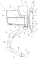
- FIG. 2 is an overall side view of the electric working machine.
- FIG. 2 is a hydraulic circuit diagram provided in the electric work machine.
- the electric work machine 1 of the present invention comprises a battery unit 30, an electric actuator 9 that operates with power supplied by the battery unit 30, and a work device 20 that operates when driven by the electric actuator 9.
- a battery unit 30 an electric actuator 9 that operates with power supplied by the battery unit 30, and a work device 20 that operates when driven by the electric actuator 9.
- FIG 11 is an overall side view of the electric work machine 1.
- the electric work machine 1 is, for example, a backhoe.
- the electric work machine 1 is equipped with a machine body (swivel base) 2, a traveling device 10, a dozer device 18, and a work device 20.
- a driver's seat 4 On top of the machine body 2, there is a driver's seat 4 where an operator sits, and a protection mechanism (cabin) 6 that protects the driver's seat 4 from the front, rear, left, right, and above.
- a protection mechanism (cabin) 6 that protects the driver's seat 4 from the front, rear, left, right, and above.
- a control device 5 for operating the electric work machine 1 is provided around the driver's seat 4 inside the protection mechanism 6 (driver's cab 4R). The operator can operate the control device 5 while seated in the driver's seat 4.
- the protection mechanism 6 is not limited to the cabin shown in FIG. 11, but may be a cabin with a two-post or three-post structure, or may be a canopy.
- the running mechanism 12 is, for example, a crawler type running mechanism.
- the running mechanism 12 has an idler 13, a drive wheel 14, a plurality of rollers 15, an endless crawler belt 16, and running motors ML and MR.
- the machine body 2 is supported on the running frame 11 so that it can rotate around the rotation axis X via the rotation bearing 3.
- a rotation motor MT is provided inside the machine body 2.
- the working device 20 is supported at the front of the machine body 2.
- the working device 20 has a boom 21, an arm 22, a bucket (working tool) 23, and hydraulic cylinders C1 to C5.
- the base end side of the boom 21 is pivotally attached to a swing bracket 24 so as to be rotatable around a horizontal axis (an axis extending in the width direction of the machine body 2). This allows the boom 21 to swing up and down (vertically).
- the electric work machine 1 performs work using the travel device 10, which has the travel motors ML, MR and hydraulic cylinders C1 to C5, the work device 20, and the swing motor MT described above. Hydraulic actuators such as the travel motors ML, MR, the swing motor MT, and the hydraulic cylinders C1 to C5 are included in hydraulic equipment.
- the travel device 10 is also a work device provided on the electric work machine 1.
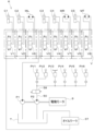
- FIG. 12 shows the hydraulic circuit K provided in the electric work machine 1.
- the hydraulic circuit K includes hydraulic actuators C1-C5, ML, MR, MT, a control valve V, hydraulic pumps P1, P2, a hydraulic oil tank T, an oil cooler 37, control valves PV1-PV6, an unloading valve 58, and an oil passage 50.
- the hydraulic pump P1 draws hydraulic oil stored in the hydraulic oil tank T and then discharges the hydraulic oil toward the control valve V.
- the control hydraulic pump P2 outputs hydraulic pressure for signals, control, etc. by drawing in hydraulic oil stored in the hydraulic oil tank T and then discharging the hydraulic oil. Note that in the example shown in FIG. 12, for convenience, one actuation hydraulic pump P1 and one control hydraulic pump P2 are provided, but any appropriate number may be provided.
- the control valve V has multiple control valves V1 to V8. Each control valve V1 to V8 controls (adjusts) the flow rate of hydraulic oil output from the hydraulic pumps P1 and P2 to each hydraulic actuator C1 to C5, ML, MR, and MT. As a result, the working device 20 is indirectly operated by the driving of the electric actuator 9 via the hydraulic oil discharged by the operating hydraulic pump P1.
- the control valves PV1 to PV6 operate in response to the operation of various control levers 5a (shown in Figure 1) provided on the operating device 5. Pilot oil acts on each control valve V1 to V8 in proportion to the operation amount (operation amount) of each control valve PV1 to PV6, moving the spool of each control valve V1 to V8. Then, an amount of hydraulic oil proportional to the amount the spool of each control valve V1 to V8 is moved is supplied to the hydraulic actuators C1 to C5, ML, MR, and MT to be controlled. Furthermore, each hydraulic actuator C1 to C5, ML, MR, and MT is driven in response to the amount of hydraulic oil supplied from each control valve V1 to V8.
- the unloading valve 58 is a two-position switching valve that can be switched between a supply position and a suppression position.
- the unloading valve 58 supplies hydraulic oil from the oil passage 50 to the operating valves PV1 to PV6.
- the unloading valve 58 stops the supply of hydraulic oil from the oil passage 50 to the operating valves PV1 to PV6, i.e., prohibits or restricts the operation of the hydraulic actuators C1 to C5, ML, MR, and MT.
- the unloading valve 58 is in the supply position, operation of the working device 20 is permitted, and when the unloading valve 58 is in the suppression position, operation of the working device 20 is prohibited or restricted.
- FIG. 1 is an electrical block diagram of the electric work machine 1.
- the operating device 5 of the electric work machine 1 has an operating lever 5a and an operating switch 5b.
- the operating lever 5a and the operating switch 5b can be operated by an operator seated in the driver's seat 4.
- the operating lever 5a and the operating switch 5b are each shown as a single block in FIG. 1, but in reality, multiple operating levers 5a and multiple operating switches 5b are provided.
- the operation switch 5b includes a rotation speed operation device (accelerator dial) 5c for operating the rotation speed (motor rotation speed) of the electric motor 9, and a mode change switch 5d.
- the mode changeover switch 5d is a switch for inputting an instruction to change the control device 7 between the discharge mode and the charge mode.
- the operation switch 5b and the mode changeover switch 5d may be a rotary selector switch or a push button switch that can be operated by pressing.
- the display device 60 described later is a touch panel that can be operated by touch
- the operation switch 5b and the mode changeover switch 5d may be an image (graphical interface) displayed on the display device 60.
- the control device 7 is provided inside the machine body 2 or the protection mechanism 6, and has a CPU 7a and a storage unit 7b.
- the CPU 7a controls the operation of each part of the electric work machine 1 as shown in FIG. 1.
- the storage unit 7b is composed of a memory, etc. Information, data, programs, etc. used by the CPU 7a to control the operation of each part are stored in a readable and writable manner in the storage unit 7b.
- the electric work machine 1 includes an electric actuator 9, an inverter 38, a junction box 39, a DC-DC converter 40, a charging port 41, a charger 45, a battery unit 30, and a low-voltage battery 33.
- the electric actuator 9 operates on power supplied by the battery unit 30.
- the electric actuator 9 is the drive source for the electric work machine 1, and is an electric motor that is, for example, a permanent magnet embedded three-phase AC synchronous motor.
- the inverter 38 is a motor drive device that supplies power from the battery unit 30 to the electric motor 9 to drive the electric motor 9.
- the inverter 38 is electrically connected to the electric motor 9 and the junction box 39.
- the inverter 38 converts the DC power input from the battery unit 30 via the junction box 39 into three-phase AC power, and supplies the three-phase AC power to the electric motor 9. This drives the electric motor 9.
- the inverter 38 can also arbitrarily adjust the current and voltage of the power supplied to the electric motor 9.
- the control device 7 controls the operation of the inverter 38 to drive or stop the electric motor 9.
- the junction box 39 is electrically connected to the inverter 38, the battery unit 30, the DC-DC converter 40, and the charger 45.
- the junction box 39 outputs the power output from the battery unit 30 to the inverter 38 and the DC-DC converter 40.
- the junction box 39 also outputs the power input from the charger 45 to the battery unit 30.
- the DC-DC converter 40 is a voltage conversion device that converts the voltage of the direct current input from the battery unit 30 via the junction box 39 into a different voltage.
- the DC-DC converter 40 is a step-down converter that converts the high voltage of the battery unit 30 into a predetermined low voltage according to the electrical equipment provided in the electric work machine 1.
- the DC-DC converter 40 supplies power to the low-voltage battery 33 after voltage conversion.
- the electrical equipment includes, for example, the control device 7, the display device 60, the oil cooler 37, and the radiator fan motor.
- the charging port 41 has a connector into which the charging cable is fitted and a connection detection sensor 41a.
- the charging port 41 is connected to an external power source (commercial power source, quick charger, etc.) via the charging cable.
- the control device 7 switches to the charging mode when the connection detection sensor 41a detects that a charging cable is connected to the charging port 41, and switches to the discharging mode when the connection detection sensor 41a detects that a charging cable is not connected to the charging port 41.
- control device 7 may switch between the discharge mode and the charge mode not by the mode changeover switch 5d and the connection detection sensor 41a.
- control device 7 may switch to the discharge mode when the starter switch 8 is turned on (to start the electric work machine 1), or switch to the charge mode when the starter switch 8 is not turned on.
- control device 7 may switch to the discharge mode or the charge mode based on the operating state of the operating lever 5a and the operating switch 5b that operate the traveling device 10 and the work device 20.
- the charger 45 is electrically connected to the charging port 41 and the junction box 39, converts three-phase AC power input from an external power source via the charging cable and charging port 41 into DC power, and supplies the DC power to the junction box 39.
- the charger 45 has a rectifier that converts the three-phase AC power into DC power, and an electronic circuit that adjusts the current and voltage of the DC power supplied to the junction box 39.
- the electronic circuit is composed of, for example, switching elements, diodes, resistors, and electrolytic capacitors.
- the charger 45 uses the electronic circuit to adjust the current and voltage of the DC power supplied to the junction box 39, and charges the battery unit 30 by constant current charging or constant voltage charging.
- the current and voltage of the DC power when performing constant current charging or constant voltage charging are defined by a predetermined table stored in the memory unit 7b. The charger 45 adjusts the current and voltage according to a signal from the control device 7.
- the battery unit 30 has a plurality of battery packs 31, 32.
- Each battery pack 31, 32 is a secondary battery (storage battery) such as a lithium ion battery that is composed of at least one battery.
- the plurality of batteries are electrically connected in series and/or parallel.
- the batteries that make up each battery pack 31, 32 have a plurality of cells (battery cells) therein, and the plurality of cells are electrically connected in series and/or parallel.
- Each battery pack 31, 32 has an electrical capacity that can operate each part of the electric work machine 1 for a predetermined period of time. In this embodiment, the battery packs 31, 32 are connected in parallel.
- the battery unit 30 is provided with two battery packs 31, 32, but the number of battery packs in the battery unit 30 is not limited to two, and may be one, or three or more.
- each battery pack 31, 32 is provided with a BMU (battery management unit) 31a, 32a.
- BMU battery management unit
- the BMUs 31a, 32a are provided in the corresponding battery packs 31, 32, but the BMUs 31a, 32a may be built into the corresponding battery packs 31, 32, or may be installed outside the battery packs 31, 32.
- BMU 31a monitors and controls the corresponding battery pack 31.
- BMU 32a monitors and controls the corresponding battery pack 32. Specifically, BMUs 31a and 32a control the opening and closing of relays inside battery packs 31 and 32 to control the start and stop of power supply from battery packs 31 and 32. BMUs 31a and 32a also detect the temperature, voltage, current, and terminal voltage of the internal cells of battery packs 31 and 32.
- BMUs 31a, 32a detect the temperatures of battery packs 31, 32 based on signals detected by temperature detection devices 31b, 31c, 31d, 32b, 32c, 32d provided in battery packs 31, 32, respectively.
- electric work machine 1 is equipped with multiple temperature detection devices 31b, 31c, 31d, 32b, 32c, 32d.
- Multiple temperature detection devices 31b, 31c, 31d, 32b, 32c, 32d are provided in different parts of battery unit 30.
- temperature detection devices 31b, 31c, 31d are arranged in different positions in battery pack 31, and temperature detection devices 32b, 32c, 32d are arranged in different positions in battery pack 32.
- the battery unit 30 has multiple battery cells, and the multiple temperature detection devices 31b, 31c, 31d, 32b, 32c, and 32d are provided in different battery cells.
- each battery pack 31 and 32 has three temperature detection devices, but the number of temperature detection devices that a battery pack has is not limited to three.
- the BMUs 31a and 32a detect the remaining capacity of the battery packs 31 and 32 by a voltage measurement method based on, for example, the terminal voltage of the cells inside the battery packs 31 and 32.
- the method of detecting the remaining capacity of the battery packs 31 and 32 is not limited to the voltage measurement method, and other methods such as a coulomb counter method, a battery cell modeling method, an impedance track method, etc. may also be used.
- a capacity detection unit that detects the remaining capacity of the battery packs 31 and 32 may be provided separately from the BMUs 31a and 32a.
- the low-voltage battery 33 is a storage battery with a lower voltage than the battery unit 30.
- the low-voltage battery 33 is charged with power supplied from the DC-DC converter 40.
- the low-voltage battery 33 supplies power to the electrical equipment of the electric work machine 1.
- the capacity detection device 34 consists of an electrical circuit that detects the remaining capacity of the low-voltage battery 33.
- the electric work machine 1 is also provided with a display device 60.
- the display device 60 is a fixed display device or a tablet-type terminal device capable of displaying images.
- the display device 60 is disposed around the driver's seat 4 inside the protection mechanism 6 (e.g., in front of the operator).
- the display device 60 displays an operation screen showing the motor rotation speed of the electric motor 9, the temperature of the cooling water for cooling the electrical equipment, the oil temperature of the hydraulic oil, etc.
- the discharge control for operating the work device 20 will be described among the control methods for the electric work machine 1 in this embodiment.
- the BMUs 31a and 32a may control relays provided inside the battery packs 31 and 32 or a relay provided in the junction box 39 to discharge at least one battery pack provided in the battery unit 30.
- the charge control described below in this embodiment, the case where the battery packs 31 and 32 are charged simultaneously will be described, but at least one battery pack may be charged.
- the control device 7 limits the discharge current of the battery unit 30 as the temperature of the battery unit 30 increases, thereby limiting the output of the working device 20.
- control device 7 limits the upper limit of the discharge current supplied from the battery unit 30 to a lower value, thereby limiting the output.
- control device 7 may limit the output of the working device 20 by controlling at least one of the rotation speed of the electric motor 9 and the unload valve 58 of the hydraulic circuit K according to the temperature of the battery unit 30.
- the control device 7 controls the second upper limit value I_th2, which is the upper limit value of the discharge current, according to the temperature of the battery unit 30 (second control temperature, hereinafter sometimes referred to as the second temperature for controlling the battery unit 30).
- the second upper limit value I_th2 is defined corresponding to the temperature of the battery unit 30 (second control temperature).
- the control device 7 controls the second upper limit value I_th2 based on a discharge current value map that defines a correspondence between the temperature of the battery unit 30 (second control temperature) and the second upper limit value I_th2.
- the discharge current value map is stored in advance in the memory unit 7b.
- the temperature of the battery unit 30 used by the control device 7 in the discharge control is the maximum or minimum value of the multiple temperature information detected by the temperature detection devices 31b, 31c, 31d, 32b, 32c, and 32d of the battery unit 30.
- the control device 7 obtains the upper limit value of the discharge current corresponding to the maximum temperature T_max and the upper limit value I_th1 of the discharge current corresponding to the minimum temperature T_min from the discharge current value map, and calculates the temperature corresponding to the lower upper limit value of the upper limit value I_th1 of the discharge current corresponding to the maximum temperature T_max and the upper limit value of the discharge current corresponding to the minimum temperature T_min as the second control temperature.
- the second control temperature is not limited to the maximum or minimum value of the multiple temperature information, and may be a value calculated by another calculation method, for example, the maximum value of the multiple temperature information, and is not particularly limited.
- FIG. 2 shows the relationship between the second control temperature and the second upper limit value I_th2.
- the vertical axis shows the second upper limit value I_th2
- the horizontal axis shows the second control temperature.
- the second upper limit value I_th2 is defined as the maximum current value (I_max).
- the second upper limit value I_th2 is defined to fall below I_max as the second control temperature rises.
- the usage limit temperature T_limit is a predetermined value determined by the characteristics of the battery unit 30, and may be, for example, 60 degrees or 70 degrees.
- the second upper limit value I_th2 becomes zero.
- the discharge current value map is stored in advance in the storage unit 7b, but the operator may be able to change the discharge current value map as desired by operating the operation device 5 or the display device 60.
- the discharge current value map is stored in advance in the storage unit 7b as a table-format data structure, but as another example, a software program that converts the relationship between the second control temperature and the second upper limit value I_th2 into a function may be stored in the storage unit 7b. In such a case, in the discharge mode, the CPU 7a of the control device 7 executes the software program to calculate the second upper limit value I_th2 according to the temperature (second control temperature) of the battery unit 30.
- the second upper limit value I_th2 is set to the maximum current value I_max until just before the usage limit temperature T_limit is reached. This allows the electric work machine 1 to continue working while maintaining the maximum power output from the battery unit 30, and to maintain work efficiency.
- the discharge current value map shown in FIG. 2 is merely an example, and if priority is given to not increasing the temperature of the battery unit 30, the second upper limit value I_th2 may be set low even when the second control temperature is low. This makes it possible to suppress deterioration of the battery unit 30.
- FIG. 3 shows a series of steps in discharge control.
- the series of steps shown in FIG. 3 are executed by the CPU 7a based on a software program prestored in the memory unit 7b of the control device 7.
- the control device 7 determines whether the electric work machine 1 is currently in the discharge mode or the charge mode (S31). The control device 7 determines whether the electric work machine 1 is in the discharge mode or the charge mode based on the detection result of whether the connection detection sensor 41a detects whether the charging cable is connected to the charging port 41, or based on the switching state of the mode changeover switch 5d that the operator operates to switch between the discharge mode and the charge mode.
- control device 7 determines that the current mode of the electric work machine 1 is the discharge mode (S31: NO), it acquires the temperature of the battery unit 30 detected by the BMU 31a and BMU 32a (second control temperature) (S32).
- the BMU 31a and BMU 32a calculate the second control temperature based on the temperature information detected by the multiple temperature detection devices 31b, 31c, 31d, 32b, 32c, and 32d, and outputs the calculation result to the control device 7.
- control device 7 obtains the second upper limit value I_th2 based on the detected second control temperature and the discharge current value map stored in the memory unit 7b (S33).
- step S33 the control device 7 outputs an instruction signal to the inverter 38 based on the operation of the operating device 5 (rotation speed operating device 5c) and the second upper limit value I_th2 (S34). At this time, the control device 7 controls the inverter 38 so that the current value of the power supplied to the electric motor 9 via the inverter 38 is equal to or less than the second upper limit value I_th2.
- the control device 7 may control the output of the working device 20 according to the temperature of the battery unit 30 (second control temperature), and may limit the operation of the working device 20 by moving the unload valve 58 from the supply position to the suppression position when the second control temperature reaches the usage limit temperature T_limit. Furthermore, when the second control temperature reaches the usage limit temperature T_limit, the control device 7 may change the instruction signal output to the inverter 38 to reduce the target rotation speed of the electric motor 9 below the target rotation speed corresponding to the operation of the rotation speed operating device 5c, thereby controlling the operation of the working device 20.
- control device 7 determines whether to continue the operation of the working device 20 based on the operation state of the operating lever 5a and the operating switch 5b (S35). If the control device 7 determines that the operation should be continued (S35: YES), it returns to step S32.
- control device 7 determines not to continue the discharge process (S35: NO), it ends this process.
- the control device 7 performs discharge control when the battery unit 30 is in a relatively high temperature state immediately after charging, the battery unit 30 will immediately reach the usage limit temperature T_limit, and the control device 7 will implement the output limit described above to limit the operation of the working device 20 or stop the working device 20. For this reason, in order to perform the intended work without output limit even immediately after charging, it is necessary to charge at a relatively low current value to suppress the temperature rise of the battery unit 30. In other words, the appropriate current value of the charging current for the battery unit 30 differs between a case where it is desired to complete charging in a short time and a case where it is desired to operate the working device 20 without output limit immediately after charging.
- the control device 7 in this embodiment therefore controls the first upper limit value I_th1, which is the upper limit value of the charging current supplied to the battery unit 30, in accordance with the temperature of the battery unit 30. Furthermore, the control device 7 is switchable between a first mode in which the charging current is controlled based on a first correspondence relationship that associates the temperature of the battery unit 30 with the first upper limit value I_th1, and a second mode in which the charging current is controlled based on a second correspondence relationship in which the first upper limit value I_th1 corresponding to at least some temperatures is lower than the first correspondence relationship.
- the control method for the electric operating machine 1 includes a first step of selecting either a predetermined first mode or a second mode, and a second step of controlling a first upper limit value I_th1, which is an upper limit value of the charging current supplied to the battery unit 30, according to the mode selected in the first step and the temperature of the battery unit 30.
- the charging current is controlled based on a first correspondence relationship that associates the temperature of the battery unit 30 with the first upper limit value I_th1
- the charging current is controlled based on a second correspondence relationship in which the first upper limit value I_th1 corresponding to at least some temperatures is lower than the first correspondence relationship.
- the control device 7 controls the upper limit value of the charging current (first upper limit value I_th1) according to the temperature of the battery unit 30 (first control temperature, hereinafter sometimes referred to as the second temperature for controlling the battery unit 30, similar to the second control temperature).
- the first upper limit value I_th1 is defined corresponding to the temperature of the battery unit 30 (first control temperature).
- the control device 7 controls the charging current based on a correspondence relationship (charging current value map) that associates the temperature of the battery unit 30 (first control temperature) with the upper limit value of the charging current (first upper limit value I_th1).
- the charging current value map defines the relationship between the first control temperature and the first upper limit value I_th1, and is stored in advance in the memory unit 7b.
- the temperature of the battery unit 30 used by the control device 7 in charging control is the maximum or minimum value of the multiple temperature information detected by the temperature detection devices 31b, 31c, 31d, 32b, 32c, and 32d of the battery unit 30.
- the control device 7 obtains the upper limit of the charging current corresponding to the highest temperature and the upper limit of the charging current corresponding to the lowest temperature from the charging current value map, and calculates the temperature corresponding to the lower upper limit of the upper limit of the charging current corresponding to the highest temperature and the upper limit of the charging current corresponding to the lowest temperature as the first control temperature.
- the first control temperature is not limited to the maximum or minimum value of the multiple temperature information, and may be a value calculated by another calculation method, for example, the maximum value of the multiple temperature information, and is not particularly limited.
- the charging current value map which is a correspondence relationship (first correspondence relationship, second correspondence relationship) that associates the temperature (first control temperature) of the battery unit 30 in the first mode and the second mode with the first upper limit value I_th1.
- FIG. 4 is a diagram showing the correspondence relationship between the first control temperature and the first upper limit value I_th1.
- the vertical axis indicates the first upper limit value I_th1
- the horizontal axis indicates the first control temperature.
- the first correspondence relationship in the first mode is indicated by M1
- the second correspondence relationship in the second mode is indicated by M2.
- the first mode is a mode that prioritizes shortening the time until charging is completed.
- the first mode is referred to as standard mode M1.
- the second mode is a mode that prioritizes suppressing heat generation of the battery unit 30 during charging.
- the second mode is referred to as heat generation suppression mode M2.
- the heat generation suppression mode M2 corresponds to a case where it is desired to operate the working device 20 without output restrictions even immediately after charging, or a case where the electric working device 1 is charged in an environment where the outside air temperature is relatively high, such as midsummer, and the temperature (first control temperature) of the battery unit 30 is already relatively high. For this reason, at least at some temperatures (for example, the first temperature range R1 shown in FIG. 4), the first upper limit value I_th1 of the heat generation suppression mode M2 is lower than the first upper limit value I_th1 of the standard mode M1.
- the control device 7 lowers the first upper limit value I_th1 as the temperature of the battery unit 30 increases.
- the first upper limit value I_th1 is at a maximum (I_max).
- the first upper limit value I_th1 is lowered (decreased).
- the first upper limit value I_th1 has a monotonically decreasing relationship with the first control temperature.
- heat generation suppression mode M2 the relationship between the first upper limit value I_th1 and the first control temperature also has a monotonically decreasing relationship.
- the first upper limit value I_th1 of the heat generation suppression mode M2 in a predetermined first temperature range R1 of the temperature of the battery unit 30 is lower than the first upper limit value I_th1 of the standard mode M1 in the first temperature range R1. Also, the first upper limit value I_th1 of the heat generation suppression mode M2 in the second temperature range R2, where the temperature of the battery unit 30 is higher than that of the first temperature range R1, is approximately equal to the first upper limit value I_th1 of the standard mode M1 in the second temperature range R2.
- the first upper limit value I_th1 of a predetermined first temperature range R1 is constant with respect to the first control temperature, which is the temperature of the battery unit 30. That is, the first upper limit value I_th1 is constant with respect to the first control temperature and does not always have to become lower (decreasing) as the first control temperature increases, and the first upper limit value I_th1 may be constant in some temperature ranges of the first control temperature. For example, in this embodiment, in the first temperature range R1 where the first control temperature is low, the first upper limit value I_th1 of standard mode M1 is a constant value. Similarly, the first upper limit value I_th1 of heat generation suppression mode M2 is also a constant value.
- FIG. 5 shows an example of the data structure of a charging current value map stored in memory unit 7b.
- Memory unit 7b stores a first control temperature and a first upper limit value I_th1 corresponding to the first control temperature in table format.
- the charging current value map for standard mode M1 is table D1.
- the charging current value map for heat generation suppression mode M2 is table D2.
- the charging current value map is stored in advance in the memory unit 7b, but the operator may be able to change the charging current value map as desired by operating the operation device 5 or the display device 60.
- a software program that converts the relationship between the first control temperature and the first upper limit value I_th1 into a function may be stored in the memory unit 7b. In such a case, in the charge mode of the control device 7, the CPU 7a executes the software program to calculate the first upper limit value I_th1 according to the temperature (first control temperature) of the battery unit 30.
- control device 7 switches (selects) between standard mode M1 and heat generation suppression mode M2.
- the electric work machine 1 is equipped with switches B1, B2, and B3 for switching (selecting) between standard mode M1 and heat suppression mode M2.
- Switches B1, B2, and B3 are, for example, images (graphical interfaces) displayed on the display device 60.
- the control device 7 switches between standard mode M1 and heat suppression mode M2 when a predetermined operation is performed on the operating device 5 and switches B1, B2, and B3 are operated. If the display device 60 is a touch panel that can be operated by touch, the control device 7 may switch between standard mode M1 and heat suppression mode M2 when switches B1, B2, and B3 displayed on the display device 60 are touched.
- FIG. 6 shows an example of a switching screen displayed on the display device 60.
- the control device 7 causes the display device 60 to display the switching screen G1.
- the switching screen G1 includes a message Mg1 (e.g., "Charge mode setting") indicating that this is a screen for performing a switching operation, a message Mg2 (e.g., "Standard") indicating a mode that can be set on the switching screen G1, a message Mg3 (e.g., "Heat suppression"), a switching device (radio button B1, radio button B2, decision button B3), etc.
- the switching device includes radio button B1, radio button B2, and decision button B3. The worker selects the desired mode with radio button B1 and radio button B2 of the switching device, and decides on the selected mode with decision button B3.
- the control device 7 refers to the memory unit 7b and displays the acquired information on the current mode on the display device 60.
- the radio button B2 is black, i.e., on. This indicates that the current setting of the electric operating machine 1 is the heat suppression mode M2.
- the control device 7 causes the display device 60 to display a mode switching indication.
- the control device 7 causes the display device 60 to display a switching indication between on (black) and off (white) for the radio buttons B1 and B2.
- the control device 7 stores the selected mode in the memory unit 7b.
- the switching screen G1 shows that the message Mg3 ("Heat suppression") has been selected.
- the control device 7 stores in the memory unit 7b that the heat suppression mode M2 is selected.
- the configuration of the switching screen G1 is merely an example.
- the user interface may be in a pull-down format.
- the selected mode may be indicated by changing the background color of messages Mg2 and Mg3.
- control device 7 may switch between standard mode M1 and heat suppression mode M2 by voice recognition or image recognition, rather than by a specific operation on the operating device 5. For example, the control device 7 recognizes the voice of the worker obtained from a voice input device, and switches between standard mode M1 and heat suppression mode M2. The control device 7 also recognizes barcodes or characters captured by a camera device, determines which mode to set, and switches between standard mode M1 and heat suppression mode M2.
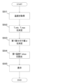
- Figure 7 is a diagram showing a series of steps for charging control by the control device 7.
- the series of processes shown in Figure 7 are executed by the CPU 7a based on a software program previously stored in the memory unit 7b of the control device 7.
- control device 7 determines that the current mode of the electric work machine 1 is the charging mode (FIG. 3, S31: YES), it refers to the memory unit 7b and switches the mode for determining the first upper limit value I_th1 (S71). Specifically, the control device 7 refers to the memory unit 7b, reads whether the current mode is standard mode M1 or heat generation suppression mode M2, and obtains the reference destination of the charging current value map to be referenced when determining the first upper limit value I_th1.
- the control device 7 acquires the first control temperature detected by the BMU 31a and the BMU 32a (S72).
- the BMU 31a and the BMU 32a calculate the first control temperature based on the temperature information detected by the temperature detection devices 31b, 31c, 31d, 32b, 32c, and 32d, and output the calculation result to the control device 7.
- the control device 7 controls the first upper limit value I_th1, which is the upper limit value of the charging current supplied to the battery unit 30, according to the temperature (first control temperature) of the battery unit 30 (S73). In other words, the control device 7 obtains the first upper limit value I_th1, which is the upper limit value of the charging current, based on the first control temperature, information on the current mode, and the charging current value map corresponding to that mode.
- the control device 7 refers to table D2, which is a discharge current value map corresponding to heat generation suppression mode M2, and determines the corresponding first upper limit value I_th1 to be I4.
- the control device 7 refers to table D1, which is a discharge current value map corresponding to standard mode M1, and determines the first upper limit value I_th1 to be I_max.
- the first upper limit value I_th1 in heat generation suppression mode M2 (second mode) is lower than the first upper limit value I_th1 in standard mode M1 (first mode).
- the control device 7 After step S73, the control device 7 outputs an instruction signal of the first upper limit value I_th1 to the charger 45.
- the charger 45 charges the battery unit 30 by adjusting the current of the DC power output to the battery unit 30 so that it is equal to or less than the first upper limit value I_th1 (S74).
- step S74 the control device 7 determines whether to continue charging the battery unit 30 based on the state (remaining capacity) of the battery unit 30 detected by BMU 31a and BMU 32a (S75).
- the control device 7 determines not to continue charging if the remaining capacity of the battery unit 30 is 100%.
- the criteria for determining whether to continue charging may also be switched depending on the current mode. For example, in standard mode M1, the control device 7 determines not to continue charging if the remaining capacity of the battery unit 30 is 100%. On the other hand, in heat generation suppression mode M2, the control device 7 determines not to continue charging if the remaining capacity of the battery unit 30 is 80%.
- the value of the remaining capacity of the battery unit 30, which serves as the criteria for determination is linked to tables D1 and D2 in advance and stored in the memory unit 7b.
- control device 7 determines to continue charging the battery unit 30 (S75: YES), it returns to step S72.
- control device 7 determines that the battery unit 30 will not continue charging (S75: NO), it ends this process.
- the control device 7 controls the current supplied to the battery unit 30 to be reduced, so the time required to complete charging will be longer. Also, at low temperatures, due to the characteristics of the battery, the ability to accept charge is reduced, so the time required to complete charging will be longer. In other words, the time required to charge the battery unit 30 tends to be shorter at medium temperatures and longer at high or low temperatures.
- the display device 60 when the electric work machine 1 is equipped with multiple temperature detection devices 31b, 31c, 31d, 32b, 32c, and 32d, in order for the operator to know an estimate of the charging time of the battery unit 30 from the temperature of the battery unit 30, if the battery unit 30 is relatively hot, it is preferable for the display device 60 to display the highest temperature (maximum value) of the multiple temperatures detected by the temperature detection devices 31b, 31c, 31d, 32b, 32c, and 32d. Similarly, if the battery unit 30 is relatively cold, it is preferable for the display device 60 to display the lowest temperature (minimum value) of the multiple temperatures detected by the temperature detection devices 31b, 31c, 31d, 32b, 32c, and 32d.
- the weighting value used to calculate the first temperature T_show varies depending on the minimum temperature T_min.
- the first weighting value ⁇ which is the weighting value multiplied by the minimum temperature T_min, increases as the minimum temperature decreases
- the second weighting value (1- ⁇ ) which is the weighting value multiplied by the maximum temperature T_max, increases as the minimum temperature increases.
- the control device 7 sets the minimum temperature T_min as the first temperature T_show.
- the second predetermined value th2 may be, for example, 20 degrees or 30 degrees, and is not particularly limited.
- the control device 7 calculates the first temperature T_show, which is the temperature for display, from the minimum temperature T_min, the maximum temperature T_max, and the weighting value.
- control device 7 calculates the first temperature T_show based on the following formula:
- T_show T_min ⁇ +T_max ⁇ (1- ⁇ ) (Formula 1)
- the first weighting value which is a weighting value multiplied by the minimum temperature
- the second weighting value which is a weighting value multiplied by the maximum temperature
- the value 1- ⁇ is the ratio of the minimum temperature T_min to the maximum temperature T_max for the first temperature T_show, which is the temperature to be displayed.
- the first weighting value ⁇ and the second weighting value 1- ⁇ add up to 1. In other words, once the first weighting value ⁇ is determined, the second weighting value 1- ⁇ is also uniquely determined.
- FIG. 8A is a diagram showing the relationship between the first weighting value ⁇ and the minimum temperature T_min.
- the vertical axis indicates the first weighting value ⁇
- the horizontal axis indicates the minimum temperature T_min.
- the first weighting value ⁇ increases as the minimum temperature T_min decreases. In other words, the first weighting value ⁇ and the minimum temperature T_min have a monotonically decreasing relationship.
- the first weighting value ⁇ ranges from 0 to 1 (0 ⁇ 1). If the minimum temperature T_min is less than the first predetermined value th1 (T_min ⁇ th1), the first weighting value ⁇ is set to 1. That is, the formula is as follows.
- T_show T_max (Equation 3)
- the first weighting value ⁇ decreases at a constant rate in the temperature range from the first predetermined value th1 to the second predetermined value th2. That is, it decreases linearly and monotonically (FIG. 8A: 81).
- the amount of change in the first weighting value ⁇ does not have to be constant, and may vary nonlinearly.
- the first weighting value ⁇ may vary as shown in FIG. 8A at 82 or as shown in FIG. 8A at 83.
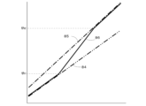
- FIG. 8B is a diagram showing the relationship between the minimum temperature, maximum temperature, and display temperature.
- the minimum temperature T_min (FIG. 8B: 84) is less than the first predetermined value th_1 (T_min ⁇ th1)
- the first temperature T_show (FIG. 8B: 86) is the same as the minimum temperature T_min.
- the difference between the first temperature T_show and the minimum temperature T_min increases as the minimum temperature T_min increases, and the first temperature T_show approaches the maximum temperature T_max.
- the first temperature T_show is the same as the maximum temperature T_max (FIG. 8B: 85).
- the first weighting value ⁇ corresponding to the minimum temperature T_min is stored in advance in the storage unit 7b as a table-format data structure.
- a software program that converts the relationship between the minimum temperature T_min and the first weighting value ⁇ into a function may be stored in the storage unit 7b.
- the control device 7 has the CPU 7a execute the software program to calculate the first weighting value ⁇ corresponding to the minimum temperature T_min.
- the second weighting value 1- ⁇ may be stored in advance in the memory unit 7b as a table-format data structure.
- a software program that converts the relationship between the minimum temperature T_min and the second weighting value 1- ⁇ into a function may be stored in the memory unit 7b. In such a case, the CPU 7a of the control device 7 executes the software program to calculate the second weighting value 1- ⁇ corresponding to the minimum temperature T_min.
- the control device 7 calculates a second temperature for controlling the battery unit 30 separately from the first temperature T_show.
- the second temperature is, for example, the first control temperature in the charge control and/or the second control temperature in the discharge control described above.
- the control device 7 controls at least one of the charge current during charging and the discharge current during discharging of the battery unit 30 based on the second temperature.
- the control device 7 acquires the temperatures detected by BMU 31a and BMU 32a (S91).
- BMU 31a and BMU 32a output the temperature information detected by the multiple temperature detection devices 31b, 31c, 31d, 32b, 32c, and 32d to the control device 7.
- the control device 7 detects the minimum temperature T_min and the maximum temperature T_max from the multiple pieces of temperature information (S92).
- the control device 7 determines the weighting value (S93). Specifically, the control device 7 refers to the memory unit 7b and obtains the first weighting value ⁇ corresponding to the detected minimum temperature T_min. The control device 7 performs a calculation to divide the first weighting value ⁇ from 1, and determines the second weighting value 1- ⁇ .
- the control device 7 calculates the first temperature T_show (S94).
- the first temperature T_show is calculated using the minimum temperature T_min, the maximum temperature T_max, and a weighting value.
- control device 7 causes the display device 60 of the electric operating machine 1 to display the calculated first temperature T_show.
- the control device 7 causes the display device 60 to display, for example, the display screen G2. (S95).
- FIG. 10A shows an example of a display screen.
- Display screen G2 is composed of a battery temperature display section 61 that shows the temperature of the battery unit 30, a battery remaining capacity display section 62 that shows the remaining capacity of the battery unit 30, etc.
- the battery temperature display unit 61 displays the first temperature T_show calculated in S94.
- the battery remaining capacity display unit 62 displays the remaining capacity of the battery unit 30 (e.g., battery packs 31, 32) detected by the BMU 31a.
- the battery remaining capacity display unit 62 displays the remaining capacity of either the battery pack 31 or 32 that has the least remaining capacity.
- the remaining capacity of battery pack 31 is low, so the remaining capacity of battery pack 31 is displayed.
- the battery remaining capacity display unit 62 may switch the remaining capacity of battery packs 31, 32 in accordance with the selection operation of the operating device 5.
- the battery remaining capacity display unit 62 may also display the total remaining capacity of battery packs 31, 32.
- the control device 7 only needs to calculate the first temperature T_show based on the minimum temperature T_min and maximum temperature T_max of the temperatures detected by the multiple temperature detection devices 31b, 31c, 31d, 32b, 32c, and 32d, and a weighting value in which the weight of the minimum temperature increases as the minimum temperature decreases, and the calculation method is not limited to the above-mentioned method.
- the control device 7 may use the average temperature of the temperatures detected by the multiple temperature detection devices 31b, 31c, 31d, 32b, 32c, and 32d as the first temperature T_show when a predetermined temperature is set as the median temperature (reference temperature) and the minimum temperature is the reference temperature.
- the control device 7 calculates the first temperature T_show using the average temperature, the minimum temperature T_min, and the weighting value, and if the minimum temperature is equal to or greater than the reference temperature, the control device 7 calculates the first temperature T_show using the average temperature, the maximum temperature T_max, and the weighting value.
- the first temperature T_show of each of the battery packs 31 and 32 may also be calculated.
- the control device 7 obtains the minimum and maximum temperatures detected by the temperature detection devices 31b, 31c, and 31d of the battery pack 31 from the BMU 31a, and calculates a first temperature T_show for the battery pack 31. As shown in FIG. 10B, the control device 7 causes the display device 60 to display the first temperature T_show for the battery pack 31 on the battery temperature display unit 61a.
- control device 7 obtains the minimum and maximum temperatures detected by the temperature detection devices 32b, 32c, and 32d of the battery pack 32 from the BMU 32a, and calculates the first temperature T_show for the battery pack 32. As shown in FIG. 10B, the control device 7 causes the display device 60 to display the first temperature T_show for the battery pack 32 on the battery temperature display unit 61b.
- the calculated first temperature T_show may be displayed as a numerical value on the display screen.
- the second temperature (first control temperature, second control temperature) of the battery unit 30 in the charge control and discharge control is the temperature corresponding to the lower upper limit value of the maximum temperature and the minimum temperature among the multiple temperature information detected by the multiple temperature detection devices 31b, 31c, 31d, 32b, 32c, 32d, but it may be calculated based on the first predetermined value th1 and the second predetermined value th2.
- the control device 7 controls at least one of the charge current during charging of the battery unit 30 and the discharge current during discharging based on the minimum temperature T_min.
- the control device 7 controls at least one of the charge current and the discharge current based on the maximum temperature T_max.
- the control device 7 controls the charging current based on the minimum temperature T_min as the second temperature (second control temperature). Also, when the maximum temperature T_max detected by the temperature detection devices 31b, 31c, 31d, 32b, 32c, and 32d is equal to or greater than the second predetermined value th2, the control device 7 controls the discharging current based on the maximum temperature T_max as the second temperature (second control temperature).
- the control device 7 controls the discharge current using the minimum temperature T_min as the second temperature (first control temperature).
- the maximum temperature T_max detected by the temperature detection devices 31b, 31c, 31d, 32b, 32c, and 32d is equal to or greater than the second predetermined value th2
- the control device 7 controls the discharge current using the maximum temperature T_max as the second temperature (first control temperature).
- the control device 7 may use the minimum temperature T_min, the maximum temperature T_max, or the average temperature of the minimum temperature T_min and the maximum temperature T_max as the second temperature.
- the standard mode M1 and the heat suppression mode M2 are switched when a specific operation is performed on the operating device 5, i.e., when an operator issues an instruction to do so, but the control device 7 may automatically determine the mode based on specific conditions and switch the mode.
- control device 7 may determine whether to use standard mode M1 or heat suppression mode M2 depending on the current time information. Specifically, for example, if the current time is daytime, it is assumed that the user will want to operate the electric work machine 1 immediately after charging (i.e., to discharge the battery unit 30), so the control device 7 stores in the memory unit 7b that the mode is heat suppression mode M2. On the other hand, if the current time is nighttime, the control device 7 stores in the memory unit 7b that the mode is standard mode M1.
- control device 7 may determine whether to use standard mode M1 or heat generation suppression mode M2 depending on the detection result of the outside air temperature detected by the outside air temperature detection device. Specifically, if the current outside air temperature is higher than a predetermined temperature, it is assumed that the temperature of the battery unit 30 is already high, and therefore the control device 7 stores in the memory unit 7b that the mode is heat generation suppression mode M2.
- the predetermined temperature may be, for example, 30 degrees or 35 degrees.
- the control device 7 stores in the memory unit 7b that the mode is standard mode M1.
- the control device 7 may also determine whether to use standard mode M1 or heat suppression mode M2 depending on the current season. Specifically, the control device 7 determines the current season from date information. If the current season is summer, the outside air temperature is high and it is assumed that the temperature of the battery unit 30 is already high, so the control device 7 stores in the memory unit 7b that the mode is heat suppression mode M2. On the other hand, if the current season is other than summer, the control device 7 stores in the memory unit 7b that the mode is standard mode M1.
- the control device 7 may also determine whether the mode is standard mode M1 or heat suppression mode M2 depending on the area in which the electric work machine 1 is working. Specifically, the control device 7 determines whether the area is relatively high in outside temperature based on area information obtained from a positioning device carried by the electric work machine 1 or set manually by the worker. If the area in which the electric work machine 1 is working is an area in which the outside temperature is relatively high, it is assumed that the temperature of the battery unit 30 is likely to become high. Therefore, the control device 7 stores in the memory unit 7b that the mode is heat suppression mode M2. On the other hand, if the area is not a high outside temperature area, the control device 7 stores in the memory unit 7b that the mode is standard mode M1.
- the control device 7 may also determine whether to use standard mode M1 or heat suppression mode M2 depending on the cumulative operating time that the battery unit 30 has passed current up to now. Specifically, a battery unit 30 whose cumulative operating time is longer than a predetermined time is likely to be degraded. To prevent further deterioration of the battery unit 30, the control device 7 stores in the memory unit 7b that the mode is heat suppression mode M2. On the other hand, if the cumulative battery operating time of the battery unit 30 is shorter than the predetermined time, the control device 7 stores in the memory unit 7b that the mode is standard mode M1.
- the control device 7 may also determine whether to use standard mode M1 or heat suppression mode M2 depending on the most recent power consumption (discharged power) of the electric work machine 1. Specifically, if the operation performed on the electric work machine 1 immediately before charging control required a large power output, there is a high possibility that the next operation will also require a large power output. For this reason, the control device 7 stores in the memory unit 7b that the mode is heat suppression mode M2 so that there is no restriction on the output from the battery unit 30 even immediately after charging. On the other hand, if the most recent power consumption is low, the control device 7 assumes that the next operation will not require a large power output, and stores in the memory unit 7b that the mode is standard mode M1.
- the control device 7 may also determine whether to use standard mode M1 or heat suppression mode M2 depending on the implement attached to the electric work machine 1. Specifically, if the attached implement (hydraulic attachment) requires a large amount of power to operate, there is a high possibility that a large amount of power output will be required when operating the implement immediately after charging. For this reason, the control device 7 stores in the memory unit 7b that the implement is in heat suppression mode M2 so that there is no restriction on the output from the battery unit 30 even immediately after charging. On the other hand, if the attached implement does not require a large amount of power to operate, the control device 7 stores in the memory unit 7b that the implement is in standard mode M1.
- the control device 7 may also determine whether to use standard mode M1 or heat suppression mode M2 depending on the remaining capacity of the battery unit 30 at the start of charging.
- a predetermined value e.g., 80% or more
- the control device 7 stores in the memory unit 7b that the mode is heat suppression mode M2.
- the control device 7 stores in the memory unit 7b that the mode is standard mode M1.
- the control device 7 automatically sets the mode for controlling the first upper limit value I_th1, which is the upper limit value of the charging current, thereby making it possible to improve work efficiency and suppress deterioration of the battery unit 30 at the same time.
- the two modes, the standard mode M1 and the heat generation suppression mode M2 are described as examples.
- the control device 7 only needs to be able to switch between a first mode in which the charging current is controlled based on a predetermined first correspondence relationship, and a second mode in which the charging current is controlled based on a second correspondence relationship in which the first upper limit value I_th1 corresponding to at least some temperatures is lower than the first correspondence relationship.
- the number of modes is not limited to two, and a configuration may be adopted in which the first upper limit value I_th1 is continuously changed by correcting the predetermined first correspondence relationship.
- the electric work machine 1 and the control method for the electric work machine 1 of the first embodiment described above have the following advantages.
- An electric work machine 1 including a battery unit 30, an electric actuator (electric motor) 9 operated by power supplied by the battery unit 30, a work device 20 operated by driving the electric actuator 9, temperature detection devices 31b, 31c, 31d, 32b, 32c, 32d for detecting the temperature of the battery unit 30, and a control device 7 for controlling a first upper limit value I_th1, which is an upper limit value of a charging current supplied to the battery unit 30, according to the temperature of the battery unit 30 (first control temperature), the control device 7 being switchable between a first mode (standard mode M1) for controlling the charging current based on a first correspondence relationship that associates the temperature of the battery unit 30 (first control temperature) with the first upper limit value I_th1, and a second mode (heat generation suppression mode M2) for controlling the charging current based on a second correspondence relationship in which the first upper limit value I_th1 corresponding to at least some temperatures is lower than the first correspondence relationship.
- standard mode M1 for controlling the charging current based on a first correspondence relationship that associates the temperature of the battery unit
- the invention related to item A1 makes it possible to shorten the charging time while suppressing the rise in battery temperature, depending on the application.
- the setting of the first upper limit value I_th1 which is the upper limit value of the charging current that is appropriate for charging in a short time and charging while suppressing the rise in temperature of the battery unit 30, respectively, it is possible to work efficiently.
- the control device 7 of the electric work machine 1 described in Item A1 decreases the first upper limit value I_th1 as the temperature (first control temperature) of the battery unit 30 increases in each of the first and second modes.
- the first upper limit value I_th1 of the first mode and the second mode are approximately the same, while the first upper limit value I_th1 of the first mode and the first upper limit value I_th1 of the second mode in the first temperature section R1 can be made to differ more greatly.
- the charging speed of the battery unit 30 can be kept constant within a certain temperature range.
- the charging control process can be easily implemented.
- the invention related to item A5 enables discharge suited to the temperature characteristics of the battery unit 30.
- the control device 7 reduces the second upper limit value I_th2 as the temperature (second control temperature) of the battery unit 30 increases.
- the electric work machine 1 described in Item A6 The electric work machine 1 described in Item A6.
- the operator can switch between the first mode and the second mode at will, and can perform charging as intended.
- the invention according to item A9 makes it possible to shorten the charging time while suppressing the rise in battery temperature, depending on the application.
- the setting of the first upper limit value I_th1 which is the upper limit value of the charging current suitable for charging in a short time and charging while suppressing the rise in temperature of the battery unit 30, respectively, it is possible to work efficiently.
- An electric work machine 1 including a battery unit 30, an electric actuator (electric motor) 9 that operates with power supplied by the battery unit 30, a work device 20 that operates by driving the electric actuator 9, a plurality of temperature detection devices 31b, 31c, 31d, 32b, 32c, 32d that detect the temperature of the battery unit 30, a control device 7 that calculates a first temperature (temperature for display) T_show of the battery unit 30 based on the temperatures detected by the plurality of temperature detection devices 31b, 31c, 31d, 32b, 32c, 32d, and a display device 60 that displays the first temperature T_show calculated by the control device 7, and the control device 7 calculates the first temperature T_show based on the minimum temperature T_min and maximum temperature T_max of the temperatures detected by the plurality of temperature detection devices 31b, 31c, 31d, 32b, 32c, 32d, and a weighting value that increases the weight of the minimum temperature as the minimum temperature is lower.
- the temperature of the battery unit 30 can be notified in a manner that is easily understandable to the worker.
- the worker can efficiently grasp the temperature of the battery unit 30.
- (Item B2) The electric work machine 1 described in Item B1, in which the control device 7 sets the minimum temperature T_min as the first temperature T_show if the minimum temperature T_min is less than the first predetermined value th1, sets the maximum temperature T_max as the first temperature T_show if the minimum temperature T_min is equal to or greater than the second predetermined value th2, and calculates the first temperature T_show based on the minimum temperature T_min, the maximum temperature T_max, and a weighting value if the minimum temperature T_min is equal to or greater than the first predetermined value th1 and less than the second predetermined value th2.
- the displayed temperature value changes continuously while conforming to the charging characteristics of the battery unit 30, so the worker can grasp the temperature without feeling any discomfort.
- the value of the first temperature T_show changes continuously without sudden changes, so the worker can easily grasp the temperature of the battery unit 30.
- Item B4 An electric operating machine 1 described in any one of Items B1 to B3, in which the temperature detection devices 31b, 31c, 31d, 32b, 32c, and 32d are provided in different parts of the battery unit 30.
- the temperature of the battery unit 30 can be accurately notified to the worker.
- the battery unit 30 has multiple battery cells, and the multiple temperature detection devices 31b, 31c, 31d, 32b, 32c, and 32d are provided in different battery cells.
- the electric work machine 1 is described in items B1 to B4.
- the temperature of the battery unit 30 can be accurately notified to the worker.
- (Item B6) An electric operating machine 1 described in any one of items B1 to B5, in which the control device 7 controls at least one of the charging current during charging and the discharging current during discharging of the battery unit 30 based on the minimum temperature T_min when the minimum temperature T_min is less than a first predetermined value th1, and controls at least one of the charging current and the discharging current during discharging based on the maximum temperature T_max when the maximum temperature T_max is equal to or greater than a second predetermined value th2.
- the invention related to item B6 enables charging and/or discharging suitable for the temperature characteristics of the battery unit 30.
- the control device 7 calculates a second temperature for controlling the battery unit 30 separately from the first temperature T_show, and controls at least one of the charging current during charging of the battery unit 30 and the discharging current during discharging of the battery unit 30 based on the second temperature.
- the upper limit values of the charging current and discharging current are defined in accordance with the temperature of the battery unit 30, and the control device 7 calculates the temperature corresponding to the lower upper limit value of the maximum temperature T_max and the minimum temperature T_min as the second temperature.
- the invention according to item B8 makes it possible to charge and/or discharge the battery unit 30 in a manner suitable for the temperature characteristics of the battery unit 30 more reliably, whether the temperature of the battery unit 30 is relatively low or relatively high.
- the temperature of the battery unit 30 can be notified in a manner that is easily understandable to the worker.
- the worker can efficiently grasp the temperature of the battery unit 30.
- the present invention is applied to an electric work machine 1 such as a backhoe, but the application of the present invention is not limited to this, and it may be applied to other construction machines such as wheel loaders, compact track loaders, and skid steer loaders, and may be applied to agricultural machines such as tractors, combine harvesters, rice transplanters, and lawn mowers.
- Electric work machine 7 Control device 9: Electric actuator (electric motor) 20: Working device 30: Battery unit 31: Battery pack 31b: Temperature detection device 31c: Temperature detection device 31d: Temperature detection device 32: Battery pack 32b: Temperature detection device 32c: Temperature detection device 32d: Temperature detection device M1: First mode (standard mode) M2: Second mode (heat suppression mode) I_th1: First upper limit value (upper limit value of charging current) I_th2: second upper limit value (upper limit value of discharge current) R1: First temperature section R2: Second temperature section B1: Switch (radio button) B2: Switch (radio button) B3: Switch (decision button)
Landscapes
- Engineering & Computer Science (AREA)
- Power Engineering (AREA)
- Mining & Mineral Resources (AREA)
- Civil Engineering (AREA)
- General Engineering & Computer Science (AREA)
- Structural Engineering (AREA)
- Manufacturing & Machinery (AREA)
- Chemical & Material Sciences (AREA)
- Chemical Kinetics & Catalysis (AREA)
- Electrochemistry (AREA)
- General Chemical & Material Sciences (AREA)
- Charge And Discharge Circuits For Batteries Or The Like (AREA)
- Secondary Cells (AREA)
Priority Applications (3)
| Application Number | Priority Date | Filing Date | Title |
|---|---|---|---|
| JP2025529519A JPWO2025004612A1 (https=) | 2023-06-27 | 2024-05-21 | |
| EP24831484.1A EP4737649A1 (en) | 2023-06-27 | 2024-05-21 | Electric work machine and method for controlling electric work machine |
| US19/418,490 US20260103872A1 (en) | 2023-06-27 | 2025-12-12 | Electric working machine and method of controlling electric working machine |
Applications Claiming Priority (2)
| Application Number | Priority Date | Filing Date | Title |
|---|---|---|---|
| JP2023-105373 | 2023-06-27 | ||
| JP2023105373 | 2023-06-27 |
Related Child Applications (1)
| Application Number | Title | Priority Date | Filing Date |
|---|---|---|---|
| US19/418,490 Continuation US20260103872A1 (en) | 2023-06-27 | 2025-12-12 | Electric working machine and method of controlling electric working machine |
Publications (1)
| Publication Number | Publication Date |
|---|---|
| WO2025004612A1 true WO2025004612A1 (ja) | 2025-01-02 |
Family
ID=93938525
Family Applications (1)
| Application Number | Title | Priority Date | Filing Date |
|---|---|---|---|
| PCT/JP2024/018637 Ceased WO2025004612A1 (ja) | 2023-06-27 | 2024-05-21 | 電動作業機、及び電動作業機の制御方法 |
Country Status (4)
| Country | Link |
|---|---|
| US (1) | US20260103872A1 (https=) |
| EP (1) | EP4737649A1 (https=) |
| JP (1) | JPWO2025004612A1 (https=) |
| WO (1) | WO2025004612A1 (https=) |
Citations (6)
| Publication number | Priority date | Publication date | Assignee | Title |
|---|---|---|---|---|
| JP2008069516A (ja) * | 2006-09-12 | 2008-03-27 | Hitachi Constr Mach Co Ltd | 電動式建設機械 |
| JP2009114653A (ja) * | 2007-11-02 | 2009-05-28 | Hitachi Constr Mach Co Ltd | 電気駆動式建設機械 |
| WO2015015647A1 (ja) * | 2013-08-02 | 2015-02-05 | 株式会社小松製作所 | 作業車両 |
| JP2020115715A (ja) * | 2019-01-17 | 2020-07-30 | トヨタ自動車株式会社 | 車両および車両の制御方法 |
| JP2021080703A (ja) | 2019-11-18 | 2021-05-27 | 株式会社クボタ | 電動作業機 |
| WO2022270010A1 (ja) * | 2021-06-22 | 2022-12-29 | 株式会社クボタ | 電動作業機および電動作業機の充電システム |
-
2024
- 2024-05-21 JP JP2025529519A patent/JPWO2025004612A1/ja active Pending
- 2024-05-21 EP EP24831484.1A patent/EP4737649A1/en active Pending
- 2024-05-21 WO PCT/JP2024/018637 patent/WO2025004612A1/ja not_active Ceased
-
2025
- 2025-12-12 US US19/418,490 patent/US20260103872A1/en active Pending
Patent Citations (6)
| Publication number | Priority date | Publication date | Assignee | Title |
|---|---|---|---|---|
| JP2008069516A (ja) * | 2006-09-12 | 2008-03-27 | Hitachi Constr Mach Co Ltd | 電動式建設機械 |
| JP2009114653A (ja) * | 2007-11-02 | 2009-05-28 | Hitachi Constr Mach Co Ltd | 電気駆動式建設機械 |
| WO2015015647A1 (ja) * | 2013-08-02 | 2015-02-05 | 株式会社小松製作所 | 作業車両 |
| JP2020115715A (ja) * | 2019-01-17 | 2020-07-30 | トヨタ自動車株式会社 | 車両および車両の制御方法 |
| JP2021080703A (ja) | 2019-11-18 | 2021-05-27 | 株式会社クボタ | 電動作業機 |
| WO2022270010A1 (ja) * | 2021-06-22 | 2022-12-29 | 株式会社クボタ | 電動作業機および電動作業機の充電システム |
Also Published As
| Publication number | Publication date |
|---|---|
| EP4737649A1 (en) | 2026-05-06 |
| US20260103872A1 (en) | 2026-04-16 |
| JPWO2025004612A1 (https=) | 2025-01-02 |
Similar Documents
| Publication | Publication Date | Title |
|---|---|---|
| JP7676546B2 (ja) | 電動作業機および電動作業機の充電システム | |
| US9745723B2 (en) | Construction machine and battery pack thereof | |
| US9744962B2 (en) | Hybrid construction machine | |
| US12231036B2 (en) | Work machine | |
| US20130174556A1 (en) | Hybrid construction machine | |
| EP4265851A1 (en) | Electric work machine | |
| US10329737B2 (en) | Hybrid construction machine | |
| WO2025004612A1 (ja) | 電動作業機、及び電動作業機の制御方法 | |
| WO2025004613A1 (ja) | 電動作業機、及び電動作業機の制御方法 | |
| US20250003193A1 (en) | Working machine | |
| KR20240125437A (ko) | 작업 기계의 제어 방법, 작업 기계용 제어 프로그램, 작업 기계용 제어 시스템 및 작업 기계 | |
| JP2024052189A (ja) | 建設機械 | |
| JP6695231B2 (ja) | ハイブリッド式建設機械 | |
| WO2026004283A1 (ja) | 電動作業機 | |
| WO2026004282A1 (ja) | 電動作業機 | |
| JP7711310B2 (ja) | 電動作業機 | |
| JP2024094640A (ja) | 電動作業機、及び電動作業機の制御方法 | |
| JP7779976B1 (ja) | 電動式建設機械 | |
| JP7711309B2 (ja) | 電動作業機 | |
| JP2024094639A (ja) | 電動作業機、及び電動作業機の制御方法 | |
| WO2026004281A1 (ja) | 電動作業機 | |
| JP2024094638A (ja) | 電動作業機、及び電動作業機の制御方法 |
Legal Events
| Date | Code | Title | Description |
|---|---|---|---|
| 121 | Ep: the epo has been informed by wipo that ep was designated in this application |
Ref document number: 24831484 Country of ref document: EP Kind code of ref document: A1 |
|
| ENP | Entry into the national phase |
Ref document number: 2025529519 Country of ref document: JP Kind code of ref document: A |
|
| WWE | Wipo information: entry into national phase |
Ref document number: 2025529519 Country of ref document: JP |
|
| WWE | Wipo information: entry into national phase |
Ref document number: 2024831484 Country of ref document: EP |
|
| NENP | Non-entry into the national phase |
Ref country code: DE |
|
| ENP | Entry into the national phase |
Ref document number: 2024831484 Country of ref document: EP Effective date: 20260127 |
|
| ENP | Entry into the national phase |
Ref document number: 2024831484 Country of ref document: EP Effective date: 20260127 |