WO2025004531A1 - 撮像制御装置、撮像制御システム、撮像制御方法、及びプログラム - Google Patents
撮像制御装置、撮像制御システム、撮像制御方法、及びプログラム Download PDFInfo
- Publication number
- WO2025004531A1 WO2025004531A1 PCT/JP2024/016860 JP2024016860W WO2025004531A1 WO 2025004531 A1 WO2025004531 A1 WO 2025004531A1 JP 2024016860 W JP2024016860 W JP 2024016860W WO 2025004531 A1 WO2025004531 A1 WO 2025004531A1
- Authority
- WO
- WIPO (PCT)
- Prior art keywords
- imaging
- condition
- control
- positional relationship
- control device
- Prior art date
- Legal status (The legal status is an assumption and is not a legal conclusion. Google has not performed a legal analysis and makes no representation as to the accuracy of the status listed.)
- Ceased
Links
Images



Classifications
-
- H—ELECTRICITY
- H04—ELECTRIC COMMUNICATION TECHNIQUE
- H04N—PICTORIAL COMMUNICATION, e.g. TELEVISION
- H04N23/00—Cameras or camera modules comprising electronic image sensors; Control thereof
- H04N23/60—Control of cameras or camera modules
-
- G—PHYSICS
- G03—PHOTOGRAPHY; CINEMATOGRAPHY; ANALOGOUS TECHNIQUES USING WAVES OTHER THAN OPTICAL WAVES; ELECTROGRAPHY; HOLOGRAPHY
- G03B—APPARATUS OR ARRANGEMENTS FOR TAKING PHOTOGRAPHS OR FOR PROJECTING OR VIEWING THEM; APPARATUS OR ARRANGEMENTS EMPLOYING ANALOGOUS TECHNIQUES USING WAVES OTHER THAN OPTICAL WAVES; ACCESSORIES THEREFOR
- G03B15/00—Special procedures for taking photographs; Apparatus therefor
-
- G—PHYSICS
- G03—PHOTOGRAPHY; CINEMATOGRAPHY; ANALOGOUS TECHNIQUES USING WAVES OTHER THAN OPTICAL WAVES; ELECTROGRAPHY; HOLOGRAPHY
- G03B—APPARATUS OR ARRANGEMENTS FOR TAKING PHOTOGRAPHS OR FOR PROJECTING OR VIEWING THEM; APPARATUS OR ARRANGEMENTS EMPLOYING ANALOGOUS TECHNIQUES USING WAVES OTHER THAN OPTICAL WAVES; ACCESSORIES THEREFOR
- G03B17/00—Details of cameras or camera bodies; Accessories therefor
- G03B17/56—Accessories
-
- G—PHYSICS
- G06—COMPUTING OR CALCULATING; COUNTING
- G06T—IMAGE DATA PROCESSING OR GENERATION, IN GENERAL
- G06T7/00—Image analysis
- G06T7/20—Analysis of motion
- G06T7/246—Analysis of motion using feature-based methods, e.g. the tracking of corners or segments
-
- G—PHYSICS
- G06—COMPUTING OR CALCULATING; COUNTING
- G06T—IMAGE DATA PROCESSING OR GENERATION, IN GENERAL
- G06T7/00—Image analysis
- G06T7/60—Analysis of geometric attributes
-
- H—ELECTRICITY
- H04—ELECTRIC COMMUNICATION TECHNIQUE
- H04N—PICTORIAL COMMUNICATION, e.g. TELEVISION
- H04N23/00—Cameras or camera modules comprising electronic image sensors; Control thereof
- H04N23/60—Control of cameras or camera modules
- H04N23/61—Control of cameras or camera modules based on recognised objects
- H04N23/611—Control of cameras or camera modules based on recognised objects where the recognised objects include parts of the human body
-
- H—ELECTRICITY
- H04—ELECTRIC COMMUNICATION TECHNIQUE
- H04N—PICTORIAL COMMUNICATION, e.g. TELEVISION
- H04N23/00—Cameras or camera modules comprising electronic image sensors; Control thereof
- H04N23/60—Control of cameras or camera modules
- H04N23/64—Computer-aided capture of images, e.g. transfer from script file into camera, check of taken image quality, advice or proposal for image composition or decision on when to take image
-
- H—ELECTRICITY
- H04—ELECTRIC COMMUNICATION TECHNIQUE
- H04N—PICTORIAL COMMUNICATION, e.g. TELEVISION
- H04N23/00—Cameras or camera modules comprising electronic image sensors; Control thereof
- H04N23/60—Control of cameras or camera modules
- H04N23/66—Remote control of cameras or camera parts, e.g. by remote control devices
- H04N23/661—Transmitting camera control signals through networks, e.g. control via the Internet
- H04N23/662—Transmitting camera control signals through networks, e.g. control via the Internet by using camera arrangements where one camera controls another camera to affect the control of camera image capture, e.g. placing the camera in a desirable condition to capture a desired image
-
- H—ELECTRICITY
- H04—ELECTRIC COMMUNICATION TECHNIQUE
- H04N—PICTORIAL COMMUNICATION, e.g. TELEVISION
- H04N23/00—Cameras or camera modules comprising electronic image sensors; Control thereof
- H04N23/60—Control of cameras or camera modules
- H04N23/69—Control of means for changing angle of the field of view, e.g. optical zoom objectives or electronic zooming
-
- H—ELECTRICITY
- H04—ELECTRIC COMMUNICATION TECHNIQUE
- H04N—PICTORIAL COMMUNICATION, e.g. TELEVISION
- H04N23/00—Cameras or camera modules comprising electronic image sensors; Control thereof
- H04N23/60—Control of cameras or camera modules
- H04N23/695—Control of camera direction for changing a field of view, e.g. pan, tilt or based on tracking of objects
-
- H—ELECTRICITY
- H04—ELECTRIC COMMUNICATION TECHNIQUE
- H04N—PICTORIAL COMMUNICATION, e.g. TELEVISION
- H04N23/00—Cameras or camera modules comprising electronic image sensors; Control thereof
- H04N23/90—Arrangement of cameras or camera modules, e.g. multiple cameras in TV studios or sports stadiums
Definitions
- the present invention relates to an imaging control device, an imaging control system, an imaging control method, and a program.
- Sports scenes are captured by cameramen. Meanwhile, the automation of capturing sports scenes is progressing. For example, a technology is known in which multiple cameras are remotely linked and commanded to capture images simultaneously. A system has also been proposed that broadcasts a soccer field while automatically changing the angle of view and zoom. An imaging device is also known that has a function to track the angle of view to a specified subject (Patent Document 1).
- One aspect of the present invention is an imaging control device that includes an acquisition unit that acquires a positional relationship between a first object and a second object, and a control unit that controls imaging of at least one of the first object and the second object by an imaging device, and the control unit controls imaging by the imaging device when the positional relationship acquired by the acquisition unit satisfies a predetermined imaging condition.
- One aspect of the present invention is an imaging control system that includes the imaging control device described above and an imaging device controlled by the imaging control device.
- One aspect of the present invention is an imaging control method that includes an acquisition step of acquiring a positional relationship between a first object and a second object, and a control step of controlling imaging of at least one of the first object and the second object by an imaging device, and the control step controls imaging by the imaging device when the positional relationship acquired in the acquisition step satisfies a predetermined imaging condition.
- One aspect of the present invention is a program for causing a computer to execute an acquisition step of acquiring a positional relationship between a first object and a second object, and a control step of controlling an image capture by an imaging device of at least one of the first object and the second object, the control step controlling the imaging by the imaging device when the positional relationship acquired in the acquisition step satisfies a predetermined imaging condition.
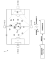
- FIG. 1 is a diagram illustrating an example of a configuration of an imaging control system 1 according to a first embodiment.
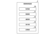
- 2 is a diagram illustrating an example of a functional configuration of an imaging control device 2 according to a first embodiment.
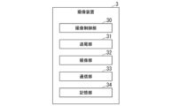
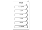
- 2 is a diagram illustrating an example of a functional configuration of an imaging device 3 according to a first embodiment.
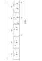
- FIG. 4 is a diagram for explaining an example of an imaging condition according to the first embodiment.
- FIG. 4 is a diagram for explaining an example of an imaging condition according to the first embodiment.
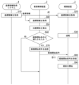
- 4 is a diagram showing an example of a flow of control by the imaging control system 1 at the start of imaging according to the first embodiment.
- FIG. 11 is a diagram showing an example of a flow of control by the imaging control system 1 at the end of imaging according to the first embodiment.
- FIG. 11 is a diagram for explaining another example of the imaging conditions according to the modified example of the first embodiment.
- FIG. 11 is a diagram illustrating an example of a functional configuration of an imaging control system 1a according to a second embodiment.
- FIG. 11 is a diagram illustrating an example of a functional configuration of an imaging device 3a according to a second embodiment.
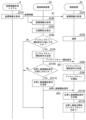
- FIG. 11 is a diagram showing an example of a flow of control by the imaging control system 1a at the start of imaging according to the second embodiment.
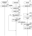
- FIG. 13 is a diagram showing another example of the flow of control by the imaging control system 1a at the start of imaging according to the modified example of the second embodiment.
- FIG. 1 is a diagram showing an example of the configuration of an imaging control system 1 according to this embodiment.
- the imaging control system 1 includes an imaging control device 2, a plurality of imaging devices 3, and a coordinate information acquisition system 4.
- the plurality of imaging devices 3 are composed of four imaging devices: a first imaging device 3-1, a second imaging device 3-2, a third imaging device 3-3, and a fourth imaging device 3-4.
- one of the plurality of imaging devices 3 will be referred to as the imaging device 3.
- the imaging control system 1 is a system that automatically captures a specific scene of a player of interest (also referred to as a featured player) playing a sport as a series of still images.
- the sport is soccer, as an example.
- a specific scene is a decisive scene or a noteworthy scene in a soccer game, such as a goal-scoring scene or a shooting scene.
- the imaging control device 2 controls imaging by each of the multiple imaging devices 3.
- the imaging control device 2 controls the imaging by transmitting an imaging control signal B1 to each of the multiple imaging devices 3.
- the imaging control device 2 controls imaging by each of the multiple imaging devices 3 by remote control.
- One example of the imaging control device 2 is a personal computer (Personal Computer: PC).
- the imaging control device 2 may transmit the imaging control signal B1 to the imaging devices 3 wirelessly, or may transmit the imaging control signal B1 via a wired connection.
- the imaging control device 2 acquires coordinate information A1 supplied from the coordinate information acquisition system 4.
- the imaging control device 2 calculates the positional relationship between the first object and the second object captured by the imaging device 3 based on the coordinate information A1.
- the imaging control device 2 controls the imaging by each of the multiple imaging devices 3 when the positional relationship satisfies a predetermined imaging condition.
- the first object is, for example, a featured player.
- the second object is a ball. Either the first object or the second object may be a referee.
- the second object may also be a fixed object.
- a fixed object is, for example, a goal post or a white line representing a penalty area.
- the imaging device 3 captures images of sports scenes.
- Each of the multiple imaging devices 3 tracks and captures a featured player.
- each of the multiple imaging devices 3 tracks and captures a common featured player.
- the featured player is determined in advance.
- the featured player is, for example, a striker or a star player.
- the imaging operation of the imaging device 3 is remotely controlled by the imaging control device 2.
- the imaging operation performed by the imaging device 3 includes panning, tilting, and zooming.
- the imaging device 3 is a pan-tilt-zoom (PTZ) camera.
- the imaging device 3 may be composed of a camera (e.g., a mirrorless camera) and a remotely controllable camera platform.
- the imaging control device 2 controls imaging by each of the multiple imaging devices 3 provided separately from the imaging control device 2.
- the imaging control device 2 and the imaging devices 3 may be configured as an integrated device.
- the imaging device 3 outputs the captured image C1 to the imaging control device 2.
- the imaging control device 2 displays a video (also referred to as a live view) in which the imaging device 3 automatically tracks the noted player.
- the captured image C1 includes multiple still images of a specific scene that have been continuously shot.
- the multiple still images of a specific scene that have been continuously shot are images captured under the control of the imaging control device 2 when the positional relationship between a first object and a second object captured by the imaging device 3 satisfies a predetermined imaging condition.
- the imaging device 3 may output the captured image C1 to a server that is communicably connected via a network.
- the coordinate information acquisition system 4 acquires coordinate information A1 for each of the one or more objects.
- the coordinate information A1 is information indicating coordinates showing the position of each of the one or more objects.
- the coordinate information A1 is acquired for each of the one or more people playing a sport.
- the coordinate information A1 includes information identifying the object and information indicating coordinates showing the object's position on the pitch.
- the coordinates showing the position on the pitch are indicated by, for example, two-dimensional Cartesian coordinates.
- the information identifying the object is, for example, the uniform number of a player on each team.
- the coordinate information acquisition system 4 is a tracking system consisting of a camera and a server.
- the coordinate information acquisition system 4 acquires coordinate information A1 for each object from images captured by multiple cameras installed in positions that can capture the pitch.
- the cameras may be ceiling cameras attached to the ceiling of the stadium, or cameras attached to a drone.
- the number of cameras may be a single device rather than multiple devices.
- the coordinate information acquisition system 4 calculates coordinate information A1 for each object based on image recognition from the images captured by the multiple cameras.
- the coordinate information acquisition system 4 acquires coordinate information A1 instantly (in real time) during the period when the sport is being played.
- the multiple cameras may be imaging devices 3, or may be installed separately from the imaging devices 3.
- the imaging device 3 When the imaging device 3 is used as a camera to acquire the coordinate information A1, the imaging device 3 acquires the coordinate information A1 based on the position where the imaging device 3 is installed, the direction in which the imaging device 3 captures images, and information on the distance from the imaging device 3 to the object.
- the coordinate information acquisition system 4 may acquire not only the coordinate information A1 from the captured image, but also the moving speed, acceleration, and moving direction of the object.
- the coordinate information A1 includes information indicating the coordinates, as well as information indicating the moving speed, acceleration, and moving direction of the object.
- FIG. 2 is a diagram showing an example of the functional configuration of the imaging control device 2 according to this embodiment.
- the imaging control device 2 includes an acquisition unit 20, a control unit 21, a communication unit 22, a display unit 23, and a storage unit 24.
- the acquisition unit 20 acquires coordinate information A1 from the coordinate information acquisition system 4. Based on the acquired coordinate information A1, the acquisition unit 20 calculates the positional relationship between the first object and the second object captured by the imaging device 3. The acquisition unit 20 acquires the positional relationship by calculating the positional relationship. Thus, the acquisition unit 20 acquires the positional relationship between the first object and the second object captured by the imaging device 3.
- the first object is a player playing soccer
- the second object is a ball. Therefore, the first object is a person, and the second object is a non-person.
- the control unit 21 controls the imaging by the imaging device 3.
- the control unit 21 controls the imaging by the imaging device 3 when the positional relationship between the first object and the second object satisfies a predetermined imaging condition.
- the control unit 21 controls the imaging of at least one of the first object and the second object by the imaging device 3.
- the control unit 21 controls the imaging by each of the multiple imaging devices 3 provided separately from the imaging control device 2.
- the positional relationship between the first object and the second object is the distance between the first object and the second object.
- the positional relationship between the player and the ball is the distance between the player and the ball.
- the distance between the player and the ball is the distance on the pitch.
- the distance between the first object and the second object is the distance within the space in which the first object and the second object exist.
- the distance within the space is, in other words, the physical distance.
- the control unit 21 controls the imaging by the imaging device 3 when the distance between the first object and the second object is equal to or less than a predetermined distance.
- a ceiling camera installed in a position where it can image the pitch may calculate the positional relationship between the first object and the second object without basing it on the coordinate information A1.
- the ceiling camera calculates the positional relationship, it measures the distance to the first object and the distance to the second object, respectively, and calculates the positional relationship using the measured distance information and information on the height at which the ceiling camera is installed.
- the acquisition unit 20 and the control unit 21 are each realized, for example, by the CPU loading a program read from a ROM (Read Only Memory) into a RAM (Random Access Memory) and executing processing according to the program.
- the ROM and RAM are included in the storage unit 24.
- the communication unit 22 transmits and receives various types of information via the wireless network. For example, the communication unit 22 transmits an imaging control signal B1 to the imaging device 3. The communication unit 22 receives an image C1 from the imaging device 3. The communication unit 22 includes a communication interface (I/F) for performing wireless communication.
- I/F communication interface
- the display unit 23 displays various types of information.
- the display unit 23 displays the captured image C1 acquired from the imaging device 3.
- a user of the imaging control system 1 can view or check the captured image C1 captured by the imaging device 3 by displaying it on the display unit 23.
- the display unit 23 includes, for example, a liquid crystal display or an organic electroluminescence (EL: Electro-Luminescence) display.
- the storage unit 24 stores various types of information.
- the storage unit 24 stores predetermined imaging conditions that the control unit 21 uses to control imaging by the imaging device 3.
- the storage unit 24 also stores the captured image C1 acquired from the imaging device 3.
- the storage unit 24 is configured using a storage device such as a magnetic hard disk device or a semiconductor storage device.
- FIG. 3 is a diagram showing an example of the functional configuration of the imaging device 3 according to this embodiment.
- the imaging device 3 includes an imaging control unit 30, a tracking unit 31, an imaging unit 32, a communication unit 33, and a storage unit 34.
- the imaging control unit 30 controls the imaging unit 32.
- the imaging control unit 30 causes the imaging unit 32 to perform panning, tilting, and zooming.
- the imaging control unit 30 controls the imaging direction of the imaging unit 32 so that the object imaged by the imaging unit 32 is within the angle of view.
- the imaging control unit 30 is remotely controlled by the imaging control device 2.
- the tracking unit 31 tracks an object captured by the imaging device 3.
- the tracking unit 31 tracks the object based on coordinate information indicating the coordinates in space of the first object or the second object.
- the tracking unit 31 acquires coordinate information A1 from the coordinate information acquisition system 4 as the coordinate information.
- the tracking unit 31 calculates the direction and angle of view for the tracked object to enter the angle of view of the imaging unit 32 based on the coordinate information.
- the imaging control unit 30 causes the imaging unit 32 to pan, tilt, and zoom based on the direction and angle of view calculated by the tracking unit 31.
- the imaging unit 32 is controlled by the imaging control unit 30 to capture an image of the object. This image is referred to as a captured image C1.
- the imaging unit 32 includes an optical system and an imaging element.
- the optical system includes mechanisms for panning, tilting, and zooming.
- the captured image C1 is a still image.
- the imaging unit 32 is controlled by the imaging control unit 30 to continuously capture a plurality of still images during the period from the start of imaging to the end of imaging. In other words, the imaging unit 32 captures still images continuously.
- the continuous shooting speed may be, for example, about one to two frames per second.
- the continuous shooting speed may be faster than about one to two frames per second.
- the image captured by the imaging unit 32 may be a video.
- the communication unit 33 transmits and receives various types of information via the wireless network. For example, the communication unit 33 receives an imaging control signal B1 from the imaging control device 2. The communication unit 33 transmits an image C1 to the imaging control device 2. The communication unit 33 also receives coordinate information A1 from the coordinate information acquisition system 4. The communication unit 33 includes a communication interface (I/F) for performing wireless communication.
- I/F communication interface
- the storage unit 34 stores various types of information.
- the storage unit 34 stores the captured image C1.
- the storage unit 24 is configured using, for example, a memory card.
- the coordinate information A1 supplied from the coordinate information acquisition system 4 is also used by the acquisition unit 20 provided in the imaging control device 2 to acquire the positional relationship between the first object and the second object. Therefore, the imaging device 3 tracks an object based on the coordinate information A1 indicating the coordinates in space of the first object or the second object, and the acquisition unit 20 acquires the positional relationship between the first object and the second object based on the coordinates of the first object and the coordinates of the second object indicated by the coordinate information A1 used to track the object.
- the imaging device 3 may further calculate the positional relationship between the first object and the second object using the acquired coordinate information A1.
- the acquisition unit 20 acquires the positional relationship between the first object and the second object calculated by the imaging device 3.
- the imaging control system 1 may also include a system for acquiring coordinate information used by the tracking unit 31 for tracking, separate from the coordinate information acquisition system 4.
- the tracking unit 31 may also perform tracking based on image recognition instead of coordinate information.
- the tracking unit 31 may track the ball instead of the player.
- the imaging device 3 has a function of tracking the first object or the second object.
- the control unit 21 provided in the imaging control device 2 controls imaging by the imaging device 3 having the tracking function.
- the imaging device 3 does not necessarily have to have a function of tracking the first object or the second object. In that case, the tracking unit 31 is omitted from the configuration of the imaging device 3.
- a zoomed image of the noted player may be generated using digital zoom. In this case, it is sufficient for the noted player to be within the angle of view when being tracked.
- FIG. 4 and 5 are diagrams for explaining an example of the imaging conditions according to this embodiment.
- the control unit 21 provided in the imaging control device 2 controls imaging by the imaging device 3 when the distance between the player and the ball is equal to or less than a predetermined distance.
- the control of imaging by the imaging device 3 is the start of imaging or the end of imaging.
- the predetermined distance or less is, for example, 5 meters or less.
- the ten images from image P1 to image P10 shown in Figures 4 and 5 are images of soccer scenes arranged in chronological order within the angle of view of the imaging device 3.
- the player that the imaging device 3 is tracking is the noted player X1.
- images P1 and P2 the distance between the noted player X1 and the ball Y1 is far, and the ball Y1 is not captured.
- image P3 the ball Y1 is within the angle of view, but the distance between the noted player X1 and the ball Y1 is not less than a predetermined distance.
- Image P4 shows a scene just before the ball Y1 is passed to the noted player X1 and the noted player X1 begins to dribble.
- the distance between the noted player X1 and the ball Y1 is less than a predetermined distance. Since the positional relationship between the noted player X1 and the ball Y1 satisfies the imaging condition, the control unit 21 provided in the imaging control device 2 causes the imaging device 3 to start continuous shooting.
- Images P5 and P6 each show a scene in which noted player X1 is dribbling. In images P5 and P6, the distance between noted player X1 and ball Y1 is less than a predetermined distance.
- Image P7 shows a scene immediately after noted player X1 passes the ball to another player X2 and the ball Y1 leaves noted player X1.
- the distance between noted player X1 and the ball Y1 is not below a predetermined distance.
- the imaging condition is that the distance between noted player X1 and the ball Y1 is below a predetermined distance. If the distance between noted player X1 and the ball Y1 is not below a predetermined distance, the control unit 21 causes the imaging device 3 to end continuous shooting.
- Image P8 shows a scene in which another player X2, to whom the noted player X1 has passed the ball, is holding the ball Y1.
- Images P9 and P10 show a scene in which the other player X2 kicks the ball Y1 and shoots. In each of images P8, P9, and P10, the distance between the noted player X1 and the ball Y1 is greater than a predetermined distance.
- the timing of continuous shooting by the imaging device 3 is controlled by the imaging control device 2 according to the imaging conditions described above. Only scenes in which the distance between the noted player X1 and the ball Y1 is equal to or less than a predetermined distance are continuously shot and captured. Therefore, only specific scenes in which the noted player X1 is holding the ball Y1 and playing are continuously shot and captured as still images. As described above, the noted player X1 is the target that the imaging device 3 tracks.
- the imaging conditions when imaging starts and when imaging ends may be different.
- the imaging conditions when imaging starts are that the distance between the player and the ball is 3 meters or less.
- the imaging conditions when imaging ends are that the distance between the player and the ball is 10 meters or more.
- the control unit 21 continues imaging for several seconds without causing the imaging device 3 to end the continuous shooting.
- a few seconds is, for example, five seconds.
- continuous shooting continues even if, for example, the noted player X1 kicks the ball Y1 hard while dribbling, causing a situation in which the distance between the noted player X1 and the ball Y1 temporarily does not become equal to or less than the predetermined distance, and then the noted player X1 catches up with the ball Y1 and the distance between the noted player X1 and the ball Y1 becomes equal to or less than the predetermined distance again. Therefore, the noted scene can be captured without interruption.
- FIG. 6 is a diagram showing an example of a control flow by the imaging control system 1 at the start of imaging according to this embodiment.
- the control at the start of imaging shown in Fig. 6 is repeatedly executed while the imaging control system 1 is operating.
- Step S10 The coordinate information acquisition system 4 acquires coordinate information A1.
- the coordinate information acquisition system 4 captures images of multiple players and the ball using multiple cameras.
- the coordinate information acquisition system 4 recognizes the players or the ball based on image recognition, and acquires the coordinate information A1 by calculating the coordinate information A1.
- the coordinate information acquisition system 4 transmits the acquired coordinate information A1 to the imaging control device 2 and the imaging device 3, respectively.
- Step S20 The imaging device 3 acquires the coordinate information A1 transmitted from the coordinate information acquisition system 4.
- the tracking unit 31 acquires the coordinate information A1.
- Step S30 The imaging device 3 performs tracking based on the coordinate information A1.
- the tracking unit 31 calculates the direction in which the tracked player will enter the angle of view of the imaging unit 32 based on the coordinate information A1.
- the imaging control unit 30 controls the direction in which the imaging unit 32 captures images based on the direction calculated by the tracking unit 31.
- Step S40 The imaging control device 2 acquires the coordinate information A1 transmitted from the coordinate information acquisition system 4.
- the acquisition unit 20 acquires the coordinate information A1.
- Step S50 The acquisition unit 20 calculates the positional relationship between the first object and the second object based on the acquired coordinate information A1.
- the acquisition unit 20 calculates the distance between the player and the ball as the positional relationship between the first object and the second object.
- Step S60 The control unit 21 determines whether the positional relationship calculated by the acquisition unit 20 satisfies the imaging start condition. For example, the control unit 21 determines that the positional relationship satisfies the imaging start condition when the distance between the player and the ball is equal to or less than a predetermined distance.
- control unit 21 determines that the positional relationship calculated by the acquisition unit 20 satisfies the predetermined imaging start condition (step S60; YES), the control unit 21 executes the process of step S70. On the other hand, if the control unit 21 determines that the positional relationship calculated by the acquisition unit 20 does not satisfy the predetermined imaging start condition (step S60; NO), the control unit 21 ends the process.
- Step S70 The control unit 21 transmits an imaging start signal B11 to the imaging device 3.
- the imaging start signal B11 is a signal for causing the imaging device 3 to start imaging.
- the imaging start signal B11 is an example of an imaging control signal B1.
- Step S80 The imaging device 3 receives the imaging start signal B11 from the imaging control device 2.
- the imaging control unit 30 receives the imaging start signal B11.
- Step S90 The imaging device 3 starts imaging.
- the imaging control unit 30 causes the imaging unit 32 to start imaging based on the received imaging start signal B11. Once imaging is started, the imaging unit 32 continues continuous shooting. The direction in which the imaging unit 32 captures images is controlled based on the direction calculated by the tracking unit 31.
- the imaging control unit 30 causes the image captured by the imaging unit 32 to be stored in the storage unit 34 as a captured image C1. With the above, the imaging control system 1 ends the control at the start of imaging.
- FIG. 7 is a diagram showing an example of the flow of control by the imaging control system 1 when imaging according to this embodiment ends.
- the control when imaging ends shown in FIG. 7 is executed after step S90 in the flow of control when imaging starts shown in FIG. 6, when imaging is started by the imaging device 3.
- steps S110, S120, S130, S140, and S150 are similar to the processes in steps S10, S20, S30, S40, and S50 in FIG. 6, and therefore will not be described.
- Step S160 The control unit 21 determines whether the positional relationship calculated by the acquisition unit 20 satisfies the imaging end condition. The control unit 21 determines that the positional relationship satisfies the imaging end condition if the distance between the player and the ball is not equal to or less than a predetermined distance.
- control unit 21 determines that the positional relationship calculated by the acquisition unit 20 satisfies the predetermined imaging end condition (step S160; YES)
- the control unit 21 executes the process of step S170.
- the control unit 21 determines that the positional relationship calculated by the acquisition unit 20 does not satisfy the predetermined imaging end condition (step S160; NO)
- the control unit 21 ends the process.
- Step S170 The control unit 21 transmits an imaging end signal B12 to the imaging device 3.
- the imaging end signal B12 is a signal for causing the imaging device 3 to end imaging.
- the imaging end signal B12 is an example of the imaging control signal B1.
- Step S180 The imaging device 3 receives the imaging end signal B12 from the imaging control device 2.
- the imaging control unit 30 receives the imaging end signal B12.
- Step S190 The imaging device 3 ends imaging.
- the imaging control unit 30 causes the imaging unit 32 to end imaging based on the received imaging end signal B12.
- Step S1100 The imaging device 3 transmits the captured image C1 to the imaging control device 2.
- the imaging control unit 30 reads out the captured image C1 from the storage unit 34.
- the imaging control unit 30 transmits the read-out captured image C1 to the imaging control device 2.
- the captured image C1 is a plurality of still images captured by continuous shooting from the start to the end of imaging. With the above, the imaging control system 1 ends the control at the end of imaging.
- control at the start of imaging shown in FIG. 6 is repeatedly executed while the imaging control system 1 is operating.
- the control at the end of imaging shown in FIG. 7 is executed after step S90 when imaging is started by the imaging device 3 in each of the repeatedly executed controls at the start of imaging.
- control unit 21 controls imaging by the imaging device 3 when the positional relationship between the first object and the second object satisfies a predetermined imaging condition, but this is not limited to the above.
- the control unit 21 may control imaging by the imaging device 3 when at least one of the position in the space in which the object is located, the moving speed of the object, the acceleration of the object, and the moving direction of the object, for at least one of the first object and the second object, satisfies a predetermined imaging condition.
- the imaging condition may be that the position of the featured player or the position of the ball is near the goal (e.g., within the penalty area).
- the movement direction of the noted player may change suddenly, such as by dribbling quickly, or the noted player may move vigorously in the attacking direction.
- the attacking direction is the direction of the goal of the opposing team of the noted player.
- the imaging condition includes that the movement speed or acceleration of the noted player is equal to or greater than a predetermined value, and that the movement direction of the noted player is the attacking direction.
- a long pass may be made to a player on the opposing team.
- the imaging conditions may also be set based on at least one of the position of at least one of the first and second objects in the space in which the object is located, the moving speed of the object, the acceleration of the object, and the moving direction of the object.
- the imaging conditions may be set to capture an image when the noted player is located near the center of the center line and the positional relationship is 1 meter or less, and when the noted player is located near the goal and the positional relationship is 5 meters or less.
- imaging of the noted player near the goal which attracts more attention, can be started before the noted player approaches the ball, thereby advancing the timing at which imaging of the noted (exciting) scene begins.
- the imaging conditions may be set based on both the distance between the first object and the second object and at least one of the following: the position of at least one of the first object and the second object in the space in which the object is located, the moving speed of the object, the acceleration of the object, and the moving direction of the object.
- the imaging conditions may also be set based on at least one of the position of at least one of the first object and the second object in the space in which the object is located, the moving speed of the object, the acceleration of the object, and the moving direction of the object, instead of the distance between the first object and the second object.
- the acquisition unit 20 acquires the positional relationships between three or more objects including a first object and a second object.
- the acquisition unit 20 acquires the positional relationships between a first object, a second object, and a third object.
- the first object is a striker player.
- the second object is a ball.
- the third object is a goalkeeper.
- the imaging conditions are, for example, that the distance between the striker and the ball is less than a predetermined value, the distance between the striker and the goalkeeper is less than a predetermined value, and the distance between the goalkeeper and the ball is less than a predetermined value.
- FIG. 8 is a diagram for explaining another example of the imaging conditions according to this modified example.
- the four images, P21 to P24, shown in FIG. 8 are images of soccer scenes within the field of view of the imaging device 3 arranged in chronological order.
- the player that the imaging device 3 tracks is a noted player X1.
- the noted player X1 is a striker.
- the noted player X1 is dribbling in the direction of the goal.
- the distance between the noted player X1 and the ball Y1 is less than a predetermined distance.
- the distance between the goalkeeper player X2 and the ball Y1 is not less than a predetermined distance, and the distance between player X2 and the noted player X1 is not less than a predetermined distance. Therefore, imaging has not started.
- noted player X1 is about to shoot near the goal where player X2 is standing.
- the distance between noted player X1 and ball Y1 is less than a predetermined distance.
- the distance between player X2 and ball Y1 is less than a predetermined distance.
- the distance between player X2 and noted player X1 is less than a predetermined distance. Since the relative positions of noted player X1, ball Y1, and player X2 satisfy the imaging conditions, the control unit 21 provided in the imaging control device 2 causes the imaging device 3 to start continuous shooting.
- image P24 goalkeeper player X2 catches ball Y1.
- image P4 the relative positions of noted player X1, ball Y1, and player X2 also satisfy the imaging conditions. Therefore, continuous shooting by imaging device 3 continues without ending.
- the acquisition unit 20 may acquire the positional relationship between the third object and at least one of the first object and the second object. For example, consider a case where the acquisition unit 20 starts capturing images under an imaging condition in which a striker (first object) is dribbling the ball and approaches a goalkeeper (third object). In this case, the acquisition unit 20 may acquire the distance between the striker (first object) and the ball (second object) and the distance between the striker (first object) and the goalkeeper (third object). In other words, the acquisition unit 20 does not need to acquire the distance between the goalkeeper (third object) and the ball (second object).
- the control unit 21 may change the object of interest for at least one of the first object and the second object to another object.
- the predetermined change condition is, for example, that the first object and the second object are located within a predetermined range, and the distance between the first object and the second object changes from a predetermined distance or less to a predetermined distance or more.
- the control unit 21 changes the first object from the striker to the goalkeeper. Therefore, the first object is the goalkeeper and the second object is the ball. Thereafter, the control unit 21 causes the imaging device 3 to continue taking continuous shots, for example, until the distance between the goalkeeper and the ball becomes a predetermined distance or more.
- the goalkeeper may be registered in advance as a candidate for the new first object after the first object is changed, and when the positional relationship between the first object (striker) and the second object (ball) satisfies a predetermined change condition, the registered goalkeeper may be changed to the first object.
- imaging may be continued for a predetermined period of time without immediately ending when the distance becomes greater than the predetermined distance. By continuing imaging for a predetermined period of time, imaging continues even while the first object is being changed from a striker to a keeper, so imaging can be continued without missing any interesting scenes.
- the imaging condition described above when the distance between the noted player and the ball is equal to or less than a predetermined distance, imaging by the imaging device 3 is controlled.
- the imaging condition described above in which the distance between the first object and the second object is equal to or less than a predetermined distance is also referred to as the first judgment condition.
- the first judgment condition it is less likely that a scene in which the noted player is involved in the ball will be missed.
- scenes captured may include inconclusive scenes, resulting in a long imaging time.
- a second judgment condition such as the one below may be set in addition to the first judgment condition so that only the most conclusive scenes are captured.
- the second judgment condition is that the position of at least one of the first object and the second object in the space in which the object is located is a specific position.
- the second judgment condition is, for example, that at least one of the noted player and the ball is within the penalty area.
- the second judgment condition is that the moving speed of the object is in a predetermined direction and is equal to or faster than a predetermined speed.
- the second judgment condition is, for example, that the moving direction of the ball is the attacking direction of the noted player and the moving speed of the ball is equal to or faster than a predetermined speed.
- the control unit 21 controls the imaging device 3 to capture images, thereby increasing the possibility that only counter attacks or dribbling scenes are captured.
- the second judgment condition may be that the moving direction of the ball is the attacking direction of the noted player and the acceleration of the ball is equal to or greater than a predetermined acceleration.
- the first judgment condition the distance between the focused player and the ball is a specified value or less
- flag information is added to the captured image C1.
- the flag information is, for example, information that indicates the captured scene. Captured scenes include, for example, scenes such as "inside the penalty area” or "dribbling scenes.”
- the control unit 21 records the flag information in at least one of the images captured by the imaging device 3.
- the flag information may be the imaging conditions, the attributes of the first object and the second object, and the imaging start time or end time.
- the imaging conditions are the imaging start condition and the imaging end condition based on the distance between the player and the ball described above.
- the attributes of the first object and the second object include, for example, the player's uniform number.
- the control unit 21 therefore records at least one of the imaging conditions, attributes of the first object and the second object, imaging start time or end time, and the imaging scene in at least one of the images captured by the imaging device 3.
- the control unit 21 starts imaging by the imaging device 3 when the positional relationship between the first object and the second object acquired by the acquisition unit 20 satisfies a first imaging condition (imaging start condition) as an imaging condition, and ends imaging by the imaging device 3 when the positional relationship satisfies a second imaging condition (imaging end condition) as an imaging condition after starting imaging.
- a first imaging condition imaging start condition
- imaging end condition imaging condition
- the timing for ending imaging may be extended by a predetermined time as follows.
- imaging may continue for a few seconds rather than ending immediately. By continuing imaging for a few seconds, even tense ball tussles near the goal can be reliably captured.
- imaging condition for ending imaging that is, the distance between the player of interest and the ball is greater than a predetermined distance
- imaging does not end immediately, but continues for several seconds. A few seconds is, for example, five seconds. It is possible to reliably capture the scene from the time of a shot until a goal is determined, or even after a goal is determined.
- the control unit 21 extends the timing for ending imaging by the imaging device 3 by a predetermined time.
- the imaging control device 2 includes the acquisition unit 20 and the control unit 21 .
- the acquisition unit 20 acquires the positional relationship between the first object and the second object captured by the imaging device 3 .
- the control unit 21 controls the imaging by the imaging device 3 .
- the control unit 21 controls imaging by the imaging device 3 when the positional relationship between the first object and the second object acquired by the acquisition unit 20 satisfies a predetermined imaging condition.
- the imaging control device 2 controls imaging by the imaging device 3 when the positional relationship between the first object and the second object satisfies a predetermined imaging condition, thereby reducing the risk of failing to capture the desired scene.
- the imaging control system 1 when the imaging control system 1 is equipped with multiple imaging devices 3 as in this embodiment, still images and videos of a desired scene can be automatically captured at multiple angles, reducing the risk of failing to capture a desired scene.
- the imaging control system 1 may have one or more imaging devices 3.
- the number of imaging devices 3 may be one, two, three, five or more.
- the number of imaging devices 3 may be the same as the number of objects to be imaged.
- the number of imaging devices 3 may be the same as the number of featured players.
- the featured players to be tracked and imaged may be changed midway.
- one particular featured player is captured by multiple imaging devices 3, but this is not limiting.
- a different featured player may be set for each imaging device.
- the imaging conditions are determined for each imaging device, and imaging control signals B1 are sent from the imaging control device 2 to the imaging devices 3 at different times.
- the imaging device has a pre-capture function
- the pre-capture function imaging is started before a release command is received, the captured data is temporarily stored, and when a release command is received, the temporarily stored data is also stored in the storage unit as imaging data.
- the pre-capture function makes it possible to include data captured before a release command is received in the imaging data.
- imaging in which imaging data is stored will also be referred to as full-press imaging, to distinguish it from pre-capture in which captured data is temporarily stored.
- the imaging control system according to this embodiment is referred to as an imaging control system 1a.
- the same components as those in the first embodiment described above are denoted by the same reference numerals, and descriptions of the same components and operations may be omitted.
- the imaging control system 1a includes an imaging control device 2a, multiple imaging devices 3a, and a coordinate information acquisition system 4. Comparing the imaging control system 1a according to this embodiment with the imaging control system 1 (FIG. 1) according to the first embodiment, the imaging control device 2a and the multiple imaging devices 3a are different. Each of the multiple imaging devices 3a has a pre-capture function.
- FIG. 9 is a diagram showing an example of the functional configuration of the imaging control system 1a according to this embodiment.
- the imaging control device 2a includes an acquisition unit 20, a control unit 21a, a communication unit 22, a display unit 23, and a storage unit 24. Comparing the imaging control device 2a according to this embodiment (FIG. 9) with the imaging control device 2 according to the first embodiment (FIG. 2), the control unit 21a is different.
- the functions of the other components acquisition unit 20, communication unit 22, display unit 23, and storage unit 24
- the control unit 21a controls the imaging by the imaging device 3a, which has a pre-capture function.
- the control unit 21a controls the full-press imaging by the imaging device 3a and the pre-capture by the imaging device 3a.
- FIG. 10 is a diagram showing an example of the functional configuration of the imaging device 3a according to this embodiment.
- the imaging device 3a includes an imaging control unit 30a, a tracking unit 31, an imaging unit 32, a communication unit 33, a storage unit 34, and a temporary storage unit 35a. Comparing the imaging device 3a according to this embodiment (FIG. 10) with the imaging device 3 according to the first embodiment (FIG. 3), the imaging control unit 30a and the temporary storage unit 35a are different.
- the functions of the other components are the same as those of the first embodiment.
- the imaging control unit 30a controls the imaging unit 32.
- the imaging control unit 30a has a pre-capture function that starts imaging before receiving an imaging control signal that controls imaging output from the control unit 21a.
- the imaging control signal is also referred to as a full press imaging start signal.
- the imaging control unit 30a stores an image captured by the imaging unit 32 in the temporary storage unit 35a before receiving the full press imaging start signal, and stores the image stored in the temporary storage unit 35a in the storage unit 34 after receiving the full press imaging start signal.
- the temporary storage unit 35a is an example of a first storage unit.
- the storage unit 34 is an example of a second storage unit.
- the temporary storage unit 35a stores the image captured by the imaging unit 32 before receiving the full press imaging start signal.
- the temporary storage unit 35a is configured using a storage device such as a volatile semiconductor storage device, for example.
- FIG. 11 is a diagram showing an example of a flow of control by the imaging control system 1a at the start of imaging according to this embodiment. The control at the start of imaging shown in Fig. 11 is repeatedly executed while the imaging control system 1a is operating.
- steps S210, S220, S230, S240, and S250 are similar to the processes in steps S10, S20, S30, S40, and S50 in FIG. 6, and therefore will not be described.
- Step S260 The control unit 21a determines whether or not the positional relationship calculated by the acquisition unit 20 satisfies the pre-capture start condition. For example, when the distance between the player and the ball is less than a predetermined distance, the control unit 21a determines that the positional relationship satisfies the pre-capture start condition.
- less than a predetermined distance is, for example, 5 meters or less.
- the pre-capture start condition is an example of an imaging condition.
- control unit 21a determines that the positional relationship calculated by the acquisition unit 20 satisfies the pre-capture start condition (step S260; YES), it executes the process of step S270. On the other hand, if the control unit 21a determines that the positional relationship calculated by the acquisition unit 20 does not satisfy the pre-capture start condition (step S260; NO), it ends the process.
- Step S270 The control unit 21a transmits a pre-capture start signal B21 to the imaging device 3a.
- the pre-capture start signal B21 is a signal for causing the imaging device 3a to start pre-capture.
- the pre-capture start signal B21 is an example of the imaging control signal B1.
- Step S280 The imaging device 3a receives a pre-capture start signal B21 from the imaging control device 2a.
- the imaging control unit 30a receives the pre-capture start signal B21.
- Step S290 The imaging control unit 30a causes the imaging unit 32 to start pre-capture based on the received pre-capture start signal B21. Once pre-capture has started, the imaging unit 32 continues continuous shooting.
- the imaging control unit 30a causes the images captured by the imaging unit 32 to be stored in the temporary storage unit 35a. Note that in pre-capture, when the images stored in the temporary storage unit 35a reach or exceed a predetermined data amount, the images already stored in the temporary storage unit 35a are deleted starting from the oldest, and the newly captured image is stored in the temporary storage unit 35a.
- Step S2100 The control unit 21a determines whether or not the positional relationship calculated by the acquisition unit 20 satisfies the full press image capture start condition. For example, when the distance between the player and the ball is equal to or less than a predetermined distance, the control unit 21a determines that the positional relationship satisfies the full press image capture start condition.
- a predetermined distance is, for example, 1 meter or less.
- the full press image capture start condition is an example of an image capture condition.
- control unit 21a determines that the positional relationship calculated by the acquisition unit 20 satisfies the full press image capture start condition (step S2100; YES), the control unit 21a executes the process of step S2110. On the other hand, if the control unit 21a determines that the positional relationship calculated by the acquisition unit 20 does not satisfy the full press image capture start condition (step S2100; NO), the control unit 21a ends the process.
- Step S2110 The control unit 21a transmits a full press imaging start signal B22 to the imaging device 3.
- the full press imaging start signal B22 is a signal for causing the imaging device 3a to start full press imaging.
- the full press imaging start signal B22 is an example of the imaging control signal B1.
- Step S2120 The imaging device 3a receives the full press imaging start signal B22 from the imaging control device 2a.
- the imaging control unit 30a receives the full press imaging start signal B22.
- Step S2130 The imaging device 3a starts full press imaging.
- the imaging control unit 30a causes the imaging unit 32 to end pre-capture and moves the image stored in the temporary storage unit 35a to the storage unit 34.
- the imaging control unit 30a causes the imaging unit 32 to start full press imaging based on the received full press imaging start signal B22. Note that the transfer of the image stored in the temporary storage unit 35a to the storage unit 34 and the start of full press imaging by the imaging unit 32 may be performed simultaneously.
- the imaging control unit 30a stores the images captured by the imaging unit 32 in the storage unit 34. Therefore, when full press imaging is started, an image captured by pre-capture before full press imaging is started and an image captured after full press imaging is started are stored in the storage unit 34. With the above, the imaging control system 1a ends the control at the start of imaging.
- the control at the end of imaging in the imaging control system 1a is similar to the control at the end of imaging in the imaging control system 1 according to the first embodiment (FIG. 7), so a description thereof will be omitted.
- the distance between the player and the ball is, for example, 5 meters or less, it is determined that the pre-capture start condition is met, and if the distance is, for example, 1 meter or less, it is determined that the positional relationship meets the full press image capture start condition.
- the relative positions of the player and the ball differ between the full press image capture start condition and the pre-capture start condition.
- the imaging conditions include a first condition in which the relative positions of the first object and the second object are different from each other, and a second condition.
- the control unit 21a When the positional relationship between the first object and the second object satisfies the first condition, the control unit 21a outputs a first imaging control signal that causes the imaging device 3a to perform an imaging preparatory operation (pre-capture), and when the positional relationship satisfies the second condition, the control unit 21a outputs a second imaging control signal that causes the imaging device 3a to perform an imaging operation.
- the pre-capture start condition is an example of the first condition.
- the full press imaging start condition is an example of the second condition.
- the pre-capture start signal B21 is an example of the first imaging control signal.
- the full press imaging start signal B22 is an example of the second imaging control signal.
- Fig. 12 is a diagram showing another example of the flow of control by the imaging control system 1a at the start of imaging according to the modification of this embodiment.
- the control at the start of imaging shown in Fig. 12 is repeatedly executed while the imaging control system 1a is operating.
- steps S310, S320, S330, S350, S360, S380, S390, and S3100 are similar to the processes in steps S210, S220, S230, S240, S250, S2110, S2120, and S2130 in FIG. 11, and therefore will not be described.
- Step S340 The imaging control unit 30a starts pre-capture in the imaging unit 32. After starting pre-capture, the imaging unit 32 continues continuous shooting. The imaging control unit 30a stores the images captured by the imaging unit 32 in the temporary storage unit 35a. In this modification, when tracking is performed, the imaging control unit 30a causes the imaging unit 32 to start pre-capture. Therefore, the imaging control unit 30a causes the imaging unit 32 to start pre-capture without receiving the pre-capture start signal B21 from the imaging control device 2a.
- Step S370 The control unit 21a determines whether the positional relationship calculated by the acquisition unit 20 satisfies the full press image capture start condition. For example, the control unit 21 determines that the positional relationship satisfies the full press image capture start condition when the distance between the player and the ball is equal to or less than a predetermined distance.
- control unit 21a determines that the positional relationship calculated by the acquisition unit 20 satisfies the full press image capture start condition (step S370; YES)
- the control unit 21a executes the process of step S380.
- the control unit 21a determines that the positional relationship calculated by the acquisition unit 20 does not satisfy the full press image capture start condition (step S370; NO)
- the control unit 21a ends the process.
- the imaging control system 1a ends the control at the start of imaging.
- the control at the end of imaging in the imaging control system 1a is similar to the control at the end of imaging in the imaging control system 1 according to the first embodiment (FIG. 7), so a description thereof will be omitted.
- the imaging device 3a has a pre-capture function, but the control unit 21a may control the imaging by the imaging device 3a without causing the imaging device 3a to use the pre-capture function.
- the control by the imaging control system 1a at the start of imaging and the control at the end of imaging are the same as the control by the imaging control system 1 at the start of imaging and the control at the end of imaging, respectively.
- the timing of starting imaging may be delayed from the desired timing.
- the imaging device 3a has a pre-capture function, this pre-capture function can be used in combination with a function of controlling imaging by the imaging device when the positional relationship between the first object and the second object satisfies a predetermined imaging condition. According to the imaging control device 2a, even if the timing of starting imaging is delayed from the desired timing, it is possible to reduce missing the desired timing by including an image captured by the pre-capture function in the captured image.
- the acquisition unit 20 may acquire the distance in the space in which the first object and the second object exist based on the coordinates of the first object and the second object in the image captured by the imaging device 3, 3a.
- the acquisition unit 20 calculates the coordinates of the first object and the second object in the image from the captured image based on the panning, tilting, and zoom settings when the image was captured.
- the acquisition unit 20 calculates the distance in the space in which the first object and the second object exist based on the calculated coordinates.
- the distance between the first object and the second object is the distance within the space in which the first object and the second object exist, but this is not limited to this.
- the distance between the first object and the second object may also be the distance between areas within the images captured by the imaging devices 3, 3a.
- the control unit 21, 21a determines that the positional relationship between the noted player and the ball satisfies the imaging condition if the distance between the noted player's area and the ball's area in the image captured by the imaging device 3, 3a is equal to or less than a predetermined distance. Therefore, even if the noted player and the ball are located far apart on the pitch, if the distance between the noted player's area and the ball's area in the image is close, the positional relationship between the noted player and the ball is determined to satisfy the imaging condition.
- the control unit 21, 21a uses image recognition to calculate the distance between areas in the image captured by the imaging device 3, 3a.
- the positional relationship between the first object and the second object is calculated by the acquisition unit 20 based on the coordinate information A1 acquired from the coordinate information acquisition system 4, but this is not limiting.
- the positional relationship between the first object and the second object may be calculated by the coordinate information acquisition system 4.
- the coordinate information includes information indicating the coordinates and information indicating the positional relationship between the first object and the second object.
- the acquisition unit 20 acquires the positional relationship by acquiring the positional relationship included in the coordinate information output from the coordinate information acquisition system 4.
- the imaging devices 3, 3a have a tracking function, but this is not limiting.
- the imaging devices 3, 3a do not have to have a tracking function.
- imaging conditions for tracking and imaging the noted player by the imaging control devices 2, 2a are calculated based on image recognition, based on the images captured by the imaging devices 3, 3a.
- the imaging devices 3, 3a track the noted player based on the imaging conditions specified by the imaging control devices 2, 2a.
- the images captured by the imaging device 3, 3a may be videos.
- the imaging conditions for capturing videos are the same as those for continuously capturing still images.
- the imaging control system 1, 1a may also be used to capture scenes of sports other than soccer, events, and the like. In this case, the imaging conditions are set according to the scene to be captured. In addition to sports scenes, the imaging control system 1, 1a can also be applied to competitive events such as car races.
- a part of the imaging control device 2, 2a in the above-mentioned embodiment for example, the acquisition unit 20 and the control unit 21, 21a, may be realized by a computer.
- a program for realizing this control function may be recorded in a computer-readable recording medium, and the program recorded in the recording medium may be read into a computer system and executed to realize the control function.
- the "computer system” here refers to a computer system built into the imaging control device 2, 2a, and includes hardware such as an OS and peripheral devices.
- the "computer-readable recording medium” refers to portable media such as a flexible disk, a magneto-optical disk, a ROM, a CD-ROM, and a storage device such as a hard disk built into the computer system.
- the "computer-readable recording medium” may include a device that dynamically holds a program for a short time, such as a communication line when a program is transmitted via a network such as the Internet or a communication line such as a telephone line, and a device that holds a program for a certain period of time, such as a volatile memory inside a computer system that is a server or client in that case.
- the above-mentioned program may be a program for realizing a part of the above-mentioned function, and may further be a program that can realize the above-mentioned function in combination with a program already recorded in the computer system.
- a part or all of the imaging control devices 2 and 2a in the above-described embodiments may be realized as an integrated circuit such as an LSI (Large Scale Integration). Each functional block of the imaging control devices 2 and 2a may be individually processed, or a part or all of them may be integrated and processed.
- the integrated circuit method is not limited to LSI, and may be realized by a dedicated circuit or a general-purpose processor.
- an integrated circuit based on that technology may be used.
Landscapes
- Engineering & Computer Science (AREA)
- Multimedia (AREA)
- Signal Processing (AREA)
- Physics & Mathematics (AREA)
- General Physics & Mathematics (AREA)
- Computer Vision & Pattern Recognition (AREA)
- Theoretical Computer Science (AREA)
- Geometry (AREA)
- Studio Devices (AREA)
Abstract
Description
本願は、2023年6月28日に、日本に出願された特願2023-105988号に基づき優先権を主張し、その内容をここに援用する。
以下、図面を参照しながら第1の実施形態について詳しく説明する。
[撮像制御システム1の構成]
図1は、本実施形態に係る撮像制御システム1の構成の一例を示す図である。撮像制御システム1は、撮像制御装置2と、複数の撮像装置3と、座標情報取得システム4とを備える。複数の撮像装置3は、一例として、第1撮像装置3-1と、第2撮像装置3-2と、第3撮像装置3-3と、第4撮像装置3-4との4台の撮像装置から構成される。なお、以下の説明において、複数の撮像装置3のうち1つを代表させて撮像装置3と記載する。
なお、撮像装置3は、第1オブジェクトまたは第2オブジェクトを追尾する機能を有していなくてもよい。その場合、撮像装置3の構成から追尾部31は省略される。
次に、撮像制御装置2が撮像装置3による撮像を制御するための撮像条件について説明する。図4及び図5は、本実施形態に係る撮像条件の一例を説明するための図である。上述したように、本実施形態では、撮像制御装置2に備えられる制御部21は、選手とボールとの間の距離が所定以下の場合に撮像装置3による撮像を制御する。撮像装置3による撮像の制御は、撮像の開始、または撮像の終了である。所定以下とは、例えば、5メートル以下である。
次に図6及び図7を参照し、撮像制御システム1による制御の流れについて説明する。図6は、本実施形態に係る撮像開始時の撮像制御システム1による制御の流れの一例を示す図である。図6に示す撮像開始時の制御は、撮像制御システム1が稼働している間、繰り返し実行される。
座標情報取得システム4は、取得した座標情報A1を撮像制御装置2、及び撮像装置3にそれぞれ送信する。
以上で、撮像制御システム1は、撮像開始時の制御を終了する。
以上で、撮像制御システム1は、撮像終了時の制御を終了する。
また、カウンターのシーンでは、素早いドリブルなど注目選手について移動方向が急激に変化すること、または勢いよく攻撃方向に移動することが考えられる。ここで攻撃方向とは、注目選手の対戦チームのゴールの方向である。撮像条件は、注目選手の移動速度または加速度が所定以上であり、かつ注目選手の移動方向が攻撃方向であることも含む。別の一例として、カウンターのシーンでは、相手チームの側にいる選手にロングパスが出されることがある。撮像条件は、ボールの移動速度が所定以上であり、注目選手の位置がセンターラインよりも相手チームの側であり、かつ注目選手の移動速度が所定以下であることであってもよい。
本実施形態では、撮像条件として、第1オブジェクトと第2オブジェクトとの位置関係が用いられる場合の一例について説明したが、これに限られない。本実施形態の変形例として、3以上のオブジェクト相互間の位置関係が撮像条件として用いられる場合について説明する。
所定の変更条件とは、例えば、第1オブジェクトと第2オブジェクトとが所定の範囲に位置し、かつ第1オブジェクトと第2オブジェクトとの間の距離が所定以下から所定以上へと変化することである。
また第2の判定条件は、ボールの移動方向が注目選手の攻撃方向であり、かつ、ボールの加速度が所定の加速度以上であることであってもよい。
取得部20は、撮像装置3が撮像する第1オブジェクトと第2オブジェクトとの位置関係を取得する。
制御部21は、撮像装置3による撮像を制御する。
制御部21は、取得部20が取得した第1オブジェクトと第2オブジェクトとの位置関係が所定の撮像条件を満たす場合に、撮像装置3による撮像を制御する。
以下、図面を参照しながら本発明の第2の実施形態について詳しく説明する。
本実施形態では、撮像装置がプリキャプチャー機能を有する場合について説明をする。プリキャプチャー機能では、レリーズ指令を受けるよりも前の時期から撮像を開始し、撮像されたデータを一時的に記憶しておき、レリーズ指令を受けると一時的に記憶されたデータを含めて撮像データとして記憶部に記憶される。プリキャプチャー機能によって、レリーズ指令を受けるよりも前の時期から撮像されたデータを撮像データに含めることができる。以下の説明では、撮像されたデータが一時的に記憶されるプリキャプチャーと区別して、撮像データが記憶される撮像を全押し撮像とも記載する。
なお、上述した第1の実施形態と同一の構成については同一の符号を付して、同一の構成及び動作についてはその説明を省略する場合がある。
次に図11を参照し、撮像制御システム1aによる制御の流れについて説明する。図11は、本実施形態に係る撮像開始時の撮像制御システム1aによる制御の流れの一例を示す図である。図11に示す撮像開始時の制御は、撮像制御システム1aが稼働している間、繰り返し実行される。
以上で、撮像制御システム1aは、撮像開始時の制御を終了する。
本実施形態の変形例として、撮像制御システム1aにおける撮像開始時の制御の別の一例を説明する。図12は、本実施形態の変形例に係る撮像開始時の撮像制御システム1aによる制御の流れの別の一例を示す図である。図12に示す撮像開始時の制御は、撮像制御システム1aが稼働している間、繰り返し実行される。
本変形例では、撮像制御部30aは、追尾を行うと撮像部32にプリキャプチャーを開始させる。したがって、撮像制御部30aは、撮像制御装置2aからプリキャプチャー開始信号B21を受信することなく、撮像部32にプリキャプチャーを開始させる。
また、上述した実施形態における撮像制御装置2、2aの一部、または全部を、LSI(Large Scale Integration)等の集積回路として実現してもよい。撮像制御装置2、2aの各機能ブロックは個別にプロセッサ化してもよいし、一部、または全部を集積してプロセッサ化してもよい。また、集積回路化の手法はLSIに限らず専用回路、または汎用プロセッサで実現してもよい。また、半導体技術の進歩によりLSIに代替する集積回路化の技術が出現した場合、当該技術による集積回路を用いてもよい。
Claims (26)
- 第1オブジェクトと第2オブジェクトとの位置関係を取得する取得部と、
撮像装置による前記第1オブジェクト及び前記第2オブジェクトの少なくとも一方の撮像を制御する制御部と、
を備え、
前記制御部は、前記取得部が取得した前記位置関係が所定の撮像条件を満たす場合に、前記撮像装置による撮像を制御する、
撮像制御装置。 - 前記制御部は、前記撮像制御装置とは別体として備えられる複数の撮像装置それぞれによる撮像を制御する、
請求項1に記載の撮像制御装置。 - 前記第1オブジェクトとは人物であり、前記第2オブジェクトとは非人物である、
請求項1に記載の撮像制御装置。 - 前記位置関係は、前記第1オブジェクトと前記第2オブジェクトとの間の距離であり、
前記制御部は、前記第1オブジェクトと前記第2オブジェクトとの間の距離が所定以下の場合に前記撮像装置による撮像を制御する、
請求項1に記載の撮像制御装置。 - 前記第1オブジェクトと前記第2オブジェクトとの間の距離とは、前記撮像装置が撮像する画像内の領域どうしの距離である、
請求項4に記載の撮像制御装置。 - 前記第1オブジェクトと前記第2オブジェクトとの間の距離とは、前記第1オブジェクト及び前記第2オブジェクトが存在する空間内の距離である、
請求項4に記載の撮像制御装置。 - 前記取得部は、前記撮像装置が撮像した画像内における前記第1オブジェクト及び前記第2オブジェクトの座標に基づいて、前記第1オブジェクト及び前記第2オブジェクトが存在する前記空間内の距離を取得する、
請求項6に記載の撮像制御装置。 - 前記第1オブジェクト及び前記第2オブジェクトの少なくとも一方のオブジェクトにおける、オブジェクトがいる空間内の位置、オブジェクトの移動速度、オブジェクトの加速度、及びオブジェクトの移動方向のうちの少なくとも1つが、前記所定の撮像条件を満たす場合に、前記制御部は、前記撮像装置による撮像を制御する、
請求項1に記載の撮像制御装置。 - 前記取得部は、第3オブジェクトと、前記第1オブジェクト及び前記第2オブジェクトの少なくとも一方のオブジェクトとの位置関係を取得する、
請求項1に記載の撮像制御装置。 - 前記取得部は、前記第1オブジェクト及び前記第2オブジェクトを含む3以上のオブジェクト相互間の位置関係を取得する、
請求項1に記載の撮像制御装置。 - 前記第1オブジェクトと前記第2オブジェクトとの位置関係が所定の変更条件を満たした場合に、前記第1オブジェクトまたは前記第2オブジェクトの少なくとも一方について、注目対象のオブジェクトを他のオブジェクトに変更する、
請求項1に記載の撮像制御装置。 - 前記撮像条件は、前記第1オブジェクト及び前記第2オブジェクトの少なくとも一方のオブジェクトにおける、オブジェクトがいる空間内の位置、オブジェクトの移動速度、オブジェクトの加速度、及びオブジェクトの移動方向のうちの少なくとも1つに基づいて設定される、
請求項1に記載の撮像制御装置。 - 前記撮像装置による撮像の制御は、撮像の開始、または撮像の終了である、
請求項1に記載の撮像制御装置。 - 撮像を開始する時の前記撮像条件と撮像を終了する時の前記撮像条件は異なっている、請求項13に記載の撮像制御装置。
- 前記制御部は、前記取得部が取得した前記位置関係が前記撮像条件として第1の撮像条件を満たす場合に前記撮像装置による撮像を開始し、撮像を開始後に前記撮像条件として第2の撮像条件を満たす場合に前記撮像装置による撮像を終了する、
請求項13に記載の撮像制御装置。 - 前記制御部は、撮像を開始後に前記撮像条件として前記第2の撮像条件を満たす場合であっても前記撮像装置による撮像を終了せずに撮像を継続し、前記第2の撮像条件を満たす時間が所定時間を越えた場合に前記撮像装置による撮像を終了する、
請求項15に記載の撮像制御装置。 - 前記制御部は、前記位置関係が前記第2の撮像条件を満たす場合であっても、前記第1オブジェクト及び前記第2オブジェクトの少なくとも一方のオブジェクトにおける、オブジェクトがいる空間内の位置、オブジェクトの移動速度、オブジェクトの加速度、及びオブジェクトの移動方向のうちの少なくとも1つが所定の条件を満たす場合、前記撮像装置による撮像を終了するタイミングを所定の時間延長する、
請求項15に記載の撮像制御装置。 - 前記撮像装置は、前記制御部から出力される撮像を制御する撮像制御信号を受信するタイミング以前から撮像を開始するプリキャプチャー機能を有し、
前記制御部は、前記プリキャプチャー機能を有する前記撮像装置による撮像を制御する、
請求項1に記載の撮像制御装置。 - 前記撮像装置は、前記撮像制御信号を受信する前に撮像した画像を第1の記憶部に記憶し、前記撮像制御信号を受信後に、前記第1の記憶部に記憶した画像を第2の記憶部に記憶する、
請求項18に記載の撮像制御装置。 - 前記撮像条件には、前記第1オブジェクトと前記第2オブジェクトとの相対的な位置が互いに異なる第1条件と、第2条件とがあり、
前記制御部は、前記位置関係が前記第1条件を満たす場合に、前記撮像装置に対して撮像予備動作を行わせる第1撮像制御信号を出力し、前記位置関係が前記第2条件を満たす場合に、前記撮像装置に対して撮像動作を行わせる第2撮像制御信号を出力する
請求項1に記載の撮像制御装置。 - 前記撮像装置は、前記第1オブジェクトまたは前記第2オブジェクトを追尾する機能を有し、前記制御部は、前記追尾する機能を有する前記撮像装置による撮像を制御する、
請求項1に記載の撮像制御装置。 - 前記撮像装置は、前記第1オブジェクトまたは前記第2オブジェクトの空間内における座標を示す座標情報に基づいてオブジェクトを追尾するものであって、
前記取得部は、オブジェクトの追尾に使用される前記座標情報が示す前記第1オブジェクトの座標と前記第2オブジェクトの座標とに基づいて、前記第1オブジェクトと前記第2オブジェクトとの位置関係を取得する、
請求項21に記載の撮像制御装置。 - 前記制御部は、前記撮像装置が撮像した画像の少なくとも1つに、前記撮像条件、前記第1オブジェクトと前記第2オブジェクトの属性、撮像開始時刻又は終了時刻、及び撮像シーンのうち少なくとも1つを記録する、
請求項1に記載の撮像制御装置。 - 請求項1から請求項23のいずれか一項に記載の撮像制御装置と、
前記撮像制御装置に制御される撮像装置と、
を備える撮像制御システム。 - 第1オブジェクトと第2オブジェクトとの位置関係を取得する取得ステップと、
撮像装置による前記第1オブジェクト及び前記第2オブジェクトの少なくとも一方の撮像を制御する制御ステップと、
を有し、
前記制御ステップは、前記取得ステップが取得した前記位置関係が所定の撮像条件を満たす場合に、前記撮像装置による撮像を制御する、
撮像制御方法。 - コンピュータに、
第1オブジェクトと第2オブジェクトとの位置関係を取得する取得ステップと、
撮像装置による前記第1オブジェクト及び前記第2オブジェクトの少なくとも一方の撮像を制御する制御ステップと、
を実行させるためのプログラムであって、
前記制御ステップは、前記取得ステップが取得した前記位置関係が所定の撮像条件を満たす場合に、前記撮像装置による撮像を制御する、
プログラム。
Priority Applications (2)
| Application Number | Priority Date | Filing Date | Title |
|---|---|---|---|
| EP24831404.9A EP4738860A1 (en) | 2023-06-28 | 2024-05-02 | Imaging control device, imaging control system, imaging control method, and program |
| JP2025529475A JPWO2025004531A1 (ja) | 2023-06-28 | 2024-05-02 |
Applications Claiming Priority (2)
| Application Number | Priority Date | Filing Date | Title |
|---|---|---|---|
| JP2023-105988 | 2023-06-28 | ||
| JP2023105988 | 2023-06-28 |
Publications (1)
| Publication Number | Publication Date |
|---|---|
| WO2025004531A1 true WO2025004531A1 (ja) | 2025-01-02 |
Family
ID=93938230
Family Applications (1)
| Application Number | Title | Priority Date | Filing Date |
|---|---|---|---|
| PCT/JP2024/016860 Ceased WO2025004531A1 (ja) | 2023-06-28 | 2024-05-02 | 撮像制御装置、撮像制御システム、撮像制御方法、及びプログラム |
Country Status (3)
| Country | Link |
|---|---|
| EP (1) | EP4738860A1 (ja) |
| JP (1) | JPWO2025004531A1 (ja) |
| WO (1) | WO2025004531A1 (ja) |
Citations (8)
| Publication number | Priority date | Publication date | Assignee | Title |
|---|---|---|---|---|
| US20090324010A1 (en) * | 2008-06-26 | 2009-12-31 | Billy Hou | Neural network-controlled automatic tracking and recognizing system and method |
| JP2013025198A (ja) * | 2011-07-22 | 2013-02-04 | Nikon Corp | アクセサリー、及びアクセサリー制御プログラム |
| JP2013048404A (ja) * | 2011-07-22 | 2013-03-07 | Nikon Corp | カメラシステム、アクセサリー、カメラ、カメラシステム制御プログラム、アクセサリー制御プログラム、及びカメラ制御プログラム |
| WO2013073197A1 (ja) * | 2011-11-18 | 2013-05-23 | 株式会社ニコン | 携帯型電子情報端末機、撮像装置及び撮像制御プログラム |
| JP2014086870A (ja) * | 2012-10-23 | 2014-05-12 | Nikon Corp | 撮像装置およびプログラム |
| JP2021061529A (ja) * | 2019-10-07 | 2021-04-15 | キヤノン株式会社 | 制御装置、制御システム、制御方法、及びプログラム |
| JP2021100239A (ja) | 2019-12-20 | 2021-07-01 | キヤノン株式会社 | 追尾装置及びその制御方法、及び撮像装置 |
| JP2023105988A (ja) | 2022-01-20 | 2023-08-01 | 第一工業製薬株式会社 | 粉体の製造方法および粉体 |
-
2024
- 2024-05-02 EP EP24831404.9A patent/EP4738860A1/en active Pending
- 2024-05-02 JP JP2025529475A patent/JPWO2025004531A1/ja active Pending
- 2024-05-02 WO PCT/JP2024/016860 patent/WO2025004531A1/ja not_active Ceased
Patent Citations (8)
| Publication number | Priority date | Publication date | Assignee | Title |
|---|---|---|---|---|
| US20090324010A1 (en) * | 2008-06-26 | 2009-12-31 | Billy Hou | Neural network-controlled automatic tracking and recognizing system and method |
| JP2013025198A (ja) * | 2011-07-22 | 2013-02-04 | Nikon Corp | アクセサリー、及びアクセサリー制御プログラム |
| JP2013048404A (ja) * | 2011-07-22 | 2013-03-07 | Nikon Corp | カメラシステム、アクセサリー、カメラ、カメラシステム制御プログラム、アクセサリー制御プログラム、及びカメラ制御プログラム |
| WO2013073197A1 (ja) * | 2011-11-18 | 2013-05-23 | 株式会社ニコン | 携帯型電子情報端末機、撮像装置及び撮像制御プログラム |
| JP2014086870A (ja) * | 2012-10-23 | 2014-05-12 | Nikon Corp | 撮像装置およびプログラム |
| JP2021061529A (ja) * | 2019-10-07 | 2021-04-15 | キヤノン株式会社 | 制御装置、制御システム、制御方法、及びプログラム |
| JP2021100239A (ja) | 2019-12-20 | 2021-07-01 | キヤノン株式会社 | 追尾装置及びその制御方法、及び撮像装置 |
| JP2023105988A (ja) | 2022-01-20 | 2023-08-01 | 第一工業製薬株式会社 | 粉体の製造方法および粉体 |
Also Published As
| Publication number | Publication date |
|---|---|
| EP4738860A1 (en) | 2026-05-06 |
| JPWO2025004531A1 (ja) | 2025-01-02 |
Similar Documents
| Publication | Publication Date | Title |
|---|---|---|
| US9367746B2 (en) | Image processing apparatus for specifying an image relating to a predetermined moment from among a plurality of images | |
| US10771760B2 (en) | Information processing device, control method of information processing device, and storage medium | |
| KR102454801B1 (ko) | 스포츠 중계를 위한 영상을 결정하는 장치, 방법 및 명령을 기록한 기록 매체 | |
| US20170171570A1 (en) | Information processing apparatus, information processing method, and computer-readable storage medium | |
| CN101543048B (zh) | 成像装置、控制成像装置的方法 | |
| JP6899049B2 (ja) | 撮像装置 | |
| JP6720587B2 (ja) | 映像処理装置、映像処理方法および映像処理プログラム | |
| CN103716531B (zh) | 摄影系统、摄影方法、发光装置、摄影装置 | |
| CN114041139A (zh) | 比赛状态检测和轨迹融合 | |
| US20230274522A1 (en) | Mage processing apparatus, image processing method, and storage medium | |
| JP2016127377A (ja) | 画像処理装置及び画像処理方法、画像再生装置及び画像再生方法、並びにプログラム | |
| CN118967793A (zh) | 用于检测隔网球类运动中球员的姿态的方法和设备 | |
| KR101905848B1 (ko) | 골프클럽 및 골프공 측정장치 및 측정방법 및 이를 수행하기 위한 프로그램을 기록한 컴퓨터로 판독가능한 기록매체 | |
| JP4839226B2 (ja) | シーン区間分割装置 | |
| EP4738860A1 (en) | Imaging control device, imaging control system, imaging control method, and program | |
| JP2011087257A (ja) | 半導体集積回路及び撮像装置 | |
| JP2009061180A (ja) | カメラ装置、画像処理方法及びカメラシステム | |
| CN113163254A (zh) | 直播图像处理方法、装置及电子设备 | |
| JP7289630B2 (ja) | 画像処理装置 | |
| US11785346B2 (en) | Imaging device and imaging control method | |
| WO2021056552A1 (zh) | 视频的处理方法和装置 | |
| CN114728194B (zh) | 信息处理装置、信息处理方法和程序 | |
| KR102045454B1 (ko) | 볼의 운동에 대한 센싱장치 및 그 센싱방법 | |
| JP7429887B2 (ja) | 球技映像解析装置、球技映像解析方法、及び、コンピュータプログラム | |
| JP2021190874A (ja) | 情報処理方法、情報処理システム、及びプログラム |
Legal Events
| Date | Code | Title | Description |
|---|---|---|---|
| 121 | Ep: the epo has been informed by wipo that ep was designated in this application |
Ref document number: 24831404 Country of ref document: EP Kind code of ref document: A1 |
|
| ENP | Entry into the national phase |
Ref document number: 2025529475 Country of ref document: JP Kind code of ref document: A |
|
| WWE | Wipo information: entry into national phase |
Ref document number: 2025529475 Country of ref document: JP |
|
| WWE | Wipo information: entry into national phase |
Ref document number: 2024831404 Country of ref document: EP |
|
| NENP | Non-entry into the national phase |
Ref country code: DE |
|
| ENP | Entry into the national phase |
Ref document number: 2024831404 Country of ref document: EP Effective date: 20260128 |
|
| ENP | Entry into the national phase |
Ref document number: 2024831404 Country of ref document: EP Effective date: 20260128 |
|
| WWP | Wipo information: published in national office |
Ref document number: 2024831404 Country of ref document: EP |