WO2025004530A1 - 作業車両 - Google Patents
作業車両 Download PDFInfo
- Publication number
- WO2025004530A1 WO2025004530A1 PCT/JP2024/016832 JP2024016832W WO2025004530A1 WO 2025004530 A1 WO2025004530 A1 WO 2025004530A1 JP 2024016832 W JP2024016832 W JP 2024016832W WO 2025004530 A1 WO2025004530 A1 WO 2025004530A1
- Authority
- WO
- WIPO (PCT)
- Prior art keywords
- fuel cell
- work vehicle
- hydrogen
- bonnet
- hydrogen sensor
- Prior art date
- Legal status (The legal status is an assumption and is not a legal conclusion. Google has not performed a legal analysis and makes no representation as to the accuracy of the status listed.)
- Ceased
Links
Images








Classifications
-
- H—ELECTRICITY
- H01—ELECTRIC ELEMENTS
- H01M—PROCESSES OR MEANS, e.g. BATTERIES, FOR THE DIRECT CONVERSION OF CHEMICAL ENERGY INTO ELECTRICAL ENERGY
- H01M8/00—Fuel cells; Manufacture thereof
- H01M8/04—Auxiliary arrangements, e.g. for control of pressure or for circulation of fluids
- H01M8/04298—Processes for controlling fuel cells or fuel cell systems
- H01M8/04313—Processes for controlling fuel cells or fuel cell systems characterised by the detection or assessment of variables; characterised by the detection or assessment of failure or abnormal function
- H01M8/0438—Pressure; Ambient pressure; Flow
- H01M8/04388—Pressure; Ambient pressure; Flow of anode reactants at the inlet or inside the fuel cell
-
- A—HUMAN NECESSITIES
- A01—AGRICULTURE; FORESTRY; ANIMAL HUSBANDRY; HUNTING; TRAPPING; FISHING
- A01B—SOIL WORKING IN AGRICULTURE OR FORESTRY; PARTS, DETAILS, OR ACCESSORIES OF AGRICULTURAL MACHINES OR IMPLEMENTS, IN GENERAL
- A01B76/00—Parts, details or accessories of agricultural machines or implements, not provided for in groups A01B51/00 - A01B75/00
-
- B—PERFORMING OPERATIONS; TRANSPORTING
- B60—VEHICLES IN GENERAL
- B60L—PROPULSION OF ELECTRICALLY-PROPELLED VEHICLES; SUPPLYING ELECTRIC POWER FOR AUXILIARY EQUIPMENT OF ELECTRICALLY-PROPELLED VEHICLES; ELECTRODYNAMIC BRAKE SYSTEMS FOR VEHICLES IN GENERAL; MAGNETIC SUSPENSION OR LEVITATION FOR VEHICLES; MONITORING OPERATING VARIABLES OF ELECTRICALLY-PROPELLED VEHICLES; ELECTRIC SAFETY DEVICES FOR ELECTRICALLY-PROPELLED VEHICLES
- B60L3/00—Electric devices on electrically-propelled vehicles for safety purposes; Monitoring operating variables, e.g. speed, deceleration or energy consumption
- B60L3/0023—Detecting, eliminating, remedying or compensating for drive train abnormalities, e.g. failures within the drive train
- B60L3/0053—Detecting, eliminating, remedying or compensating for drive train abnormalities, e.g. failures within the drive train relating to fuel cells
-
- B—PERFORMING OPERATIONS; TRANSPORTING
- B60—VEHICLES IN GENERAL
- B60L—PROPULSION OF ELECTRICALLY-PROPELLED VEHICLES; SUPPLYING ELECTRIC POWER FOR AUXILIARY EQUIPMENT OF ELECTRICALLY-PROPELLED VEHICLES; ELECTRODYNAMIC BRAKE SYSTEMS FOR VEHICLES IN GENERAL; MAGNETIC SUSPENSION OR LEVITATION FOR VEHICLES; MONITORING OPERATING VARIABLES OF ELECTRICALLY-PROPELLED VEHICLES; ELECTRIC SAFETY DEVICES FOR ELECTRICALLY-PROPELLED VEHICLES
- B60L50/00—Electric propulsion with power supplied within the vehicle
- B60L50/50—Electric propulsion with power supplied within the vehicle using propulsion power supplied by batteries or fuel cells
- B60L50/70—Electric propulsion with power supplied within the vehicle using propulsion power supplied by batteries or fuel cells using power supplied by fuel cells
-
- B—PERFORMING OPERATIONS; TRANSPORTING
- B60—VEHICLES IN GENERAL
- B60L—PROPULSION OF ELECTRICALLY-PROPELLED VEHICLES; SUPPLYING ELECTRIC POWER FOR AUXILIARY EQUIPMENT OF ELECTRICALLY-PROPELLED VEHICLES; ELECTRODYNAMIC BRAKE SYSTEMS FOR VEHICLES IN GENERAL; MAGNETIC SUSPENSION OR LEVITATION FOR VEHICLES; MONITORING OPERATING VARIABLES OF ELECTRICALLY-PROPELLED VEHICLES; ELECTRIC SAFETY DEVICES FOR ELECTRICALLY-PROPELLED VEHICLES
- B60L50/00—Electric propulsion with power supplied within the vehicle
- B60L50/50—Electric propulsion with power supplied within the vehicle using propulsion power supplied by batteries or fuel cells
- B60L50/70—Electric propulsion with power supplied within the vehicle using propulsion power supplied by batteries or fuel cells using power supplied by fuel cells
- B60L50/71—Arrangement of fuel cells within vehicles specially adapted for electric vehicles
-
- B—PERFORMING OPERATIONS; TRANSPORTING
- B62—LAND VEHICLES FOR TRAVELLING OTHERWISE THAN ON RAILS
- B62D—MOTOR VEHICLES; TRAILERS
- B62D49/00—Tractors
- B62D49/06—Tractors adapted for multi-purpose use
-
- H—ELECTRICITY
- H01—ELECTRIC ELEMENTS
- H01M—PROCESSES OR MEANS, e.g. BATTERIES, FOR THE DIRECT CONVERSION OF CHEMICAL ENERGY INTO ELECTRICAL ENERGY
- H01M8/00—Fuel cells; Manufacture thereof
- H01M8/04—Auxiliary arrangements, e.g. for control of pressure or for circulation of fluids
- H01M8/04082—Arrangements for control of reactant parameters, e.g. pressure or concentration
- H01M8/04201—Reactant storage and supply, e.g. means for feeding, pipes
-
- H—ELECTRICITY
- H01—ELECTRIC ELEMENTS
- H01M—PROCESSES OR MEANS, e.g. BATTERIES, FOR THE DIRECT CONVERSION OF CHEMICAL ENERGY INTO ELECTRICAL ENERGY
- H01M8/00—Fuel cells; Manufacture thereof
- H01M8/24—Grouping of fuel cells, e.g. stacking of fuel cells
- H01M8/2465—Details of groupings of fuel cells
- H01M8/247—Arrangements for tightening a stack, for accommodation of a stack in a tank or for assembling different tanks
- H01M8/2475—Enclosures, casings or containers of fuel cell stacks
-
- B—PERFORMING OPERATIONS; TRANSPORTING
- B60—VEHICLES IN GENERAL
- B60L—PROPULSION OF ELECTRICALLY-PROPELLED VEHICLES; SUPPLYING ELECTRIC POWER FOR AUXILIARY EQUIPMENT OF ELECTRICALLY-PROPELLED VEHICLES; ELECTRODYNAMIC BRAKE SYSTEMS FOR VEHICLES IN GENERAL; MAGNETIC SUSPENSION OR LEVITATION FOR VEHICLES; MONITORING OPERATING VARIABLES OF ELECTRICALLY-PROPELLED VEHICLES; ELECTRIC SAFETY DEVICES FOR ELECTRICALLY-PROPELLED VEHICLES
- B60L2200/00—Type of vehicles
- B60L2200/40—Working vehicles
-
- H—ELECTRICITY
- H01—ELECTRIC ELEMENTS
- H01M—PROCESSES OR MEANS, e.g. BATTERIES, FOR THE DIRECT CONVERSION OF CHEMICAL ENERGY INTO ELECTRICAL ENERGY
- H01M2250/00—Fuel cells for particular applications; Specific features of fuel cell system
- H01M2250/20—Fuel cells in motive systems, e.g. vehicle, ship, plane
-
- Y—GENERAL TAGGING OF NEW TECHNOLOGICAL DEVELOPMENTS; GENERAL TAGGING OF CROSS-SECTIONAL TECHNOLOGIES SPANNING OVER SEVERAL SECTIONS OF THE IPC; TECHNICAL SUBJECTS COVERED BY FORMER USPC CROSS-REFERENCE ART COLLECTIONS [XRACs] AND DIGESTS
- Y02—TECHNOLOGIES OR APPLICATIONS FOR MITIGATION OR ADAPTATION AGAINST CLIMATE CHANGE
- Y02E—REDUCTION OF GREENHOUSE GAS [GHG] EMISSIONS, RELATED TO ENERGY GENERATION, TRANSMISSION OR DISTRIBUTION
- Y02E60/00—Enabling technologies; Technologies with a potential or indirect contribution to GHG emissions mitigation
- Y02E60/30—Hydrogen technology
- Y02E60/50—Fuel cells
Definitions
- This disclosure relates to work vehicles.
- Patent Document 1 a work vehicle equipped with an electric motor and a battery is known (see Patent Document 1).
- the work vehicle disclosed in Patent Document 1 has a battery located inside the bonnet.
- the work vehicle disclosed in Patent Document 1 is a tractor.
- a work vehicle includes a vehicle body, an electric motor and a fuel cell module mounted on the vehicle body, a bonnet that covers the fuel cell module, hydrogen piping that supplies hydrogen to the inside of the bonnet, and a hydrogen sensor that detects hydrogen, and the hydrogen sensor is fixed to the outer surface of the fuel cell module.
- the present disclosure allows a hydrogen sensor to be easily installed around a fuel cell module inside the hood. This makes it possible to detect hydrogen leakage that occurs inside the hood of a work vehicle equipped with a fuel cell module and an electric motor.
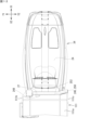
- FIG. 1 is a perspective view showing an embodiment of a work vehicle according to the present disclosure.
- FIG. 2 is a front view showing one embodiment of the work vehicle of the present disclosure.
- FIG. 3 is a rear view showing one embodiment of the work vehicle of the present disclosure.
- FIG. 4 is a right side view showing one embodiment of the work vehicle of the present disclosure.
- FIG. 5 is a left side view showing one embodiment of the work vehicle of the present disclosure.
- FIG. 6 is a plan view showing an embodiment of a work vehicle according to the present disclosure.
- FIG. 7 is a bottom view showing one embodiment of the work vehicle of the present disclosure.
- FIG. 8 is a perspective view showing a part of the work vehicle of the present disclosure in an exploded state.
- FIG. 9 is a left side view of the work vehicle with a portion removed.
- FIG. 10 is an explanatory diagram of the arrangement of hydrogen supply piping in a work vehicle.
- FIG. 11 is an explanatory diagram of the arrangement of hydrogen sensors and hinges around a fuel cell.
- FIG. 12 is a plan view showing the positional relationship between the hydrogen sensor and the bonnet and cover.
- FIG. 13 is a perspective view showing the positional relationship between the hydrogen sensor and the bonnet and cover.
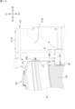
- FIG. 14 is a partially enlarged left side view showing the positional relationship between the hydrogen sensor and the bonnet and cover.
- FIG. 15 is an explanatory diagram of the hydrogen sensor, the bracket, and the hinge.
- FIG. 16 is an explanatory diagram of a state in which the bonnet is supported by the hinge.
- the purpose of this disclosure is to enable detection of hydrogen leaks under the hood of a work vehicle equipped with a fuel cell module and an electric motor.
- a hydrogen sensor can be easily installed around the fuel cell module inside the hood, making it possible to detect hydrogen leakage inside the hood of a work vehicle equipped with a fuel cell module and an electric motor.
- the work vehicle of this embodiment comprises a vehicle body, an electric motor and a fuel cell module mounted on the vehicle body, a bonnet covering the fuel cell module, hydrogen piping that supplies hydrogen to the inside of the bonnet, and a hydrogen sensor that detects hydrogen, the hydrogen sensor being fixed to the outer surface of the fuel cell module.
- a hydrogen sensor can be easily installed around the fuel cell module inside the hood. This makes it possible to detect hydrogen leakage inside the hood of a work vehicle equipped with a fuel cell module and an electric motor.
- the hydrogen sensor is fixed above the outer surface of the fuel cell module. This allows the hydrogen sensor to reliably detect hydrogen that moves upward in the event of a leak.
- the hydrogen sensor is fixed above the outer surface via a bracket that supports the hydrogen sensor. With a work vehicle configured in this way, the hydrogen sensor can be easily installed in the vicinity of the fuel cell module.
- the work vehicle according to this embodiment further includes a bonnet that covers the fuel cell module, and a hinge that supports the bonnet so that it can be opened and closed, and the hinge is preferably fixed to the bracket.
- the hinge is disposed above the fuel cell module.
- the hinge that supports the hood so that it can be opened and closed can be easily provided by utilizing the bracket that supports the hydrogen sensor.
- the fuel cell module further includes a connection port on the outer surface to which the hydrogen piping is connected, and the hydrogen sensor is fixed above the connection port on the outer surface.
- the hydrogen sensor can be easily installed in an area where hydrogen leakage is likely to occur. This makes it possible to reliably detect hydrogen leakage occurring inside the hood.
- FIG. 1 is a perspective view showing an embodiment of a work vehicle according to the present disclosure.
- Fig. 2 to Fig. 7 are a front view, a rear view, a side view (left side view), a side view (right side view), a plan view, and a bottom view of the work vehicle shown in Fig. 1.
- the work vehicle 10 of this embodiment is a vehicle that can be used for agricultural work, and the work vehicle 10 shown in Fig. 1 is a tractor.
- the work vehicle is not limited to a tractor.
- the work vehicle according to the present invention may be an agricultural machine, a construction machine, a utility vehicle, or the like other than a tractor.
- the directions of the work vehicle 10 of the present disclosure are defined below.
- the direction in which the work vehicle 10 moves forward is defined as “front”
- the direction in which the work vehicle 10 moves backward is defined as “back”
- the left side when facing forward is defined as “left”
- the right side when facing forward is defined as “right”.
- the left-right direction perpendicular to the front-to-rear direction is defined as the vehicle width direction.
- the direction perpendicular to both the front-to-rear direction and the vehicle width direction (left-to-right direction) is defined as the up-down direction.
- the up-down direction is also called the height direction.
- the work vehicle 10 shown in FIG. 1 has a vehicle body 11, a running device 12 that supports the vehicle body 11 so that it can run, a driver's seat 15, a cabin 16, a tank unit 21 having a tank 13 for storing fuel, and a drive device 14 that is powered by the fuel stored in the tank 13.
- the fuel is hydrogen
- the tank 13 is a hydrogen tank that stores hydrogen gas.
- the work vehicle 10 of this embodiment is a fuel cell vehicle (FCV), and runs on electricity generated by a fuel cell (fuel cell module) 24 using hydrogen and oxygen.
- FCV fuel cell vehicle
- the work vehicle 10 has a fuel cell 24, a battery unit 30, and an electric motor 31 as the drive device 14.
- the battery unit 30 has a battery 300 that stores the power generated by the fuel cell 24, and supplies the stored power to the motor 31.
- the work vehicle 10 has a piping (hydrogen piping) 22 for hydrogen gas, and a filling section 25 (see FIG. 3).
- the filling section 25 has a filling port (receptacle) 26 to which a filling nozzle of a hydrogen gas supply device (not shown) that is separate from the work vehicle 10 is connected. Hydrogen gas is supplied from the filling port 26 and supplied to the tank 13 through the piping 22 (rear piping 22r). The hydrogen gas in the tank 13 is supplied to the fuel cell 24 through the piping 22 (front piping 22f).
- the specific configurations of the filling section 25 and the piping 22 will be described later.
- the work vehicle 10 (see FIG. 1) has a mounting frame 17 and a support structure 37.
- the mounting frame 17 is a frame for mounting the tank unit 21 (tank 13) on the vehicle body 11.
- the support structure 37 is a component for supporting the battery unit 30 on the vehicle body 11.
- the work vehicle 10 (see FIG. 7) has an exhaust path 35.
- the exhaust path 35 exhausts water or water vapor generated by the operation of the fuel cell 24 to the outside.
- the vehicle body 11 has a chassis 41, a bonnet 34, a cover 111, and a fender 47 that covers the rear wheel 122 from above.
- the chassis 41 supports the traveling device 12, the drive device 14, and the cabin 16.
- Fig. 8 is an exploded perspective view of a part of the work vehicle 10 shown in Fig. 1.
- the chassis 41 is located at the center in the vehicle width direction and has a shape that is long in the vehicle front-rear direction.
- the chassis 41 has a front frame 32 that forms the front part of the chassis 41, and a gear case 33 that forms the rear part of the chassis 41.
- the front frame 32 is formed by combining metal frame materials and the like.
- the gear case 33 is formed by having a metal box body.
- the gear case 33 is connected to the rear part of the front frame 32, and the gear case 33 and the front frame 32 form the framework of the vehicle body 11.
- the front frame 32 mounts the motor 31.
- the gear case 33 has a power transmission mechanism 333 inside, such as a transmission, clutch, and differential gear.
- the power transmission mechanism 333 slows or speeds up the rotation of the output shaft of the motor 31, and outputs it to the running device 12 (one or both of the front wheels 121 and rear wheels 122).
- the power transmission mechanism 333 outputs a portion of the power of the motor 31 to the PTO shaft 334 (see FIG. 3).
- the PTO shaft 334 is an output shaft provided at the rear of the gear case 33.
- the work vehicle 10 has a coupling device 43 for coupling another device to the rear of the vehicle body 11.
- the PTO shaft 334 transmits the power of the motor 31 to the other device coupled to the coupling device 43.
- the other device is a work device (not shown), also called an implement.
- the work device is operated by the power of the motor 31.
- the work device is, for example, a tiller.
- FIG. 9 is a left side view of the work vehicle 10 with the bonnet 34, cover 111, and part of the tank case 211 of the tank unit 21 removed.
- a first radiator 48, a fuel cell 24, and a second radiator 49 are mounted on the chassis 41 in this order.
- the bonnet 34 and the cover 111 cover mounted components located toward the front of the vehicle body 11.
- the bonnet 34 covers the fuel cell 24 and the first radiator 48 from above and from both sides in the vehicle width direction.
- the cover 111 covers the second radiator 49 located behind the fuel cell 24 from above and from both sides in the vehicle width direction.
- An upper surface 48a of the first radiator 48 is lower than an upper surface 24a of the fuel cell 24.
- the upper surface 24a of the fuel cell 24 is lower than an upper surface 49a of the second radiator 49.
- the top surface 111a of the cover 111 is higher than the top surface 34a of the bonnet 34, but lower than the top end of the steering wheel 151 that is operated for steering by an operator sitting in the driver's seat 15.
- the top surface 34a of the bonnet 34 becomes lower toward the front. For this reason, the view of the operator sitting in the driver's seat 15 is less likely to be obstructed.
- the driver's seat 15 and the cabin 16 are provided on the chassis 41 at a rearward position (see FIG. 1).
- the cabin 16 has the driver's seat 15 therein.
- the cabin 16 has front pillars 162 located in front of the driver's seat 15, rear pillars 163 located behind the driver's seat 15, and a roof 164 located above the driver's seat 15.
- the front pillars 162 are provided on the left front and right front of the driver's seat 15.
- the rear pillars 163 are provided on the left rear and right rear of the driver's seat 15.
- the roof 164 is supported by the front pillars 162 and the rear pillars 163.
- the cabin 16 has a windshield 165 located in front of the driver's seat 15.
- the windshield 165 is provided between the left and right front pillars 162.
- the cabin 16 has openable and closable doors 166 on both sides in the vehicle width direction.
- the doors 166 are provided between the front pillars 162 and the rear pillars 163.
- a step 167 (see FIG. 5 ) is provided on one side (left side) of the cabin 16 in the vehicle body width direction.
- the step 167 is a member on which an operator who gets on and off the cabin 16 places his or her feet.
- a cover 111 and a bonnet 34 are provided in front of the cabin 16. As shown in Fig. 2 and Fig. 6, the dimensions of the cover 111 and the bonnet 34 in the vehicle width direction are each smaller than the dimension of the cabin 16 in the vehicle width direction. The dimension of the bonnet 34 in the vehicle width direction is smaller than the dimension of the cover 111 in the vehicle width direction.
- the work vehicle 10 of this embodiment has a cabin 16, but does not necessarily have to have the cabin 16.
- the work vehicle 10 may have a canopy or ropes instead of the cabin 16. If the work vehicle 10 does not have a cabin 16, the tank unit 21 is supported by the mounting frame 17 and positioned above the driver's seat 15.
- the traveling device 12 has front wheels 121 and rear wheels 122 (see FIG. 6 ).
- the front wheels 121 are provided on the left and right sides of the front part of the vehicle body 11.
- the rear wheels 122 are provided on the left and right sides of the rear part of the vehicle body 11.
- the maximum dimension in the vehicle width direction of the left and right rear wheels 122 is greater than the maximum dimension in the vehicle width direction of the left and right front wheels 121.
- the maximum dimension in the vehicle width direction of the left and right rear wheels 122 becomes the maximum vehicle width dimension of the work vehicle 10.
- One or both of the front wheels 121 and the rear wheels 122 rotate by the power of the motor 31.
- One or both of the front wheels 121 and the rear wheels 122 (drive wheels) that rotate by the power of the motor 31 may be crawlers (crawlers).
- the drive device 14 is configured to include the fuel cell 24 , the battery unit 30 , and the motor 31 .
- the fuel cell 24 is located on a chassis 41 near the front of the vehicle body 11 (see FIG. 9).
- the motor 31 is located behind the fuel cell 24 (see FIG. 8).
- the battery unit 30 is located toward the outer side in the vehicle width direction of the vehicle body 11 (see FIG. 1).
- the battery unit 30 is attached to the chassis 41 by a support structure 37.
- the fuel cell 24 generates electricity using hydrogen gas to obtain the power to rotate the motor 31.
- the fuel cell 24 (see Figure 9) has a battery casing 241 that is approximately rectangular and box-shaped, and a fuel cell stack 242 that is provided inside the battery casing 241.
- the fuel cell stack 242 has multiple battery cells. Each battery cell has a positive electrode and a negative electrode. Multiple single cells are stacked. The power generated by each battery cell is collected and output to the battery unit 30.
- the motor 31 has a rotating rotor and a stator with multiple coils.
- the output shaft of the motor 31 is connected to a power transmission mechanism 333 in the gear case 33 (see FIG. 8).
- the motor 31 is located behind the fuel cell 24 and below the second radiator 49.
- the tank unit 21 (see FIG. 9 ) has a tank 13 and a tank case 211 that houses the tank 13.
- the tank 13 is a substantially cylindrical high-pressure container.
- the tank 13 is made of fiber-reinforced resin reinforced with carbon fiber or glass fiber, or the like.
- three tanks 13 are fixed to the tank case 211 with the axial direction of their cylindrical portions parallel to the vehicle width direction.
- the number of tanks 13 is not limited to three.
- the tank case 211 is a box capable of housing one or more tanks 13.
- the tank case 211 has a box shape that covers the entire tank 13 it houses.
- the tank case 211 has an opening/closing door 213 (see FIG. 1) on one or both sides in the vehicle width direction, and opens in the vehicle width direction.
- the tank case 211 is installed above the roof 164, spaced apart from the roof 164 in the vertical direction.
- the tank case 211 is fixed to the upper frame portion 171 of the mounting frame 17.
- the tank case 211 is made of metal such as aluminum or steel, and protects the tank 13 from external thermal and physical influences.
- the tank 13 is positioned above the cabin 16 (driver's seat 15). This allows for a high degree of freedom in the placement of the fuel cell 24, charging section 25, motor 31, and battery unit 30 in the vehicle body 11.
- a conventional work vehicle with an internal combustion engine into a work vehicle 10 having a fuel cell 24 and motor 31 as in this embodiment, there is no need to significantly change the placement and configuration of each piece of equipment.
- the tank 13 is connected to the rear pipe 22r and the front pipe 22f via the valve unit 212 (see FIG. 9).
- the rear pipe 22r (see FIG. 3) is a gas inlet pipe that connects the hydrogen gas filling port 26 to the valve unit 212, and guides the hydrogen gas introduced into the filling port 26 to the tank 13.
- the front pipe 22f (see FIG. 2) is a gas outlet pipe that connects the fuel cell 24 to the valve unit 212, and guides the hydrogen gas stored in the tank 13 to the fuel cell 24.
- the tank 13 stores the hydrogen gas introduced into the filling port 26 from outside the vehicle and supplies it to the fuel cell 24.
- the valve unit 212 has an opening/closing valve, a pressure reducing valve, etc., and adjusts the hydrogen gas stored in the tank 13 to a predetermined flow rate and guides it to the fuel cell 24 through the front pipe 22f.
- the mounting frame 17 (see FIG. 1 ) is a frame structure for mounting the tank 13 on the vehicle body 11.
- the mounting frame 17 in this embodiment has an upper frame portion 171 that supports the tank 13, and a first front frame portion 172, a second front frame portion 175, and a rear frame portion 173 as frames for supporting the upper frame portion 171.
- a tank case 211 is attached to the upper frame portion 171.
- the upper frame portion 171 supports the tank 13 via the tank case 211.
- the specific configuration of the mounting frame 17 will be described later.
- the filling section 25 is provided on the rear frame section 173 (see FIG. 3).
- the filling section 25 has a filling port 26 to which a gas filling nozzle of a hydrogen gas supply device (not shown) installed outside the vehicle is connected when filling the tank 13 with hydrogen gas.
- the work vehicle 10 (see FIGS. 4 and 5) has a cooling system that uses a coolant to cool the fuel cell 24, the motor 31, the boost circuit 80, the inverter 81, the DC/DC converters 82, 83, etc.
- the work vehicle 10 has a first radiator 48 and a second radiator 49. As shown in FIG. 9, the first radiator 48 is located in front of the fuel cell 24, and the second radiator 49 is located behind the fuel cell 24.
- the first radiator 48 is a radiator for cooling devices other than the fuel cell 24.
- the second radiator 49 is a radiator for cooling the fuel cell 24.
- the first radiator 48 is connected, via a first cooling flow path (not shown) having a circulation pump, to electrical equipment (heat-generating components) that require cooling, such as the motor 31, the boost circuit 80, the inverter 81, and the DC/DC converters 82, 83.
- the first radiator 48 cools the coolant supplied through the first cooling flow path by heat exchange with the outside air.
- the second radiator 49 is connected to the fuel cell 24 via a second cooling passage (not shown) having a circulation pump.
- the second radiator 49 cools the coolant supplied through the second cooling passage by heat exchange with the outside air.
- the first radiator 48 has a first fan 481.
- the second radiator 49 has a second fan 491.
- the first fan 481 and the second fan 491 rotate to pass air through the first radiator 48 and the second radiator 49, promoting heat exchange with the coolant.
- the battery unit 30 accumulates power to be supplied to the motor 31.
- the battery unit 30 (see FIG. 9 ) has a battery (battery pack) 300 and a housing 307 that houses the battery 300.
- the battery 300 temporarily accumulates power generated by the fuel cell 24 and outputs the accumulated power to electrical devices such as the motor 31.
- the battery 300 is composed of multiple battery cells.
- the battery 300 is a charge-discharge type secondary battery such as a lithium ion battery or a lead storage battery.
- the work vehicle 10 has a junction box 75.
- the junction box 75 is an electric connection box for relaying and connecting and distributing the electric power output from the battery unit 30.
- the fuel cell 24 is connected to an inverter 81 (see FIG. 5 ) via a boost circuit.
- the battery unit 30 is connected to the inverter 81 through a junction box 75.
- the inverter 81 is electrically connected to the motor 31.
- the inverter 81 converts the DC power output from the boost circuit into three-phase AC power and outputs it to the motor 31.
- the work vehicle 10 has low-voltage electrical equipment that operates at a lower voltage than the motor 31.
- the low-voltage electrical equipment is supplied with power stepped down by a step-down circuit through a junction box 75.
- the low-voltage electrical equipment of the work vehicle 10 is the battery unit 30, radiators 48, 49, and air conditioning device 74.
- the work vehicle 10 has a first DC/DC converter 82 and a second DC/DC converter 83 as the step-down circuit.
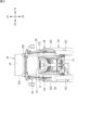
- FIG. 10 is an explanatory diagram of the arrangement of hydrogen supply piping in a work vehicle.
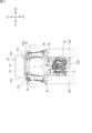
- FIG. 11 is an explanatory diagram of the arrangement of a hydrogen sensor and a hinge around a fuel cell.
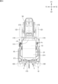
- FIG. 12 is a plan view showing the positional relationship between the hydrogen sensor, the bonnet, and the cover.
- FIG. 13 is a perspective view showing the positional relationship between the hydrogen sensor, the bonnet, and the cover.
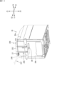
- FIG. 14 is a partially enlarged left side view showing the positional relationship between the hydrogen sensor, the bonnet, and the cover. As shown in FIG. 10 and FIG.
- the work vehicle 10 of the present disclosure includes a rear pipe 22r that introduces hydrogen from the filling port 26 of the filling section 25 to the tank 13 via the valve unit 212, and a front pipe 22f that extends from the tank 13 to the fuel cell 24 via the valve unit 212.
- the fuel cell 24 includes a connection port 28 to which the front pipe 22f is connected.
- the connection port 28 is provided on the rear surface 24b, which is the outer surface on the rear side of the fuel cell 24.
- the work vehicle 10 is equipped with a hydrogen sensor 27 that detects leakage of hydrogen supplied to the fuel cell 24 through the front pipe 22f.
- the hydrogen sensor 27 is fixed above the connection port 28 on the rear surface 24b of the fuel cell 24.
- the hydrogen sensor 27 is provided above the connection port 28, where hydrogen can be easily detected in the event of a hydrogen leak from the connection port 28.
- the hydrogen sensor 27 may be fixed to the outer surface of the fuel cell 24 other than the rear surface 24b.
- the work vehicle 10 has a cover 111 that covers the fuel cell 24 and the rear of the bonnet 34, and the second radiator 49 (see Figure 5).
- the cover 111 has an upper surface 111a, a left side surface 111b, and a right side surface 111c.
- the upper surface 111a is located above the bonnet 34.
- the left side surface 111b is located on the left side of the bonnet 34.
- the right side surface 111c is located on the right side of the bonnet 34.
- Part of the left and right sides of the fuel cell 24 are covered by side covers 112 made of a mesh body.
- the upper surface 111a of the cover 111 is positioned in a plan view so as to cover the connection port 28 and the upper part of the hydrogen sensor 27.
- the hydrogen sensor 27 is surrounded by the top surface 111a, left side surface 111b, and right side surface 111c of the cover 111. Also, as shown in Fig. 14, a part of the hydrogen sensor 27 is disposed between the rear end of the bonnet 34 and the cover 111 (in the space) in a side view. The hydrogen sensor 27 may be surrounded by the top surface 111a, left side surface 111b, and right side surface 111c of the cover 111, or it may be surrounded by the bonnet 34. By arranging hydrogen sensor 27, work vehicle 10 is able to detect hydrogen leaking from connection port 28. Furthermore, in work vehicle 10, hydrogen sensor 27 is arranged at the upper part of the space surrounded by cover 111, so that hydrogen flowing upward from within cover 111 can be reliably detected.
- the hydrogen sensor 27 is fixed to the fuel cell 24. With a work vehicle 10 configured in this way, the hydrogen sensor 27 can be easily installed in the vicinity of the fuel cell 24. This makes it possible to save space inside the hood 34 of a work vehicle 10 equipped with a fuel cell 24 and a motor 31.
- FIG. 15 is an explanatory diagram of the hydrogen sensor, bracket, and hinge.
- the work vehicle 10 of the present disclosure is equipped with a bracket 245.
- the bracket 245 is made of steel and is fixed to the rear surface 24b of the fuel cell 24.
- the hydrogen sensor 27 is fixed to the rear surface 24b of the fuel cell 24 via the bracket 245.
- the bracket 245 is composed of two first members 245a extending in the vertical direction and one second member 245b extending in the horizontal direction.
- the bracket 245 is composed integrally by connecting the upper ends of the two first members 245a with the second member 245b.
- the bracket 245 is fixed to the fuel cell 24 by inserting bolts 246 into a plurality of bolt holes provided in the first member 245a and screwing the bolts 246 into bolt holes (not shown) formed in the rear surface 24b of the fuel cell 24.
- the bracket 245 is fixed to the fuel cell 24 using bolt holes (not shown) that are originally provided in the fuel cell 24. Therefore, there is no need to change the shape and structure of the frame and casing of the fuel cell 24.
- the second member 245b further includes an extension 248 that extends rearward from its left end.
- the extension 248 is a portion that fixes the hydrogen sensor 27 to the bracket 245.
- the hydrogen sensor 27 is fixed to the extension 248 by a screw member (bolt and nut) 29.
- the second member 245b is used as a portion that fixes a hinge (hinge 250, described later) for supporting the bonnet 34 (see FIG. 1) to the bracket 245.
- the hydrogen sensor 27 can be easily provided on the outer surface (rear surface 24b) of the fuel cell 24 without changing the structure of the fuel cell 24.
- FIG. 16 is an explanatory diagram of the state in which the bonnet is supported by the hinge.
- the work vehicle 10 of the present disclosure includes a hinge 250 attached to the upper end of the bracket 245.
- the hinge 250 is a member that supports the bonnet 34 of the work vehicle 10, and includes a hinge body 251 and a shaft 252.
- the hinge 250 is fixed to the upper side of the bracket 245 by fastening the hinge body 251 to the second member 245b with a bolt 253 (and a nut).
- the shaft 252 is held by the hinge body 251 in a position in which the axial direction faces the left-right direction.
- the hinge 250 is disposed above the bonnet 34. As shown in FIG.
- the bonnet 34 is supported by the shaft 252 so as to be rotatable around the axis of the shaft 252.
- the upper bonnet 34 indicated by the two-dot chain line indicates the open state of the bonnet 34
- the lower bonnet 34 indicated by the two-dot chain line indicates the closed state of the bonnet 34.
- the work vehicle 10 of the present disclosure supports the hood 34 so that it can be opened and closed by a hinge 250 attached to the bracket 245.
- the hood 34 is rotatably supported by the fuel cell 24 via the hinge 250 and the bracket 245.
- a work vehicle 10 configured in this manner does not need to provide a separate dedicated frame inside the bonnet 34 to support the bonnet 34. This allows the work vehicle 1 to omit the dedicated frame, thereby saving space around the fuel cell 24. This allows the work vehicle 10 of the present disclosure to suppress an increase in overall length. And, with this configuration, the work vehicle 10 of the present disclosure can maintain maneuverability and minimum turning radius that are almost the same as those of conventional (engine-equipped) work vehicles, even though it is a work vehicle 10 equipped with a fuel cell 24.
Landscapes
- Engineering & Computer Science (AREA)
- Life Sciences & Earth Sciences (AREA)
- Sustainable Energy (AREA)
- Sustainable Development (AREA)
- Mechanical Engineering (AREA)
- Chemical & Material Sciences (AREA)
- Transportation (AREA)
- Power Engineering (AREA)
- Manufacturing & Machinery (AREA)
- Chemical Kinetics & Catalysis (AREA)
- Electrochemistry (AREA)
- General Chemical & Material Sciences (AREA)
- Combustion & Propulsion (AREA)
- Soil Sciences (AREA)
- Environmental Sciences (AREA)
- Arrangement Or Mounting Of Propulsion Units For Vehicles (AREA)
- Cooling, Air Intake And Gas Exhaust, And Fuel Tank Arrangements In Propulsion Units (AREA)
- Fuel Cell (AREA)
Priority Applications (3)
| Application Number | Priority Date | Filing Date | Title |
|---|---|---|---|
| EP24831403.1A EP4737168A1 (en) | 2023-06-30 | 2024-05-01 | Work vehicle |
| JP2025529474A JPWO2025004530A1 (https=) | 2023-06-30 | 2024-05-01 | |
| US19/391,089 US20260070424A1 (en) | 2023-06-30 | 2025-11-17 | Work vehicle |
Applications Claiming Priority (2)
| Application Number | Priority Date | Filing Date | Title |
|---|---|---|---|
| JP2023-107684 | 2023-06-30 | ||
| JP2023107684 | 2023-06-30 |
Related Child Applications (1)
| Application Number | Title | Priority Date | Filing Date |
|---|---|---|---|
| US19/391,089 Continuation US20260070424A1 (en) | 2023-06-30 | 2025-11-17 | Work vehicle |
Publications (1)
| Publication Number | Publication Date |
|---|---|
| WO2025004530A1 true WO2025004530A1 (ja) | 2025-01-02 |
Family
ID=93938212
Family Applications (1)
| Application Number | Title | Priority Date | Filing Date |
|---|---|---|---|
| PCT/JP2024/016832 Ceased WO2025004530A1 (ja) | 2023-06-30 | 2024-05-01 | 作業車両 |
Country Status (4)
| Country | Link |
|---|---|
| US (1) | US20260070424A1 (https=) |
| EP (1) | EP4737168A1 (https=) |
| JP (1) | JPWO2025004530A1 (https=) |
| WO (1) | WO2025004530A1 (https=) |
Citations (5)
| Publication number | Priority date | Publication date | Assignee | Title |
|---|---|---|---|---|
| JP2002316669A (ja) * | 2001-04-24 | 2002-10-29 | Kanzaki Kokyukoki Mfg Co Ltd | トラクタのボンネット構造 |
| JP2009043427A (ja) * | 2007-08-06 | 2009-02-26 | Toyota Industries Corp | 燃料電池型産業車両の異常検知装置 |
| CN210149159U (zh) * | 2019-06-04 | 2020-03-17 | 武汉海亿新能源科技有限公司 | 一种基于燃料电池的农用拖拉机 |
| JP2022060655A (ja) | 2020-10-05 | 2022-04-15 | ヤマハ株式会社 | 回路基板および検出システム |
| JP2022154990A (ja) * | 2021-03-30 | 2022-10-13 | 本田技研工業株式会社 | センサ及びセンサシステム |
-
2024
- 2024-05-01 WO PCT/JP2024/016832 patent/WO2025004530A1/ja not_active Ceased
- 2024-05-01 JP JP2025529474A patent/JPWO2025004530A1/ja active Pending
- 2024-05-01 EP EP24831403.1A patent/EP4737168A1/en active Pending
-
2025
- 2025-11-17 US US19/391,089 patent/US20260070424A1/en active Pending
Patent Citations (5)
| Publication number | Priority date | Publication date | Assignee | Title |
|---|---|---|---|---|
| JP2002316669A (ja) * | 2001-04-24 | 2002-10-29 | Kanzaki Kokyukoki Mfg Co Ltd | トラクタのボンネット構造 |
| JP2009043427A (ja) * | 2007-08-06 | 2009-02-26 | Toyota Industries Corp | 燃料電池型産業車両の異常検知装置 |
| CN210149159U (zh) * | 2019-06-04 | 2020-03-17 | 武汉海亿新能源科技有限公司 | 一种基于燃料电池的农用拖拉机 |
| JP2022060655A (ja) | 2020-10-05 | 2022-04-15 | ヤマハ株式会社 | 回路基板および検出システム |
| JP2022154990A (ja) * | 2021-03-30 | 2022-10-13 | 本田技研工業株式会社 | センサ及びセンサシステム |
Also Published As
| Publication number | Publication date |
|---|---|
| JPWO2025004530A1 (https=) | 2025-01-02 |
| US20260070424A1 (en) | 2026-03-12 |
| EP4737168A1 (en) | 2026-05-06 |
Similar Documents
| Publication | Publication Date | Title |
|---|---|---|
| US11273717B2 (en) | Open cabin vehicle | |
| JP6331838B2 (ja) | 燃料電池二輪車 | |
| JP2025006700A (ja) | 作業車両 | |
| WO2025004530A1 (ja) | 作業車両 | |
| JP2025102031A (ja) | 作業車両 | |
| WO2025004529A1 (ja) | 作業車両 | |
| JP2025006682A (ja) | 作業車両 | |
| WO2025004527A1 (ja) | 作業車両 | |
| WO2025004682A1 (ja) | 作業車両 | |
| WO2025004670A1 (ja) | 作業車両 | |
| JP2024092286A (ja) | 燃料電池車両 | |
| WO2025004676A1 (ja) | 作業車両 | |
| WO2025004673A1 (ja) | 作業車両 | |
| WO2025142002A1 (ja) | 作業機械、及び作業車両 | |
| JP7810192B2 (ja) | 電動車 | |
| JP2025009259A (ja) | 作業車両 | |
| WO2024143321A1 (ja) | 作業車両 | |
| JP7797372B2 (ja) | 作業車両 | |
| WO2025141996A1 (ja) | 作業車両 | |
| JP2024095105A (ja) | 作業車両 | |
| WO2025004576A1 (ja) | 作業車両 | |
| WO2025004578A1 (ja) | 作業車両 | |
| WO2025004575A1 (ja) | 作業車両 | |
| WO2025004577A1 (ja) | 作業車両 | |
| JP2025102043A (ja) | 作業車両 |
Legal Events
| Date | Code | Title | Description |
|---|---|---|---|
| 121 | Ep: the epo has been informed by wipo that ep was designated in this application |
Ref document number: 24831403 Country of ref document: EP Kind code of ref document: A1 |
|
| ENP | Entry into the national phase |
Ref document number: 2025529474 Country of ref document: JP Kind code of ref document: A |
|
| WWE | Wipo information: entry into national phase |
Ref document number: 2025529474 Country of ref document: JP |
|
| WWE | Wipo information: entry into national phase |
Ref document number: 2024831403 Country of ref document: EP |
|
| NENP | Non-entry into the national phase |
Ref country code: DE |
|
| ENP | Entry into the national phase |
Ref document number: 2024831403 Country of ref document: EP Effective date: 20260130 |
|
| ENP | Entry into the national phase |
Ref document number: 2024831403 Country of ref document: EP Effective date: 20260130 |