WO2025004281A1 - 電子制御装置、およびその製造方法 - Google Patents
電子制御装置、およびその製造方法 Download PDFInfo
- Publication number
- WO2025004281A1 WO2025004281A1 PCT/JP2023/024243 JP2023024243W WO2025004281A1 WO 2025004281 A1 WO2025004281 A1 WO 2025004281A1 JP 2023024243 W JP2023024243 W JP 2023024243W WO 2025004281 A1 WO2025004281 A1 WO 2025004281A1
- Authority
- WO
- WIPO (PCT)
- Prior art keywords
- bracket
- electronic control
- control device
- mold
- housing
- Prior art date
- Legal status (The legal status is an assumption and is not a legal conclusion. Google has not performed a legal analysis and makes no representation as to the accuracy of the status listed.)
- Ceased
Links
Images


Classifications
-
- H—ELECTRICITY
- H05—ELECTRIC TECHNIQUES NOT OTHERWISE PROVIDED FOR
- H05K—PRINTED CIRCUITS; CASINGS OR CONSTRUCTIONAL DETAILS OF ELECTRIC APPARATUS; MANUFACTURE OF ASSEMBLAGES OF ELECTRICAL COMPONENTS
- H05K5/00—Casings, cabinets or drawers for electric apparatus
- H05K5/04—Metal casings
Definitions
- the housing of the electronic control device disclosed in Patent Document 1 exposes part of the connector to the outside through a connector opening formed when the upper first case and the lower second case are assembled, while the remaining part of the connector and the circuit board are housed in the internal space.
- the first case and the second case are die-cast aluminum products.
- a number of heat dissipation fins are integrally formed on the top surface of the first case.
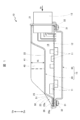
- the electronic control device 10 includes a circuit board 12 on which electronic components 11 are mounted, a connector 13 for external connection mounted on the circuit board 12, and a housing 15 having an internal space 14 for housing the circuit board 12.
- the housing 15 is composed of a first case 20 that is open on the bottom side and a second case 30 that is open on the top side.
- the upper first case 20 and the lower second case 30 are stacked together and assembled with screws 31 to form an internal space 14 in the housing 15.
- the first case 20 is a die-cast product made of a light metal with excellent thermal conductivity, such as aluminum (including aluminum alloys).
- the second case 30 is a press-formed product made of a metal plate.
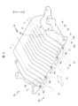
- the first case 20 when viewed from the connector opening 21 side (viewed from the line of sight of the arrow Ar), the first case 20 has a surface 22 (top surface 22) opposite the second case 30, a back surface 23 opposite the connector opening 21, and left and right side surfaces 24 (only one side is shown).
- the top surface 22 is a flat plane.
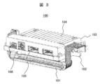
- FIG. 3 is a perspective view of the electronic control device 100 according to the present invention.
- the electronic control device 100 is used by screwing a body bracket 101 for mounting to the vehicle side to a bracket 102.
- the body side bracket 101 is fixed to the vehicle side to which it is to be mounted by screwing.
- the body side bracket 101 can take various shapes depending on the mounting structure to the vehicle side.
- 102 is an upper case
- 104 is a heat dissipation fin provided on the upper case 103
- 105 is a connector
- 108 is a lower case to which the circuit board is fixed.
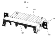
- FIG. 4 is a perspective view of the upper case 103 of the electronic control device in FIG. 3.
- the screw mounting holes 105 of the bracket 102 are visible. Screws are inserted into the screw mounting holes to secure the body side bracket 101.
- the connector opening 107 is where the connector fits in when the upper case 103 is combined with the lower case 108.
- the upper case 103 is manufactured by a die-casting method.
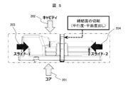
- the manufacturing method will be explained using Figure 5.
- a fixed mold (core) 201 and a movable mold (cavity) 202 are pressed so as to sandwich the upper case from above and below, and at the same time, a pair of slide molds (core molds) 203 and 204 are pressed in a direction perpendicular to the connector opening, and the mold is divided and cast.
- the mounting surface of the bracket 102 can be changed in a 360-degree direction relative to the connector opening surface by changing the angle of the pressing surface of the slide mold.
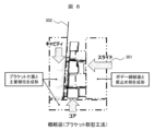
- a mold can be constructed in which a slide mold 301 is used only on the side where the body side bracket 101 is fastened to achieve precision, and the side where the body side bracket 101 is not fastened has a taper (punch taper) 302 that allows the cavity mold to be removed.
- a taper punch taper
- Figure 7(a) is a front view of bracket 102
- Figure 7(b) shows the A-A cross section of Figure 7(a). As shown in Figure 7(b), it is effective to perform cutting so that the surface (abutment surface) with which body bracket 101 comes into contact is parallel to the opposing bolt (screw) fastening surface.
- the bracket can also be L-shaped as shown in Figures 9(a) to (d). This structure can improve the ease of assembly with the vehicle bracket.
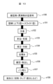
- FIG. 10 shows a manufacturing flow of the upper case 103 of the present invention.
- a release agent and a lubricant are applied to the die-casting die (step s100).
- the core die which is a fixed die
- the cavity die which is a movable die
- the slide die for making the bracket in this figure, there is only one slide die
- Molten aluminum is poured into the aligned dies (pouring: step s102).
- the cavity die and the slide die, which are movable dies, are moved and injected to fill the molten metal (step s103).
- the molten metal is cooled while maintaining the pressure applied to the die until it solidifies (step s105). After cooling is completed, the die is opened (step s105).
- the die-cast casting is removed from the die (mold release/removal step s106).
- the burrs on the removed casting are removed using a grinder or the like (deburring step s107).
- Post-processing steps such as cutting, tapping, and facing (s108).
- the upper case of the present invention is manufactured through such a process.
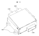
- Comparative Example A conventional electronic control device is shown in Fig. 11.
- the connector openings are 2100, 3100, and 3200.
- the bracket is 600.
- the upper case of a conventional electronic control device was generally manufactured using only two molds, a cavity mold and a core mold, with an emphasis on ease of manufacture. Therefore, the bracket 600 had a fastening surface parallel to the circuit board (i.e., perpendicular to the connector opening surface).
Landscapes
- Engineering & Computer Science (AREA)
- Microelectronics & Electronic Packaging (AREA)
- Casings For Electric Apparatus (AREA)
Abstract
Description
本発明の実施の形態を添付図に基づいて以下に説明する。なお、添付図に示した形態は本発明の一例であり、本発明は当該形態に限定されない。図中Upは上、Dnは下を示している。
まず、離型剤、潤滑剤をダイカスト金型に塗布する(ステップs100)。次に固定金型であるコア金型、可動金型であるキャビティ金型、ブラケットを作製するためのスライド金型(この図の場合はスライド金型は1つ)を注湯位置に合わせる(型締:ステップs101)。合わせた金型に溶けたアルミニウムを注ぐ(注湯:ステップs102)。移動金型であるキャビティ、スライド金型を移動して射出、溶湯の充填を行う(ステップs103)。溶けた金属が固まるまで金型にかけた圧力を保持したまま冷却する(ステップs105)。冷却終了後、金型を開く(ステップs105)。ダイキャストされた鋳物を金型から外す(離型・取り出しステップs106)。取り出した鋳物のバリをグラインダー等を用いてバリを取り除く(バリ取りステップs107)。
切削、タップ、面出しなどの後工程ステップ(s108)。
このような工程で本発明の上ケースを製造する。
<比較例>
図11に従来の電子制御装置を示す。コネクタ開口部は2100、3100、3200。ブラケットは600である。従来の電子制御装置の上ケースは製造の容易性を重視しキャビティ金型とコア金型の2つの金型のみで製造することが一般的であった。そのため、ブラケット600は回路基板に平行(すなわち、コネクタ開口面に垂直)に締結面があった。
Claims (5)
- 少なくとも所定位置に取り付けるためのブラケットと、コネクタ開口部と、を有する筐体を備えた電子制御装置の製造方法において、
前記筐体は、前記コネクタ開口部と概ね垂直な方向に押圧するキャビティ金型及び該キャビティ金型の押圧を受けるコア金型、及び該押圧方向と概ね直交する方向にスライドするスライド金型と、を用いてダイカスト法で製造され、
前記ブラケットの取付面は、該スライド金型の押圧面に水平な面を持ち、かつ該筐体と一体で製造され、
更に、前記スライド金型は1つのみ使用し、該スライド金型で押圧されない前記ブラケットの取付面は前記キャビティ金型の抜きテーパー面を持ち、かつ前記抜きテーパー面は離型後に前記スライド金型の押圧面に水平な面と平行な面となるよう切削加工することを特徴とする電子制御装置の製造方法。 - 請求項1記載の電子制御装置の製造方法において、
前記切削加工は、前記ブラケットを固定するためのネジの締結面の近傍のみを切削することを特徴とする電子制御装置の製造方法。 - 請求項1記載の電子制御装置の製造方法において、
前記ブラケットは前記スライド金型の押圧面に水平な面を持つ取付け面に対し概ね直交する第二の取付面を有することを特徴とする電子制御装置の製造方法。 - 少なくとも所定位置に取り付けるためのブラケットと、コネクタ開口部と、を有する筐体を備えた電子制御装置であって、
前記筐体は、前記コネクタ開口部と概ね平行な面に前記ブラケットの取付面を有し、かつ該筐体と一体となっており、
更に、前記ブラケットの取付面のうちの一方はダイカスト金型の抜きテーパー面を持ち、
前記ダイカスト金型の抜きテーパー面は、少なくともその一部が前記ブラケットの他方の取付け面に平行な面となるよう加工されていることを特徴とする電子制御装置。 - 請求項4記載の電子制御装置において、
前記ブラケットの他方の取付け面に平行な面となるよう加工されている面は、前記ブラケットを固定するためのネジの締結面の近傍のみであることを特徴とする電子制御装置。
Priority Applications (3)
| Application Number | Priority Date | Filing Date | Title |
|---|---|---|---|
| JP2025529134A JP7870409B2 (ja) | 2023-06-29 | 2023-06-29 | 電子制御装置、およびその製造方法 |
| CN202380094367.1A CN120712903A (zh) | 2023-06-29 | 2023-06-29 | 电子控制装置及其制造方法 |
| PCT/JP2023/024243 WO2025004281A1 (ja) | 2023-06-29 | 2023-06-29 | 電子制御装置、およびその製造方法 |
Applications Claiming Priority (1)
| Application Number | Priority Date | Filing Date | Title |
|---|---|---|---|
| PCT/JP2023/024243 WO2025004281A1 (ja) | 2023-06-29 | 2023-06-29 | 電子制御装置、およびその製造方法 |
Publications (1)
| Publication Number | Publication Date |
|---|---|
| WO2025004281A1 true WO2025004281A1 (ja) | 2025-01-02 |
Family
ID=93938233
Family Applications (1)
| Application Number | Title | Priority Date | Filing Date |
|---|---|---|---|
| PCT/JP2023/024243 Ceased WO2025004281A1 (ja) | 2023-06-29 | 2023-06-29 | 電子制御装置、およびその製造方法 |
Country Status (3)
| Country | Link |
|---|---|
| JP (1) | JP7870409B2 (ja) |
| CN (1) | CN120712903A (ja) |
| WO (1) | WO2025004281A1 (ja) |
Citations (2)
| Publication number | Priority date | Publication date | Assignee | Title |
|---|---|---|---|---|
| JP2007002714A (ja) * | 2005-06-23 | 2007-01-11 | Honda Motor Co Ltd | 傾斜シリンダ付き空冷エンジン |
| JP2022171101A (ja) * | 2021-04-30 | 2022-11-11 | 株式会社デンソーテン | 制御装置 |
-
2023
- 2023-06-29 WO PCT/JP2023/024243 patent/WO2025004281A1/ja not_active Ceased
- 2023-06-29 JP JP2025529134A patent/JP7870409B2/ja active Active
- 2023-06-29 CN CN202380094367.1A patent/CN120712903A/zh active Pending
Patent Citations (2)
| Publication number | Priority date | Publication date | Assignee | Title |
|---|---|---|---|---|
| JP2007002714A (ja) * | 2005-06-23 | 2007-01-11 | Honda Motor Co Ltd | 傾斜シリンダ付き空冷エンジン |
| JP2022171101A (ja) * | 2021-04-30 | 2022-11-11 | 株式会社デンソーテン | 制御装置 |
Also Published As
| Publication number | Publication date |
|---|---|
| CN120712903A (zh) | 2025-09-26 |
| JP7870409B2 (ja) | 2026-06-04 |
| JPWO2025004281A1 (ja) | 2025-01-02 |
Similar Documents
| Publication | Publication Date | Title |
|---|---|---|
| JP3021296B2 (ja) | 電子機器用箱体、その製造方法およびその使用方法 | |
| US20020011326A1 (en) | Air rectification blades | |
| EP2327286B1 (de) | Schaltungsgehäuse mit wärmekopplungselement | |
| CN113382595B (zh) | 具有挤压冷却腔的辅助冷却式电子组件 | |
| US20040257757A1 (en) | Housing with device for electronic control units, in particular in motor vehicles | |
| TWI535508B (zh) | 金屬件及金屬件成型方法 | |
| JP4013378B2 (ja) | 電子制御機器及びその治具構造 | |
| JPWO2011155247A1 (ja) | ヒートシンクおよびその製造方法 | |
| JPH0573269B2 (ja) | ||
| US6460823B1 (en) | Movable mounting lug for a compressor | |
| WO2025224148A1 (en) | Housing part for a control device housing with flat contacting locations on cooling fins, housing for a control device, control device and method for producing a housing part | |
| CN120712903A (zh) | 电子控制装置及其制造方法 | |
| JP3325705B2 (ja) | 電子機器の放熱装置 | |
| US5832983A (en) | Casting mold for moldings | |
| JP7489891B2 (ja) | 樹脂筐体および電子制御装置 | |
| JPS62286657A (ja) | ヒ−トシンクの製造方法 | |
| CN218072019U (zh) | 一种用于汽车事件记录系统的铝型材外壳结构 | |
| JP2009508328A (ja) | 電子機器ケーシングのためのヒートシンク | |
| CN114698341A (zh) | 双基板散热器及双基板散热器制造方法 | |
| JP2017174992A (ja) | 電子制御ユニット | |
| JP4228820B2 (ja) | 電子機器の筐体構造 | |
| CN217116741U (zh) | 车用电子装置 | |
| JP2023180096A (ja) | 回路基板の収納構造及び回路基板モジュール | |
| JP3760065B2 (ja) | 冷却ファン装着型ヒートシンクの製造方法 | |
| JP4342132B2 (ja) | 制御機器用ヒートシンクおよび制御機器 |
Legal Events
| Date | Code | Title | Description |
|---|---|---|---|
| 121 | Ep: the epo has been informed by wipo that ep was designated in this application |
Ref document number: 23943674 Country of ref document: EP Kind code of ref document: A1 |
|
| ENP | Entry into the national phase |
Ref document number: 2025529134 Country of ref document: JP Kind code of ref document: A |
|
| WWE | Wipo information: entry into national phase |
Ref document number: 2025529134 Country of ref document: JP |
|
| NENP | Non-entry into the national phase |
Ref country code: DE |
|
| 122 | Ep: pct application non-entry in european phase |
Ref document number: 23943674 Country of ref document: EP Kind code of ref document: A1 |