WO2025004245A1 - 通信装置、通信システム及び給電方法 - Google Patents
通信装置、通信システム及び給電方法 Download PDFInfo
- Publication number
- WO2025004245A1 WO2025004245A1 PCT/JP2023/024066 JP2023024066W WO2025004245A1 WO 2025004245 A1 WO2025004245 A1 WO 2025004245A1 JP 2023024066 W JP2023024066 W JP 2023024066W WO 2025004245 A1 WO2025004245 A1 WO 2025004245A1
- Authority
- WO
- WIPO (PCT)
- Prior art keywords
- power supply
- power
- unit
- units
- light
- Prior art date
- Legal status (The legal status is an assumption and is not a legal conclusion. Google has not performed a legal analysis and makes no representation as to the accuracy of the status listed.)
- Ceased
Links
Images



Classifications
-
- H—ELECTRICITY
- H04—ELECTRIC COMMUNICATION TECHNIQUE
- H04B—TRANSMISSION
- H04B10/00—Transmission systems employing electromagnetic waves other than radio-waves, e.g. infrared, visible or ultraviolet light, or employing corpuscular radiation, e.g. quantum communication
- H04B10/80—Optical aspects relating to the use of optical transmission for specific applications, not provided for in groups H04B10/03 - H04B10/70, e.g. optical power feeding or optical transmission through water
Definitions
- the present invention relates to a communication device, a communication system, and a power supply method.
- FIG. 5 is a configuration diagram of a conventional communication system 100 powered by optical power supply.
- the communication system 100 comprises a power supply light source 110, an optical line terminal (OLT) 120, and an optical network unit (ONU) 130.
- the ONU 130 is connected to both the power supply light source 110 and the OLT 120 by optical fibers.
- the ONU 130 transmits and receives optical signals to and from the OLT 120 to perform data communication, and is powered by optical power supply from the power supply light source 110.
- the power supply light source 110 includes a laser 111.
- the laser 111 outputs light of a certain wavelength as power supply light.
- the OLT 120 includes a communication function unit 121 and a transmission/reception unit 122.
- the communication function unit 121 generates a data signal to be transmitted to the ONU 130, and receives a data signal received from the ONU 130.
- the transmission/reception unit 122 converts the data signal generated by the communication function unit 121 and addressed to the ONU 130 from an electrical signal to an optical signal, and outputs the converted signal to an optical fiber.
- the transmission/reception unit 122 receives an optical signal output from the ONU 130 and transmitted through the optical fiber, converts the received optical signal into an electrical data signal, and outputs the converted signal to the communication function unit 121.
- the ONU 130 includes a photoelectric conversion unit 131, a sensor 132, a transmission/reception unit 133, and a communication function unit 134.
- the photoelectric conversion unit 131 includes a light receiving unit 135 and a power supply unit 136.
- the power supply unit 136 includes a voltage conversion unit 137, a secondary battery 138, a voltage conversion unit 139, a voltage conversion unit 140, a voltage conversion unit 141, and a voltage conversion unit 142.
- the light receiving unit 135 converts the power supply light output from the power supply light source 110 into electricity.
- the voltage conversion unit 137 converts the voltage of the electricity.
- the secondary battery 138 stores the electricity after the voltage conversion by the voltage conversion unit 137.
- the voltage conversion unit 139 converts the voltage of the electricity stored in the secondary battery 138 into a common voltage.
- the voltage conversion unit 140 supplies power to the transmission/reception unit 133. Therefore, the voltage conversion unit 140 converts the power after the voltage conversion by the voltage conversion unit 137 into power C suitable for use by the transmission/reception unit 133, and then supplies it to the transmission/reception unit 133.
- the voltage conversion unit 141 supplies power to the communication function unit 134. Therefore, the voltage conversion unit 141 converts the power after the voltage conversion by the voltage conversion unit 137 into power B suitable for use by the communication function unit 134, and then supplies it to the communication function unit 134.
- the voltage conversion unit 142 supplies power to the sensor 132. Therefore, the voltage conversion unit 142 converts the power after the voltage conversion by the voltage conversion unit 137 into power A suitable for use by the sensor 132, and then supplies it to the sensor 132.
- the ONU 130 which is driven by optical power supply from the power supply light source 110, needs to efficiently secure power.
- the conventional ONU 130 needs to first convert the power to a common voltage and then convert the voltage again. This causes a large energy loss due to the voltage conversion section, making it difficult to efficiently secure power.
- the present invention aims to provide technology that can reduce energy loss and efficiently secure power.
- One aspect of the present invention is a communication device that includes a plurality of light receiving units that are connected to different power supply light sources among a plurality of power supply light sources that output power supply light used for power supply and convert the power supply light output from the connected power supply light sources into electric power, and a plurality of power supply units that supply the electric power converted by each of the plurality of light receiving units to a power supply unit that operates by power supply.
- One aspect of the present invention is a communication system that includes a plurality of power supply light sources that output power supply light used for power supply, and a communication device, the communication device including a plurality of light receiving units that connect to different power supply light sources among the plurality of power supply light sources and convert the power supply light output from the connected power supply light sources into electric power, and a plurality of power supply units that supply the electric power converted by each of the plurality of light receiving units to a power supply unit that operates by power supply.
- One aspect of the present invention is a power supply method in which a plurality of light receiving units, each connected to a different one of a plurality of power supply light sources that output power supply light used for power supply, convert the power supply light into electric power, and supply the converted electric power from a plurality of power supply units to a power-receiving unit that operates by power supply.
- This invention makes it possible to reduce energy loss and ensure efficient power generation.
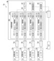
- FIG. 1 is a configuration diagram of a communication system according to a first embodiment.
- FIG. 2 is a sequence diagram for explaining a processing flow of the communication system in the first embodiment.
- FIG. 11 is a diagram illustrating an example of the configuration of an ONU in a second embodiment.
- FIG. 13 is a configuration diagram of a communication system according to a third embodiment.
- FIG. 1 is a configuration diagram of a conventional communication system driven by optical power supply.
- Fig. 1 is a configuration diagram of a communication system 1 in a first embodiment.
- the communication system 1 includes a plurality of power supply light sources 2, an OLT 3, and an ONU 4.
- the power supply light sources 2 and the ONU 4 are connected by an optical fiber 5, and the OLT 3 and the ONU 4 are connected by an optical fiber 6.
- the ONU 4 is an example of a communication device, and the optical fibers 5 and 6 are examples of optical transmission paths.
- Fig. 1 shows an example in which there are three power supply light sources 2.
- the three power supply light sources 2 are referred to as power supply light sources 2a, 2b, and 2c.
- the number of power supply light sources 2 is not limited to three, and may be two or more.
- the power supply light sources 2a, 2b, and 2c when there is no particular distinction between the power supply light sources 2a, 2b, and 2c, they are referred to as the power supply light source 2.
- the solid line connecting the power supply light source 2 and the ONU 4 indicates the power supply light
- the dotted line in FIG. 1 indicates the power
- the dashed line in FIG. 1 indicates data communication, but this also applies to the following embodiments.
- the power supply light source 2 includes a laser 21.
- the laser 21 of each power supply light source 2 may have the same wavelength or different wavelengths as long as the wavelengths are within the range that can be received by the light receiving unit of the ONU 4.
- the power supply light source 2 inputs the light output by the laser 21 into the optical fiber 5 as power supply light.
- OLT3 comprises a communication function unit 31 and a transmission/reception unit 32.
- the communication function unit 31 generates data signals to be sent to ONU4, and receives data signals received from ONU4.
- the transmission/reception unit 32 converts the data signals generated by the communication function unit 31 and addressed to ONU4 from electrical signals to optical signals and outputs them to the optical fiber 6.
- the transmission/reception unit 32 also receives optical signals output from ONU4 and transmitted through the optical fiber 6, converts the received optical signals into electrical data signals, and outputs them to the communication function unit 31.
- the ONU 4 includes a photoelectric conversion unit 41, a sensor 42, a transceiver unit 43, and a communication function unit 44.
- the sensor 42, the transceiver unit 43, and the communication function unit 44 are power-supplied units that operate with power supplied from the power supply unit 422.
- the ONU 4 may include other power-supplied units that operate with power supplied from the power supply unit 422.
- the transceiver unit 43 and the communication function unit 44 are examples of communication units.
- the photoelectric conversion unit 41 includes multiple light receiving units 411 and multiple power supply units 412.
- the number of light receiving units 411 and power supply units 412 is the same as the number of power supply light sources 2.
- FIG. 1 shows an example in which there are three light receiving units 411 and three power supply units 412.
- the light receiving unit 411-1 is connected to the power supply light source 2a via optical fiber 5a
- the light receiving unit 411-2 is connected to the power supply light source 2b via optical fiber 5b
- the light receiving unit 411-3 is connected to the power supply light source 2c via optical fiber 5c.
- the photoelectric conversion unit 41 includes light receiving units 411 that are connected to the power supply light source 2 via independent paths.
- the light receiving unit 411 converts the power supply light output from the power supply light source 2 into electricity.
- the power supply unit 412 stores the electricity converted by the light receiving unit 411 and supplies the stored electricity to the power supply units that are individually connected.
- the power supply unit 412-1 supplies electricity to the sensor 42
- the power supply unit 412-2 supplies electricity to the communication function unit 44
- the power supply unit 412-3 supplies electricity to the transmission/reception unit 43. Note that the connection relationship shown in FIG. 1 is an example, and each power supply unit 412 may be connected to any function unit.
- the power supply unit 412 includes a voltage conversion unit 413 and a secondary battery 414.
- the voltage conversion unit 413 converts the power obtained by the light receiving unit 411 into a voltage suitable for storage.
- the secondary battery 414 stores the power after the voltage conversion.
- the secondary battery 414 supplies the stored power to each unit such as the sensor 42, the transmission/reception unit 43, and the communication function unit 44.
- the sensor 42 detects a physical quantity.
- the sensor 42 outputs the detected physical quantity as a data signal to the communication function unit 44.
- the transceiver unit 43 receives an optical signal output from the OLT 3 and transmitted through the optical fiber 6, converts the received optical signal into an electrical data signal, and outputs it to the communication function unit 44. Furthermore, the transceiver unit 43 converts the data signal generated by the communication function unit 44 and addressed to the OLT 3 from an electrical signal to an optical signal, and outputs it to the optical fiber 6.
- the communication function unit 44 performs a reception process of the data signal converted into an electrical signal by the transceiver unit 43. Furthermore, the communication function unit 44 performs a generation process of a data signal, and outputs the generated data signal addressed to the OLT 3 to the transceiver unit 43.
- the laser 21 of each power supply light source 2 outputs a power supply light of a certain wavelength to the optical fiber 5 (step S101).
- the laser 21 of the power supply light source 2a outputs a power supply light of a wavelength A to the optical fiber 5a
- the laser 21 of the power supply light source 2b outputs a power supply light of a wavelength B to the optical fiber 5b
- the laser 21 of the power supply light source 2c outputs a power supply light of a wavelength C to the optical fiber 5c.
- the power supply light output from each power supply light source 2 is input to the ONU 4 via the optical fiber 5.
- the light receiving unit 411 of the ONU 4 receives the power supply light transmitted by the optical fiber 5 (step S102).
- the light receiving unit 411-1 receives the power supply light of wavelength A transmitted, for example, by the optical fiber 5a, and converts the power supply light into electric power (step S103).
- the light receiving unit 411-1 outputs the converted electric power to the power supply unit 412-1.
- the light receiving unit 411-2 receives the power supply light of wavelength B transmitted, for example, by the optical fiber 5b, and converts the power supply light into electric power.
- the light receiving unit 411-2 outputs the converted electric power to the power supply unit 412-2.
- the light receiving unit 411-3 receives the power supply light of wavelength C transmitted, for example, by the optical fiber 5c, and converts the power supply light into electric power.
- the light receiving unit 411-3 outputs the converted power to the power supply unit 412-3.
- the power supply unit 412 stores the power output from the light receiving unit 411 (step S104).
- the voltage conversion unit 413-1 of the power supply unit 412-1 converts the voltage of the power output from the light receiving unit 411-1 and then stores the power in the secondary battery 414-1.
- the voltage conversion unit 413-2 of the power supply unit 412-2 converts the voltage of the power output from the light receiving unit 411-2 and then stores the power in the secondary battery 414-2.
- the voltage conversion unit 413-3 of the power supply unit 412-3 converts the voltage of the power output from the light receiving unit 411-3 and then stores the power in the secondary battery 414-3.
- the power supply unit 412 supplies power to the sensor 42, the transmission/reception unit 43, and the communication function unit 44 (step S105).
- the secondary battery 414-1 of the power supply unit 412-1 for example, supplies stored power to the sensor 42.
- the secondary battery 414-2 of the power supply unit 412-2 for example, supplies stored power to the communication function unit 44.
- the secondary battery 414-3 of the power supply unit 412-3 for example, supplies stored power to the transmission/reception unit 43. This enables the sensor 42, the transmission/reception unit 43, and the communication function unit 44 to operate.
- the sensor 42 detects a physical quantity (step S106).
- the sensor 42 outputs the detected physical quantity as a data signal to the communication function unit 44.
- the communication function unit 44 generates an electrical signal for data communication using the data signal output from the sensor 42 (step S107).
- the communication function unit 44 outputs the generated electrical signal for data communication to the transmission/reception unit 43.
- the transmission/reception unit 43 converts the electrical signal for data communication generated by the communication function unit 44 into an optical signal, and transmits the optical signal to the optical fiber 6 (step S108).
- the transmitter/receiver unit 32 of the OLT 3 receives the optical signal transmitted from the ONU 4 (step S109).
- the transmitter/receiver unit 32 converts the received optical signal into an electrical signal and outputs it to the communication function unit 31.
- the communication function unit 31 performs a reception process of the electrical signal output from the transmitter/receiver unit 32 (step S110). For example, the communication function unit 31 obtains a data signal from the electrical signal output from the transmitter/receiver unit 32.
- the photoelectric conversion unit 41 in the ONU 4 is provided with multiple light receiving units 411 and a power supply unit 412. This allows the power supply light output from multiple different power supply light sources 2 to be received and power to be supplied individually to each powered unit. In this way, the power supply light output from multiple different power supply light sources 2 can be converted into electricity by each light receiving unit 411 and supplied, making it possible to reduce energy loss and efficiently secure power.
- Second Embodiment In the second embodiment, a configuration will be described in which power is converted into a plurality of required voltages within the OLT and supplied to the power-supplied unit.
- the configuration of the communication system 1 is the same as in the first embodiment.
- the configuration of the ONU is different from that of the first embodiment. The following description will focus on the differences from the first embodiment.
- FIG. 3 is a diagram showing an example of the configuration of an ONU 4a in the second embodiment.
- the ONU 4a includes a photoelectric conversion unit 41a, a sensor 42, a transmission/reception unit 43, and a communication function unit 44.
- the photoelectric conversion unit 41a includes multiple light receiving units 411 and multiple power supply units 412a.
- the number of light receiving units 411 and power supply units 412a is the same as the number of power supply light sources 2.
- FIG. 3 shows an example in which there are three light receiving units 411 and three power supply units 412a.
- the power supply unit 412a converts the power supply light into multiple types of power supply voltages required within the ONU 4, and supplies the required power supply voltages to the power-receiving units.
- the power supply units 412a-1, 412a-2, and 412a-3 supply different power supply voltages.
- the power supply unit 412a includes a voltage conversion unit 413, a secondary battery 414, and a voltage conversion unit 415.
- the voltage conversion unit 413 converts the power obtained by the light-receiving unit 411 into a voltage suitable for storage.
- the secondary battery 414 stores the power after the voltage conversion.
- the voltage conversion unit 415 converts the power stored in the secondary battery 414 into a specified voltage and supplies it to the power-receiving units.
- the voltage conversion unit 415-1 converts the power stored in the secondary battery 414-1 to voltage A and supplies it to the power supply unit.
- the voltage conversion unit 415-2 converts the power stored in the secondary battery 414-2 to voltage B and supplies it to the power supply unit.
- the voltage conversion unit 415-3 converts the power stored in the secondary battery 414-3 to voltage C and supplies it to the power supply unit.
- Voltages A, B, and C are different voltages. Different components are supplied with power for each voltage.
- FIG. 3 shows, as an example, a case where voltages A and B are voltages that can be supplied to each power supply unit, and voltage C is a voltage that can be supplied to the transmission/reception unit 43.
- the voltage conversion unit 415 may convert to a voltage that can be supplied to all power supply units, or to a voltage that can be supplied to one specific power supply unit.
- the communication system 1 in the second embodiment configured as described above can supply a voltage suitable for the power-receiving unit with a small number of conversions. This makes it possible to reduce energy loss.
- FIG. 4 is a configuration diagram of a communication system 1b in the third embodiment.
- the communication system 1b includes multiple power supply light sources 2, an OLT 3, and an ONU 4b.
- the power supply light sources 2 and the ONU 4b are connected by an optical fiber 5, and the OLT 3 and the ONU 4b are connected by an optical fiber 6.
- the ONU 4b is an example of a communication device, and the optical fibers 5 and 6 are examples of optical transmission paths.
- FIG. 4 shows an example in which there are four power supply light sources 2.
- the four power-supply light sources 2 will be referred to as power-supply light sources 2a, 2b, 2c, and 2d.
- the power-supply light sources 2a, 2b, 2c, and 2d when there is no particular need to distinguish between the power-supply light sources 2a, 2b, 2c, and 2d, they will be referred to as the power-supply light sources 2.
- ONU 4b includes a photoelectric conversion unit 41b, a sensor 42, a transmission/reception unit 43, a communication function unit 44, and a switching circuit 45.
- the switching circuit 45 is provided between a plurality of power supply units 412 and the power-receiving unit. In the example shown in FIG. 4, the switching circuit 45 is provided between the power supply units 412-1, 412-2, and the sensor 42.
- the switching circuit 45 is configured using a voltage detection circuit, etc. The switching circuit 45 detects that the input voltage is below a threshold value, and switches the power supply unit 412 that is the power supply source to another power supply unit 412.
- the switching circuit 45 is connected to the sensor 42, and the power supply source for the sensor 42 is configured redundantly, but the redundant configuration is not limited to being directed to the sensor 42.
- the switching circuit 45 may be applied to all or part of the transmission/reception unit 43 and the communication function unit 44.
- the photoelectric conversion unit 41b includes a plurality of light receiving units 411 and a plurality of power supply units 412.
- the number of light receiving units 411 and power supply units 412 is the same as the number of power supply light sources 2.
- FIG. 4 shows an example in which there are four light receiving units 411 and four power supply units 412.
- the light receiving unit 411-1 is connected to the power supply light source 2a via optical fiber 5a
- the light receiving unit 411-2 is connected to the power supply light source 2b via optical fiber 5b
- the light receiving unit 411-3 is connected to the power supply light source 2c via optical fiber 5c
- the light receiving unit 411-4 is connected to the power supply light source 2d via optical fiber 5d.
- the photoelectric conversion unit 41b includes light receiving units 411 that are connected to the power supply light source 2 via independent paths.
- the power supply unit 412 stores the power converted by the light receiving unit 411 and supplies the stored power to the power receiving units that are individually connected to it.
- the power supply units 412-1 and 412-2 supply power to the sensor 42 via the switching circuit 45
- the power supply unit 412-3 supplies power to the communication function unit 44
- the power supply unit 412-4 supplies power to the transmission/reception unit 43.
- the connection relationship shown in FIG. 4 is an example, and each power supply unit 412 may be connected to any function unit.
- the switching circuit 45 detects that the voltage of the power output from the power supply unit 412-1 is less than the threshold value, the switching circuit 45 switches the power supply source from the power supply unit 412-1 to the power supply unit 412-2. In other words, the switching circuit 45 switches the connection between the power supply unit 412-1 and the sensor 42 so that the power supply unit 412-2 and the sensor 42 are connected.
- the communication system 1b configured as described above can achieve the same effects as the first embodiment. Furthermore, the communication system 1b includes a switching circuit 45 that switches the power supply source. This makes it possible to switch the power supply source to another power supply unit 412 when the voltage of the power supplied from the power supply unit 412 connected to the powered unit drops. As a result, it is possible to supply a higher power than before the switch.
- the ONUs 4, 4a, and 4b communicate data with the OLT 3 by optical signals, but the communication systems 1 and 1b can also be applied to a case where a communication device and a second communication device communicate data by electrical signals, wireless signals, etc., instead of the ONUs 4, 4a, and 4b and the OLT 3.
- the transceiver 43 and the transceiver 32 transmit and receive electrical signals, wireless signals, etc.
- the ONU 4 is shown to have a configuration including the sensor 42, but the sensor 42 may be provided outside the ONU 4.
- the ONU 4 is provided with a wireless communication unit, and the wireless communication unit is wirelessly connected to the sensor 42.
- the wireless communication unit is a power-receiving unit, and may receive power from any of the power supply units 412.
- the present invention can be applied to systems that use optical power supply.
Landscapes
- Physics & Mathematics (AREA)
- Electromagnetism (AREA)
- Engineering & Computer Science (AREA)
- Computer Networks & Wireless Communication (AREA)
- Signal Processing (AREA)
- Optical Communication System (AREA)
Priority Applications (2)
| Application Number | Priority Date | Filing Date | Title |
|---|---|---|---|
| JP2025529102A JPWO2025004245A1 (https=) | 2023-06-28 | 2023-06-28 | |
| PCT/JP2023/024066 WO2025004245A1 (ja) | 2023-06-28 | 2023-06-28 | 通信装置、通信システム及び給電方法 |
Applications Claiming Priority (1)
| Application Number | Priority Date | Filing Date | Title |
|---|---|---|---|
| PCT/JP2023/024066 WO2025004245A1 (ja) | 2023-06-28 | 2023-06-28 | 通信装置、通信システム及び給電方法 |
Publications (1)
| Publication Number | Publication Date |
|---|---|
| WO2025004245A1 true WO2025004245A1 (ja) | 2025-01-02 |
Family
ID=93937970
Family Applications (1)
| Application Number | Title | Priority Date | Filing Date |
|---|---|---|---|
| PCT/JP2023/024066 Ceased WO2025004245A1 (ja) | 2023-06-28 | 2023-06-28 | 通信装置、通信システム及び給電方法 |
Country Status (2)
| Country | Link |
|---|---|
| JP (1) | JPWO2025004245A1 (https=) |
| WO (1) | WO2025004245A1 (https=) |
Citations (3)
| Publication number | Priority date | Publication date | Assignee | Title |
|---|---|---|---|---|
| JP2005198396A (ja) * | 2004-01-06 | 2005-07-21 | Kansai Electric Power Co Inc:The | 光給電システム |
| WO2022130483A1 (ja) * | 2020-12-15 | 2022-06-23 | 日本電信電話株式会社 | 光給電システム、光給電方法及び受電光通信装置 |
| US20220247240A1 (en) * | 2018-02-23 | 2022-08-04 | Phion Technologies Corp. | Method for safe and secure free space power and data transfer |
-
2023
- 2023-06-28 WO PCT/JP2023/024066 patent/WO2025004245A1/ja not_active Ceased
- 2023-06-28 JP JP2025529102A patent/JPWO2025004245A1/ja active Pending
Patent Citations (3)
| Publication number | Priority date | Publication date | Assignee | Title |
|---|---|---|---|---|
| JP2005198396A (ja) * | 2004-01-06 | 2005-07-21 | Kansai Electric Power Co Inc:The | 光給電システム |
| US20220247240A1 (en) * | 2018-02-23 | 2022-08-04 | Phion Technologies Corp. | Method for safe and secure free space power and data transfer |
| WO2022130483A1 (ja) * | 2020-12-15 | 2022-06-23 | 日本電信電話株式会社 | 光給電システム、光給電方法及び受電光通信装置 |
Non-Patent Citations (2)
| Title |
|---|
| IKEDA KENSUKE ,: "Development of Electrically Insulated Antenna System Using Optical Fiber for Lightning Protection of Radio Equipment ", IEICE TRANSACTIONS B, vol. J105-B, no. 11, 1 January 2022 (2022-01-01), pages 895 - 903, XP093253968, DOI: 10.14923/transcomj.2022APP0001 * |
| MIYATAKE RYO, KATSURAI HIROAKI, FUKADA YOUICHI, SEKIGUCHI MASAYOSHI, YOSHIDA TOMOAKI: "Ultra-Low-Power Optical Network Unit Driven by Optical Power Supply Using Single-Mode Fiber", IEEE PHOTONICS TECHNOLOGY LETTERS, IEEE, USA, vol. 35, no. 16, 15 August 2023 (2023-08-15), USA, pages 874 - 877, XP093253969, ISSN: 1041-1135, DOI: 10.1109/LPT.2023.3287286 * |
Also Published As
| Publication number | Publication date |
|---|---|
| JPWO2025004245A1 (https=) | 2025-01-02 |
Similar Documents
| Publication | Publication Date | Title |
|---|---|---|
| TWI574519B (zh) | 光學組合器之能量收穫 | |
| JP7473848B2 (ja) | 光給電システム、光給電方法及び受電光通信装置 | |
| WO2009037300A1 (en) | Failsafe optical splitter and method to isolate faults in a passive optical network | |
| US7221906B2 (en) | Distributed multi-drop base station/repeating unit using extension of analog optical transmission in mobile communication system | |
| JP2012257250A (ja) | 並列通信装置及びその通信方法 | |
| CN108173597A (zh) | 一种光模块、光线路终端以及无源光网络 | |
| CN104518828B (zh) | 海底分支单元及海缆终端设备 | |
| JP7560768B2 (ja) | 光給電システム、光給電方法及び受電光通信装置 | |
| JP5070597B2 (ja) | 光伝送システム、光伝送方法、光スイッチ装置、センター装置、光カプラ装置、加入者装置及び光通信システム | |
| CN110715791B (zh) | 一种光纤型激光能量分配网络系统及分配方法 | |
| EP4123876B1 (en) | Optical power feed system | |
| WO2025004245A1 (ja) | 通信装置、通信システム及び給電方法 | |
| CN113301457A (zh) | 光电收发装置及其控制方法 | |
| US20150304034A1 (en) | N-input receiver: rfog obi mitigation with retransmission | |
| JP2015115657A (ja) | 光伝送システムおよび受信端局装置 | |
| CN113544936B (zh) | 光供电系统 | |
| JP2013074319A (ja) | 光伝送システム及び光中継装置 | |
| US12563324B2 (en) | Splitting apparatus, dual-mode ONU, optical network system, and communication method | |
| CN114257309B (zh) | 一种光模块设备及控制方法 | |
| US20040081465A1 (en) | System and method for supplying power to media converters for optical communication | |
| JP2023162310A (ja) | 光電アダプタ | |
| CN117713984A (zh) | 一种基于波分复用的低频数字信号光传技术 | |
| KR101622163B1 (ko) | 이중구조를 갖는 데이터 처리 시스템 | |
| WO2025134370A1 (ja) | 光通信システム | |
| JP2013172404A (ja) | 光通信システム |
Legal Events
| Date | Code | Title | Description |
|---|---|---|---|
| 121 | Ep: the epo has been informed by wipo that ep was designated in this application |
Ref document number: 23943642 Country of ref document: EP Kind code of ref document: A1 |
|
| ENP | Entry into the national phase |
Ref document number: 2025529102 Country of ref document: JP Kind code of ref document: A |
|
| NENP | Non-entry into the national phase |
Ref country code: DE |