WO2025004152A1 - レーザ加工システム - Google Patents
レーザ加工システム Download PDFInfo
- Publication number
- WO2025004152A1 WO2025004152A1 PCT/JP2023/023640 JP2023023640W WO2025004152A1 WO 2025004152 A1 WO2025004152 A1 WO 2025004152A1 JP 2023023640 W JP2023023640 W JP 2023023640W WO 2025004152 A1 WO2025004152 A1 WO 2025004152A1
- Authority
- WO
- WIPO (PCT)
- Prior art keywords
- laser
- light
- focus
- monitor
- laser beam
- Prior art date
- Legal status (The legal status is an assumption and is not a legal conclusion. Google has not performed a legal analysis and makes no representation as to the accuracy of the status listed.)
- Ceased
Links
Images


Classifications
-
- B—PERFORMING OPERATIONS; TRANSPORTING
- B23—MACHINE TOOLS; METAL-WORKING NOT OTHERWISE PROVIDED FOR
- B23K—SOLDERING OR UNSOLDERING; WELDING; CLADDING OR PLATING BY SOLDERING OR WELDING; CUTTING BY APPLYING HEAT LOCALLY, e.g. FLAME CUTTING; WORKING BY LASER BEAM
- B23K26/00—Working by laser beam, e.g. welding, cutting or boring
- B23K26/02—Positioning or observing the workpiece, e.g. with respect to the point of impact; Aligning, aiming or focusing the laser beam
- B23K26/03—Observing, e.g. monitoring, the workpiece
-
- B—PERFORMING OPERATIONS; TRANSPORTING
- B23—MACHINE TOOLS; METAL-WORKING NOT OTHERWISE PROVIDED FOR
- B23K—SOLDERING OR UNSOLDERING; WELDING; CLADDING OR PLATING BY SOLDERING OR WELDING; CUTTING BY APPLYING HEAT LOCALLY, e.g. FLAME CUTTING; WORKING BY LASER BEAM
- B23K26/00—Working by laser beam, e.g. welding, cutting or boring
- B23K26/02—Positioning or observing the workpiece, e.g. with respect to the point of impact; Aligning, aiming or focusing the laser beam
- B23K26/04—Automatically aligning, aiming or focusing the laser beam, e.g. using the back-scattered light
- B23K26/046—Automatically focusing the laser beam
-
- B—PERFORMING OPERATIONS; TRANSPORTING
- B23—MACHINE TOOLS; METAL-WORKING NOT OTHERWISE PROVIDED FOR
- B23K—SOLDERING OR UNSOLDERING; WELDING; CLADDING OR PLATING BY SOLDERING OR WELDING; CUTTING BY APPLYING HEAT LOCALLY, e.g. FLAME CUTTING; WORKING BY LASER BEAM
- B23K26/00—Working by laser beam, e.g. welding, cutting or boring
- B23K26/08—Devices involving relative movement between laser beam and workpiece
- B23K26/082—Scanning systems, i.e. devices involving movement of the laser beam relative to the laser head
Definitions
- This disclosure relates to a laser processing system.
- a laser processing system that irradiates a processing point on a workpiece with a laser beam to perform processing such as welding.
- a sensor image may be used to monitor the quality of the processing point with the laser beam.
- the light emitted from the processing point hereinafter also referred to as "monitor light" is guided to the sensor via the same optical system as the optical system for irradiating the processing laser beam (see, for example, Patent Document 1).
- the focus of the monitor light can always coincide with the focus of the laser light, even if the focus of the laser light is moved to another processing location. Meanwhile, in laser welding, the focus of the laser light is also shifted in the optical axis direction to heat the processing location.
- the focus of the monitor light when the focus of the laser light is shifted in the optical axis direction, the focus of the monitor light also shifts in the optical axis direction.
- the image of the sensor becomes a blurred image. This makes it difficult for the operator to properly monitor the processing location with the laser light.
- the laser processing system disclosed herein includes a laser beam variable focus mechanism capable of changing the focus of laser beam output from a laser light source according to control information based on the three-dimensional spatial coordinates of the processing location, a laser beam deflection mechanism that coaxially controls the position of the laser beam irradiated to the processing location and the position of the monitor beam emitted from the processing location, a sensor that receives the monitor beam, a reflecting unit that reflects the laser beam emitted from the laser beam variable focus mechanism and guides it to the laser beam deflection mechanism, and transmits the monitor beam emitted from the processing location and guides it to the sensor, and a laser beam variable focus mechanism that can change the focus of the monitor beam according to control information based on the three-dimensional spatial coordinates of the processing location.
- control unit controls the focus of the laser light in the laser light variable focus mechanism using control information based on the three-dimensional spatial coordinates of the processing location and the defocus coordinates of the laser light, and controls the focus of the monitor light in the monitor light variable focus mechanism using control information based on at least the three-dimensional spatial coordinates of the processing location.
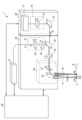
- 1A and 1B are diagrams illustrating a configuration of a laser processing system 1 and a first irradiation form of laser light.
- 1 is a diagram for explaining the focus of a laser beam in three-dimensional spatial coordinates (defocus coordinate H ⁇ 0).
- 2A to 2C are diagrams illustrating the configuration of the laser processing system 1 and a second irradiation form of laser light.
- Fig. 1 is a diagram for explaining the configuration of a laser processing system 1 and a first irradiation form of a laser beam.
- Fig. 3 is a diagram for explaining the focus of the three-dimensional spatial coordinates of the laser beam (defocus coordinate H ⁇ 0).
- the first irradiation form of the laser beam refers to a form in which the focus of the laser beam coincides with the processing location in the optical axis direction.
- the laser processing system 1 shown in FIG. 1 is a system that performs processing such as welding by irradiating a workpiece (workpiece) W placed on a moving stage (not shown) with laser light. Note that the application of the laser processing system 1 is not limited to the example of placing a workpiece on a moving stage, and can be modified as appropriate.
- a laser processing system 1 includes a laser light source 10, a processing head 20, a sensor housing 30, and a control unit 40.
- the laser light source 10 is a device that oscillates a laser internally to generate laser light in response to a command from a control unit 40 (described later).
- a fiber laser oscillator, a pulsed laser oscillator, a direct diode laser (DDL), a CO2 laser oscillator, or a solid-state laser (YAG laser) oscillator can be used as the laser light source 10.
- the laser light source 10 outputs the generated laser light to the processing head 20.
- the path of the laser light is indicated by a dashed line
- the path of the monitor light is indicated by a solid line.
- the processing head 20 is a device for irradiating the laser light output from the laser light source 10 to the workpiece W from an emission port (not shown).
- the processing head 20 is composed of a wobble head with a wobbling function (described later), a galvanometer scanner, and a polygon mirror.
- the processing head 20 is equipped with a laser light variable focus mechanism 21, a laser light deflection mechanism 22, a mirror 23, a lens 24, etc.
- the laser beam variable focus mechanism 21 is a mechanism capable of changing the focus of the laser beam output from the laser light source 10.
- the laser beam variable focus mechanism 21 controls the focus of the laser beam based on control information based on the three-dimensional spatial coordinates X, Y, Z and defocus coordinate H of the processing location commanded by the control unit 40.
- the laser beam variable focus mechanism 21 adjusts the position in the optical axis direction of a lens 26 (described later) for adjusting the focus of the laser beam so that the laser beam is focused on the three-dimensional spatial coordinates X, Y, Z of the processing location or a position shifted from that position by the defocus coordinate H, based on control information related to the distance from the laser beam outlet (not shown) to the processing location.
- the "optical axis direction” means the direction along the optical axis of the laser beam and the optical axis of the monitor light.
- the defocus coordinate (hereinafter also referred to as "defocus coordinate H") is a coordinate that indicates the amount by which the focus of the laser light is moved in the optical axis direction from a reference focus specified by three-dimensional spatial coordinates X, Y, and Z.
- the reference focus F0 of the laser light is expressed by three-dimensional spatial coordinates X, Y, and Z.
- the value of the defocus coordinate H is 0, so the focus FA of the laser light coincides with the reference focus F0 (the processing location) in the optical axis direction.
- the defocus coordinate H is not 0 (in this example, a negative value), so the focus FA of the laser light moves proximally from the reference focus F0 in the optical axis direction by the amount of the defocus coordinate H.
- the focus FA of the laser light moves distally in the optical axis direction from the reference focus F0 (not shown).
- the defocus coordinate H is a negative value, as shown in FIG. 3, the focus FA of the laser light moves proximal to the optical axis direction from the reference focus F0 (upper side in the figure).
- the focus of the laser light is defocused in, for example, operations that involve heating at a lower temperature than that used during the actual welding, such as preheating before welding or slow cooling after welding.
- the laser beam variable focus mechanism 21 includes lenses 25 and 26.
- Lenses 25 and 26 are optical components for adjusting the focus of the laser beam in the optical axis direction.
- Lens 25 has a fixed position in the optical axis direction.
- Lens 26 (focus lens) is supported so that its position in the optical axis direction is movable.
- the laser beam variable focus mechanism 21 includes a ball screw, a motor, etc. (not shown) as a mechanism for moving the position of lens 26 in the optical axis direction.
- the ball screw is a linear motion mechanism that converts the rotational motion of the motor into linear motion.
- the lens whose position is moved in the optical axis direction is not limited to lens 26, but may be lens 25, or both lenses 25 and 26 may be moved relatively.
- the mechanism for moving the focus of the laser light in the optical axis direction is not limited to a ball screw, and may be, for example, a linear motion mechanism using a linear guide, a mechanism for changing the focus by moving the position of a mirror (concave mirror), or a mechanism for changing the focus by changing the shape of a lens.
- the value of the defocus coordinate H is 0, so the focus of the laser light is the reference focus F0.
- the focus moves along the optical axis direction of the laser light depending on the value of the defocus coordinate H. Therefore, the focus of the laser light is a point located distally or proximally away from the reference focus F0, which becomes the focus FA.
- the laser beam deflection mechanism 22 is a device that controls the focal point of the laser beam A irradiated to the processing location and the focal point of the monitor beam B emitted from the processing target on the same axis.
- the laser beam deflection mechanism 22 controls the mirrors 27 and 28 (described later) in response to commands from the control unit 40.
- the laser beam deflection mechanism 22 adjusts the rotation angles of the mirrors (described later) that scan the laser beam and the monitor beam, so that the position of the laser beam A irradiated to the processing location and the position of the monitor beam B emitted from the processing location are the two-dimensional spatial coordinates X and Y, respectively, based on control information based on the two-dimensional spatial coordinates X and Y of the processing location commanded by the control unit 40. Note that in FIG. 1, the positions of the laser beam A irradiated to the processing target and the monitor beam B emitted from the processing target are shifted to make the relationship between them easier to understand, but the laser beam A and the monitor beam B are coaxial.
- the laser beam deflection mechanism 22 includes mirrors 27 and 28.
- the mirrors 27 and 28 are optical components that reflect the laser beam and the monitor beam.
- the laser beam deflection mechanism 22 also includes a drive mechanism (not shown) that rotates the mirrors 27 and 28 around their respective rotation axes. The rotation angles of the mirrors 27 and 28 are controlled by the respective drive mechanisms, so that the laser beam scans the two-dimensional space on the workpiece W.
- the monitor beam emitted from the processing location is emitted from the laser beam deflection mechanism 22 toward a sensor 31 (described later) along the same optical path as the laser beam.
- the position of the exit E (see FIG. 2/FIG. 3) of the laser beam deflection mechanism 22, which is the exit of the laser beam, is fixed.
- the mirror (reflecting portion) 23 is an optical component that reflects the laser light emitted from the laser light deflection mechanism 22, directs it to the laser light variable focus mechanism 21, and transmits the monitor light emitted from the processing area.
- the mirror 23 is composed of a dichroic mirror that reflects light of a specific wavelength and transmits light of other wavelengths.
- the lens 24 is an optical component that focuses the laser light reflected by the mirror 23 and the monitor light emitted from the laser light deflection mechanism 22.
- the sensor housing 30 is a device that guides the monitor light emitted from the processing area to the sensor 31.
- the sensor housing 30 includes the sensor 31, a monitor light variable focus mechanism 32, and a mirror 33.
- the sensor 31 is a device that receives monitor light and generates an image of the processed portion of the workpiece W.
- the sensor 31 used when monitoring laser welding may be a camera, a photodiode (PD), or the like.
- the camera is used, for example, to receive infrared light emitted from the welded portion during laser welding and monitor the state of the keyhole and molten pool.
- the photodiode is used, for example, to receive infrared light emitted from the welded portion during laser welding and estimate the temperature of the welded portion from the radiated light.
- the photodiode is also used, for example, to receive visible light emitted from the welded portion during laser welding and observe the presence or absence of plasma light generated in the event of poor welding.
- the monitor light variable focus mechanism 32 is a mechanism capable of changing the focus of the monitor light.
- the monitor light variable focus mechanism 32 controls the focus of the monitor light based on control information based on the three-dimensional spatial coordinates X, Y, and Z of the processing location, which is commanded by the control unit 40.
- the monitor light variable focus mechanism 32 adjusts the position in the optical axis direction of a lens 34 (described below) for adjusting the focus of the monitor light, so that the monitor light is focused on the three-dimensional spatial coordinates X, Y, and Z of the processing location, based on control information related to the distance from the laser light emission port E (see Figures 2 and 3) to the processing location.
- the monitor light variable focus mechanism 32 includes a lens 34.
- the lens 34 (focus lens) is an optical component for adjusting the focus of the monitor light.
- the lens 34 is supported so that its position in the optical axis direction is freely movable.
- the monitor light variable focus mechanism 32 includes a ball screw, a motor, etc. (not shown) as a mechanism for moving the position of the lens 34 in the optical axis direction.
- the ball screw is a linear motion mechanism that converts the rotational motion of the motor into linear motion.
- the mechanism for moving the focus of the monitor light in the optical axis direction is not limited to a ball screw, but can be, for example, a linear motion mechanism using a linear guide, a mechanism for changing the focus by moving the position of a mirror (concave mirror), or a mechanism for changing the focus by changing the shape of a lens.
- the control information based on the three-dimensional spatial coordinates X, Y, Z of the processing location commanded from the control unit 40 to the monitor light variable-focus mechanism 32 is the same as the control information based on the three-dimensional spatial coordinates X, Y, Z of the processing location commanded from the control unit 40 to the laser light variable-focus mechanism 21. Therefore, in a first irradiation form of the laser light (described later), the focus of the three-dimensional spatial coordinates of the monitor light coincides with the focus of the three-dimensional spatial coordinates of the laser light at the processing location.
- the mirror 33 is an optical member for making the monitor light transmitted through the mirror (reflecting portion) 23 incident on the monitor light variable focus mechanism 32 .
- the control unit 40 controls the focus of the laser light in the laser light variable focus mechanism 21, the position of the laser light and the monitor light in the laser light deflection mechanism 22, and the focus of the monitor light in the monitor light variable focus mechanism 32. Specifically, the control unit 40 controls the position of the lens in the optical axis direction for adjusting the focus of the laser light by sending control information based on the three-dimensional spatial coordinates X, Y, and Z of the processing location and the defocus coordinate H as a command to the laser light variable focus mechanism 21. The control unit 40 also controls the rotation angle of the mirror that scans the laser light and the monitor light in two-dimensional space by sending control information based on the two-dimensional spatial coordinates X and Y of the processing location as a command to the laser light deflection mechanism 22.
- control unit 40 controls the position of the lens in the optical axis direction for adjusting the focus of the monitor light by sending control information based on the three-dimensional spatial coordinates X, Y, and Z of the processing location as a command to the monitor light variable focus mechanism 32.
- the command sent from the control unit 40 to the laser beam variable focus mechanism 21, the laser beam deflection mechanism 22, and the monitor beam variable focus mechanism 32 may include, in addition to the above-mentioned control information, a speed command indicating the operating speed of the lenses, mirrors, etc.
- the operating speed of the lenses, mirrors, etc. is set based on the speed command from the control unit 40.
- the control unit 40 is composed of a computer equipped with memories such as ROM and RAM, a CPU, and a communication control unit.
- the control unit 40 executes various functions in cooperation with each piece of hardware by appropriately reading and executing an operating system (OS) and various application programs stored in an external memory.
- the control unit 40 may be composed of a CNC (Computer Numerical Controller), a PLC (Programmable Logic Controller), etc., and may be connected to a higher-level computer that outputs machining conditions in addition to machining programs.
- Fig. 4 is a diagram explaining the configuration of the laser processing system 1 and the second irradiation form of the laser light. Note that the second irradiation form of the laser light refers to a form in which the focus of the laser light is shifted from the processing location in the optical axis direction.
- the laser beam variable focus mechanism 21 since the value of the defocus coordinate H is 0, the laser beam variable focus mechanism 21 does not control the movement of the focus of the laser beam from the reference focus F0 in the optical axis direction.
- the laser beam variable focus mechanism 21 controls the focus of the laser beam to coincide with the three-dimensional spatial coordinates X, Y, Z based on the control information commanded by the control unit 40.
- the control unit 40 transmits control information based on the two-dimensional spatial coordinates X, Y of the processing location as a command to the laser light deflection mechanism 22.
- the laser light deflection mechanism 22 controls the two-dimensional spatial position of the laser light so that the focus of the laser light coincides with the processing location.
- the control unit 40 transmits control information based on the three-dimensional spatial coordinates X, Y, Z of the processing location as a command to the monitor light variable focus mechanism 32.
- the monitor light variable focus mechanism 32 controls the focus of the monitor light so that it coincides with the processing location.
- the focus FA of the laser light A and the focus FB of the monitor light B coincide at the reference focus F0 (the processing location).
- the focus of the monitor light coincides with the focus of the laser light, so the operator can monitor the quality of the processing location by the laser light by viewing the focused image.
- the control unit 40 transmits control information based on the three-dimensional spatial coordinates X, Y, Z and defocus coordinate H of the processing location as a command to the laser beam variable focus mechanism 21.
- control information based on the three-dimensional spatial coordinates X, Y, Z and defocus coordinate H of the processing location as a command to the laser beam variable focus mechanism 21.
- the defocus coordinate H becomes a negative value.
- the laser beam variable focus mechanism 21 controls the focus of the laser beam in response to the command transmitted from the control unit 40 so that the focus of the laser beam moves from the position coinciding with the three-dimensional spatial coordinates X, Y, Z to the proximal side by the amount of the defocus coordinate H (negative value).
- the control unit 40 transmits the two-dimensional spatial coordinates X, Y of the processing location as a command to the laser light deflection mechanism 22.
- the laser light deflection mechanism 22 controls the two-dimensional spatial position of the laser light so that the focus of the laser light coincides with the processing location.
- the control unit 40 transmits the three-dimensional spatial coordinates X, Y, Z of the processing location as a command to the monitor light variable focus mechanism 32.
- the monitor light variable focus mechanism 32 controls the position of the monitor light in the optical axis direction so that the focus of the monitor light coincides with the processing location.
- the focus of the laser light moves proximally from the reference focus F0 (the processing location) by the amount of defocus coordinate H.
- the focus of the monitor light coincides with the processing location.
- the focus of the monitor light coincides with the reference focus F0 regardless of where the focus of the laser light moves in the optical axis direction. Therefore, the sensor 31 can generate a focused image as an image of the processing location by the laser light, even while the focus of the laser light is shifted in the optical axis direction to heat the processing location.
- the focus of the monitor light can always be aligned with the processing location even when the focus of the laser light is shifted in the optical axis direction. Therefore, the operator can monitor the quality of the processing location by the laser light using a focused image, even while the operator is performing the task of heating the processing location by shifting the focus of the laser light in the optical axis direction.
- the laser light used for laser welding and the monitor light for monitoring the processed area have different wavelengths.
- the wavelength of the laser light is 1070 nm
- the wavelength of the monitor light is 400 to 600 nm, 800 to 900 nm, or 1300 to 1500 nm.
- the refractive index for the lens also differs, so that the focal points of the laser light and the monitor light may not coincide even if the same control information is transmitted from the control unit 40.
- the lens control information based on three-dimensional spatial coordinates is the motor rotation angle calculated by the following equation (1).
- Motor rotation angle (target position ⁇ first conversion coefficient)+second conversion coefficient (1)
- the target position is the focal position of the laser light (X, Y, Z or X, Y, Z, H).
- the first conversion coefficient is a coefficient for calculating the rotation angle of the motor required to move the lens to the target position.
- the first conversion coefficient differs depending on the lens specifications (type).
- the second conversion coefficient is a coefficient for correcting the installation position of the lens and the positions of the reference focus F0 and the focus FB.
- the control unit 40 sets the first conversion coefficient according to the specifications of each lens. Also, if the specifications of the lens for adjusting the focus of the laser light and the specifications of the lens for adjusting the focus of the monitor light are the same or have similar optical characteristics, the control unit 40 sets the value of the first conversion coefficient according to the lens specifications and sets the value of the second conversion coefficient according to the wavelengths of the laser light and the monitor light.
- the focal points of the laser light and the monitor light can be aligned. Therefore, even if the wavelength of the light used differs depending on the sensor specifications, the focus of the monitor light can be more appropriately adjusted.
- Wobbling is a technique for performing welding while moving the focal position of a laser beam at high speed.
- the speed command is faster than normal, so the lens 26 moves at high speed in the laser beam variable focus mechanism 21.
- the monitor beam variable focus mechanism 32 no problem occurs when monitoring the processing location even if the movement of the monitor beam does not follow the movement of the laser beam. Therefore, when the speed command is equal to or greater than a preset value, as in laser welding by wobbling, the speed command sent from the control unit 40 to the monitor beam variable focus mechanism 32 is made relatively smaller than the speed command sent to the laser beam deflection mechanism 22. This can extend the life of the ball screw as a linear motion mechanism constituting the monitor beam variable focus mechanism 32, making it possible to operate the system more stably.
- the focus of the monitor light is controlled in the monitor light variable focus mechanism 32 by control information based on the three-dimensional spatial coordinates X, Y, and Z of the processing location, but this is not limiting.
- the focus of the monitor light in the monitor light variable focus mechanism 32 may also be controlled by control information based on the three-dimensional spatial coordinates X, Y, and Z of the processing location and the defocus coordinate H.
- the focus of the laser light and the focus of the monitor light are controlled coaxially in the laser light deflection mechanism 22 using control information based on the two-dimensional spatial coordinates X, Y of the processing location, but this is not limiting.
- the focus of the laser light and the focus of the monitor light may also be controlled coaxially using control information based on the three-dimensional spatial coordinates X, Y, Z of the processing location.
- a laser beam variable focus mechanism (21) capable of changing the focus of a laser beam output from a laser light source by control information based on the three-dimensional spatial coordinates of a processing location
- a laser beam deflection mechanism (22) for coaxially controlling the position of the laser beam irradiated to the processing location and the position of a monitor beam emitted from the processing location
- a sensor (31) for receiving the monitor beam
- a reflection unit (23) for reflecting the laser beam emitted from the laser beam variable focus mechanism and guiding it to the laser beam deflection mechanism, and for transmitting the monitor beam emitted from the processing location and guiding it to the sensor
- a focus of the monitor beam capable of changing the focus of the monitor beam by control information based on the three-dimensional spatial coordinates of the processing location.
- control unit for controlling the focus of the laser light in the laser light variable focus mechanism, the positions of the laser light and the monitor light in the laser light deflection mechanism, and the focus of the monitor light in the monitor light variable focus mechanism, wherein the control unit controls the focus of the laser light in the laser light variable focus mechanism using control information based on three-dimensional spatial coordinates of a processing location and defocus coordinates of the laser light, and controls the focus of the monitor light in the monitor light variable focus mechanism using control information based on at least the three-dimensional spatial coordinates of the processing location.
- the control unit (40) sets a conversion coefficient used to adjust the focus of the laser light in controlling the laser light variable focus mechanism (21) and a conversion coefficient used to control the focus of the monitor light in controlling the monitor light variable focus mechanism to different values. (Appendix 3) When the speed command for the laser beam variable focus mechanism (21) is equal to or greater than a preset value, the control unit (40) sets the speed command for the monitor beam variable focus mechanism (32) to be relatively smaller than the speed command for the laser beam variable focus mechanism.
Landscapes
- Physics & Mathematics (AREA)
- Optics & Photonics (AREA)
- Engineering & Computer Science (AREA)
- Plasma & Fusion (AREA)
- Mechanical Engineering (AREA)
- Laser Beam Processing (AREA)
Abstract
Description
図1は、レーザ加工システム1の構成とレーザ光の第1の照射形態を説明する図である。図2は、レーザ光の三次元空間座標の焦点(デフォーカス座標H=0)を説明する図である。図3は、レーザ光の三次元空間座標の焦点(デフォーカス座標H≠0)を説明する図である。なお、レーザ光の第1の照射形態とは、レーザ光の焦点が光軸方向において加工箇所と一致している形態をいう。
レーザ光源10は、制御部40(後述)からの指令に応じて、内部でレーザを発振し、レーザ光を生成する装置である。レーザ光源10としては、例えば、ファイバレーザ発振器、パルスレーザ発振器、ダイレクトダイオードレーザ(DDL)、CO2レーザ発振器又は固体レーザ(YAGレーザ)発振器等を用いることができる。レーザ光源10は、生成したレーザ光を加工ヘッド20に出力する。なお、図1においては、レーザ光の経路を破線で示し、モニタ光の経路を実線で示す。
ミラー33は、ミラー(反射部)23を透過したモニタ光を、モニタ光可変焦点機構32に入射させるための光学部材である。
レーザ溶接に用いるレーザ光と、加工箇所をモニタするためのモニタ光は、それぞれ波長が異なる。例えば、レーザ光の波長は、1070nmであり、モニタ光の波長は、400~600nm、800~900nm、1300~1500nmである。このように、使用する光の波長が異なると、レンズに対する屈折率にも差が生じるため、制御部40から同じ制御情報を送信しても、レーザ光とモニタ光のそれぞれの焦点が一致しないこともある。
モータの回転角度=(目標位置×第1変換係数)+第2変換係数・・・(1)
ここで、目標位置は、レーザ光の焦点位置(X、Y、Z又はX、Y、Z、H)である。第1変換係数は、レンズを目標位置まで移動させるのに必要なモータの回転角度を算出するための係数である。第1変換係数は、レンズの仕様(形式)により異なる。第2変換係数は、レンズの設置位置や基準焦点F0と焦点FBの位置を補正するための係数である。
レーザ溶接においては、ウォブリングと呼ばれる手法により溶接を行うことがある。ウォブリングとは、レーザ光の焦点位置を高速で移動させながら溶接を行う手法である。ウォブリングによりレーザ溶接する際、通常よりも速度指令が速くなるため、レーザ光可変焦点機構21では、レンズ26が高速で移動する。一方、モニタ光可変焦点機構32では、モニタ光の移動をレーザ光の移動に追従させなくても、加工箇所をモニタする場合に問題は生じない。そこで、ウォブリングによるレーザ溶接のように、速度指令が予め設定された値以上となる場合、制御部40からモニタ光可変焦点機構32に送信する速度指令を、レーザ光偏向機構22に送信する速度指令よりも相対的に小さくする。これにより、モニタ光可変焦点機構32を構成する直動機構としてのボールねじの寿命を延ばすことができるため、システムをより安定的に稼働させることが可能となる。
以上、本開示の実施形態について説明したが、本開示は、前述した実施形態に限定されるものではない。これらの実施形態は、本開示の要旨を逸脱しない範囲で、又は、特許請求の範囲に記載された内容とその均等物から導き出される本開示の趣旨を逸脱しない範囲で、種々の追加、置き換え、変更、部分的削除等が可能である。また、これらの実施形態は、組み合わせて実施することもできる。例えば、上述した実施形態において、各動作の順序や各処理の順序は、一例として示したものであり、これらに限定されるものではない。
(付記1)
レーザ光源から出力されるレーザ光の焦点を、加工箇所の三次空間座標に基づく制御情報により変更可能なレーザ光可変焦点機構(21)と、加工箇所へ照射するレーザ光の位置及び加工箇所から放出されるモニタ光の位置を同軸で制御するレーザ光偏向機構(22)と、モニタ光を受光するセンサ(31)と、前記レーザ光可変焦点機構から出射されるレーザ光を反射して前記レーザ光偏向機構へ導き、加工箇所から放出されるモニタ光を透過させて前記センサへ導く反射部(23)と、モニタ光の焦点を、加工箇所の三次空間座標に基づく制御情報により変更可能なモニタ光可変焦点機構(32)と、前記レーザ光可変焦点機構におけるレーザ光の焦点、前記レーザ光偏向機構におけるレーザ光及びモニタ光の位置、前記モニタ光可変焦点機構におけるモニタ光の焦点を制御するための制御部(40)と、を備え、前記制御部は、加工箇所の三次元空間座標及びレーザ光のデフォーカス座標に基づく制御情報により、前記レーザ光可変焦点機構におけるレーザ光の焦点を制御し、少なくとも加工箇所の三次空間座標に基づく制御情報により、前記モニタ光可変焦点機構におけるモニタ光の焦点を制御するレーザ加工システム。
(付記2)
前記制御部(40)は、前記レーザ光可変焦点機構(21)の制御においてレーザ光の焦点を調節するために用いる変換係数と、前記モニタ光可変焦点機構の制御においてモニタ光の焦点を制御するために用いる変換係数を、それぞれ異なる値に設定する。
(付記3)
前記制御部(40)は、前記レーザ光可変焦点機構(21)に対する速度指令が予め設定された値以上となる場合、前記モニタ光可変焦点機構(32)に対する速度指令を、前記レーザ光可変焦点機構に対する速度指令よりも相対的に小さくする。
Claims (3)
- レーザ光源から出力されるレーザ光の焦点を、加工箇所の三次空間座標に基づく制御情報により変更可能なレーザ光可変焦点機構と、
加工箇所へ照射するレーザ光の位置及び加工箇所から放出されるモニタ光の位置を同軸で制御するレーザ光偏向機構と、
モニタ光を受光するセンサと、
前記レーザ光可変焦点機構から出射されるレーザ光を反射して前記レーザ光偏向機構へ導き、加工箇所から放出されるモニタ光を透過させて前記センサへ導く反射部と、
モニタ光の焦点を、加工箇所の三次空間座標に基づく制御情報により変更可能なモニタ光可変焦点機構と、
前記レーザ光可変焦点機構におけるレーザ光の焦点、前記レーザ光偏向機構におけるレーザ光及びモニタ光の位置、前記モニタ光可変焦点機構におけるモニタ光の焦点を制御するための制御情報を生成する制御部と、を備え、
前記制御部は、
加工箇所の三次元空間座標及びレーザ光のデフォーカス座標に基づく制御情報により、前記レーザ光可変焦点機構におけるレーザ光の焦点を制御し、
少なくとも加工箇所の三次空間座標に基づく制御情報により、前記モニタ光可変焦点機構におけるモニタ光の焦点を制御するレーザ加工システム。 - 前記制御部は、
前記レーザ光可変焦点機構の制御においてレーザ光の焦点を調節するために用いる変換係数と、前記モニタ光可変焦点機構の制御においてモニタ光の焦点を制御するために用いる変換係数を、それぞれ異なる値に設定する、請求項1に記載のレーザ加工システム。 - 前記制御部は、
前記レーザ光可変焦点機構に対する速度指令が予め設定された値以上となる場合、前記モニタ光可変焦点機構に対する速度指令を、前記レーザ光可変焦点機構に対する速度指令よりも相対的に小さくする、請求項1又は2に記載のレーザ加工システム。
Priority Applications (4)
| Application Number | Priority Date | Filing Date | Title |
|---|---|---|---|
| CN202380097886.3A CN121175142A (zh) | 2023-06-26 | 2023-06-26 | 激光加工系统 |
| JP2025529025A JPWO2025004152A1 (ja) | 2023-06-26 | 2023-06-26 | |
| DE112023006031.2T DE112023006031T5 (de) | 2023-06-26 | 2023-06-26 | Laserbearbeitungssystem |
| PCT/JP2023/023640 WO2025004152A1 (ja) | 2023-06-26 | 2023-06-26 | レーザ加工システム |
Applications Claiming Priority (1)
| Application Number | Priority Date | Filing Date | Title |
|---|---|---|---|
| PCT/JP2023/023640 WO2025004152A1 (ja) | 2023-06-26 | 2023-06-26 | レーザ加工システム |
Publications (1)
| Publication Number | Publication Date |
|---|---|
| WO2025004152A1 true WO2025004152A1 (ja) | 2025-01-02 |
Family
ID=93937996
Family Applications (1)
| Application Number | Title | Priority Date | Filing Date |
|---|---|---|---|
| PCT/JP2023/023640 Ceased WO2025004152A1 (ja) | 2023-06-26 | 2023-06-26 | レーザ加工システム |
Country Status (4)
| Country | Link |
|---|---|
| JP (1) | JPWO2025004152A1 (ja) |
| CN (1) | CN121175142A (ja) |
| DE (1) | DE112023006031T5 (ja) |
| WO (1) | WO2025004152A1 (ja) |
Citations (4)
| Publication number | Priority date | Publication date | Assignee | Title |
|---|---|---|---|---|
| JP2000312984A (ja) * | 1999-04-27 | 2000-11-14 | Sekisui Chem Co Ltd | レーザ装置 |
| JP2008012869A (ja) * | 2006-07-07 | 2008-01-24 | Shizuoka Prefecture | レーザマーキング方法 |
| JP2012148316A (ja) * | 2011-01-19 | 2012-08-09 | Keyence Corp | レーザー加工装置 |
| JP2016126232A (ja) * | 2015-01-07 | 2016-07-11 | キヤノン株式会社 | 撮像装置、その制御方法、および制御プログラム |
-
2023
- 2023-06-26 CN CN202380097886.3A patent/CN121175142A/zh active Pending
- 2023-06-26 WO PCT/JP2023/023640 patent/WO2025004152A1/ja not_active Ceased
- 2023-06-26 DE DE112023006031.2T patent/DE112023006031T5/de active Pending
- 2023-06-26 JP JP2025529025A patent/JPWO2025004152A1/ja active Pending
Patent Citations (4)
| Publication number | Priority date | Publication date | Assignee | Title |
|---|---|---|---|---|
| JP2000312984A (ja) * | 1999-04-27 | 2000-11-14 | Sekisui Chem Co Ltd | レーザ装置 |
| JP2008012869A (ja) * | 2006-07-07 | 2008-01-24 | Shizuoka Prefecture | レーザマーキング方法 |
| JP2012148316A (ja) * | 2011-01-19 | 2012-08-09 | Keyence Corp | レーザー加工装置 |
| JP2016126232A (ja) * | 2015-01-07 | 2016-07-11 | キヤノン株式会社 | 撮像装置、その制御方法、および制御プログラム |
Also Published As
| Publication number | Publication date |
|---|---|
| CN121175142A (zh) | 2025-12-19 |
| JPWO2025004152A1 (ja) | 2025-01-02 |
| DE112023006031T5 (de) | 2026-01-08 |
Similar Documents
| Publication | Publication Date | Title |
|---|---|---|
| JP7154132B2 (ja) | ビーム位置合わせ及び/又はウォブル移動を提供するデュアル可動ミラーを有するレーザー切断ヘッド | |
| KR100962817B1 (ko) | 레이저 용접 장치 및 그 방법 | |
| JP4988160B2 (ja) | レーザ溶接装置、レーザ溶接システム、およびレーザ溶接方法 | |
| JP5114874B2 (ja) | レーザ溶接方法およびレーザ溶接装置 | |
| US20070278194A1 (en) | Laser Device And Operating Method | |
| KR20180018769A (ko) | 빔 이동을 제공하는 이중 가동 미러를 갖는 레이저 용접 헤드 | |
| JP7696107B2 (ja) | レーザ溶接装置およびレーザ溶接方法 | |
| US20240157470A1 (en) | Laser processing device | |
| US20240149376A1 (en) | Laser processing device | |
| WO2025004152A1 (ja) | レーザ加工システム | |
| JP7833648B2 (ja) | レーザ加工装置 | |
| US20220395925A1 (en) | Method for laser machining a workpiece and associated laser machining system | |
| JP7503764B2 (ja) | レーザ装置およびレーザ装置の制御方法 | |
| JP7554973B2 (ja) | レーザ加工装置 | |
| JP3970501B2 (ja) | レーザ加工装置 | |
| JP2025069549A (ja) | レーザ加工ヘッド及びそれを備えたレーザ加工装置、第1レーザ光及び第2レーザ光の集光位置の調整方法 | |
| JP2817555B2 (ja) | レーザ加工機 | |
| WO2025027686A1 (ja) | レーザ加工装置 | |
| JP2022098255A (ja) | レーザ加工装置及びレーザ照射装置 | |
| JP2023112742A (ja) | レーザ溶接装置及びこれを用いたレーザ溶接方法 | |
| JP2024180163A (ja) | レーザー溶接ヘッド | |
| JP2025122398A (ja) | レーザ加工装置 | |
| JPH01241390A (ja) | レーザ加工装置 |
Legal Events
| Date | Code | Title | Description |
|---|---|---|---|
| 121 | Ep: the epo has been informed by wipo that ep was designated in this application |
Ref document number: 23943554 Country of ref document: EP Kind code of ref document: A1 |
|
| ENP | Entry into the national phase |
Ref document number: 2025529025 Country of ref document: JP Kind code of ref document: A |
|
| WWE | Wipo information: entry into national phase |
Ref document number: 2025529025 Country of ref document: JP |
|
| WWE | Wipo information: entry into national phase |
Ref document number: 112023006031 Country of ref document: DE |
|
| WWP | Wipo information: published in national office |
Ref document number: 112023006031 Country of ref document: DE |