WO2024262113A1 - 純水製造装置 - Google Patents
純水製造装置 Download PDFInfo
- Publication number
- WO2024262113A1 WO2024262113A1 PCT/JP2024/011728 JP2024011728W WO2024262113A1 WO 2024262113 A1 WO2024262113 A1 WO 2024262113A1 JP 2024011728 W JP2024011728 W JP 2024011728W WO 2024262113 A1 WO2024262113 A1 WO 2024262113A1
- Authority
- WO
- WIPO (PCT)
- Prior art keywords
- water production
- boost pump
- pressure
- water
- value
- Prior art date
- Legal status (The legal status is an assumption and is not a legal conclusion. Google has not performed a legal analysis and makes no representation as to the accuracy of the status listed.)
- Ceased
Links
Images








Classifications
-
- C—CHEMISTRY; METALLURGY
- C02—TREATMENT OF WATER, WASTE WATER, SEWAGE, OR SLUDGE
- C02F—TREATMENT OF WATER, WASTE WATER, SEWAGE, OR SLUDGE
- C02F1/00—Treatment of water, waste water, or sewage
- C02F1/46—Treatment of water, waste water, or sewage by electrochemical methods
- C02F1/469—Treatment of water, waste water, or sewage by electrochemical methods by electrochemical separation, e.g. by electro-osmosis, electrodialysis, electrophoresis
- C02F1/4693—Treatment of water, waste water, or sewage by electrochemical methods by electrochemical separation, e.g. by electro-osmosis, electrodialysis, electrophoresis electrodialysis
- C02F1/4695—Treatment of water, waste water, or sewage by electrochemical methods by electrochemical separation, e.g. by electro-osmosis, electrodialysis, electrophoresis electrodialysis electrodeionisation
-
- B—PERFORMING OPERATIONS; TRANSPORTING
- B01—PHYSICAL OR CHEMICAL PROCESSES OR APPARATUS IN GENERAL
- B01D—SEPARATION
- B01D61/00—Processes of separation using semi-permeable membranes, e.g. dialysis, osmosis or ultrafiltration; Apparatus, accessories or auxiliary operations specially adapted therefor
- B01D61/42—Electrodialysis; Electro-osmosis ; Electro-ultrafiltration; Membrane capacitive deionization
- B01D61/44—Ion-selective electrodialysis
-
- B—PERFORMING OPERATIONS; TRANSPORTING
- B01—PHYSICAL OR CHEMICAL PROCESSES OR APPARATUS IN GENERAL
- B01D—SEPARATION
- B01D61/00—Processes of separation using semi-permeable membranes, e.g. dialysis, osmosis or ultrafiltration; Apparatus, accessories or auxiliary operations specially adapted therefor
- B01D61/42—Electrodialysis; Electro-osmosis ; Electro-ultrafiltration; Membrane capacitive deionization
- B01D61/44—Ion-selective electrodialysis
- B01D61/46—Apparatus therefor
- B01D61/48—Apparatus therefor having one or more compartments filled with ion-exchange material, e.g. electrodeionisation
-
- B—PERFORMING OPERATIONS; TRANSPORTING
- B01—PHYSICAL OR CHEMICAL PROCESSES OR APPARATUS IN GENERAL
- B01D—SEPARATION
- B01D61/00—Processes of separation using semi-permeable membranes, e.g. dialysis, osmosis or ultrafiltration; Apparatus, accessories or auxiliary operations specially adapted therefor
- B01D61/42—Electrodialysis; Electro-osmosis ; Electro-ultrafiltration; Membrane capacitive deionization
- B01D61/44—Ion-selective electrodialysis
- B01D61/52—Accessories; Auxiliary operation
-
- B—PERFORMING OPERATIONS; TRANSPORTING
- B01—PHYSICAL OR CHEMICAL PROCESSES OR APPARATUS IN GENERAL
- B01D—SEPARATION
- B01D61/00—Processes of separation using semi-permeable membranes, e.g. dialysis, osmosis or ultrafiltration; Apparatus, accessories or auxiliary operations specially adapted therefor
- B01D61/42—Electrodialysis; Electro-osmosis ; Electro-ultrafiltration; Membrane capacitive deionization
- B01D61/44—Ion-selective electrodialysis
- B01D61/54—Controlling or regulating
-
- C—CHEMISTRY; METALLURGY
- C02—TREATMENT OF WATER, WASTE WATER, SEWAGE, OR SLUDGE
- C02F—TREATMENT OF WATER, WASTE WATER, SEWAGE, OR SLUDGE
- C02F1/00—Treatment of water, waste water, or sewage
- C02F1/46—Treatment of water, waste water, or sewage by electrochemical methods
- C02F1/469—Treatment of water, waste water, or sewage by electrochemical methods by electrochemical separation, e.g. by electro-osmosis, electrodialysis, electrophoresis
-
- C—CHEMISTRY; METALLURGY
- C02—TREATMENT OF WATER, WASTE WATER, SEWAGE, OR SLUDGE
- C02F—TREATMENT OF WATER, WASTE WATER, SEWAGE, OR SLUDGE
- C02F2103/00—Nature of the water, waste water, sewage or sludge to be treated
- C02F2103/02—Non-contaminated water, e.g. for industrial water supply
- C02F2103/04—Non-contaminated water, e.g. for industrial water supply for obtaining ultra-pure water
-
- C—CHEMISTRY; METALLURGY
- C02—TREATMENT OF WATER, WASTE WATER, SEWAGE, OR SLUDGE
- C02F—TREATMENT OF WATER, WASTE WATER, SEWAGE, OR SLUDGE
- C02F2201/00—Apparatus for treatment of water, waste water or sewage
- C02F2201/002—Construction details of the apparatus
- C02F2201/005—Valves
Definitions
- the present invention relates to a pure water production system.
- EDI equipment is expensive, with a complex structure and many components compared to ion exchange resin equipment. Therefore, in order to keep the processing costs of pure water production as low as possible, attempts are being made to increase the amount of water processed per unit time by processing the water at a high flow rate. When the number of EDI equipment is increased in multi-stage processing, the demand for a faster flow rate becomes even higher.
- Increasing the flow rate of the liquid passing through the EDI device increases the difference in pressure between the liquid upstream and downstream of the EDI device (water flow differential pressure).
- water flow differential pressure When producing pure water through a multi-stage process, increasing the flow rate of the liquid passing through each of the multiple EDI devices increases the water flow differential pressure of each EDI device.
- the previous EDI device is supplied with an excessively high pressure liquid, which may damage the EDI device.
- EDI devices generally have a structure in which plastic frames are stacked, and have structural characteristics that make them relatively low in pressure resistance, so they tend to be easily damaged when high-pressure liquid is supplied. Therefore, if liquid is supplied at a pressure that is not excessive in order to prevent damage to the EDI device in the previous stage, the EDI device in the subsequent stage cannot obtain a supply water pressure that can achieve a sufficiently fast flow rate, and the effect of reducing treatment costs is reduced.
- another deionized water production device such as an ion exchange resin device or a boron selective resin device
- the object of the present invention is to provide a pure water production system that can achieve a sufficiently high flow rate in each deionized water production device and prevent damage to the deionized water production device due to excessively high pressure.
- the pure water production system of the present invention includes a boost pump disposed between deionized water production devices, and a pressure gauge disposed between the boost pump and the deionized water production device located upstream of the boost pump, the boost pump and at least one of the deionized water production devices located upstream of the pressure gauge are electrically regenerated deionized water production devices, and the boost pump starts and stops at least one of its operations based on the measurement value of the pressure gauge.
- This configuration also includes cases where other devices (e.g., ultraviolet oxidation devices, tanks, pumps) are disposed between the deionized water production devices in addition to the boost pump.
- the boost pump may start operating when the measured value of the pressure gauge increases from a value below a first set pressure value to equal to or greater than the first set pressure value while the boost pump is stopped.
- the boost pump may stop operating when the pressure gauge reading falls from a value exceeding a second set pressure value to equal to or less than the second set pressure value during operation of the boost pump, and may start operating when the pressure gauge reading increases from a value below a first set pressure value to equal to or more than the first set pressure value during stoppage of operation of the boost pump, and the first set pressure value may be a value greater than the second set pressure value.
- the second set pressure value may be a value within a range of 0.00 MPa to 0.05 MPa.
- the first set pressure value may be a value within a range of 0.02 MPa to 0.1 MPa.
- the boost pump may start operating when a set time has elapsed since the start of liquid delivery to the inlet of the boost pump while the boost pump is stopped.
- the supply pump disposed upstream of the deionized water production apparatus located at the forefront stage may stop operating at the same time as the boost pump stops operating.
- Pure water may be produced in a state in which the water flow differential pressure of at least one of the multiple deionized water production devices is greater than 0.20 MPa, and the sum of the pressure at the inlet of the desalting compartment of the electrically regenerated deionized water production device located upstream of the boost pump and the pressure at the outlet of the boost pump is greater than 1.5 times the pressure value at the inlet of the desalting compartment of the electrically regenerated deionized water production device.
- a switching valve is provided upstream of the deionized water production apparatus on the upstream side of the boost pump to switch between a water supply line that supplies treated water to the deionized water production apparatus and a circulation line that returns the treated water to the upstream side of a supply pump located upstream of the deionized water production apparatus located at the front stage, and a switching valve is provided downstream of the deionized water production apparatus on the downstream side of the boost pump to switch between a water supply line that sends treated water outside the deionized water production apparatus and another circulation line that returns the treated water to the upstream side of the supply pump, and at least one of the switching valves may be a three-way valve.
- the present invention makes it possible to achieve a sufficiently high flow rate in each deionized water production device while preventing damage to the deionized water production device due to excessively high pressure.
- FIG. 1 is a block diagram showing a schematic diagram of a pure water producing apparatus according to a first embodiment of the present invention
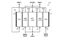
- FIG. 2 is a cross-sectional view showing a schematic example of the internal configuration of a single deionization chamber type EDI device.
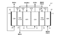
- FIG. 2 is a cross-sectional view showing a schematic example of the internal configuration of a two-deionization chamber type EDI device.
- FIG. 1 is a block diagram illustrating a pure water production system according to a first comparative example.
- FIG. 1 is a graph showing the relationship between the ratio of the actual flow rate of the EDI device to the standard flow rate and the water flow differential pressure in the desalting compartment.
- FIG. 6 is a cross-sectional view showing a schematic diagram of a deionization compartment of the two-deionization compartment type EDI device of the pure water production apparatus shown in FIG. 5 .
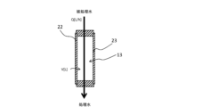
- FIG. 2 is a cross-sectional view showing a schematic diagram of a deionization compartment of a single-deionization-compartment type EDI device.
- FIG. 11 is a block diagram illustrating a pure water producing apparatus according to a second comparative example.
- FIG. 11 is a graph showing the relationship between the measured values of the pressure gauges and the elapsed time when pure water is produced using the pure water producing apparatus shown in FIG. 10 .
- FIG. 4 is a block diagram illustrating a pure water production system according to a second embodiment of the present invention.
- FIG. 11 is a block diagram illustrating a pure water production system according to a third embodiment of the present invention.
- FIG. 13 is a block diagram illustrating a pure water production system according to a fourth embodiment of the present invention.
- FIG. 1 is a block diagram showing a basic configuration of a pure water production system according to a first embodiment of the present invention.
- two deionized water production apparatuses 1 and 2 are connected in series, and a booster pump 3 and a pressure gauge 4 are provided between the deionized water production apparatuses 1 and 2.
- the front-stage deionized water production apparatus 1 is an EDI apparatus (electrically regenerated deionized water production apparatus).
- the rear-stage deionized water production apparatus 2 may be an EDI apparatus or another deionized water production apparatus (e.g., an ion exchange resin apparatus or a boron selective resin apparatus).
- an EDI apparatus e.g., an ion exchange resin apparatus or a boron selective resin apparatus.
- an example will be described in which both the front-stage deionized water production apparatus 1 and the rear-stage deionized water production apparatus 2 are EDI apparatuses.
- EDI devices generally have a configuration in which a desalting compartment separated by a pair of ion exchange membranes is provided between an anode and a cathode, and the desalting compartment is filled with ion exchange resin.
- the EDI devices 1 and 2 illustrated in FIG. 2 have a single desalting compartment type configuration with a single desalting compartment 13, and a concentration compartment 24, desalting compartment 13, and concentration compartment 25 are provided, in order from the anode compartment 20 side, between an anode compartment 20 equipped with an anode 18 and a cathode compartment 21 equipped with a cathode 19.
- the anode compartment 20 and the concentration compartment 24 are adjacent to each other across a cation exchange membrane (CEM) 26, the concentration compartment 24 and desalting compartment 13 are adjacent to each other across an anion exchange membrane (AEM) 22, the desalting compartment 13 and the concentration compartment 25 are adjacent to each other across a cation exchange membrane 23, and the concentration compartment 25 and the cathode compartment 21 are adjacent to each other across an anion exchange membrane 27.
- the deionization chamber 13 is filled with an ion exchange resin (generally including an anion exchange resin (AER) and a cation exchange resin (CER)).
- the anode chamber 20 is filled with a cation exchange resin
- the cathode chamber 21 is filled with an anion exchange resin.
- the EDI devices 1 and 2 perform a desalination (deionization) process on the water to be treated when the water to be treated is supplied to the deionization chamber 13 with a DC voltage applied between the anode 18 and the cathode 19.
- a desalination process on the water to be treated when the water to be treated is supplied to the deionization chamber 13 with a DC voltage applied between the anode 18 and the cathode 19.
- water from which ionic components have been removed is discharged from the deionization chamber 13 as treated water.
- Anionic components among the ionic components removed from the water to be treated in the deionization chamber 13 move to the concentration chamber 24 via the anion exchange membrane 22 provided on the anode 18 side in the deionization chamber 13.
- Cationic components move to the concentration chamber 25 via the cation exchange membrane 23 provided on the cathode 19 side in the deionization chamber 13.
- the concentration chambers 24 and 25 are supplied with concentration chamber feed water and discharge concentrated water. Water supplied to the electrode chamber is supplied to the cathode chamber 21. The water supplied to the electrode chamber 21 passes through the cathode chamber 21 before being supplied to the anode chamber 20, from which it is discharged as electrode water. It is also possible to eliminate the cation exchange membrane 26 and the anion exchange membrane 27 and have the concentration chambers 24 and 25 function as the electrode chambers (anode chamber and cathode chamber).
- the EDI devices 1 and 2 illustrated in FIG. 3 are of a two-compartment type having two adjacent desalting compartments 13 with an ion exchange membrane (anion exchange membrane) 12 between them. Between an anode chamber 20 equipped with an anode 18 and a cathode chamber 21 equipped with a cathode 19, a concentration chamber 24, two desalting compartments 13, and a concentration chamber 25 are provided in this order from the anode chamber 20 side. Of the two desalting compartments 13 located between the anode 18 and the cathode 19, the desalting compartment 13 on the anode 18 side is partitioned by anion exchange membranes 12 and 22 and is filled with ion exchange resin (at least a portion of which is composed of anion exchange resin).
- anion exchange membrane anion exchange membrane
- the desalting compartment 13 on the cathode 19 side is partitioned by anion exchange membrane 12 and cation exchange membrane 23 and is filled with ion exchange resin (at least a portion of which is composed of cation exchange resin).
- ion exchange resin at least a portion of which is composed of cation exchange resin.
- the water to be treated is supplied to the desalting chamber 13 on the anode 18 side, where it is desalted (deionized), then moved to the desalting chamber 13 on the cathode 19 side where it is desalted again, and the water from which the ionic components have been removed is discharged as treated water from the desalting chamber 13 on the cathode 19 side.
- the processes in the concentration chambers 24 and 25, the cathode chamber 21, and the anode chamber 20 are the same as those in the single desalting chamber type shown in FIG. 2, so that the explanation is omitted. Note that the water flow direction can be reversed from the example shown in FIG.
- the water to be treated can be supplied to the desalting chamber 13 on the cathode 19 side, where it is desalted (deionized), then moved to the desalting chamber 13 on the anode 18 side where it is desalted again, and the water from which the ionic components have been removed is discharged as treated water from the desalting chamber 13 on the anode 18 side.
- the pressure gauge 4 is connected to the inlet side (upstream side) of the boost pump 3.
- a tank 5 for treated water is connected upstream of the front-stage EDI device 1 (the EDI device located at the front end in the example shown in FIG. 1), and a supply pump 6 is arranged between the front-stage EDI device 1 and the tank 5. Therefore, from the upstream side, the tank 5, supply pump 6, front-stage EDI device 1, pressure gauge 4, boost pump 3, and rear-stage EDI device 2 are connected in this order. Then, pure water is discharged from the outlet of the rear-stage EDI device 2.
- the boost pump 3 starts and stops at least one of the operations based on the measurement value of the pressure gauge 4.
- the water supplied to the front-stage EDI device 1 is called the water to be treated, and the water that passes through the front-stage EDI device 1 and is supplied to the rear-stage EDI device 2 is called the intermediate treated water.
- the water that has passed through all the EDI devices 1 and 2 is called treated water or pure water.
- the supply pump 6 starts operating to pass water through the upstream EDI device 1. This causes the measurement value of the pressure gauge 4 located downstream of the upstream EDI device 1 to begin to rise. Then, while the boost pump 3 is stopped, when the measurement value of the pressure gauge 4 increases from a value below a predetermined value (first set pressure value) to equal to or above the first set pressure value, the boost pump 3 starts operating. This allows a sufficient amount of intermediate treated water to be supplied to the downstream EDI device 2. In this way, the upstream EDI device 1 and the downstream EDI device 2 operate to produce pure water.
- the above-described effects of the pure water production apparatus of this embodiment will be described.
- a pure water production apparatus of a first comparative example for comparison with this embodiment will be described.
- the tank 5, the supply pump 6, the front-stage EDI device 1, and the rear-stage EDI device 2 are connected in series in this order from the upstream side.
- the pressure gauge 4 and the boost pump 3 are not present.
- the supply pump 6 of the pure water production apparatus of this comparative example starts to operate, water is passed from the tank 5 to the front-stage EDI device 1 and the rear-stage EDI device 2, and pure water is produced.
- the water flow differential pressure (desired water flow differential pressure) when the desired flow rate is realized in each of the EDI devices 1 and 2 is X1 and X2, respectively.
- the pressure of the water to be treated supplied to the front-stage EDI device 1 is IP1
- the pressure of the pure water sent out from the outlet of the rear-stage EDI device 2 is OP.
- the pressure OP is the desired pressure of the pure water produced and discharged during steady operation of this pure water production system.
- this pressure IP1 is a pressure obtained by adding the water flow differential pressure X1 when the desired flow rate of the upstream EDI device 1 is realized and the water flow differential pressure X2 when the desired flow rate of the downstream EDI device 2 is realized to the pressure OP, and is a relatively high pressure.
- the pressure IP1 needs to be even higher because it is necessary to consider the pressure loss in the path (water flow line). As such, the pressure IP1 is a very high pressure, so there is a possibility that the upstream EDI device 1 may be damaged.
- the water flow differential pressure X1 when the desired flow rate of the upstream EDI device 1 is realized and the water flow differential pressure X2 when the desired flow rate of the downstream EDI device 2 is realized may coincide.
- a boost pump 3 is interposed between the upstream EDI device 1 and the downstream EDI device 2.
- This pressure IP2 is smaller than the pressure IP1 of the first comparative example by the pressure increase value Y by the boost pump 3.
- the desired flow rate of each EDI device 1, 2 can be achieved, reducing treatment costs, and the pressure IP2 of the water to be treated supplied to the upstream EDI device 1 can be kept low to prevent damage to the upstream EDI device 1.
- the boost pump 3 between the upstream EDI device 1 and the downstream EDI device 2
- the pressure IP2 of the treated water supplied to the upstream EDI device 1 can be kept low.
- both the supply pump 6 and the boost pump 3 require a certain amount of time from the start of operation until they reach a steady operating state. Therefore, the timing of starting the operation of the boost pump 3 after the supply pump 6 has started to operate and water has started to flow to the upstream EDI device 1 is important.
- the boost pump 3 has not started to operate, the pressure of the intermediate treated water supplied to the upstream side of the boost pump 3 increases.
- the pressure upstream of the boost pump 3 will become excessively high, and the pressure on the upstream EDI device 1 will also increase, which may damage the EDI device 1.
- the boost pump 3 starts to operate, the intermediate treated water that has passed through the EDI device 1 in the previous stage is immediately sent to the EDI device 2 in the subsequent stage by the action of the boost pump 3.
- the pressure of the intermediate treated water upstream of the boost pump 3 drops. If the boost pump 3 is started to operate too early, the pressure of the intermediate treated water upstream of the boost pump 3 will become too low and negative pressure, which may cause the boost pump 3 to malfunction or damage the EDI device 1. As a result, sufficient water cannot be passed through the EDI device 2 in the subsequent stage, and good pure water cannot be produced.
- the boost pump 3 Since the state of the pure water production device when it stops operating and the state of the device to which water is sent are not constant, even if a timer is used to adjust the timing of starting the boost pump 3 based on the elapsed time from the start of the supply pump 6 operation, the boost pump 3 may not be started at an appropriate timing. Therefore, in the first embodiment of the present invention, a pressure gauge 4 for measuring the pressure of the intermediate treated water is placed between the EDI device 1 in the previous stage and the boost pump 3. Then, the boost pump 3 is started when the measured value of the pressure gauge 4 reaches a predetermined value (first set pressure value). As a result, regardless of the time that has elapsed since the supply pump 6 started operating, the boost pump 3 starts operating when the upstream side of the downstream EDI device 2 and the upstream side of the boost pump 3 reach an appropriate pressure.
- a predetermined value first set pressure value
- the pressure of the intermediate treated water upstream of the boost pump 3 drops for some reason after the boost pump 3 starts operating, this may cause the boost pump 3 to malfunction or the intermediate treated water to become negative pressure, as described above. Therefore, in this embodiment, when the measurement value of the pressure gauge 4 drops from a value exceeding a predetermined value (second set pressure value) to below the second set pressure value while the boost pump 3 is operating, the operation of the boost pump 3 is stopped. Furthermore, the operation of the supply pump 6 is stopped at the same time as the operation of the boost pump 3 is stopped. In this way, by stopping the boost pump 3 and the supply pump 6 simultaneously, the flow of water to the EDI devices 1 and 2 is stopped, and the production of pure water is stopped.
- a predetermined value second set pressure value
- the first set pressure value is a value in the range of 0.02 MPa to 0.1 MPa
- the second set pressure value is a value in the range of 0.00 MPa to 0.05 MPa
- the first set pressure value is greater than the second set pressure value.
- the boost pump 3 and the supply pump 6 are stopped simultaneously to prevent damage to the device and to stably stop operation. In this way, it is preferable that the boost pump 3 disposed between the EDI devices 1 and 2 is started and stopped based on the measurement value of the pressure gauge 4.
- the deionized water production device is the EDI device 1, and a pressure gauge 4 is placed between the EDI device 1 and the boost pump 3.
- the deionized water production device is the EDI device 1
- a pressure gauge 4 is placed between the EDI device 1 and the boost pump 3.
- the tank 5, the supply pump 6, the RO device (not shown), the EDI device 1 at the front stage, the pressure gauge 4, the boost pump 3, and the EDI device 2 at the rear stage are connected in this order from the upstream side can also be adopted.
- the pure water production system according to the second embodiment of the present invention shown in FIG. 5 includes a tank 5, a supply pump 6, an upstream EDI device 1, a pressure gauge 4b, a boost pump 3, and a downstream EDI device 2, similar to the pure water production system according to the first embodiment.
- an inverter 7 is connected to each of the supply pump 6 and the boost pump 3, and the acceleration time required to reach a set frequency is controlled to be 2 to 10 seconds, more preferably 2 to 6 seconds.
- a pressure gauge 4b connected downstream of the upstream EDI device 1 and upstream of the boost pump 3, similar to the first embodiment, but a pressure gauge 4a is connected upstream of the upstream EDI device 1, a pressure gauge 4c is connected upstream of the downstream EDI device 2 and downstream of the boost pump 3, and a pressure gauge 4d is connected downstream of the downstream EDI device 2.
- a water quality meter 8a is disposed upstream of the upstream EDI device 1 and between the supply pump 6 and the pressure gauge 4a.
- the water quality meter 8b is disposed downstream of the first EDI device 1 and upstream of the second EDI device 2, between the boost pump 3 and the pressure gauge 4c.
- the water quality meter 8c is disposed downstream of the second EDI device 2 and downstream of the pressure gauge 4d.
- the water quality conditions measured by the water quality meter 8a and the water quality conditions measured by the water quality meters 8b and 8c are different types of water quality meters because there is a large difference in the level of cleanliness (fewness of impurities).
- the water quality meter 8a measures the electrical conductivity expressed in units of ⁇ S/cm, and the smaller the value, the cleaner the water.
- the water quality meters 8b and 8c measure the resistivity expressed in units of M ⁇ cm, and the larger the value, the cleaner the water.
- a three-way valve 9a which is a type of switching valve, is provided at a position between the water quality meter 8a and the pressure meter 4a on the upstream side of the front-stage EDI device 1, and a return path 10 is provided for returning the treated water from this three-way valve 9a to the tank 5.
- a three-way valve 9b which is a type of switching valve, is provided at a position downstream of the rear-stage EDI device 2 and downstream of the water quality meter 8c, and a return path 11 is provided for returning the treated water from this three-way valve 9b to the tank 5. It is possible to change the rear-stage EDI device 2 to another deionized water production system (for example, an ion exchange resin device or a boron selective resin device).
- another deionized water production system for example, an ion exchange resin device or a boron selective resin device.
- At least one of the switching valves provided upstream of the front-stage EDI device 1 and between the water quality meter 8a and the pressure gauge 4a, and the switching valve provided downstream of the rear-stage EDI device 2 and downstream of the water quality meter 8c, is a three-way valve, and it is more preferable that both are three-way valves.
- FIG. 6 shows the relationship between the time elapsed since the start of operation and the pressure values measured by each pressure gauge 4a to 4d.
- the supply pump 6 is started.
- the three-way valve 9a blocks the path (water flow line) to the downstream side and opens the return path 10. This circulates the water to be treated (step S1). This is called pre-water circulation.
- the measurement value of the water quality meter 8a immediately downstream of the supply pump 6 is continuously or intermittently checked (step S2), and at time T1 when a specified water quality condition (for example, 10 ⁇ S/cm or less) is met, the three-way valve 9a is switched to flow the water to the downstream side.
- a specified water quality condition for example, 10 ⁇ S/cm or less
- step S3 This causes the water to pass through the EDI device 1 in the previous stage and desalt the water to be treated (step S3).
- the pressure is measured continuously or intermittently by the pressure gauge 4b on the inlet side (upstream side) of the boost pump 3 (step S4), and at the time T2 when the measured value rises to a first set pressure value (for example, 0.02 MPa), the boost pump 3 starts to operate.
- a first set pressure value for example, 0.02 MPa
- the boost pump 3 starts to operate.
- the water is passed through the EDI device 2 in the rear stage to further desalinate the intermediate treated water (step S5).
- the three-way valve 9b blocks the path to the downstream side (outlet of the pure water production device) and opens the return path 11.
- the measured value of the water quality meter 8c on the outlet side (downstream side) of the boost pump 3 is continuously or intermittently checked (step S6), and at the time T3 when the condition (for example, 18 M ⁇ cm or more) is cleared, the three-way valve 9b is switched to flow the treated water to the downstream side (step S7).
- the pure water production device of this embodiment produces pure water.
- a second set pressure value e.g. 0.01 MPa
- the boost pump 3 located between the EDI device 1 in the front stage and the EDI device 2 in the rear stage starts to operate when the pressure gauge 4b located on the inlet side of the boost pump 3 reaches or exceeds the first set pressure value. Thereafter, when the pressure gauge 4b reaches or falls below the second set pressure value, the operation is stopped.
- the boost pump 3 may start to operate when a predetermined time has elapsed since the supply pump 6 started to supply water to the EDI device 1 in the front stage and to supply intermediate treated water to the inlet side of the boost pump 3, that is, since the supply of water from the EDI device 1 in the front stage to the EDI device 2 in the rear stage has started.
- This predetermined time is appropriately set within a range of 1 to 10 seconds, more preferably within a range of 1 to 6 seconds.
- This predetermined time (the time elapsed until the boost pump 3 is started) and the acceleration time controlled by the inverter 7 are appropriately set according to the flow rate of water, the diameter of the pipe, etc.
- the processing flow rate (flow rate of water passing) and the pipe diameter are large, it is preferable to adjust the elapsed time and acceleration time until the boost pump 3 is started to be longer.
- the elapsed time until the boost pump 3 is started is about 2 seconds, and the acceleration time of the inverter to be about 5 seconds.
- the operation of the boost pump 3 can be controlled at an appropriate timing according to the fluctuation in the situation at the time of starting, which changes depending on the processing situation in the stage before the EDI devices 1 and 2 and the situation of the destination of the pure water in the stage after the EDI devices 1 and 2, and it is possible to suppress extreme fluctuations in the pressure applied to the EDI device 1 in the front stage in particular.
- the pressure on the inlet side (upstream side) of the boost pump 3 drops, the operation of the supply pump 6 and the boost pump 3 is stopped. This makes it possible to suppress pressure fluctuations when the device is stopped.
- a circulation line (return path 10) that returns the water to be treated to the tank 5 is provided.
- the water to be treated is first circulated to the tank 5 without being supplied to the EDI device 1 at the front stage. Then, the water quality meter 8a located upstream of the EDI device 1 at the front stage checks the water quality of the water to be treated, and after the water quality conditions are met, the circulation line is switched to the water supply line to start producing pure water.
- This three-way valve 9a is preferably one that does not have a timing when it is fully closed during switching operation, and has a structure in which all paths are connected at intermediate openings.
- an L3 type three-way valve manufactured by Nippon Valve Controls Co., Ltd. can be mentioned. This makes it possible to prevent valves from being closed for long periods of time as much as possible, and to prevent valves from sticking and becoming sluggish when re-operated.
- circulation line 11 that returns treated water to tank 5 from the downstream side of EDI device 2 in the subsequent stage.
- return path 11 returns treated water to tank 5 from the downstream side of EDI device 2 in the subsequent stage.
- a relief valve may be provided in the water line, such as upstream of the previous EDI device 1, to release pressure when a temporary pressure increase occurs during startup, thereby preventing excessive pressure from being applied to the previous EDI device 1.
- the relief valve may discharge the water to be treated from the water line or return the water to a container such as the tank 5.
- the EDI device can be continuously electrically regenerated by passing a direct current, the flow rate per resin volume (space velocity: SV) is larger than that of a general ion exchange resin device, and it is generally operated at a flow rate of about 150 to 250 h ⁇ 1 , and the water flow differential pressure at that time is about 0.09 to 0.15 MPa.
- SV space velocity
- the water flow differential pressure at that time is about 0.09 to 0.15 MPa.
- the EDI device in the preceding stage must be supplied with water to be treated at a high pressure, with the differential pressure of the EDI device in the following stage also being added.
- the test pressure in the pressure resistance test is stipulated to be 1.5 times the working pressure in the case of water pressure. Therefore, if the flow rate of the treated water supplied to the EDI device is increased and a pressure exceeding 1.5 times the supply water pressure (the working pressure) during normal operation is applied, the EDI device may be damaged due to the pressure resistance performance of the EDI device being exceeded.
- the conditions for operating the EDI device at a high flow rate are preferably such that water is passed so that the space velocity per volume of the ion exchange resin in the desalting compartment is 300 to 450 [h -1 ], a current is passed so that the current density is 0.8 to 1.2 [A/dm 2 ], and the water passing differential pressure in the desalting compartment is 0.2 to 0.3 [MPa].
- the boost pump 3 is provided between the EDI device 1 at the front stage and the EDI device 2 at the rear stage in the water flow line. This increases the pressure of the intermediate treated water while it is flowing through the water flow line, so there is no need to keep the treated water at a high pressure, including the differential water flow pressure of each of the two EDI devices 1 and 2, when it is supplied to the EDI device 1 at the front stage.
- the boost pump 3 is provided between the EDI device 1 at the front stage and the EDI device 2 at the rear stage, if the time from the start of the supply pump 6 to the start of the boost pump 3 is long when water is passed through the EDI device at a high flow rate, the pressure of the treated water supplied to the EDI device 1 at the front stage may temporarily become too high. Conversely, if the time from the start of the supply pump 6 to the start of the boost pump 3 is too short, the pressure of the intermediate treated water at the inlet side of the boost pump 3 may be too low, resulting in negative pressure. Therefore, the timing of starting the boost pump 3 after starting the supply pump 6 is important.
- the timing to start the boost pump 3 can also be determined based on the time that has elapsed since the supply pump 6 was started. That is, while the boost pump 3 is stopped, the boost pump 3 may be started when the time that has elapsed since the start of pumping liquid to the inlet of the boost pump 3 reaches a set time. However, it is more preferable to determine the timing to start the boost pump 3 based on the pressure at the inlet side of the boost pump 3. This allows water to flow at a relatively high flow rate while minimizing damage to the EDI devices 1 and 2, efficiently producing pure water, and reducing processing costs.
- a first embodiment of the present invention will be described.
- pure water was produced using the pure water production apparatus of the second embodiment shown in FIG. 5.
- the EDI apparatuses 1 and 2 of this embodiment are two-compartment type apparatuses having two adjacent desalting compartments 13 with an ion exchange membrane 12 interposed therebetween, as shown in FIGS. 3 and 8. Using two such two-compartment type EDI apparatuses 1 and 2, a pure water production apparatus as shown in FIG. 5 was produced.
- the space velocity SV of the desalting compartment 13 was set to 320 [h -1 ], which is a high flow rate condition, and the current value was set to 1.0 [A/dm 2 ], and the above-mentioned steps S1 to S7 were carried out.
- the space velocity SV is the volume of the ion exchange resin contained in the desalting compartment 13 (which is substantially the same as the volume of the desalting compartment 13) divided by the flow rate (flow rate per unit time) of the liquid passing through the desalting compartment 13.
- the acceleration time of the inverter 7 connected to the boost pump 3 was set to 5 seconds.
- the relationship between the pressure and the elapsed time from the start-up (the start of the operation of the supply pump 6) in this embodiment is as shown in FIG.
- the supply pump 6 When producing pure water, the supply pump 6 is started and the treated water is circulated from the upstream side of the EDI device 1 to the tank 5 (step S1).
- the measurement value of the water quality meter 8a immediately downstream of the supply pump 6 is continuously or intermittently checked (step S2), and at time T1 when the measurement value falls below a set value (e.g., 10 ⁇ S/cm), the three-way valve 9a is switched to allow water to pass through the EDI device 1 at the upstream side (step S3).
- a set value e.g. 10 ⁇ S/cm
- the measurement value of the pressure gauge 4b on the inlet side (upstream side) of the boost pump 3 is continuously or intermittently checked (step S4), and at time T2 when the measurement value rises to a first set pressure value (e.g., 0.02 MPa), the boost pump 3 is started to operate and water is passed through the EDI device 2 at the downstream side (step S5).
- the measured value of the water quality gauge 8c on the outlet side (downstream side) of the boost pump 3 is continuously or intermittently checked (step S6), and at time T3 when the measured value exceeds a set value (e.g., 18 M ⁇ cm), the three-way valve 9b is switched to allow the treated water to flow downstream (step S7).
- a set value e.g. 18 M ⁇ cm
- the pressure of the treated water (measured value of the pressure gauge 4a) supplied to the EDI device 1 at the front stage becomes a maximum value (0.28 MPa) near the start of operation of the boost pump 3, and then the measured value decreases to a steady state (0.25 MPa).
- the pressure of the treated water becomes a maximum value after the start signal is input to the boost pump 3.
- the pressure gauge 4a is measured intermittently (at 0.5 second intervals), and as a result of a time lag between the timing at which the actual pressure reaches its maximum value and the timing at which the pressure gauge 4a is measured, the measured value of the pressure gauge 4a appears to reach its maximum value after the boost pump 3 starts to operate.
- time lags can be ignored, theoretically, it is considered that the pressure of the water to be treated reaches its maximum value before the boost pump 3 starts to operate, and the pressure of the water to be treated gradually decreases when the boost pump 3 starts to operate. In this way, pure water is continuously produced in a steady state where the pressure of the water to be treated is constant.
- the maximum pressure (0.28 MPa) on the upstream side of the front-stage EDI device was suppressed to about 1.12 times the pressure (0.25 MPa) in the steady state. With this level of pressure increase, the possibility that the EDI device 1 will be damaged by pressure is very low.
- the water flow differential pressure of the front-stage EDI device 1 was 0.2 MPa
- the water flow differential pressure of the rear-stage EDI device 2 was 0.19 MPa.
- a resin with a relatively small particle size e.g., a resin with an average particle size of 100 to 400 ⁇ m
- the water flow differential pressure increases compared to when a resin with a large particle size (e.g., a resin with an average particle size of more than 400 ⁇ m) is used. Therefore, when a resin with a relatively small particle size (e.g., a resin with an average particle size of 100 to 400 ⁇ m) is used as the ion exchange resin, it is particularly preferable to adopt the present invention to prevent excessively high pressure from being applied to the upstream EDI device 1.
- the water flow differential pressure is the difference between the pressure of the water to be treated at the inlet of the desalting compartment 13 on the upstream side (anode side) in the water flow direction and the pressure of the treated water at the outlet of the desalting compartment 13 on the downstream side (cathode side).
- the space velocity SV of one desalting compartment 13 is Q/V1[h -1 ], which is the value obtained by dividing the flow rate Q[L/h] of liquid passing through that desalting compartment 13 by the volume V1[L] of the ion exchange resin contained in that desalting compartment 13, and the space velocity SV of that desalting compartment 13 is Q/V2[h- 1 ], which is the value obtained by dividing the flow rate Q[L/h] of liquid passing through that desalting compartment 13 by the volume V2[L] of the ion exchange resin contained in the other desalting compartment 13.
- the EDI devices 1 and 2 of this embodiment it is also possible to use single-compartment EDI devices as shown in Figs. 2 and 9, instead of the two-compartment type as shown in Figs. 3 and 8.
- the difference between the pressure of the water to be treated at the inlet of a single desalting compartment 13 and the pressure of the treated water at the outlet is the water flow differential pressure.
- the space velocity SV is the value Q/V[h -1 ] obtained by dividing the flow rate Q[L/h] of the liquid passing through a single desalting compartment 13 by the volume V[L] of the ion exchange resin contained in that single desalting compartment 13.
- the supply pump 6 is started (step S1), the measured value of the water quality meter 8a is continuously or intermittently checked (step S2), and water is passed through the EDI device 1 at the front stage at the time T1 when the measured value becomes equal to or less than a set value (for example, 10 ⁇ S/cm) (step S3). Then, the elapsed time from the start of water flow through the EDI device 1 at the front stage is measured (step S4'), and at time T2' when the elapsed time reaches 4 seconds, the boost pump 3 starts operating to pass water through the EDI device 2 at the rear stage (step S5).
- a set value for example, 10 ⁇ S/cm
- the measured value of the water quality meter 8c at the outlet side of the boost pump 3 is continuously or intermittently checked (step S6), and at time T3 when the measured value exceeds a set value (for example, 18 M ⁇ cm), the treated water is allowed to flow downstream (step S7).
- a set value for example, 18 M ⁇ cm
- a pure water production system according to a second embodiment of the present invention will be described with reference to FIG. 12.
- One or more components may be installed between the upstream EDI device 1 and downstream EDI device 2 of the pure water production system according to the first embodiment shown in FIG. 5, more specifically, between the boost pump 3 and the downstream EDI device 2.
- a pressure gauge 4e, a boron selective resin device (a deionized water production system of a different type from the EDI device) 17, an ultraviolet oxidation device 15, and an ion exchange resin device (a cartridge polisher, a deionized water production system of a different type from the EDI device) 16 are arranged in this order between the water quality meter 8b immediately downstream of the boost pump 3 and the pressure gauge 4c.
- the rest of the configuration is the same as that of the pure water production system according to the first embodiment, so a description thereof will be omitted.
- pure water was produced by carrying out the same steps S1 to S7 as those of the first embodiment.
- the pressure gauge 4a measured 0.31 MPa
- the pressure gauge 4b measured 0.11 MPa
- the pressure gauge 4c measured 0.26 MPa
- the pressure gauge 4d measured 0.07 MPa
- the pressure gauge 4e measured 0.46 MPa at the outlet of the boost pump 3.
- the water flow differential pressure of the front-stage EDI device 1 was 0.2 MPa
- the water flow differential pressure of the rear-stage EDI device 2 was 0.19 MPa.
- the boost pump 3 increases the pressure of the liquid in the water line, so the pressure of the liquid supplied to the EDI device 1 can be reduced, and damage to the EDI device 1 can be suppressed.
- the pure water production system of this embodiment is configured with four deionized water production devices, namely, the front-stage EDI device 1, the intermediate boron selective resin device 17 and ion exchange resin device 16, and the rear-stage EDI device 2. Even with this configuration, the operation of the boost pump 3 is controlled based on the measurement value of the pressure gauge 4b on the inlet side (upstream side) of the boost pump 3, thereby preventing the front-stage EDI device 1 from being damaged by excessive pressure.
- a pure water production system according to a third embodiment of the present invention will be described with reference to FIG. 13.
- a pressure gauge 4e, a boron selective resin device (a type of deionized water production system different from an EDI device) 17, an ultraviolet oxidation device 15, and an ion exchange resin device (a type of deionized water production system different from a cartridge polisher, an EDI device) 16 are arranged in this order between a water quality meter 8b and a pressure gauge 4d immediately downstream of a booster pump 3 similar to that of the pure water production system according to the first embodiment shown in FIG. 5.
- the pressure gauge 4c and the EDI device 2 at the rear stage are not provided.
- the EDI device 2 is provided as the deionized water production system at the rear stage, whereas in this embodiment, a boron selective resin device 17 and an ion exchange resin device 16 are provided as the deionized water production system at the rear stage.
- pure water was produced by carrying out the same steps S1 to S7 as in the first embodiment.
- the pressure gauge 4a measured 0.31 MPa
- the pressure gauge 4b measured 0.11 MPa
- the pressure gauge 4d measured 0.10 MPa
- the pressure gauge 4e measured 0.30 MPa at the outlet of the boost pump 3.
- the water flow differential pressure of the EDI device 1 in the front stage was 0.2 MPa
- the water flow differential pressure of the boron selective resin device 17, the ultraviolet oxidation device 15, and the ion exchange resin device (cartridge polisher) 16 in the rear stage was 0.20 MPa.
- the boost pump 3 increases the pressure of the liquid in the water line, so the pressure of the liquid supplied to the EDI device 1 can be reduced, and damage to the EDI device 1 can be suppressed.
- a pure water production system according to a fourth embodiment of the present invention will be described with reference to FIG. 14.
- a boron selective resin device 17 is disposed in place of the EDI device 2 in the downstream stage of the pure water production system of the first embodiment shown in FIG. 5.
- the rest of the configuration is the same as that of the pure water production system of the first embodiment, and therefore the description will be omitted.
- the EDI device 2 is provided as the downstream deionized water production system
- the boron selective resin device 17 is provided as the downstream deionized water production system.
- pure water was produced by carrying out the same steps S1 to S7 as in the first embodiment.
- the pressure gauge 4a measured 0.31 MPa
- the pressure gauge 4b measured 0.11 MPa
- the pressure gauge 4d measured 0.10 MPa
- the pressure gauge 4c measured 0.18 MPa at the outlet of the boost pump 3 and the inlet of the boron selective resin device 17.
- the water flow differential pressure of the front-stage EDI device 1 was 0.2 MPa
- the water flow differential pressure of the rear-stage boron selective resin device 17 was 0.08 MPa.
- the boost pump 3 increases the pressure of the liquid in the water line, so the pressure of the liquid supplied to the EDI device 1 can be reduced, and damage to the EDI device 1 can be suppressed.
Landscapes
- Engineering & Computer Science (AREA)
- Water Supply & Treatment (AREA)
- Chemical & Material Sciences (AREA)
- Chemical Kinetics & Catalysis (AREA)
- Health & Medical Sciences (AREA)
- Urology & Nephrology (AREA)
- Life Sciences & Earth Sciences (AREA)
- Molecular Biology (AREA)
- Analytical Chemistry (AREA)
- Electrochemistry (AREA)
- General Chemical & Material Sciences (AREA)
- Hydrology & Water Resources (AREA)
- Environmental & Geological Engineering (AREA)
- Organic Chemistry (AREA)
- Separation Using Semi-Permeable Membranes (AREA)
- Water Treatment By Electricity Or Magnetism (AREA)
- Treatment Of Water By Ion Exchange (AREA)
Abstract
Description
前記昇圧ポンプは、当該昇圧ポンプの動作停止中に、前記圧力計の測定値が、第1の設定圧力値を下回る値から前記第1の設定圧力値以上に増加したときに動作を開始してよい。
前記昇圧ポンプは、当該昇圧ポンプの動作中に、前記圧力計の測定値が、第2の設定圧力値を超える値から前記第2の設定圧力値以下に低下したときに動作を停止してよい。そして、前記昇圧ポンプは、当該昇圧ポンプの動作停止中に、前記圧力計の測定値が、第1の設定圧力値を下回る値から前記第1の設定圧力値以上に増加したときに動作を開始し、前記第1の設定圧力値は前記第2の設定圧力値よりも大きい値であってよい。
前記第2の設定圧力値は0.00MPa~0.05MPaの範囲内の値であってよい。
前記第1の設定圧力値は0.02MPa~0.1MPaの範囲内の値であってよい。
前記昇圧ポンプは、当該昇圧ポンプの動作停止中に、当該昇圧ポンプの入口への送液を開始してからの経過時間が設定時間に到達したときに動作を開始してよい。
最前段に位置する前記脱イオン水製造装置の上流側に配置されている供給ポンプは、前記昇圧ポンプの動作の停止と同時に動作を停止してよい。
複数の前記脱イオン水製造装置のうちの少なくとも1つの脱イオン水製造装置の通水差圧が0.20MPaより大きく、かつ前記昇圧ポンプの上流側に位置する前記電気再生式の脱イオン水製造装置の脱塩室の入口の圧力と前記昇圧ポンプの出口の圧力との合計が当該電気再生式の脱イオン水製造装置の脱塩室の入口の圧力値の1.5倍よりも大きい状態で、純水製造を行ってよい。
前記昇圧ポンプの上流側の前記脱イオン水製造装置の上流側に、当該脱イオン水製造装置へ被処理水を供給する通水ラインと最前段に位置する前記脱イオン水製造装置の上流側に配置されている供給ポンプの上流側に被処理水を戻す循環ラインとを切り替える切り替えバルブが設けられ、前記昇圧ポンプの下流側の前記脱イオン水製造装置の下流側に、当該脱イオン水製造装置の外部へ処理水を送る通水ラインと、前記供給ポンプの上流側に処理水を戻すもう1つの循環ラインとを切り替える切り替えバルブが設けられ、前記切り替えバルブのうちの少なくとも1つは三方弁であってよい。
[第1の実施形態]
図1は、本発明の第1の実施形態の純水製造装置の基本構成を模式的に示すブロック図である。本実施形態の純水製造装置は、2つの脱イオン水製造装置1,2が直列に接続されており、これらの脱イオン水製造装置1,2の間に昇圧ポンプ3と圧力計4とが設けられている。前段の脱イオン水製造装置1は、EDI装置(電気再生式の脱イオン水製造装置)である。後段の脱イオン水製造装置2は、EDI装置であってもよく、他の脱イオン水製造装置(例えばイオン交換樹脂装置やホウ素選択性樹脂装置など)であってもよい。ただし、以下の説明では、一例として、前段の脱イオン水製造装置1と後段の脱イオン水製造装置2のいずれもEDI装置である例について説明する。
図5に示す本発明の第2の実施形態に係る純水製造装置は、第1の実施形態の純水製造装置と同様に、タンク5、供給ポンプ6、前段のEDI装置1、圧力計4b、昇圧ポンプ3、後段のEDI装置2を含んでいる。それに加えて、本実施形態では、供給ポンプ6と昇圧ポンプ3にそれぞれインバータ7が接続されており、設定された周波数に到達するまでの加速時間が2秒~10秒、より好ましくは2秒~6秒になるように制御されている。また、本実施形態の純水製造装置では、第1の実施形態と同様に前段のEDI装置1の下流側であって昇圧ポンプ3の上流側に圧力計4bが接続されるのみならず、前段のEDI装置1の上流側に圧力計4aが接続され、後段のEDI装置2の上流側であって昇圧ポンプ3の下流側の位置に圧力計4cが接続され、後段のEDI装置2の下流側に圧力計4dが接続されている。さらに、前段のEDI装置1の上流側であって供給ポンプ6と圧力計4aとの間の位置に水質計8aが配置されている。前段のEDI装置1の下流側かつ後段のEDI装置2の上流側であって昇圧ポンプ3と圧力計4cとの間の位置に水質計8bが配置されている。後段のEDI装置2の下流側であって圧力計4dの下流側の位置に水質計8cが配置されている。なお、水質計8aで測定する水質条件と、水質計8b,8cで測定する水質条件とは、清浄さ(不純物の少なさ)のレベルの差が大きいため、水質計8aと水質計8b,8cとは異なるタイプの水質計である。具体的には、水質計8aは、単位μS/cmで表わされる電気伝導率の測定を行い、数値が小さいほど清浄である。一方、水質計8b,8cは、単位MΩ・cmで表わされる比抵抗値の測定を行い、数値が大きいほど清浄である。そして、本実施形態の純水製造装置では、前段のEDI装置1と後段のEDI装置2が直列に接続されている通水ラインに加えて、2系統の循環ラインが設けられている。具体的には、前段のEDI装置1の上流側であって水質計8aと圧力計4aとの間の位置に切り替えバルブの1種である三方弁9aが設けられ、この三方弁9aからタンク5へ被処理水を戻す戻り経路10が設けられている。さらに、後段のEDI装置2の下流側であって水質計8cの下流側の位置にも切り替えバルブの1種である三方弁9bが設けられ、この三方弁9bからタンク5へ処理水を戻す戻り経路11が設けられている。なお、後段のEDI装置2を他の脱イオン水製造装置(例えばイオン交換樹脂装置やホウ素選択性樹脂装置など)に変更することも可能である。前段のEDI装置1の上流側であって水質計8aと圧力計4aとの間の位置に設けられている切り替えバルブと、後段のEDI装置2の下流側であって水質計8cの下流側の位置に設けられている切り替えバルブは、少なくとも一方が三方弁であることが好ましく、両方が三方弁であることがより好ましい。
EDI装置は、直流電流が通電されて連続的に電気再生を行なえるため、一般的なイオン交換樹脂装置に比べて樹脂体積当たりの流量(空間速度:SV)が大きく、150~250h-1程度の流速で運用されるのが一般的であり、その際の通水差圧は0.09~0.15MPa程度である。複数のEDI装置を用いた多段階処理による純水製造を行う場合に、各EDI装置のそれぞれの流速を高速化して処理効率を高め、処理コストの低減を図ることが考えられる。例えば、図7のグラフに例示するように、従来のEDI装置を、例えばカタログなどに記載されている仕様上の標準流量(Standard-Flow、Nominal-Flowとも言う)の1.3倍~1.5倍程度の流量で運転すると、各EDI装置のそれぞれの通水差圧も1.3~1.5倍程度に高くなる。一例としては、EDI装置の処理流量が標準流量の1.2倍を超えると、脱塩室の入口と出口との差圧は0.2MPa以上になる。各EDI装置によって具体的な数値はある程度変動するとしても、このように処理流量が増加すると、それに伴って脱塩室の入口と出口との差圧も増加するという関係性は変わらない。そして、複数のEDI装置を直列に接続して1つの供給ポンプから被処理水を供給する場合、前段のEDI装置には、後段のEDI装置の差圧も加算された高い圧力の被処理水を供給する必要がある。
本発明の第1の実施例について説明する。本実施例では、図5に示す第2の実施形態の純水製造装置を用いて純水の製造を行った。本実施例のEDI装置1,2は、図3,8に模式的に示すように、イオン交換膜12を介して隣接する2つの脱塩室13を有する脱塩室2室型の装置である。このような脱塩室2室型の2つのEDI装置1,2を用い、図5に示すような純水製造装置を作製した。前段のEDI装置1も後段のEDI装置2も、脱塩室13の空間速度SVを高流速条件である320[h-1]に設定し、電流値を1.0[A/dm2]に設定して、前述したステップS1~S7を実施した。空間速度SVは、脱塩室13内に収容されたイオン交換樹脂の体積(脱塩室13の容積と実質的に一致する)で、その脱塩室13を通る液体の流量(単位時間あたりの流量)を割った値である。昇圧ポンプ3に接続されたインバータ7の加速時間は5秒に設定した。本実施例における起動時(供給ポンプ6の動作開始時)からの経過時間と圧力の関係は、図6に示す通りである。
前述した第1の実施例と対比する第2の比較例として、図10に示す純水製造装置を用いて純水を製造した。この純水製造装置は、三方弁9aの代わりに2つの切替弁14a,14bの組み合わせを用い、三方弁9bの代わりに2つの切替弁14c,14dの組み合わせを用いた。それ以外は、図5に示す純水製造装置と実質的に同じ構成である。そして、本比較例では、昇圧ポンプ3の動作を開始させるタイミングを、前述した実施例から変更した。作業開始からの経過時間と、各圧力計4a~4dによって測定される圧力値との関係を図11に示している。前述した実施例と同様に、供給ポンプ6を起動し(ステップS1)、水質計8aの測定値を継続的または断続的に確認し(ステップS2)、その測定値が設定値(例えば10μS/cm)以下になった時点T1で、前段のEDI装置1に通水する(ステップS3)。そして、前段のEDI装置1に通水開始してからの経過時間を測定し(ステップS4’)、経過時間が4秒に到達した時点T2’で昇圧ポンプ3の動作を開始して後段のEDI装置2に通水する(ステップS5)。昇圧ポンプ3の出口側の水質計8cの測定値を継続的または断続的に確認し(ステップS6)、その測定値が設定値(例えば18MΩ・cm)以上になった時点T3で、下流側へ処理水を流す(ステップS7)。本比較例の定常運転時における各EDI装置1,2の通水差圧や、各EDI装置1,2に供給される被処理水の圧力の関係は前述した第1の実施例と同じであるが、図11に示すように、前段のEDI装置1に供給される被処理水の圧力(圧力計4aの測定値)の最大値は、0.48MPaであった。これは前段のEDI装置1のみが運転された時の定常状態において供給される被処理水の圧力(例えば0.25MPa)の1.92倍であり、EDI装置1の損傷を引き起こす可能性がある。このように被処理水の圧力が大きくなったのは、各切替弁14a~14dが別々に動作して同期が不完全であったことや、昇圧ポンプ3が起動して安定した定常動作に到達するまでに時間がかかる(例えば5秒程度の時間を要する)ことが原因の一部であると考えられる。これに対し、供給ポンプ6を起動してから昇圧ポンプ3の動作を開始するまでの時間を短くすることで、圧力上昇を低く抑えることが考えられる。しかし、その時間を短くし過ぎると、昇圧ポンプ3の入口側が負圧になり、良好な通水が行えなくなる。
前述したように、第2の比較例では、良好な通水を行いつつEDI装置1,2が損傷する可能性を低く抑えることは容易ではない。これは、昇圧ポンプ3の動作を開始するタイミングを適切に設定することが難しいからである。しかし、前述した本発明の実施例のように、昇圧ポンプ3の動作開始を経過時間ではなく圧力計4bの測定値によって決定すると、良好なタイミングで昇圧ポンプ3の動作を開始させて、EDI装置1,2の損傷を抑えつつ良好な純水製造を行うことがより容易にできる。
本発明の第2の実施例の純水製造装置について、図12を参照して説明する。図5に示す第1の実施例の純水製造装置の前段のEDI装置1と後段のEDI装置2との間、より詳しくは昇圧ポンプ3と後段のEDI装置2との間には、1つ以上の構成要素が設置されてもよい。本実施例の純水製造装置では、一例として、昇圧ポンプ3の直ぐ下流側の水質計8bと圧力計4cとの間に、圧力計4eと、ホウ素選択性樹脂装置(EDI装置とは異なる種類の脱イオン水製造装置)17と、紫外線酸化装置15と、イオン交換樹脂装置(カートリッジポリッシャー、EDI装置とは異なる種類の脱イオン水製造装置)16とが、この順番に配置されている。それ以外の構成は第1の実施例の純水製造装置と同様であるため説明を省略する。本実施例の純水製造装置を用いて、第1の実施例と同じステップS1~S7を行って純水を製造した。その純水製造時の定常状態における圧力計4aの測定値は0.31MPa、圧力計4bの測定値は0.11MPa、圧力計4cの測定値は0.26MPa、圧力計4dの測定値は0.07MPaであり、昇圧ポンプ3の出口における圧力計4eの測定値は0.46MPaであった。この時の前段のEDI装置1の通水差圧は0.2MPaであり、後段のEDI装置2の通水差圧は0.19MPaであった。
本発明の第3の実施例の純水製造装置について、図13を参照して説明する。本実施例の純水製造装置では、図5に示す第1の実施例の純水製造装置と同様な昇圧ポンプ3の直ぐ下流側の水質計8bと圧力計4dとの間に、圧力計4eと、ホウ素選択性樹脂装置(EDI装置とは異なる種類の脱イオン水製造装置)17と、紫外線酸化装置15と、イオン交換樹脂装置(カートリッジポリッシャー、EDI装置とは異なる種類の脱イオン水製造装置)16とが、この順番に配置されている。そして、圧力計4cと後段のEDI装置2とが設けられていない。それ以外の構成は第1の実施例の純水製造装置と同様であるため説明を省略する。第1の実施例では後段の脱イオン水製造装置としてEDI装置2が設けられていたのに対し、本実施例では後段の脱イオン水製造装置としてホウ素選択性樹脂装置17とイオン交換樹脂装置16とが設けられている。この純水製造装置を用いて、第1の実施例と同じステップS1~S7を行って純水を製造した。その純水製造時の定常状態における圧力計4aの測定値は0.31MPa、圧力計4bの測定値は0.11MPa、圧力計4dの測定値は0.10MPaであり、昇圧ポンプ3の出口における圧力計4eの測定値は0.30MPaであった。この時の前段のEDI装置1の通水差圧は0.2MPaであり、後段のホウ素選択性樹脂装置17と、紫外線酸化装置15と、イオン交換樹脂装置(カートリッジポリッシャー)16の通水差圧は0.20MPaであった。
本発明の第4の実施例の純水製造装置について、図14を参照して説明する。本実施例の純水製造装置では、図5に示す第1の実施例の純水製造装置の後段のEDI装置2に代えてホウ素選択性樹脂装置17が配置されている。それ以外の構成は第1の実施例の純水製造装置と同様であるため説明を省略する。第1の実施例では後段の脱イオン水製造装置としてEDI装置2が設けられていたのに対し、本実施例では後段の脱イオン水製造装置としてホウ素選択性樹脂装置17が設けられている。この純水製造装置を用いて、第1の実施例と同じステップS1~S7を行って純水を製造した。その純水製造時の定常状態における圧力計4aの測定値は0.31MPa、圧力計4bの測定値は0.11MPa、圧力計4dの測定値は0.10MPaであり、昇圧ポンプ3の出口であってホウ素選択性樹脂装置17の入口における圧力計4cの測定値は0.18MPaであった。この時の前段のEDI装置1の通水差圧は0.2MPaであり、後段のホウ素選択性樹脂装置17の通水差圧は0.08MPaであった。
本出願は、2023年6月19日に出願された日本特許出願2023-100016号に基づく優先権を主張し、その開示の全てをここに取り込む。
3 昇圧ポンプ
4,4a,4b,4c,4d,4e 圧力計
5 タンク
6 供給ポンプ
7 インバータ
8a,8b,8c 水質計
9a,9b 三方弁
10,11 戻り経路
12 イオン交換膜
13 脱塩室
14a,14b,14c,14d 切替弁
15 紫外線酸化装置
16 イオン交換樹脂装置(カートリッジポリッシャー、脱イオン水製造装置)
17 ホウ素選択性樹脂装置(脱イオン水製造装置)
18 陽極
19 陰極
20 陽極室
21 陰極室
22,27 アニオン交換膜
23,26 カチオン交換膜
24,25 濃縮室
Claims (10)
- 脱イオン水製造装置同士の間に配置されている昇圧ポンプと、
前記昇圧ポンプと、当該昇圧ポンプの上流側に位置する前記脱イオン水製造装置との間に配置されている圧力計と、を有し、
前記昇圧ポンプおよび前記圧力計の上流側に位置する少なくとも1つの前記脱イオン水製造装置は、電気再生式の脱イオン水製造装置であり、
前記昇圧ポンプは、動作の開始と動作の停止の少なくとも一方が前記圧力計の測定値に基づいて行われることを特徴とする、純水製造装置。 - 前記昇圧ポンプは、当該昇圧ポンプの動作停止中に、前記圧力計の測定値が、第1の設定圧力値を下回る値から前記第1の設定圧力値以上に増加したときに動作を開始する、請求項1に記載の純水製造装置。
- 前記昇圧ポンプは、当該昇圧ポンプの動作中に、前記圧力計の測定値が、第2の設定圧力値を超える値から前記第2の設定圧力値以下に低下したときに動作を停止する、請求項1に記載の純水製造装置。
- 前記昇圧ポンプは、当該昇圧ポンプの動作停止中に、前記圧力計の測定値が、第1の設定圧力値を下回る値から前記第1の設定圧力値以上に増加したときに動作を開始し、前記第1の設定圧力値は前記第2の設定圧力値よりも大きい値である、請求項3に記載の純水製造装置。
- 前記第2の設定圧力値は0.00MPa~0.05MPaの範囲内の値である、請求項3または4に記載の純水製造装置。
- 前記第1の設定圧力値は0.02MPa~0.1MPaの範囲内の値である、請求項2または4に記載の純水製造装置。
- 前記昇圧ポンプは、当該昇圧ポンプの動作停止中に、当該昇圧ポンプの入口への送液を開始してからの経過時間が設定時間に到達したときに動作を開始する、請求項3に記載の純水製造装置。
- 最前段に位置する前記脱イオン水製造装置の上流側に配置されている供給ポンプは、前記昇圧ポンプの動作の停止と同時に動作を停止する、請求項3,4,7のいずれか1項に記載の純水製造装置。
- 複数の前記脱イオン水製造装置のうちの少なくとも1つの脱イオン水製造装置の通水差圧が0.20MPaより大きく、かつ前記昇圧ポンプの上流側に位置する前記脱イオン水製造装置の脱塩室の入口の圧力と前記昇圧ポンプの出口の圧力との合計が当該脱イオン水製造装置の脱塩室の入口の圧力値の1.5倍よりも大きい状態で、純水製造を行う、請求項1,2,3,4,7のいずれか1項に記載の純水製造装置。
- 前記昇圧ポンプの上流側の前記脱イオン水製造装置の上流側に、当該脱イオン水製造装置へ被処理水を供給する通水ラインと最前段に位置する前記脱イオン水製造装置の上流側に配置されている供給ポンプの上流側に被処理水を戻す循環ラインとを切り替える切り替えバルブが設けられ、
前記昇圧ポンプの下流側の前記脱イオン水製造装置の下流側に、当該脱イオン水製造装置の外部へ処理水を送る通水ラインと、前記供給ポンプの上流側に処理水を戻すもう1つの循環ラインとを切り替える切り替えバルブが設けられ、
前記切り替えバルブのうちの少なくとも1つは三方弁である、請求項1,2,3,4,7のいずれか1項に記載の純水製造装置。
Priority Applications (2)
| Application Number | Priority Date | Filing Date | Title |
|---|---|---|---|
| KR1020267001230A KR20260020490A (ko) | 2023-06-19 | 2024-03-25 | 순수 제조 장치 |
| CN202480040590.2A CN121335865A (zh) | 2023-06-19 | 2024-03-25 | 纯水制造装置 |
Applications Claiming Priority (2)
| Application Number | Priority Date | Filing Date | Title |
|---|---|---|---|
| JP2023-100016 | 2023-06-19 | ||
| JP2023100016A JP7599524B1 (ja) | 2023-06-19 | 2023-06-19 | 純水製造装置 |
Publications (1)
| Publication Number | Publication Date |
|---|---|
| WO2024262113A1 true WO2024262113A1 (ja) | 2024-12-26 |
Family
ID=93797741
Family Applications (1)
| Application Number | Title | Priority Date | Filing Date |
|---|---|---|---|
| PCT/JP2024/011728 Ceased WO2024262113A1 (ja) | 2023-06-19 | 2024-03-25 | 純水製造装置 |
Country Status (5)
| Country | Link |
|---|---|
| JP (1) | JP7599524B1 (ja) |
| KR (1) | KR20260020490A (ja) |
| CN (1) | CN121335865A (ja) |
| TW (1) | TW202502429A (ja) |
| WO (1) | WO2024262113A1 (ja) |
Citations (5)
| Publication number | Priority date | Publication date | Assignee | Title |
|---|---|---|---|---|
| JPH11221571A (ja) * | 1997-11-12 | 1999-08-17 | Archer Daniels Midland Co | 封入式セル電気透析を介した水性流の脱塩 |
| JP2012239965A (ja) * | 2011-05-18 | 2012-12-10 | Japan Organo Co Ltd | 電気式脱イオン水製造装置 |
| CN204281389U (zh) * | 2014-11-25 | 2015-04-22 | 重庆摩尔水处理设备有限公司 | 一种edi运行控制系统 |
| JP2018034103A (ja) * | 2016-08-30 | 2018-03-08 | 栗田工業株式会社 | 純水製造装置 |
| US20190233314A1 (en) * | 2016-10-13 | 2019-08-01 | Vws (Uk) Ltd. | Method and apparatus for providing ultrapure water |
-
2023
- 2023-06-19 JP JP2023100016A patent/JP7599524B1/ja active Active
-
2024
- 2024-03-25 WO PCT/JP2024/011728 patent/WO2024262113A1/ja not_active Ceased
- 2024-03-25 KR KR1020267001230A patent/KR20260020490A/ko active Pending
- 2024-03-25 CN CN202480040590.2A patent/CN121335865A/zh active Pending
- 2024-06-17 TW TW113122248A patent/TW202502429A/zh unknown
Patent Citations (5)
| Publication number | Priority date | Publication date | Assignee | Title |
|---|---|---|---|---|
| JPH11221571A (ja) * | 1997-11-12 | 1999-08-17 | Archer Daniels Midland Co | 封入式セル電気透析を介した水性流の脱塩 |
| JP2012239965A (ja) * | 2011-05-18 | 2012-12-10 | Japan Organo Co Ltd | 電気式脱イオン水製造装置 |
| CN204281389U (zh) * | 2014-11-25 | 2015-04-22 | 重庆摩尔水处理设备有限公司 | 一种edi运行控制系统 |
| JP2018034103A (ja) * | 2016-08-30 | 2018-03-08 | 栗田工業株式会社 | 純水製造装置 |
| US20190233314A1 (en) * | 2016-10-13 | 2019-08-01 | Vws (Uk) Ltd. | Method and apparatus for providing ultrapure water |
Also Published As
| Publication number | Publication date |
|---|---|
| CN121335865A (zh) | 2026-01-13 |
| JP7599524B1 (ja) | 2024-12-13 |
| JP2025000256A (ja) | 2025-01-07 |
| TW202502429A (zh) | 2025-01-16 |
| KR20260020490A (ko) | 2026-02-11 |
Similar Documents
| Publication | Publication Date | Title |
|---|---|---|
| JP3273718B2 (ja) | 電気脱イオン法による被処理水の処理方法及びその方法に使用する装置 | |
| JP6109708B2 (ja) | 電気式脱イオン水製造装置及びその運転方法 | |
| CN111148990B (zh) | 去阳离子水的电导率的测定方法及测定系统 | |
| EP4321488A1 (en) | Electrodeionization system and control method for electrodeionization system | |
| CN113015702B (zh) | 纯水制造装置及其运转方法 | |
| JP7770164B2 (ja) | 純水製造装置およびその運転方法 | |
| TWI883225B (zh) | 超純水製造裝置 | |
| JP7599524B1 (ja) | 純水製造装置 | |
| JP6158681B2 (ja) | 脱イオン水製造システム及びその運転方法 | |
| JP7019860B1 (ja) | 精製水供給システム | |
| JP2005288300A (ja) | 超純水製造装置 | |
| JP2013103194A (ja) | 水処理システム | |
| US20240157300A1 (en) | Method for controlling electrodeionization device | |
| JP2001252672A (ja) | 電気式脱イオン水製造装置の運転方法 | |
| JP7745028B1 (ja) | 水処理設備、制御装置、運転方法およびプログラム | |
| JP7823701B1 (ja) | 超純水製造装置の制御方法 | |
| JP7487812B1 (ja) | 純水製造装置における逆浸透膜装置の制御方法 | |
| JP6407734B2 (ja) | 電気式脱イオン水製造装置の運転方法、及び電気式脱イオン水製造装置を備えた純水製造システム | |
| KR20250138169A (ko) | 초순수 제조 장치, 초순수 제조 방법 및 초순수 제조 프로그램 | |
| WO2026048193A1 (ja) | 純水製造システムの制御方法 | |
| WO2026048393A1 (ja) | 電気式脱イオン水製造装置を備える水処理システム及びその運転方法 | |
| JP2024176552A (ja) | 電気脱イオン装置、そのメンテナンス方法、及び電気脱イオン装置の管理方法 | |
| TW202500515A (zh) | 純水製造系統及純水製造方法 |
Legal Events
| Date | Code | Title | Description |
|---|---|---|---|
| 121 | Ep: the epo has been informed by wipo that ep was designated in this application |
Ref document number: 24825524 Country of ref document: EP Kind code of ref document: A1 |
|
| ENP | Entry into the national phase |
Ref document number: 1020267001230 Country of ref document: KR Free format text: ST27 STATUS EVENT CODE: A-0-1-A10-A15-NAP-PA0105 (AS PROVIDED BY THE NATIONAL OFFICE) |
|
| WWE | Wipo information: entry into national phase |
Ref document number: 1020267001230 Country of ref document: KR |
|
| NENP | Non-entry into the national phase |
Ref country code: DE |
|
| WWP | Wipo information: published in national office |
Ref document number: 1020267001230 Country of ref document: KR |