WO2024262002A1 - 液滴除去性能の評価方法 - Google Patents
液滴除去性能の評価方法 Download PDFInfo
- Publication number
- WO2024262002A1 WO2024262002A1 PCT/JP2023/023305 JP2023023305W WO2024262002A1 WO 2024262002 A1 WO2024262002 A1 WO 2024262002A1 JP 2023023305 W JP2023023305 W JP 2023023305W WO 2024262002 A1 WO2024262002 A1 WO 2024262002A1
- Authority
- WO
- WIPO (PCT)
- Prior art keywords
- droplet
- sample
- contact area
- hysteresis
- droplet removal
- Prior art date
- Legal status (The legal status is an assumption and is not a legal conclusion. Google has not performed a legal analysis and makes no representation as to the accuracy of the status listed.)
- Ceased
Links
Images




Classifications
-
- G—PHYSICS
- G01—MEASURING; TESTING
- G01N—INVESTIGATING OR ANALYSING MATERIALS BY DETERMINING THEIR CHEMICAL OR PHYSICAL PROPERTIES
- G01N13/00—Investigating surface or boundary effects, e.g. wetting power; Investigating diffusion effects; Analysing materials by determining surface, boundary, or diffusion effects
Definitions
- This disclosure relates to a method for evaluating droplet removal performance.
- Non-Patent Document 1 shows an example in which water droplets roll off even when tilted by just a few degrees, even when the static contact angle is about 160°, and an example in which water droplets do not slide off even when tilted by 90°.
- Non-Patent Document 3 hysteresis, which is defined as the difference between the advancing contact angle and the receding contact angle. The smaller the hysteresis, the higher the droplet removability can be evaluated.
- the contact area of the droplet increases with an increase in the tilt angle, it may not be possible to accurately determine droplet removability using hysteresis alone.
- the contact area may expand downward due to gravity, but if the force with which the sample attracts the droplet is greater than the force with which it repels it, or if the sample has a special pattern (Non-Patent Document 4), the contact area may also expand upward.
- This disclosure has been made in light of the above, and aims to more appropriately evaluate the removability of droplets.
- a method for evaluating droplet removal performance involves dropping a droplet onto the surface of a material to be evaluated, tilting the material to be evaluated after dropping the droplet, measuring the hysteresis of the droplet and the size of the contact area between the droplet and the material to be evaluated when the material to be evaluated is tilted, and evaluating the droplet removal performance of the material to be evaluated using the measured values of the hysteresis and the size of the contact area.
- This disclosure makes it possible to more appropriately evaluate the removability of droplets.
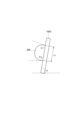
- FIG. 1 is a diagram showing an example of an advancing contact angle and a receding contact angle.
- FIG. 2 is a diagram showing an example of the advancing contact angle and the receding contact angle.
- FIG. 3 is a diagram showing an example of the advancing contact angle and the receding contact angle.
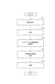
- FIG. 4 is a flowchart showing an example of the process flow of the droplet removal performance evaluation method.
- FIG. 5 is a diagram showing an example of hysteresis and a normalized value of the hysteresis.
- FIG. 6 is a diagram showing an example of the contact area and the normalized value of the contact area.
- FIG. 7 is a diagram showing an example of the droplet removal indicator.
- FIG. 1 is a diagram showing an example of an advancing contact angle and a receding contact angle.
- FIG. 2 is a diagram showing an example of the advancing contact angle and the receding contact angle.
- FIG. 3 is a diagram showing an example of the advancing
- FIG. 8 is a diagram illustrating an example of a configuration of an evaluation device.
- FIG. 9 is a diagram showing an example of the measurement results of hysteresis and contact area.
- FIG. 10 is a diagram showing an example of hysteresis and a normalized value of the hysteresis.
- FIG. 11 is a diagram illustrating an example of the contact area and the normalized value of the contact area.
- FIG. 12 is a diagram showing an example of the droplet removal indicator.
- FIG. 13 is a diagram illustrating an example of a hardware configuration of the evaluation device.
- a droplet 200 is dropped onto the surfaces of Sample 100A, Sample 100B, and Sample 100C, and the inclination angle ⁇ is increased.
- the advancing contact angle ⁇ a and receding contact angle ⁇ r at the inclination angle ⁇ just before the droplet 200 slides off are measured.
- the hysteresis is calculated as ⁇ a - ⁇ r.
- ⁇ a 100°
- ⁇ r 100°
- the hysteresis ⁇ a - ⁇ r 0°.
- ⁇ r 70°
- the hysteresis ⁇ a - ⁇ r 50°.
- the hysteresis of Sample 100A is smaller than that of Sample 100B, so it can be evaluated that Sample 100A has better droplet removal performance.
- the contact area of the droplet 200 is larger in sample 100C than in sample 100A (Lc > La). Comparing only the hysteresis, the droplet removal performance of sample 100A and sample 100C is evaluated to be the same.
- sample 100C if it is considered that the force (gravity) acting on the droplet 200 is used to increase the contact area of the droplet 200, it is considered that the force required to remove the droplet 200 is reduced in sample 100C compared to sample 100A. In other words, it is considered that sample 100C has lower droplet removal performance than sample 100A.
- Hysteresis alone does not monitor the anisotropic increase in contact area, so droplet removal performance cannot be evaluated appropriately.
- An anisotropic increase in contact area occurs when the force that attracts the droplets of the sample is greater than the force that repels them, causing the contact area to expand in the upward direction.
- the droplet removal performance of the water- and oil-repellent material was evaluated using hysteresis and the size of the contact area. Specifically, the droplet removal performance was evaluated using the following formula as a new droplet removal index.
- the normalized value of hysteresis is the value obtained by normalizing the hysteresis measured for each sample to a range from 0 to 1.
- the normalized value of the size of the contact area is the value obtained by normalizing the size of the contact area between the droplet and the sample to a range from 0 to 1.
- the size of the contact area is the contact area between the droplet and the sample, or the contact distance when the contact area between the droplet and the sample is viewed from the side.
- the normalized value of the size of the contact area may be a value obtained by normalizing the amount of change in the size of the contact area when the sample is tilted.
- step S11 the device drops a droplet onto the sample to be evaluated, and while photographing the droplet, changes the tilt angle of the sample from 0° to 90° in 1° increments.
- the droplet is photographed so that the contact angle of the droplet and the size of the contact area between the droplet and the sample can be determined.
- the tilt angle is not limited to 0° to 90°, and may be changed from any tilt angle to any other tilt angle.
- step S12 the device measures the advancing contact angle, receding contact angle, and contact area at the tilt angle before the droplet slides off. If the droplet does not slide off, the device measures the advancing contact angle, receding contact angle, and contact area when the tilt angle is 90°.
- the advancing contact angle, receding contact angle, and contact area can be measured using the image captured in step S11.
- the area of a circle whose diameter is the length of the contact area on the image may be used as the contact area.
- the length of the contact area between the droplet and the sample may be used instead of the contact area.
- the amount of change in the contact area or the amount of change in the length of the contact area may also be used. When the amount of change is used, the size of the contact area is measured without tilting the sample. In this disclosure, the contact area may be interpreted as the length of the contact area.
- steps S11 and S12 are performed for all samples.
- the processes of steps S11 and S12 may be performed multiple times for each sample to find the average of the measured values, and the average may be used as the measurement result for that sample. Droplets may also be dropped into multiple locations for each sample, measurements may be taken at each location, and the average of the measured values may be found.
- step S13 the device standardizes the hysteresis and contact area. For example, for hysteresis, 0° is set to 0, and the maximum hysteresis among each sample is set to 1, and the hysteresis of each sample is standardized. For contact area, the minimum is set to 0, and the maximum contact area among each sample is set to 1, and the contact area of each sample is standardized. When standardizing, the operator may determine the maximum value of hysteresis and the maximum value of contact area.
- Figure 5 shows an example of the hysteresis and normalized hysteresis values for samples A, B, and C.
- Hysteresis is calculated by subtracting the receding contact angle from the advancing contact angle.
- sample B's hysteresis is maximum at 50°, so for samples A, B, and C, the hysteresis from 0° to 50° is converted to 0 to 1 to normalize the hysteresis.
- Figure 6 shows an example of the contact area and normalized value of the contact area for samples A, B, and C.
- the contact area of sample C is the largest at 20, so for samples A, B, and C, the contact area of 0 to 20 is converted to 0 to 1 to normalize the contact area.
- step S14 the device substitutes the normalized hysteresis value and the normalized contact area value of each sample into the above formula to derive the droplet removal index for each sample.
- Figure 7 shows an example of the droplet removal index for sample A, sample B, and sample C.
- step S15 the device compares the droplet removal index of each sample and evaluates the droplet removal performance of each sample.
- the higher the droplet removal index obtained in step S14 the higher the droplet removal performance of the sample can be evaluated.
- sample A can be evaluated as having the highest droplet removal performance
- sample C as having the next highest droplet removal performance after sample A
- sample B as having the lowest droplet removal performance.
- the operator may determine a reference value for the droplet removal index and compare the droplet removal index of each sample with the reference value to evaluate the droplet removal performance of each sample.
- evaluation is performed using only hysteresis, the droplet removal performance of sample A and sample C are evaluated to be about the same, but by using the evaluation method of this embodiment, the difference in droplet removal performance between sample A and sample C can be more accurately evaluated.
- evaluation device An example of the configuration of an evaluation device for droplet removal performance will be described with reference to Fig. 8.
- the evaluation device 10 shown in the figure includes an input unit 11, an analysis unit 12, a calculation unit 13, and an evaluation unit 14.
- the input unit 11 inputs a still image or video of the droplet.
- the input unit 11 identifies the frame in the video where the droplet begins to slide down, and transmits the previous frame to the analysis unit 12.
- the input unit 11 may also be equipped with a camera to capture the droplet.
- the analysis unit 12 analyzes the captured image of the droplet to determine the advancing contact angle, receding contact angle, and contact area.
- the analysis unit 12 may display the image and accept input from the operator of the advancing contact angle, receding contact angle, and a line segment indicating the contact area.
- the calculation unit 13 obtains the normalized values of the hysteresis and contact area, and calculates the droplet removal index for each sample.
- the evaluation unit 14 evaluates the droplet removal performance of each sample based on the droplet removal index of each sample.
- the hysteresis and contact size were determined for droplets at three locations for each sample, and the average was calculated. The average value for each sample was used to calculate the droplet removal index.
- Figures 10 and 11 show the normalized values of the hysteresis and contact area size for each sample.
- Figure 12 shows the droplet removal index for each sample. Since sample 3 has the largest droplet removal index, the droplet removal performance of sample 3 was evaluated as high, while the droplet removal performance of samples 1 and 2 was evaluated as low.
- the advancing contact angle and receding contact angle were measured using the sliding method, but they may also be measured using the expansion/contraction method.
- the method for evaluating the droplet removal performance of this embodiment involves dropping droplets 200 onto the surfaces of samples 100A, 100B, and 100C, tilting samples 100A, 100B, and 100C after dropping droplets 200, measuring the hysteresis and the size of the contact area when samples 100A, 100B, and 100C are tilted, and evaluating the droplet removal performance of samples 100A, 100B, and 100C using the measured values of hysteresis and the size of the contact area. This allows for a more appropriate evaluation of the droplet removal performance.
- the evaluation device 10 described above can be, for example, a general-purpose computer system including a central processing unit (CPU) 901, memory 902, storage 903, communication device 904, input device 905, and output device 906, as shown in FIG. 13.
- the evaluation device 10 is realized by the CPU 901 executing a predetermined program loaded onto the memory 902.
- This program can be recorded on a non-transitory computer-readable recording medium such as a magnetic disk, optical disk, or semiconductor memory, or can be distributed via a network.
Landscapes
- Physics & Mathematics (AREA)
- Health & Medical Sciences (AREA)
- Life Sciences & Earth Sciences (AREA)
- Chemical & Material Sciences (AREA)
- Analytical Chemistry (AREA)
- Biochemistry (AREA)
- General Health & Medical Sciences (AREA)
- General Physics & Mathematics (AREA)
- Immunology (AREA)
- Pathology (AREA)
- Length Measuring Devices By Optical Means (AREA)
Priority Applications (2)
| Application Number | Priority Date | Filing Date | Title |
|---|---|---|---|
| PCT/JP2023/023305 WO2024262002A1 (ja) | 2023-06-23 | 2023-06-23 | 液滴除去性能の評価方法 |
| JP2025527379A JPWO2024262002A1 (https=) | 2023-06-23 | 2023-06-23 |
Applications Claiming Priority (1)
| Application Number | Priority Date | Filing Date | Title |
|---|---|---|---|
| PCT/JP2023/023305 WO2024262002A1 (ja) | 2023-06-23 | 2023-06-23 | 液滴除去性能の評価方法 |
Publications (1)
| Publication Number | Publication Date |
|---|---|
| WO2024262002A1 true WO2024262002A1 (ja) | 2024-12-26 |
Family
ID=93935023
Family Applications (1)
| Application Number | Title | Priority Date | Filing Date |
|---|---|---|---|
| PCT/JP2023/023305 Ceased WO2024262002A1 (ja) | 2023-06-23 | 2023-06-23 | 液滴除去性能の評価方法 |
Country Status (2)
| Country | Link |
|---|---|
| JP (1) | JPWO2024262002A1 (https=) |
| WO (1) | WO2024262002A1 (https=) |
Citations (6)
| Publication number | Priority date | Publication date | Assignee | Title |
|---|---|---|---|---|
| JPH10332547A (ja) * | 1997-06-05 | 1998-12-18 | Kdk Corp | 有機高分子材料からなる液体保持具 |
| JP2001152138A (ja) * | 1998-10-20 | 2001-06-05 | Sentan Kagaku Gijutsu Incubation Center:Kk | 滑水性膜およびその製造方法 |
| JP2006019252A (ja) * | 2004-05-31 | 2006-01-19 | Matsushita Electric Ind Co Ltd | 高分子電解質形燃料電池用セパレータ、高分子電解質形燃料電池、高分子電解質形燃料電池用セパレータの評価方法、及び、高分子電解質形燃料電池用セパレータの製造方法 |
| JP2006078477A (ja) * | 2004-08-10 | 2006-03-23 | Kanagawa Acad Of Sci & Technol | 液滴移動挙動の測定方法および装置 |
| CN110196212A (zh) * | 2019-06-12 | 2019-09-03 | 上海梭伦信息科技有限公司 | 一种基于三维空间倾斜角度修正的测度本征接触角的测试方法 |
| JP2022048876A (ja) * | 2020-09-15 | 2022-03-28 | 国立大学法人 名古屋工業大学 | 液体制御デバイス及びその利用 |
-
2023
- 2023-06-23 WO PCT/JP2023/023305 patent/WO2024262002A1/ja not_active Ceased
- 2023-06-23 JP JP2025527379A patent/JPWO2024262002A1/ja active Pending
Patent Citations (6)
| Publication number | Priority date | Publication date | Assignee | Title |
|---|---|---|---|---|
| JPH10332547A (ja) * | 1997-06-05 | 1998-12-18 | Kdk Corp | 有機高分子材料からなる液体保持具 |
| JP2001152138A (ja) * | 1998-10-20 | 2001-06-05 | Sentan Kagaku Gijutsu Incubation Center:Kk | 滑水性膜およびその製造方法 |
| JP2006019252A (ja) * | 2004-05-31 | 2006-01-19 | Matsushita Electric Ind Co Ltd | 高分子電解質形燃料電池用セパレータ、高分子電解質形燃料電池、高分子電解質形燃料電池用セパレータの評価方法、及び、高分子電解質形燃料電池用セパレータの製造方法 |
| JP2006078477A (ja) * | 2004-08-10 | 2006-03-23 | Kanagawa Acad Of Sci & Technol | 液滴移動挙動の測定方法および装置 |
| CN110196212A (zh) * | 2019-06-12 | 2019-09-03 | 上海梭伦信息科技有限公司 | 一种基于三维空间倾斜角度修正的测度本征接触角的测试方法 |
| JP2022048876A (ja) * | 2020-09-15 | 2022-03-28 | 国立大学法人 名古屋工業大学 | 液体制御デバイス及びその利用 |
Also Published As
| Publication number | Publication date |
|---|---|
| JPWO2024262002A1 (https=) | 2024-12-26 |
Similar Documents
| Publication | Publication Date | Title |
|---|---|---|
| JP6027005B2 (ja) | 顔検知及びトラッキングに基づいた連続的なオートフォーカス | |
| CN108710192B (zh) | 基于统计数据的自动对焦系统和方法 | |
| CN110753178B (zh) | 一种曝光时间调整方法及装置、摄像机 | |
| Hua et al. | Impact of out-of-focus blur on face recognition performance based on modular transfer function | |
| CN109163669A (zh) | 一种基于建筑幕墙表面的数字图像监测其面内变形的方法 | |
| CN117619676A (zh) | 一种基于在线监测的涂布量监测系统 | |
| KR20230164723A (ko) | 평가 방법, 평가 장치 및 컴퓨터 프로그램 | |
| WO2024262002A1 (ja) | 液滴除去性能の評価方法 | |
| Jiang et al. | Measuring particle size distribution using LED-illumination | |
| US11736797B2 (en) | Apparatus and method for controlling apparatus including an inclination mechanism for tilting an image sensor | |
| CN119935715A (zh) | 一种新型人机交互的视频引伸计测量系统及其方法 | |
| CN114359331B (zh) | 用于运动分割的方法和系统 | |
| JP2022539281A (ja) | 検出対象物質のスペクトル情報を抽出する方法 | |
| TWI798663B (zh) | 深度影像補償方法及其系統 | |
| KR102308974B1 (ko) | 영상정보 기반 위험체 탐지 시스템, 방법, 및 컴퓨터프로그램 | |
| TWI751184B (zh) | 產生一樣本之三維(3-d)資訊之方法及三維(3-d)量測系統 | |
| JP4574220B2 (ja) | 撮像装置及び撮像方法 | |
| KR20150138007A (ko) | 두께 판단 방법, 장치 및 시스템 | |
| JP6621435B2 (ja) | 行列長推定装置、方法、及びプログラム | |
| WO2024262003A1 (ja) | 接触角の補正方法 | |
| KR100952955B1 (ko) | 인간의 시각적 특성에 기반한 자동 노출 제어 및 초점 제어방법과 이를 이용한 비디오 카메라 시스템 | |
| CN116437203A (zh) | 一种自动聚焦方法、装置、存储介质及监控设备 | |
| KR101582735B1 (ko) | 섬모의 운동 궤적에 따른 섬모의 운동성 측정 방법 | |
| CN119413579B (zh) | 屏幕表面位移场和应变场的测量方法、装置、设备和介质 | |
| US20190349520A1 (en) | Image processing device, image processing method, image pickup apparatus, and program storage medium |
Legal Events
| Date | Code | Title | Description |
|---|---|---|---|
| 121 | Ep: the epo has been informed by wipo that ep was designated in this application |
Ref document number: 23942434 Country of ref document: EP Kind code of ref document: A1 |
|
| ENP | Entry into the national phase |
Ref document number: 2025527379 Country of ref document: JP Kind code of ref document: A |
|
| WWE | Wipo information: entry into national phase |
Ref document number: 2025527379 Country of ref document: JP |
|
| NENP | Non-entry into the national phase |
Ref country code: DE |