WO2024261813A1 - 内固定器具および治療器具 - Google Patents
内固定器具および治療器具 Download PDFInfo
- Publication number
- WO2024261813A1 WO2024261813A1 PCT/JP2023/022593 JP2023022593W WO2024261813A1 WO 2024261813 A1 WO2024261813 A1 WO 2024261813A1 JP 2023022593 W JP2023022593 W JP 2023022593W WO 2024261813 A1 WO2024261813 A1 WO 2024261813A1
- Authority
- WO
- WIPO (PCT)
- Prior art keywords
- internal fixation
- fixation device
- driver
- shaft
- tip
- Prior art date
- Legal status (The legal status is an assumption and is not a legal conclusion. Google has not performed a legal analysis and makes no representation as to the accuracy of the status listed.)
- Ceased
Links
Images
Classifications
-
- A—HUMAN NECESSITIES
- A61—MEDICAL OR VETERINARY SCIENCE; HYGIENE
- A61B—DIAGNOSIS; SURGERY; IDENTIFICATION
- A61B17/00—Surgical instruments, devices or methods
- A61B17/56—Surgical instruments or methods for treatment of bones or joints; Devices specially adapted therefor
- A61B17/58—Surgical instruments or methods for treatment of bones or joints; Devices specially adapted therefor for osteosynthesis, e.g. bone plates, screws or setting implements
- A61B17/68—Internal fixation devices, including fasteners and spinal fixators, even if a part thereof projects from the skin
- A61B17/84—Fasteners therefor or fasteners being internal fixation devices
- A61B17/86—Pins or screws or threaded wires; nuts therefor
-
- A—HUMAN NECESSITIES
- A61—MEDICAL OR VETERINARY SCIENCE; HYGIENE
- A61B—DIAGNOSIS; SURGERY; IDENTIFICATION
- A61B17/00—Surgical instruments, devices or methods
- A61B17/56—Surgical instruments or methods for treatment of bones or joints; Devices specially adapted therefor
- A61B17/58—Surgical instruments or methods for treatment of bones or joints; Devices specially adapted therefor for osteosynthesis, e.g. bone plates, screws or setting implements
- A61B17/88—Osteosynthesis instruments; Methods or means for implanting or extracting internal or external fixation devices
Definitions
- the present invention relates to a cylindrical medical internal fixation device and a treatment instrument for operating the device, and is particularly suitable for use in internal fixation surgery of the affected vertebral body.
- Vertebroplasty and spinal fixation are known as treatments for compression fractures of the spine.
- the spine consists of stacked vertebral bodies and the vertebral arch, pedicle, articular process, etc. that support them.
- the vertebral body is a cylindrical bone that sandwiches the nucleus pulposus and the annulus fibrosus that surrounds it from above and below, and is supported by two pedicles extending from the vertebral arch.
- the vertebral arches are connected above and below by the upper and lower articular processes, and support the vertebral bodies via the pedicles to form the spine.
- Compression fractures are diseases in which the vertebral body is crushed and damaged by vertical compression.
- Vertebroplasty is a surgery to reconstruct the crushed vertebral body, and a surgical procedure is used in which, for example, medical cement is filled into the vertebral body.
- Spinal fixation is a surgical procedure in which the crushed vertebral body and the healthy vertebral bodies above and below it are fixed with instruments. Screws are screwed into the crushed vertebral body and the healthy vertebral bodies above and below it from the pedicle, and the heads of the screws are connected to rods that are crossed above and below each other to fix them. If symptoms are mild, vertebroplasty is used, but if symptoms are severe, spinal fusion surgery is required.
- Patent Document 1 discloses a medical screw with a longitudinal through-hole along the central axis and a side opening that communicates with the through-hole.
- An injection device such as a syringe is attached to the head of the screw, and bone cement or a physiologically activating substance is injected from the through-hole through the opening in the rough surface into the surrounding bone, reinforcing the surrounding bone ([0053]-[0057], Figs. 6-8).
- Patent Document 2 discloses a medical screw that can be easily removed from the fracture site into which it has been screwed.
- the medical screw has a hollow section formed from the head to the tip along the central axis, with a screw thread formed on the side, and is screwed into the bone.
- a reverse thread (reverse internal thread) is provided near the inside tip of the hollow section of the screw, and it can be removed by using a removal tool with a tip that engages with the reverse internal thread. More specifically, the removal tool is inserted from the hollow section and its tip is meshed and integrated with the reverse internal thread of the screw, and the removal tool is then rotated to remove the screw from the body.
- This invention is a treatment instrument integrated with a screw having a through hole along the central axis and a tappable thread on the side, and is configured so that, with a driver connected to the head of the screw, bone cement can be injected into the affected area through the through hole of the screw, and then the screw can be screwed into the bone cement. After injecting the bone cement, there is no need to attach the driver again, and the driver can be operated as is, so the screw can be screwed in quickly before the bone cement hardens.
- the removal tool described in Patent Document 2 can strongly connect the screw and the driver and transmit a strong force to the screw, which helps removal when the surrounding area is diseased tissue such as the patient's bone, but when the bond between the bone cement and the screw is stronger than the adhesion between the bone cement and the surrounding diseased tissue such as the bone, as described above, there is a risk that the bone cement will separate from the surrounding diseased tissue instead of the screw coming out of the bone cement, and it does not help removal.
- the objective of the present invention is to provide an internal fixation device that is inserted from the pedicle into bone cement that has already been filled into the vertebral body, and that can be easily removed while maintaining the same level of internal fixation performance as a screw.
- it is an internal fixation device that is inserted from the pedicle into the bone cement filled in the vertebral body, and has a cylindrical shaft and a connection part at the distal end of the shaft that can be connected to a driver, and the shaft has a spiral groove on the proximal side.
- Bone cement is a medical cement that contains calcium phosphate and polymethylmethacrylate as its main ingredients, and hardens over time.
- an internal fixation device that is inserted from the pedicle into bone cement that has already been filled into the vertebral body, and that can be easily removed while maintaining the same level of internal fixation performance as a screw.
- FIG. 1 is a top view, a front view, and a bottom view showing a configuration example of an internal fixation device of the present invention.
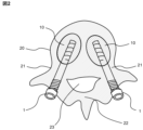
- FIG. 2 is an explanatory diagram showing an example of use of the internal fixation device of the present invention from a bird's-eye view.
- FIG. 3 is an explanatory diagram showing the solution principle of the present invention.
- FIG. 4 is an explanatory diagram showing an example of how to use the internal fixation device of the present invention in a step-by-step manner.
- FIG. 5 is an explanatory diagram that shows a schematic cross-sectional structure to illustrate a configuration example of a treatment device according to a second embodiment of the present invention.
- FIG. 1 is a top view, a front view, and a bottom view showing a configuration example of an internal fixation device of the present invention.
- FIG. 2 is an explanatory diagram showing an example of use of the internal fixation device of the present invention from a bird's-eye view.
- FIG. 3 is an explanatory
- FIG. 6 is an explanatory diagram showing an example of the configuration of the tip end of the inner cylinder from a bird's-eye view.
- FIG. 7 is an explanatory diagram showing a schematic cross-sectional structure to show an example of the configuration of the tip portion of the inner cylinder.
- FIG. 8 is an explanatory diagram that shows a schematic diagram of a treatment procedure (first half) using the treatment device of the present invention.
- FIG. 9 is an explanatory diagram that shows a schematic diagram of a treatment procedure (latter half) using the treatment device of the present invention.
- the groove is deeper on the tip side.
- the groove is deeper on the proximal side of the shaft than on the distal side.
- the shaft is tapered toward the tip.
- the shaft has a tapered portion (7) at the proximal end whose diameter gradually decreases from the center.
- the shaft has the groove on the proximal side and a convex thread (5) on the distal side.
- the groove has fewer threads than the thread.
- the number of threads in the groove is smaller than the number of threads in the thread.
- Treatment instrument for operating the internal fixation instrument of the present invention (Figs. 5, 6, and 7)
- a representative embodiment disclosed in the present application is a treatment instrument (100) including a cylindrical driver (40) connectable to an internal fixation instrument (1) that is inserted from the pedicle into bone cement filled in a vertebral body, and an inner cylinder (30) that can be inserted into the driver, and is configured as follows.
- the internal fixation device has a cylindrical shaft (2) and a connection part (3) at the distal end of the shaft that can be connected to the driver, and has a through hole (6) that allows the inner cylinder to pass along the central axis from the distal end to the proximal end.
- the shaft has a spiral groove (4) on the proximal side.
- the driver has a through hole that allows the inner tube to pass from the head to the tip along the central axis, and can be moved along the central axis to fit into the connection part (3) of the internal fixed device and be connected to the internal fixed device, and can transmit a rotational force around the central axis to the internal fixed device.
- the inner tube has a connection portion (35) that is inserted into the through hole of the driver from the distal end and is connected to the driver at the distal end, and a tip portion (32) that protrudes proximally beyond the tip of the internal fixation device connected to the driver, and has an elastic tongue (31) with a protrusion (33) at its tip.
- the tongue bends toward the central axis and can move in the central axis direction within the through-holes of the driver and the internal fixing device. Also, when the inner tube is inserted into the through-hole of the driver and connected to the driver at the distal end and further connected to the internal fixing device, the convex portion comes into contact with the tip of the internal fixing device.
- This provides a treatment instrument (100) suitable for inserting the internal fixation instrument (1) of [1] to [6] from the pedicle into the bone cement filled in the vertebral body.
- the driver (40) with the inner tube (30) inserted therein is connected to the internal fixation instrument (1), they are integrated.
- This integration is achieved by connecting the driver (40) and the internal fixation instrument (1) at the connection part (3) of the internal fixation instrument, and by connecting the inner tube to the distal end of the driver and contacting and holding the protruding part of the tongue against the tip of the internal fixation instrument.
- the inner tube has a through hole through which a guide pin (15, not shown in Figures 5 to 7) can pass from the distal end to the proximal end along the central axis, and when the inner tube is inserted into the through hole of a driver (40) and connected to the driver at its distal end and also connected to the internal fixation instrument (1), the guide pin is further inserted into the inner tube, thereby restricting the multiple tongues from bending in the direction of the central axis, and bringing the convex portion into contact with the tip of the internal fixation instrument, thereby restricting the movement of the inner tube back along the central axis toward the through hole of the internal fixation instrument.
- a guide pin 15, not shown in Figures 5 to 7
- the integrated treatment instrument (100) described in [7] when operated to insert the internal fixation instrument (1) from the pedicle into the vertebral body, the internal fixation instrument can be smoothly delivered to the vertebral body even if the diameter of the bone hole formed in the pedicle is small.
- the proximal end of the internal fixation device is blunt.
- the proximal end of the internal fixation device is blunt.
- the internal fixation device has a groove on the proximal side and a thread on the distal side.
- the shaft of the internal fixation device has the groove on the proximal side and a convex thread (5) on the distal side.
- this allows the bone cement to smoothly enter the groove (4) when the internal fixation device (1) is screwed in, providing a strong fixation, while at the same time reducing the force required for removal by applying a rotation in the opposite direction to that used when screwing in.
- the groove has fewer threads than the thread.
- the number of grooves of the internal fixation device is smaller than the number of threads of the thread.
- the bonding strength between the internal fixation device (1) and the bone cement can be appropriately designed while strengthening the fixation with the pedicle by the screw threads (5).
- FIG. 1A, 1B and 1C are a top view, a front view and a bottom view showing an example of the configuration of an internal fixation device of the present invention.
- the back view and the left and right side views are omitted because they are the same as the front view (b) except that the groove 4 and the thread 5 are arranged at positions extended from the front view (b).
- the internal fixation device 1 comprises a cylindrical shaft 2 and a connection part 3 at the distal end of the shaft 2 that can be connected to a driver, and the shaft 2 has a spiral groove 4 on the proximal side.
- the shaft 2 is preferably cylindrical and has a through hole 6 that penetrates from the distal end to the proximal end along the central axis.
- the through hole 6 can be configured to allow a guide pin to pass through.
- the through hole 6 may also be configured to allow a bone drilling tool, balloon catheter, bone cement injector, etc. to pass through.
- the connection part 3 is configured as a hexagonal column-shaped recess to engage with, for example, a hexagonal wrench as shown in the figure so that the entire internal fixation device 1 can be rotated by engaging with a driver (not shown).
- FIG 2 is an explanatory diagram showing an example of using the internal fixation device 1 from above.
- the spine is composed of multiple vertebral bodies 20 stacked one on top of the other, and Figure 2 shows one of these vertebral bodies as seen through from above and below.
- the vertebral bodies 20 are supported by a pair of left and right pedicles 21, which are connected by a vertebral arch 22.
- the area surrounded by the vertebral bodies 20, pedicles 21, and vertebral arch 22 is the spinal canal 23.
- a compression fracture is a disease in which a vertebral body is compressed and crushed by a force in the vertical direction.
- the space is returned to the vertebral body 20 and bone cement 10 is injected, and the internal fixation device 1 is inserted (screwed in) before it hardens, providing support from the pedicle 21 side.
- the internal fixation device 1 is inserted from the pedicle 21 into the bone cement 10 that has been filled in the vertebral body 20 beforehand, and when the bone cement 10 hardens, it is supported by the internal fixation device 1 from the pedicle 21 and fixed into the vertebral body 20.
- FIG. 3 is an explanatory diagram showing the solution principle of the present invention.
- the upper side (a) shows a cross section of the joining of bone cement 10 and shaft 2 having groove 4, and the lower side (b) shows a cross section of the joining when it is assumed that shaft 2 has a thread instead of groove 4. Since it is different from the thread 5 on the distal side of shaft 2, the reference number 5 is not added.
- groove 4 is recessed in the central axis direction from the outer circumferential surface of shaft 2, and the thread is convex outward from the outer circumferential surface of shaft 2.
- shaft 2 has thread (b)
- the thread taps bone cement 10, that is, the thread advances while pushing out the bone cement 10 around the protruding part, so that the surface of the thread is in close contact with bone cement 10.
- a propulsive force is also applied from the rotational force of tapping.
- the shaft 2 has a groove 4 (a)
- the groove 4 does not have the effect of tapping the bone cement 10, so the bone cement 10 penetrates into the groove 4 solely due to the viscosity of the bone cement 10.
- the bone cement 10 does not necessarily reach the bottom of the groove 4, and a gap may remain as illustrated in the figure.
- the action of the thread and the groove on the bone cement is completely different, and as a result, the degree of adhesion also differs greatly.
- the groove 4 By forming the groove 4 on the shaft 2, it becomes easier to remove compared to when a thread is formed, but it can be made more difficult to remove compared to when only the shaft 2 is formed. Therefore, by appropriately adjusting the length, number, and depth of the groove 4, it is possible to achieve an appropriate ease of removal.
- groove 4 shown in the figure is a triangle with a pointed bottom
- its shape can be arbitrary, and the angle of the bottom can be arbitrary, being more acute or obtuse than the right angle shown in the example, and the bottom can also be flat or arc-shaped.
- the thread used for comparison has a sharp tip, the above-mentioned solution principle would be the same even if the corners were smoothly chamfered.
- the depth of the groove 4 of the internal fixation device 1 may be uniform, but it is more preferable to make the proximal side (tip side) of the shaft 2 deeper than the distal side (head side).
- the proximal side (tip side) that comes into contact with the bone cement 10 is deeper first, so the bone cement 10 penetrates deeper into the groove 4, and as it is screwed in, it is sent along the spiral of the groove 4 to the shallower distal side (head side) of the groove 4, so the bone cement 10 smoothly penetrates into the groove 4 and is firmly fixed.
- removing the internal fixation device 1 it rotates in the opposite direction along the spiral of the groove 4 while being separated from the bone cement 10, so the force required for removal can be reduced.
- the shaft 2 of the internal fixation device 1 has a tapered section 7 whose diameter gradually decreases from the center toward the proximal end.
- the distal side (head side) of the shaft 2 of the internal fixation device 1 may be provided with a screw thread 5.
- the screw thread 5 is a helical convex portion that protrudes outward from the outer circumferential surface of the shaft 2, and has the function of advancing the internal fixation device 1 (shaft 2) along the central axis by tapping the surrounding bone as it rotates. As shown in FIG. 2, the screw thread 5 advances by tapping the pedicle 21, firmly fixing the internal fixation device 1 and stably supporting the bone cement 10 in the vertebral body 20 into which the shaft 2 is inserted.
- the thread 5 and groove 4 are preferably formed with equal leads.
- the lead is the distance traveled along the central axis relative to the amount of rotation of the shaft 2, so it is desirable that the distance traveled by the thread 5 tapping the pedicle 21 while advancing the shaft 2 is equal to the distance traveled by the shaft 2 along the spiral of the groove 4 when screwed into the bone cement 10.
- the number of threads can be different between the groove 4 and the thread 5.
- the number of threads in the groove 4 can be smaller than the number of threads in the thread 5. This allows the bonding force between the internal fixation device 1 and the bone cement 10 to be appropriately designed while strengthening the fixation to the pedicle 21 by the thread 5.
- the fixation of the internal fixation device 1 to the pedicle 21 can be strengthened.
- the relationship between the bone cement 10 and the groove 4 and the relationship between the pedicle 21 and the thread 5 can be independently optimized.
- Figure 4 is an explanatory diagram showing a procedure for an example of using the internal fixation device 1 of the present invention.
- the spine is composed of multiple vertebral bodies 20 stacked one on top of the other when the patient is in a standing position, and the vertebral bodies 20 are supported by a pair of left and right pedicles 21, which are connected by a vertebral arch 22.
- Figure 4 shows a cross section from the patient's body surface (not shown) through one pedicle 21 to the vertebral body 20, with the body surface at the top.
- Step A The skin on the side that allows access to the affected vertebral body 20 is incised, and a bone hole 19 is formed in the pedicle 21 that reaches the vertebral body 20.
- the diameter of the bone hole 19 may be a size that allows just the shaft 2 of the internal fixation device 1 to be inserted, or a bone hole that allows the guide pin described below to be inserted, and the length is approximately long enough to reach the vertebral body 20.
- Step B Insert the shaft 2 of the internal fixation device 1 into the created bone hole 19.
- a guide pin (not shown) may be inserted from outside the body through the bone hole 19 into the vertebral body 20, and the internal fixation device 1 may be inserted along the guide pin.
- the part of the shaft 2 without any protrusions such as the thread 5 is inserted into the bone hole 19, and the part with the thread 5 may stop outside the pedicle 21.
- a balloon catheter 12 is inserted into the through hole 6 of the shaft 2 of the internal fixation device 1, and its tip is brought into the vertebral body 20, and the balloon 11 at the tip is inflated to secure space inside the vertebral body 20.
- a driver 14 (not shown) may be connected to the connection part of the head 3 of the internal fixation device 1, and the thread 5 may be slightly screwed into the pedicle 21 in advance.
- a drilling needle or a bone excavator may be introduced into the vertebral body 20 from outside the body through the bone hole 19 to excavate the bone from inside the vertebral body 20. It is more preferable that the tip of the internal fixation device 1 is smoothly chamfered.
- step B in which the balloon 11 is introduced into the vertebral body 20 through the through hole 6 of the internal fixation device 1, inflated, and then removed, the risk of the balloon 11 touching and damaging the tip of the internal fixation device 1 can be reduced.
- Step C Insert a cement injector 13 instead of the balloon catheter 12 into the through hole 6 of the shaft 2 of the internal fixation device 1, bring the tip of the cement injector 13 into the vertebral body 20, and inject bone cement 10 from the tip of the cement injector 13 into the vertebral body 20.
- a driver 14 (not shown in [c]) may be connected in advance to the connection part of the head 3 of the internal fixation device 1, and the cement injector 13 may be configured to be introduced to the affected vertebral body 20 through a through hole that is provided along the central axis of the driver 14 as described above and communicates with the through hole 6 of the connected internal fixation device 1.
- Step D The driver 14 is connected to the connection part of the head 3 of the internal fixation device 1, and the screw thread 5 is screwed into the pedicle 21. At this time, the tip (proximal end) of the internal fixation device 1, the part of the shaft 2 where the groove 4 is formed, is screwed into the bone cement 10.
- the driver 14 is removed from the internal fixation device 1, the opening is sutured, and the surgery is completed.
- the driver 14 is not shown in [B] and [C], but as described above, it is preferable to provide a through hole in the driver 14 that communicates with the through hole 6 of the internal fixation device 1, and to configure so that steps B and C can be carried out with the driver 14 attached to the internal fixation device 1 from the beginning of step B.
- a drill needle, a bone excavator (not shown), a balloon catheter 12, and a cement injector 13 can be sequentially introduced into the vertebral body 20 through the through hole that communicates from the driver 14 to the internal fixation device 1, and the excavation of the bone in the vertebral body 20, the expansion of the space with a balloon, and the filling of the bone cement 10 can be performed with the driver 14 attached from the beginning.
- the internal fixation device 1 of the present invention is more preferably used in combination with the treatment device 100 according to the above-mentioned international patent application (PCT/JP2022/036147).
- FIG. 5 is an explanatory diagram showing the present embodiment 2 as an example of one use of the internal fixation device 1. Note that FIG. 5 is drawn with the scale in the central axis direction (vertical direction on the page) compressed and with emphasis on the direction along the patient's body surface (horizontal direction on the page).
- the treatment device 100 includes a cylindrical driver 40 that can screw the internal fixation device 1 into the pedicle 21, and an inner tube 30 that is inserted into the driver 40, and is configured as follows.
- the tip of the internal fixation device 1 is blunt so that a soft vertebral excavation device such as a balloon can be inserted and removed, and the through hole 6 has a diameter that allows the inner tube 30 to pass along the central axis from the head 3 to the tip.
- the driver 40 is configured to be fitted into the connection part of the head 3 of the internal fixation device 1 by moving it along the central axis, and to be connected to the internal fixation device 1, so that a force in the rotational direction around the central axis can be transmitted to the internal fixation device 1.
- the tip of the driver 40 may be formed in the shape of a hexagonal wrench (hexagonal column), and the connection part of the head 3 of the internal fixation device 1 may be formed with a hexagonal groove (recess).
- the shape of the tip of the driver 40 and the shape of the connection part of the head 3 of the internal fixation device 1 may be other than hexagonal, such as a star shape, as long as they fit together simply by being inserted.
- the tip of the driver 40 fits into the connection part of the head 3 of the internal fixation device 1, making it possible to screw the internal fixation device 1 with the driver 40, and by pulling out the driver 40, it can be easily removed.
- the inner tube 30 is inserted from the distal end of the driver 40 through the through holes of the driver 40 and the internal fixation device 1, and has a tip portion 32 that protrudes proximally beyond the tip of the internal fixation device 1.
- the inner tube 30 is integrally connected to the driver 40 and the internal fixation device 1 with the tip portion 32 protruding proximally beyond the tip of the internal fixation device 1.
- the driver 40 and the inner tube 30 are configured so that they can be connected at their distal ends.
- the distal end of the driver 40 is provided with a cylindrical connection part 45 having a male screw 46 thread on the outer circumferential surface, and the distal end of the inner tube 30 is provided with a groove-shaped connection part 35 that can accommodate the cylinder, and a female screw 36 that engages with the male screw 46 is formed.
- the relationship of the convex and concave parts and the relationship of the male screw and the female screw may be reversed, or other connection mechanisms may be used.
- the driver 40 is provided with a handle 47 and the inner tube 30 is provided with a handle 37, and it is preferable that they are integrated so that they are easy to grip when connected. Even if the connection is made with a screw as in this example, a latch mechanism (not shown) may be further provided to prevent the connection from coming loose.
- the tip (proximal end) of the inner tube 30 is divided into multiple tongues 31 in the direction along the central axis, and each of the multiple tongues 31 has a protrusion 33 in the direction away from the central axis.
- the protrusion 33 has a notch function to prevent the internal fixation device 1 from slipping out of the inner tube 30 as described below, so the symbol 33 is referred to as a notch.
- the multiple tongues 31 are formed, for example, by dividing the cylindrical inner tube 30 from the tip side with slits. The number of divisions is arbitrary, for example, four, six, two, three, etc.
- some processing for example, heat treatment, processing to reduce the thickness, processing to bond a metal with high elasticity
- the elasticity of the tongues 31 is designed to have appropriate bending. For example, when the inner tube 30 passes through the through hole of the driver 40, the notch 33 is pressed against the inner wall of the through hole, bending in the direction of the central axis to allow the inner tube 30 to pass, and when the notch 33 comes out proximal to the tip of the internal fixation device 1, the bending returns to its original state and the notch 33 catches on the tip of the internal fixation device 1.
- the notch 33 has a smooth shape, even after the notch 33 comes out from the tip of the internal fixation device 1, the force to pull the inner tube 30 out can be used to pull the notch 33 into the through hole 6 of the internal fixation device 1, and the tongue piece 31 can be bent again in the direction of the central axis, allowing the inner tube 30 to be pulled out.
- FIG. 7 is an explanatory diagram showing a schematic cross-sectional structure to show an example of the configuration of the tip portion 32 of the inner tube 30.
- the above-mentioned tongue piece 31 bends toward the central axis and can move in the central axis direction within the through hole.
- the tip 32 of the inner tube 30 has a thread 34 that can be tapped onto the outer circumferential surface.
- the thread 34 should be formed in a position that smoothly connects with the inclined portion of the internal fixation device 1 when the internal fixation device 1, the driver 40, and the inner tube 30 are integrated as described above.
- This section describes treatment methods for spinal diseases using the treatment device 100 of the present invention, including artificial disc replacement, spinal fixation, vertebroplasty, and pedicle plasty.
- FIGS. 8 and 9 are explanatory diagrams that show a typical procedure for treatment using the treatment device 100 of the second embodiment, with FIG. 8 showing the first half of the procedure and FIG. 9 showing the second half.
- FIGS. 8 and 9 show vertebroplasty, the method of inserting the internal fixation device 1 into the vertebral body is similar to that of spinal fixation and vertebral body reinforcement surgery in artificial disc replacement (not shown).
- FIGS. 8 and 9 show a typical cross section of the affected area of a patient, with the upper side of the page being the distal side and the lower side being the proximal side, from the outside of the skin 24 through the pedicle 21 to the vertebral body 20.
- the scale of the central axis direction (vertical direction on the page) is compressed, and the direction along the patient's body surface (horizontal direction on the page) is emphasized.
- the pedicle 21 is located on both the left and right sides of the vertebral body 20, so the same treatment is performed on one vertebral body 20 from both the left and right, but FIGS. 8 and 9 show one side of the treatment.
- a vertebral body excavation device may be introduced through the driver 40 and the through-hole of the internal fixation device 1 to excavate the inside of the vertebral body 20 in order to fill the vertebral body with cement for reinforcement.
- the balloon 11 is inflated by injecting a contrast agent through the balloon catheter 12 and applying pressure.
- the purpose is to return the vertebral body 20 to its original size when the vertebral body 20 has a compression fracture due to osteoporosis or the like.
- the treatment device 100 allows the internal fixation device 1 to be screwed into the filled bone cement 10 immediately after the bone cement 10 is filled, making it suitable for procedures such as spinal fixation surgery, vertebral reinforcement surgery in artificial disc replacement surgery, vertebroplasty, and pedicle formation.
- the filled bone cement 10 is soft enough that the internal fixation device 1 can be screwed in without tapping using the threads 34 on the tip 32 of the inner tube 30. Similarly, the internal fixation device 1 can be screwed into the pedicle 21 without tapping using the tip 32 of the inner tube 30.
- the treatment instrument 100 is also suitable for removing the internal fixation instrument 1. After incising the affected area and drilling a hole up to the head of the screw, the guide pin 15 is inserted into the internal fixation instrument 1, and the driver 40 is introduced along it to the internal fixation instrument 1, and the driver 40 can be connected simply by pushing in the tip. The internal fixation instrument 1 can then be removed by rotating the driver 40.
- the present invention relates to a cylindrical internal fixation device for medical use, and is particularly suitable for use in internal fixation surgery of the affected vertebral body.
Landscapes
- Health & Medical Sciences (AREA)
- Orthopedic Medicine & Surgery (AREA)
- Life Sciences & Earth Sciences (AREA)
- Surgery (AREA)
- Medical Informatics (AREA)
- Engineering & Computer Science (AREA)
- Biomedical Technology (AREA)
- Heart & Thoracic Surgery (AREA)
- Nuclear Medicine, Radiotherapy & Molecular Imaging (AREA)
- Molecular Biology (AREA)
- Animal Behavior & Ethology (AREA)
- General Health & Medical Sciences (AREA)
- Public Health (AREA)
- Veterinary Medicine (AREA)
- Neurology (AREA)
- Surgical Instruments (AREA)
Priority Applications (5)
| Application Number | Priority Date | Filing Date | Title |
|---|---|---|---|
| CN202380097418.6A CN121218942A (zh) | 2023-06-19 | 2023-06-19 | 内固定器具以及治疗器具 |
| JP2025527225A JP7847393B2 (ja) | 2023-06-19 | 2023-06-19 | 内固定器具および治療器具 |
| PCT/JP2023/022593 WO2024261813A1 (ja) | 2023-06-19 | 2023-06-19 | 内固定器具および治療器具 |
| EP23942252.0A EP4729007A1 (en) | 2023-06-19 | 2023-06-19 | Internal fixation instrument and treatment instrument |
| TW113121579A TW202500099A (zh) | 2023-06-19 | 2024-06-12 | 內固定器具以及治療器具 |
Applications Claiming Priority (1)
| Application Number | Priority Date | Filing Date | Title |
|---|---|---|---|
| PCT/JP2023/022593 WO2024261813A1 (ja) | 2023-06-19 | 2023-06-19 | 内固定器具および治療器具 |
Publications (1)
| Publication Number | Publication Date |
|---|---|
| WO2024261813A1 true WO2024261813A1 (ja) | 2024-12-26 |
Family
ID=93935158
Family Applications (1)
| Application Number | Title | Priority Date | Filing Date |
|---|---|---|---|
| PCT/JP2023/022593 Ceased WO2024261813A1 (ja) | 2023-06-19 | 2023-06-19 | 内固定器具および治療器具 |
Country Status (5)
| Country | Link |
|---|---|
| EP (1) | EP4729007A1 (https=) |
| JP (1) | JP7847393B2 (https=) |
| CN (1) | CN121218942A (https=) |
| TW (1) | TW202500099A (https=) |
| WO (1) | WO2024261813A1 (https=) |
Citations (7)
| Publication number | Priority date | Publication date | Assignee | Title |
|---|---|---|---|---|
| US20040068269A1 (en) * | 2002-10-07 | 2004-04-08 | Bonati Alfred O. | Clamping screw extractor |
| US6997086B1 (en) * | 2005-09-02 | 2006-02-14 | Neil John Graham | Locking screwdriver |
| US20110040337A1 (en) | 2007-11-13 | 2011-02-17 | Piero Budassi | Screw for stabilizing a bone fracture and related kit |
| US20120046698A1 (en) * | 2010-08-18 | 2012-02-23 | Doctors Research Group, Inc. | Methods and devices for spinal fusion |
| JP2016515857A (ja) * | 2013-03-15 | 2016-06-02 | インノビシオン, インコーポレーティッド | 骨ねじ及びその使用方法 |
| JP2016209295A (ja) | 2015-05-08 | 2016-12-15 | 多摩メディカル有限会社 | 医療用スクリュー及び該スクリューの抜去操作治具 |
| JP2017533759A (ja) * | 2014-11-04 | 2017-11-16 | ハイプリヴェンション | 骨折骨または非骨折骨を安定させるためのインプラント |
Family Cites Families (2)
| Publication number | Priority date | Publication date | Assignee | Title |
|---|---|---|---|---|
| EP3524181B1 (en) * | 2018-02-09 | 2021-11-10 | Biedermann Technologies GmbH & Co. KG | System of a bone anchor and an elongate instrument |
| JP7300133B1 (ja) * | 2022-09-28 | 2023-06-29 | 株式会社スパインクロニクルジャパン | 治療器具およびスクリュー |
-
2023
- 2023-06-19 WO PCT/JP2023/022593 patent/WO2024261813A1/ja not_active Ceased
- 2023-06-19 JP JP2025527225A patent/JP7847393B2/ja active Active
- 2023-06-19 CN CN202380097418.6A patent/CN121218942A/zh active Pending
- 2023-06-19 EP EP23942252.0A patent/EP4729007A1/en active Pending
-
2024
- 2024-06-12 TW TW113121579A patent/TW202500099A/zh unknown
Patent Citations (7)
| Publication number | Priority date | Publication date | Assignee | Title |
|---|---|---|---|---|
| US20040068269A1 (en) * | 2002-10-07 | 2004-04-08 | Bonati Alfred O. | Clamping screw extractor |
| US6997086B1 (en) * | 2005-09-02 | 2006-02-14 | Neil John Graham | Locking screwdriver |
| US20110040337A1 (en) | 2007-11-13 | 2011-02-17 | Piero Budassi | Screw for stabilizing a bone fracture and related kit |
| US20120046698A1 (en) * | 2010-08-18 | 2012-02-23 | Doctors Research Group, Inc. | Methods and devices for spinal fusion |
| JP2016515857A (ja) * | 2013-03-15 | 2016-06-02 | インノビシオン, インコーポレーティッド | 骨ねじ及びその使用方法 |
| JP2017533759A (ja) * | 2014-11-04 | 2017-11-16 | ハイプリヴェンション | 骨折骨または非骨折骨を安定させるためのインプラント |
| JP2016209295A (ja) | 2015-05-08 | 2016-12-15 | 多摩メディカル有限会社 | 医療用スクリュー及び該スクリューの抜去操作治具 |
Non-Patent Citations (1)
| Title |
|---|
| See also references of EP4729007A1 |
Also Published As
| Publication number | Publication date |
|---|---|
| JPWO2024261813A1 (https=) | 2024-12-26 |
| JP7847393B2 (ja) | 2026-04-17 |
| EP4729007A1 (en) | 2026-04-22 |
| TW202500099A (zh) | 2025-01-01 |
| CN121218942A (zh) | 2025-12-26 |
Similar Documents
| Publication | Publication Date | Title |
|---|---|---|
| JP5653908B2 (ja) | 後脊椎固定具 | |
| US7963967B1 (en) | Bone preparation tool | |
| JP7300133B1 (ja) | 治療器具およびスクリュー | |
| CN101720207A (zh) | 用于将矫正材料传递到骨头中的装置、系统和方法 | |
| JP2007511324A (ja) | 有窓ボーンタップおよび方法 | |
| JP2013078599A (ja) | 骨に補強材を配送する装置および方法 | |
| US20090264941A1 (en) | Guide sleeve for accessing a vertebral body and related methods of use | |
| AU2007349003B2 (en) | Method and kit for intra osseous navigation and augmentation of bone | |
| JP2018020153A (ja) | 骨−軟骨間刺激による軟骨修復、保存および成長ならびにそのための送達系および関連する方法 | |
| KR20210011635A (ko) | 경피적 척추 성형술용 본시멘트 주입장치 | |
| US20090005816A1 (en) | Spinal rod, insertion device, and method of using | |
| CN216136002U (zh) | 一种骨水泥髓内钉固定系统 | |
| KR200409151Y1 (ko) | 척추뼈 수술용 나선 파이프 | |
| WO2024261813A1 (ja) | 内固定器具および治療器具 | |
| WO2025017834A1 (ja) | 治療器具 | |
| WO2025169259A1 (ja) | 治療器具 | |
| CN114305608B (zh) | 一种成角穿刺器及其经皮经单侧椎弓根的椎体融合系统 | |
| KR200397033Y1 (ko) | 척추뼈 질환용 성형기구 | |
| KR200361374Y1 (ko) | 나선형 척추뼈 질환용 성형기구 | |
| WO2026009303A1 (ja) | 治療器具 | |
| TW202612659A (zh) | 治療器具 | |
| EP4721683A1 (en) | Treatment instrument | |
| WO2026078987A1 (ja) | 治療器具 | |
| TW202612656A (zh) | 治療器具 |
Legal Events
| Date | Code | Title | Description |
|---|---|---|---|
| 121 | Ep: the epo has been informed by wipo that ep was designated in this application |
Ref document number: 23942252 Country of ref document: EP Kind code of ref document: A1 |
|
| WWE | Wipo information: entry into national phase |
Ref document number: 2025527225 Country of ref document: JP |
|
| ENP | Entry into the national phase |
Ref document number: 2023942252 Country of ref document: EP Effective date: 20260119 |
|
| WWE | Wipo information: entry into national phase |
Ref document number: 2023942252 Country of ref document: EP |
|
| NENP | Non-entry into the national phase |
Ref country code: DE |
|
| ENP | Entry into the national phase |
Ref document number: 2023942252 Country of ref document: EP Effective date: 20260119 |
|
| ENP | Entry into the national phase |
Ref document number: 2023942252 Country of ref document: EP Effective date: 20260119 |
|
| ENP | Entry into the national phase |
Ref document number: 2023942252 Country of ref document: EP Effective date: 20260119 |
|
| WWP | Wipo information: published in national office |
Ref document number: 2023942252 Country of ref document: EP |