EP3524181B1 - System of a bone anchor and an elongate instrument - Google Patents
System of a bone anchor and an elongate instrument Download PDFInfo
- Publication number
- EP3524181B1 EP3524181B1 EP18156123.4A EP18156123A EP3524181B1 EP 3524181 B1 EP3524181 B1 EP 3524181B1 EP 18156123 A EP18156123 A EP 18156123A EP 3524181 B1 EP3524181 B1 EP 3524181B1
- Authority
- EP
- European Patent Office
- Prior art keywords
- bone anchor
- elongate instrument
- channel
- tip portion
- bone
- Prior art date
- Legal status (The legal status is an assumption and is not a legal conclusion. Google has not performed a legal analysis and makes no representation as to the accuracy of the status listed.)
- Active
Links
Images


Classifications
-
- A—HUMAN NECESSITIES
- A61—MEDICAL OR VETERINARY SCIENCE; HYGIENE
- A61B—DIAGNOSIS; SURGERY; IDENTIFICATION
- A61B17/00—Surgical instruments, devices or methods, e.g. tourniquets
- A61B17/56—Surgical instruments or methods for treatment of bones or joints; Devices specially adapted therefor
- A61B17/58—Surgical instruments or methods for treatment of bones or joints; Devices specially adapted therefor for osteosynthesis, e.g. bone plates, screws, setting implements or the like
- A61B17/68—Internal fixation devices, including fasteners and spinal fixators, even if a part thereof projects from the skin
- A61B17/84—Fasteners therefor or fasteners being internal fixation devices
- A61B17/86—Pins or screws or threaded wires; nuts therefor
- A61B17/864—Pins or screws or threaded wires; nuts therefor hollow, e.g. with socket or cannulated
-
- A—HUMAN NECESSITIES
- A61—MEDICAL OR VETERINARY SCIENCE; HYGIENE
- A61B—DIAGNOSIS; SURGERY; IDENTIFICATION
- A61B17/00—Surgical instruments, devices or methods, e.g. tourniquets
- A61B17/16—Bone cutting, breaking or removal means other than saws, e.g. Osteoclasts; Drills or chisels for bones; Trepans
- A61B17/1613—Component parts
- A61B17/1615—Drill bits, i.e. rotating tools extending from a handpiece to contact the worked material
-
- A—HUMAN NECESSITIES
- A61—MEDICAL OR VETERINARY SCIENCE; HYGIENE
- A61B—DIAGNOSIS; SURGERY; IDENTIFICATION
- A61B17/00—Surgical instruments, devices or methods, e.g. tourniquets
- A61B17/16—Bone cutting, breaking or removal means other than saws, e.g. Osteoclasts; Drills or chisels for bones; Trepans
- A61B17/1655—Bone cutting, breaking or removal means other than saws, e.g. Osteoclasts; Drills or chisels for bones; Trepans for tapping
-
- A—HUMAN NECESSITIES
- A61—MEDICAL OR VETERINARY SCIENCE; HYGIENE
- A61B—DIAGNOSIS; SURGERY; IDENTIFICATION
- A61B17/00—Surgical instruments, devices or methods, e.g. tourniquets
- A61B17/16—Bone cutting, breaking or removal means other than saws, e.g. Osteoclasts; Drills or chisels for bones; Trepans
- A61B17/1662—Bone cutting, breaking or removal means other than saws, e.g. Osteoclasts; Drills or chisels for bones; Trepans for particular parts of the body
- A61B17/1671—Bone cutting, breaking or removal means other than saws, e.g. Osteoclasts; Drills or chisels for bones; Trepans for particular parts of the body for the spine
-
- A—HUMAN NECESSITIES
- A61—MEDICAL OR VETERINARY SCIENCE; HYGIENE
- A61B—DIAGNOSIS; SURGERY; IDENTIFICATION
- A61B17/00—Surgical instruments, devices or methods, e.g. tourniquets
- A61B17/16—Bone cutting, breaking or removal means other than saws, e.g. Osteoclasts; Drills or chisels for bones; Trepans
- A61B17/17—Guides or aligning means for drills, mills, pins or wires
- A61B17/1725—Guides or aligning means for drills, mills, pins or wires for applying transverse screws or pins through intramedullary nails or pins
-
- A—HUMAN NECESSITIES
- A61—MEDICAL OR VETERINARY SCIENCE; HYGIENE
- A61B—DIAGNOSIS; SURGERY; IDENTIFICATION
- A61B17/00—Surgical instruments, devices or methods, e.g. tourniquets
- A61B17/56—Surgical instruments or methods for treatment of bones or joints; Devices specially adapted therefor
- A61B17/58—Surgical instruments or methods for treatment of bones or joints; Devices specially adapted therefor for osteosynthesis, e.g. bone plates, screws, setting implements or the like
- A61B17/68—Internal fixation devices, including fasteners and spinal fixators, even if a part thereof projects from the skin
- A61B17/70—Spinal positioners or stabilisers ; Bone stabilisers comprising fluid filler in an implant
- A61B17/7001—Screws or hooks combined with longitudinal elements which do not contact vertebrae
- A61B17/7035—Screws or hooks, wherein a rod-clamping part and a bone-anchoring part can pivot relative to each other
- A61B17/7037—Screws or hooks, wherein a rod-clamping part and a bone-anchoring part can pivot relative to each other wherein pivoting is blocked when the rod is clamped
-
- A—HUMAN NECESSITIES
- A61—MEDICAL OR VETERINARY SCIENCE; HYGIENE
- A61B—DIAGNOSIS; SURGERY; IDENTIFICATION
- A61B17/00—Surgical instruments, devices or methods, e.g. tourniquets
- A61B17/56—Surgical instruments or methods for treatment of bones or joints; Devices specially adapted therefor
- A61B17/58—Surgical instruments or methods for treatment of bones or joints; Devices specially adapted therefor for osteosynthesis, e.g. bone plates, screws, setting implements or the like
- A61B17/68—Internal fixation devices, including fasteners and spinal fixators, even if a part thereof projects from the skin
- A61B17/70—Spinal positioners or stabilisers ; Bone stabilisers comprising fluid filler in an implant
- A61B17/7074—Tools specially adapted for spinal fixation operations other than for bone removal or filler handling
- A61B17/7076—Tools specially adapted for spinal fixation operations other than for bone removal or filler handling for driving, positioning or assembling spinal clamps or bone anchors specially adapted for spinal fixation
- A61B17/7082—Tools specially adapted for spinal fixation operations other than for bone removal or filler handling for driving, positioning or assembling spinal clamps or bone anchors specially adapted for spinal fixation for driving, i.e. rotating, screws or screw parts specially adapted for spinal fixation, e.g. for driving polyaxial or tulip-headed screws
-
- A—HUMAN NECESSITIES
- A61—MEDICAL OR VETERINARY SCIENCE; HYGIENE
- A61B—DIAGNOSIS; SURGERY; IDENTIFICATION
- A61B17/00—Surgical instruments, devices or methods, e.g. tourniquets
- A61B17/56—Surgical instruments or methods for treatment of bones or joints; Devices specially adapted therefor
- A61B17/58—Surgical instruments or methods for treatment of bones or joints; Devices specially adapted therefor for osteosynthesis, e.g. bone plates, screws, setting implements or the like
- A61B17/68—Internal fixation devices, including fasteners and spinal fixators, even if a part thereof projects from the skin
- A61B17/70—Spinal positioners or stabilisers ; Bone stabilisers comprising fluid filler in an implant
- A61B17/7097—Stabilisers comprising fluid filler in an implant, e.g. balloon; devices for inserting or filling such implants
- A61B17/7098—Stabilisers comprising fluid filler in an implant, e.g. balloon; devices for inserting or filling such implants wherein the implant is permeable or has openings, e.g. fenestrated screw
-
- A—HUMAN NECESSITIES
- A61—MEDICAL OR VETERINARY SCIENCE; HYGIENE
- A61B—DIAGNOSIS; SURGERY; IDENTIFICATION
- A61B17/00—Surgical instruments, devices or methods, e.g. tourniquets
- A61B17/56—Surgical instruments or methods for treatment of bones or joints; Devices specially adapted therefor
- A61B17/58—Surgical instruments or methods for treatment of bones or joints; Devices specially adapted therefor for osteosynthesis, e.g. bone plates, screws, setting implements or the like
- A61B17/68—Internal fixation devices, including fasteners and spinal fixators, even if a part thereof projects from the skin
- A61B17/84—Fasteners therefor or fasteners being internal fixation devices
- A61B17/86—Pins or screws or threaded wires; nuts therefor
- A61B17/8605—Heads, i.e. proximal ends projecting from bone
- A61B17/861—Heads, i.e. proximal ends projecting from bone specially shaped for gripping driver
- A61B17/862—Heads, i.e. proximal ends projecting from bone specially shaped for gripping driver at the periphery of the screw head
-
- A—HUMAN NECESSITIES
- A61—MEDICAL OR VETERINARY SCIENCE; HYGIENE
- A61B—DIAGNOSIS; SURGERY; IDENTIFICATION
- A61B17/00—Surgical instruments, devices or methods, e.g. tourniquets
- A61B17/56—Surgical instruments or methods for treatment of bones or joints; Devices specially adapted therefor
- A61B17/58—Surgical instruments or methods for treatment of bones or joints; Devices specially adapted therefor for osteosynthesis, e.g. bone plates, screws, setting implements or the like
- A61B17/68—Internal fixation devices, including fasteners and spinal fixators, even if a part thereof projects from the skin
- A61B17/84—Fasteners therefor or fasteners being internal fixation devices
- A61B17/86—Pins or screws or threaded wires; nuts therefor
- A61B17/8625—Shanks, i.e. parts contacting bone tissue
- A61B17/8635—Tips of screws
-
- A—HUMAN NECESSITIES
- A61—MEDICAL OR VETERINARY SCIENCE; HYGIENE
- A61B—DIAGNOSIS; SURGERY; IDENTIFICATION
- A61B17/00—Surgical instruments, devices or methods, e.g. tourniquets
- A61B17/56—Surgical instruments or methods for treatment of bones or joints; Devices specially adapted therefor
- A61B17/58—Surgical instruments or methods for treatment of bones or joints; Devices specially adapted therefor for osteosynthesis, e.g. bone plates, screws, setting implements or the like
- A61B17/68—Internal fixation devices, including fasteners and spinal fixators, even if a part thereof projects from the skin
- A61B17/84—Fasteners therefor or fasteners being internal fixation devices
- A61B17/86—Pins or screws or threaded wires; nuts therefor
- A61B17/8685—Pins or screws or threaded wires; nuts therefor comprising multiple separate parts
-
- A—HUMAN NECESSITIES
- A61—MEDICAL OR VETERINARY SCIENCE; HYGIENE
- A61B—DIAGNOSIS; SURGERY; IDENTIFICATION
- A61B17/00—Surgical instruments, devices or methods, e.g. tourniquets
- A61B17/56—Surgical instruments or methods for treatment of bones or joints; Devices specially adapted therefor
- A61B17/58—Surgical instruments or methods for treatment of bones or joints; Devices specially adapted therefor for osteosynthesis, e.g. bone plates, screws, setting implements or the like
- A61B17/88—Osteosynthesis instruments; Methods or means for implanting or extracting internal or external fixation devices
- A61B17/8802—Equipment for handling bone cement or other fluid fillers
- A61B17/8805—Equipment for handling bone cement or other fluid fillers for introducing fluid filler into bone or extracting it
- A61B17/8811—Equipment for handling bone cement or other fluid fillers for introducing fluid filler into bone or extracting it characterised by the introducer tip, i.e. the part inserted into or onto the bone
-
- A—HUMAN NECESSITIES
- A61—MEDICAL OR VETERINARY SCIENCE; HYGIENE
- A61B—DIAGNOSIS; SURGERY; IDENTIFICATION
- A61B17/00—Surgical instruments, devices or methods, e.g. tourniquets
- A61B17/56—Surgical instruments or methods for treatment of bones or joints; Devices specially adapted therefor
- A61B17/58—Surgical instruments or methods for treatment of bones or joints; Devices specially adapted therefor for osteosynthesis, e.g. bone plates, screws, setting implements or the like
- A61B17/88—Osteosynthesis instruments; Methods or means for implanting or extracting internal or external fixation devices
- A61B17/8875—Screwdrivers, spanners or wrenches
-
- A—HUMAN NECESSITIES
- A61—MEDICAL OR VETERINARY SCIENCE; HYGIENE
- A61B—DIAGNOSIS; SURGERY; IDENTIFICATION
- A61B17/00—Surgical instruments, devices or methods, e.g. tourniquets
- A61B17/56—Surgical instruments or methods for treatment of bones or joints; Devices specially adapted therefor
- A61B17/58—Surgical instruments or methods for treatment of bones or joints; Devices specially adapted therefor for osteosynthesis, e.g. bone plates, screws, setting implements or the like
- A61B17/88—Osteosynthesis instruments; Methods or means for implanting or extracting internal or external fixation devices
- A61B17/8897—Guide wires or guide pins
-
- A—HUMAN NECESSITIES
- A61—MEDICAL OR VETERINARY SCIENCE; HYGIENE
- A61B—DIAGNOSIS; SURGERY; IDENTIFICATION
- A61B90/00—Instruments, implements or accessories specially adapted for surgery or diagnosis and not covered by any of the groups A61B1/00 - A61B50/00, e.g. for luxation treatment or for protecting wound edges
- A61B90/39—Markers, e.g. radio-opaque or breast lesions markers
-
- A—HUMAN NECESSITIES
- A61—MEDICAL OR VETERINARY SCIENCE; HYGIENE
- A61B—DIAGNOSIS; SURGERY; IDENTIFICATION
- A61B17/00—Surgical instruments, devices or methods, e.g. tourniquets
- A61B17/56—Surgical instruments or methods for treatment of bones or joints; Devices specially adapted therefor
- A61B2017/564—Methods for bone or joint treatment
-
- A—HUMAN NECESSITIES
- A61—MEDICAL OR VETERINARY SCIENCE; HYGIENE
- A61B—DIAGNOSIS; SURGERY; IDENTIFICATION
- A61B90/00—Instruments, implements or accessories specially adapted for surgery or diagnosis and not covered by any of the groups A61B1/00 - A61B50/00, e.g. for luxation treatment or for protecting wound edges
- A61B90/39—Markers, e.g. radio-opaque or breast lesions markers
- A61B2090/3904—Markers, e.g. radio-opaque or breast lesions markers specially adapted for marking specified tissue
- A61B2090/3916—Bone tissue
-
- A—HUMAN NECESSITIES
- A61—MEDICAL OR VETERINARY SCIENCE; HYGIENE
- A61B—DIAGNOSIS; SURGERY; IDENTIFICATION
- A61B90/00—Instruments, implements or accessories specially adapted for surgery or diagnosis and not covered by any of the groups A61B1/00 - A61B50/00, e.g. for luxation treatment or for protecting wound edges
- A61B90/39—Markers, e.g. radio-opaque or breast lesions markers
- A61B2090/3966—Radiopaque markers visible in an X-ray image
Definitions
- the application relates to a system of bone anchor with a cannulated shank and an elongate instrument that is insertable into the cannulated shank.
- a guide wire such as a Kirschner wire (K-wire)
- K-wire Kirschner wire
- a hole for the bone anchor is pre-drilled and a thread for the bone anchor is pre-tapped.
- the bone anchor which has a cannulated shank is then guided along the guide wire and finally screwed into the pedicle. Thereafter, the guide wire is removed.
- a bone anchor and procedure is known, for example, from US 8,690,930 B2 and US2009/0187220 .
- FIG. 1 A block diagram illustrating an exemplary bone anchor.
- FIG. 1 A block diagram illustrating an exemplary bone anchor.
- FIG. 1 A block diagram illustrating an exemplary bone anchor.
- FIG. 1 A block diagram illustrating an exemplary bone anchor.
- FIG. 1 A block diagram illustrating an exemplary bone anchor.
- FIG. 1 A block diagram illustrating an exemplary bone anchor.
- FIG. 1 A block diagram illustrating an exemplary bone anchor.
- FIG. 1 A perspective view of a bone anchor
- FIG. 1 A block diagram illustrating an exemplary bone anchor.
- FIG. 1 A block diagram illustrating an exemplary bone anchor.
- FIG. 1 A block diagram illustrating an exemplary bone anchor.
- FIG. 1 A block diagram illustrating an exemplary bone anchor.
- FIG. 1 A block diagram illustrating an exemplary bone anchor.
- FIG. 1 A block diagram illustrating an exemplary bone anchor.
- FIG. 1 A block diagram illustrating an exemplary bone anchor.
- FIG. 1 A block diagram illustrating an exemplary bone anchor.
- US 7,938,848 B2 describes a pedicle screw having a channel extending along a longitudinal axis of the screw. A drill extends through the channel, wherein a first end of the drill extends out of the distal opening of the channel.
- US 9,095,395 B2 describes a surgical K-wire for guiding a bone screw comprising a longitudinal channel, wherein a closure element is formed at a distal end of the K-wire for closing-off the distal end outlet opening of the longitudinal channel of the bone screw.
- the closure element is connected to the longitudinal channel by threads.
- the elongate instrument of the system may be, for example, a cutting device, a K-wire, a sensor for sensing characteristics at the implantation site or a marker or any other instrument.
- Each elongate instrument and the bone anchor together form a unit that can be placed on the implantation site and the surgical step associated with the elongate instrument can be carried out. After that, the instrument can be removed from the channel of the bone anchor and if necessary another type of elongate instrument may be inserted into the channel.
- the bone anchor can be assembled selectively with various instruments according to the specific function of the instrument needed. This provides a broad range of applications of the system.
- the system permits to place the bone anchor with the inserted cutting device without using a K-wire, pre-drilling a hole and pre-tapping a thread. This saves time in a surgical procedure.
- a cutting device with a shape and a length of the cutting portion suitable for the specific clinical situation in which the bone anchor is to be used, can be selected.
- the system permits to place the bone anchor with the K-wire as a unit onto the bone surface and press the K-wire tip into the bone. Thereafter, the K-wire can be used as guiding means.
- the bone anchor and a marker element may have a defined positional relationship relative to each other such that a position of the bone anchor may be precisely detected.
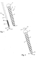
- Figs. 1 to 4 show an embodiment of the system of a bone anchor 1 and an elongate instrument in the form of a cutting device 20.
- the bone anchor 1 comprises a shank 2 with a head 3 at a first end and a free second end 4.
- the head 3 may have a spherically shaped outer surface portion that defines a largest outer diameter of the bone anchor 1.
- a bone thread 5 may be provided on at least a portion of the outer surface of the shank 2.
- the shank 2 may be slightly tapering towards the second end 4.
- An engagement recess 6 for engagement with a tool may be formed at a free end surface of the head 3.
- the bone anchor 1 is cannulated. It includes a channel 7 extending fully through the bone anchor from the head 3 to the second end 4.
- the channel 7 is formed by a coaxial bore extending from the first end to a distance from the second end 4.
- the bore axis defines a longitudinal axis L of the channel.
- An internal advancement structure in the form of an internal thread 8 is provided within the channel adjacent to or close to the second end 4.
- the shoulder 9 functions as an abutment to limit the insertion of an elongate instrument. This permits to achieve an exact positional relationship between the bone anchor 1 and the elongate instrument.
- a smallest inner diameter of the channel 7 in the bone anchor 1 is defined by the internal thread 8.
- At least one, preferably a plurality of radial openings 10, shown in Fig. 6 may be provided for the purpose of forming outlets for bone cement or a pharmaceutical substance to be introduced into the bone anchor 1.
- the elongate instrument in the form of the cutting device 20 is a substantially rod-shaped member that comprises a first end or rear end 21 (shown in Fig. 4 ) and an opposite second or front end 22.
- the cutting device 20 is formed as a cylindrical rod having a length from the rear end 21 to the front end 22 that is greater than the length of the bone anchor 1.
- the length of the cutting device 20 is such, that the cutting device 20 is configured to extend through the passage 7 of the bone anchor 1 and project out of the second end 4 of the bone anchor 1 on one side and is configured to extend through an instrument 100 (shown in Fig. 4 ) for inserting the bone anchor such that the rear end 21 projects out of the instrument 100.
- a tip portion 23 Adjacent to the front end 22, a tip portion 23 is provided that comprises a cutting edge 24.
- the cutting edge 24 may be formed by a recess in the outer surface of the tip portion 23 wherein at least one edge of the recess is configured to perform a cutting function.
- one cutting edge 24 is shown in the figures, a plurality of cutting edges may be provided.
- the shape of the cutting edge or the cutting edges, respectively, may be straight and the cutting edge 24 may extend in longitudinal direction or may be helical or may have any other shape that is configured to cut bone.
- the cutting device 20 Adjacent to or at a distance from the tip portion 23, the cutting device 20 comprises a section with an external advancement structure in the form of an external thread 25 that is configured to cooperate with the internal thread 8 of the bone anchor 1.
- the axial length of the section with the external thread 25 may be greater than or equal to the length of the section with the internal thread 8 of the bone anchor 1 so that, when the cutting device 20 is inserted in the passage 7 of the bone anchor 1, the position of the cutting device 20 can be precisely adjusted over a certain range.
- a small neck portion 26 may be provided following the section with the external thread 25, a small neck portion 26 may be provided.
- the remainder or main portion 27 of the cutting device can be formed as a cylindrical rod with a smooth surface an outer diameter of which is slightly smaller than an inner diameter of the coaxial bore of the passage 7 so that the cutting device 20 can slide within the coaxial bore.
- the cutting device 20 may have at a position on the main portion 27 that is located outside from the bone anchor 1 when the cutting device is inserted into the channel 7, an engagement structure (not shown) for engagement with a portion of the instrument 100.
- an engagement portion aims at rotationally fixing the cutting device 20 relative to the bone anchor 1 when the cutting device 20 has been inserted into the bone anchor and the tip portion 23 extends out of the first end 4 of the bone anchor 1.
- the bone anchor 1 and the cutting device 20 may each be made of a bio-compatible material, for example of titanium or stainless steel, of a bio-compatible alloy, such as NiTi-alloys, for example Nitinol, of magnesium or magnesium alloys, or from a bio-compatible plastic material, such as, for example, polyether ether ketone (PEEK) or poly-1-lactide acid (PLLA).
- a bio-compatible material for example of titanium or stainless steel
- a bio-compatible alloy such as NiTi-alloys, for example Nitinol, of magnesium or magnesium alloys
- a bio-compatible plastic material such as, for example, polyether ether ketone (PEEK) or poly-1-lactide acid (PLLA).
- PEEK polyether ether ketone
- PLLA poly-1-lactide acid
- the bone anchor 1 may be held by the instrument 100 and the cutting device 20 is inserted into the channel 7 of the bone anchor 1 in such a manner that by means of the cooperating threads 8, 25, the length of the cutting device, respectively the cutting portion 23, that protrudes out of the second end 4 of the bone anchor 1 is adjusted.
- the cutting device 20 and the bone anchor 1 could also be pre-assembled and then gripped with an instrument.
- the cutting device 20 is axially fixed to the bone anchor by means of the threads 8, 25 and rotationally fixed through the cooperating engagement portions (not shown) of the cutting device 20 and the instrument 100.
- the bone anchor 1 and the cutting device 20 are configured to be inserted as a unit into the bone.
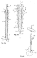
- the instrument 100 is shown as an exemplary embodiment. It comprises a first head engagement portion 101 that engages the head 3 from the outside thereof and a second head engagement portion 102 that engages the head 3 in the recess 6 and a clamping sleeve 103 that presses the first head engagement portion 102 towards the head 3 so that the head 3 of the bone anchor 1 is firmly clamped in the instrument.
- the second head engagement portion 102 comprises a passage for passing through the cutting device 20. As shown in Fig.
- the unit consisting of bone anchor 1 and cutting device 20 is placed to the position where the bone anchor 1 is to be inserted, for example the pedicle of a vertebra 500.
- the cutting edge 24 is used for penetrating the cortical bone.
- the tip portion 23 prepares the pathway for the bone anchor 1 so that the bone anchor 1 can be easily screwed in. Pre-drilling of a hole can be omitted.
- the bone anchor 1 is screwed into the pedicle until the shank 2 is finally implanted and the head 3 projects out of the bone surface.
- the placement of the bone anchor 1 with the cutting device 20 may be carried out with the assistance of an imaging method.
- the cutting device 20 is screwed back and removed from the bone anchor as shown in Fig. 6a . If necessary, the second end 4 can be closed by inserting a plug member and/or bone cement or another substance can be injected which may flow out of the openings 10.
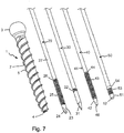
- Fig. 7 depicts the bone anchor 1 and various elongate instruments.
- Such instruments may comprise, for example, the cutting device 20, a medical guide wire 30, such as a modified K-wire, a sensor 40 and a marker 50.
- a medical guide wire 30 such as a modified K-wire
- a sensor 40 such as a sensor
- a marker 50 Each of the instruments together with the bone anchor 1 forms a unit.
- the various instruments and the bone anchor may form a modular system that permits to selectively combine one elongate instrument with the bone anchor 1 depending on the intended use.
- the elongate instrument in the form of a medical guide wire 30, such as a modified K-wire, is shown more in detail in Fig. 8 .
- the guide wire 30 has a substantially smooth outer surface with an outer diameter slightly smaller than an inner diameter of the thread 8 so that the guide wire 30 can be guided through the channel 7 of the bone anchor 1.
- the guide wire 30 has a tip portion 31 that is configured to be pressed into bone.
- an external advancement structure in the form of an external thread 32 is provided that is configured to cooperate with the internal thread 8 of the bone anchor 1.
- an axial length of the external thread 32 is smaller than an axial length of the internal thread 8.
- the axial length of the external thread 32 comprises only as many thread turns as are necessary to axially secure the guide wire 30 against sliding in the channel 7. This may be at least one or only a small number of thread turns.
- the external thread 32 may be located at such a position away from the tip portion 31 that the tip portion 31 and preferably a portion 33 adjacent to the tip portion 31 projects out of the second end 4, when the external thread 32 engages the internal thread 8.
- the guide wire 30 and the bone anchor 1 are assembled by screwing the guide wire 30 into the bone anchor 1 and the system is placed as a unit onto the bone surface so that the tip portion 31 of the guide wire is pressed into the bone. Thereafter, the bone anchor 1 can be screwed down until the threads are out of engagement.
- the guide wire can be used as usual guide wire and the bone anchor 1 and other parts may be guided along the guide wire towards the implantation site.
- the bone anchor and the modified K-wire can be placed as a unit onto the bone surface, the K-wire can be pressed into the bone and screwed further down along the internal thread.
- the elongate instrument in the form of a sensor 40 is shown in Fig. 9 .
- the sensor 40 comprises a housing 41 which is substantially tube-shaped and that is configured to be passed through the channel 7 of the bone anchor 1.
- the housing 41 has a tip portion 42 that may extend through the second end 4.
- the housing 41 comprises an advancement structure in the form of an external thread 43 that is configured to cooperate with the internal thread 8 of the bone anchor 1.
- the axial length of the external thread 43 may be greater than or equal to the axial length of the internal thread 8.
- a neck portion 44 may be present that is followed by a main portion 45 of the housing 41 with a smooth outer surface.
- a sensor element 46 is positioned in the housing 41, wherein the sensor element 46 comprises a tip portion 47 that is configured to sense the respective characteristics, such as, for example, the density of the bone, or which is configured to perform neuro-monitoring. Any other suitable sensor element may be conceivable.
- the sensor 40 may be inserted when the bone anchor has been already inserted into the bone or may be preassembled with the bone anchor 1 and inserted together with the bone anchor 1 into the bone.
- a marker 50 such as a marker for detection through X-rays and/or marking a location on the bone
- the marker 50 is substantially rod-shaped with an inner diameter that is slightly smaller than the inner diameter of the coaxial bore of the bone anchor 1.
- a tip portion 51 is provided which comprises a marker element 52, for example an X-ray detectable element.
- an external advancement structure in the form of an external thread 53 is provided that is configured to cooperate with the internal thread 8 of the bone anchor 1.
- the axial length of the external thread 53 may be smaller or equal to the axial length of the internal thread 8.
- a shoulder 54 that may be adjacent to the external thread 53 is configured to abut against the shoulder or step 9 in the channel 7 to limit the insertion of the marker 50 into the bone anchor.
- the shoulder 54 is located at such a position that when the shoulder 54 abuts against the shoulder 9, the marker element is positioned at the second end 4 and may slightly project out of the second end 4.
- the position of the marker 50 relative to the bone anchor 1 is defined. Therefore, the marker 50 can precisely indicate the position of the bone anchor 1.
- the marker 50 and the bone anchor 1 may be preassembled and inserted into the bone.
- the shape of the bone anchor is not restricted to the shape shown in the embodiment. Any kind of bone anchor may be used, such as for example bone anchors without a bone thread, such as bone nails.
- the head of the bone anchor is shown to be spherically-shaped. However, any other suitable head may be conceivable. In particular, receiving parts for providing a polyaxial bone anchor may be attached to the head.
- the channel of the bone anchor can have a shape other than cylindrical.
- the openings in the wall of the bone anchor can have any shape, in particular a longitudinally extending slit is also conceivable. Finally, the openings can be omitted.
- the advancement structure is shown to be a thread, however, a plurality of concentric ribs to form an advancement structure or another advancement structure that permits to continuously or incrementally advance the cutting device within the channel may be used.
- elongate instruments may also be combined to provide other embodiments of elongate instruments.
Description
- The application relates to a system of bone anchor with a cannulated shank and an elongate instrument that is insertable into the cannulated shank.
- In procedures of spinal surgery, in particular minimally invasive surgery (MIS), it is known to use a guide wire, such as a Kirschner wire (K-wire), that is placed percutaneously through the skin to the intended position of a bone anchor in a vertebra of the vertebral column. In some cases a hole for the bone anchor is pre-drilled and a thread for the bone anchor is pre-tapped. The bone anchor which has a cannulated shank is then guided along the guide wire and finally screwed into the pedicle. Thereafter, the guide wire is removed. Such a bone anchor and procedure is known, for example, from
US 8,690,930 B2 andUS2009/0187220 . - Other bone anchors are known in the art that are cannulated for guiding through a guide pin or a drill. For example,
US 5,098,435 describes a bone stabilizing system including a guide pin and a cannula forming a bone anchor, wherein the guide pin is provided with a drilling means at a forward end thereof for drilling a guide hole into a fractured bone at a predetermined location. The use of the system includes the steps of inserting the guide pin into bone, placing the cannula over the guide pin and advance the cannula into the bone. -
US 7,938,848 B2 describes a pedicle screw having a channel extending along a longitudinal axis of the screw. A drill extends through the channel, wherein a first end of the drill extends out of the distal opening of the channel. -
US 9,095,395 B2 - It is the object of the invention to provide a system of a bone anchor and an elongate instrument which has a broad range of applications and which simplifies surgical procedures, in particular MIS-procedures.
- The object is solved by a system according to
claim 1. Further developments are given in the dependent claims. - The elongate instrument of the system may be, for example, a cutting device, a K-wire, a sensor for sensing characteristics at the implantation site or a marker or any other instrument. Each elongate instrument and the bone anchor together form a unit that can be placed on the implantation site and the surgical step associated with the elongate instrument can be carried out. After that, the instrument can be removed from the channel of the bone anchor and if necessary another type of elongate instrument may be inserted into the channel. Hence, the bone anchor can be assembled selectively with various instruments according to the specific function of the instrument needed. This provides a broad range of applications of the system.
- In the case of the elongate instrument being a cutting device, the system permits to place the bone anchor with the inserted cutting device without using a K-wire, pre-drilling a hole and pre-tapping a thread. This saves time in a surgical procedure. Moreover, a cutting device with a shape and a length of the cutting portion suitable for the specific clinical situation in which the bone anchor is to be used, can be selected.
- In the case of the elongate instrument being a K-wire, the system permits to place the bone anchor with the K-wire as a unit onto the bone surface and press the K-wire tip into the bone. Thereafter, the K-wire can be used as guiding means.
- In the case of the elongate instrument being a marker, the bone anchor and a marker element may have a defined positional relationship relative to each other such that a position of the bone anchor may be precisely detected.
- Further features and advantages will become apparent from the description of embodiments of the invention by means of the accompanying drawings.
- In the drawings:
- Fig. 1
- shows a perspective exploded view of an embodiment of the system of a bone anchor and an elongate instrument in the form of a cutting device.
- Fig. 2
- shows a perspective view of the system of
Fig. 1 in an assembled state. - Fig. 3a
- shows a cross-sectional view of the system of
Figs. 1 and 2 , the cross-section taken in a plane extending through a channel axis of the bone anchor. - Fig. 3b
- shows an enlarged portion of
Fig. 3a . - Fig. 4
- shows a perspective view of an instrument attached to the system of
Figs. 1 to 3b during a step of implanting the bone anchor into the pedicle of a vertebra. - Figs. 5a to 5c
- show cross-sectional views of inserting the system of
Figs. 1 to 3b into the pedicle of a vertebra. - Fig. 6
- shows a cross-sectional view of the inserted bone anchor after removal of the elongate instrument.
- Fig. 7
- shows a perspective view of the bone anchor and various elongate instruments that each can be used with the bone anchor to form a system.
- Fig. 8
- shows a cross-sectional view of a portion of the system with the elongate instrument comprising a modified K-wire.
- Fig. 9
- shows a cross-sectional view of a portion of the system with the elongate instrument comprising a sensor.
- Fig. 10
- shows a cross-sectional view of a portion of the system with the elongate instrument comprising a marker.
-
Figs. 1 to 4 show an embodiment of the system of abone anchor 1 and an elongate instrument in the form of acutting device 20. Thebone anchor 1 comprises ashank 2 with ahead 3 at a first end and a freesecond end 4. Thehead 3 may have a spherically shaped outer surface portion that defines a largest outer diameter of thebone anchor 1. Abone thread 5 may be provided on at least a portion of the outer surface of theshank 2. Theshank 2 may be slightly tapering towards thesecond end 4. An engagement recess 6 for engagement with a tool, may be formed at a free end surface of thehead 3. - As shown more in detail in
Figs. 3a and 3b , thebone anchor 1 is cannulated. It includes achannel 7 extending fully through the bone anchor from thehead 3 to thesecond end 4. Thechannel 7 is formed by a coaxial bore extending from the first end to a distance from thesecond end 4. The bore axis defines a longitudinal axis L of the channel. In a portion adjacent to thesecond end 4 the diameter of thechannel 7 is slightly smaller than that of the coaxial bore. An internal advancement structure in the form of aninternal thread 8 is provided within the channel adjacent to or close to thesecond end 4. Between the coaxial bore and the advancement structure ashoulder 9 may be formed. Theshoulder 9 functions as an abutment to limit the insertion of an elongate instrument. This permits to achieve an exact positional relationship between thebone anchor 1 and the elongate instrument. A smallest inner diameter of thechannel 7 in thebone anchor 1 is defined by theinternal thread 8. - In the wall of the
shank 2, at least one, preferably a plurality ofradial openings 10, shown inFig. 6 , may be provided for the purpose of forming outlets for bone cement or a pharmaceutical substance to be introduced into thebone anchor 1. - The elongate instrument in the form of the cutting
device 20 is a substantially rod-shaped member that comprises a first end or rear end 21 (shown inFig. 4 ) and an opposite second orfront end 22. Basically, the cuttingdevice 20 is formed as a cylindrical rod having a length from therear end 21 to thefront end 22 that is greater than the length of thebone anchor 1. Specifically, the length of the cuttingdevice 20 is such, that the cuttingdevice 20 is configured to extend through thepassage 7 of thebone anchor 1 and project out of thesecond end 4 of thebone anchor 1 on one side and is configured to extend through an instrument 100 (shown inFig. 4 ) for inserting the bone anchor such that therear end 21 projects out of theinstrument 100. Adjacent to thefront end 22, atip portion 23 is provided that comprises acutting edge 24. For example, thecutting edge 24 may be formed by a recess in the outer surface of thetip portion 23 wherein at least one edge of the recess is configured to perform a cutting function. Although onecutting edge 24 is shown in the figures, a plurality of cutting edges may be provided. The shape of the cutting edge or the cutting edges, respectively, may be straight and thecutting edge 24 may extend in longitudinal direction or may be helical or may have any other shape that is configured to cut bone. Adjacent to or at a distance from thetip portion 23, the cuttingdevice 20 comprises a section with an external advancement structure in the form of anexternal thread 25 that is configured to cooperate with theinternal thread 8 of thebone anchor 1. The axial length of the section with theexternal thread 25 may be greater than or equal to the length of the section with theinternal thread 8 of thebone anchor 1 so that, when the cuttingdevice 20 is inserted in thepassage 7 of thebone anchor 1, the position of the cuttingdevice 20 can be precisely adjusted over a certain range. Following the section with theexternal thread 25, asmall neck portion 26 may be provided. The remainder ormain portion 27 of the cutting device can be formed as a cylindrical rod with a smooth surface an outer diameter of which is slightly smaller than an inner diameter of the coaxial bore of thepassage 7 so that the cuttingdevice 20 can slide within the coaxial bore. - Moreover, the cutting
device 20 may have at a position on themain portion 27 that is located outside from thebone anchor 1 when the cutting device is inserted into thechannel 7, an engagement structure (not shown) for engagement with a portion of theinstrument 100. Such an engagement portion aims at rotationally fixing the cuttingdevice 20 relative to thebone anchor 1 when the cuttingdevice 20 has been inserted into the bone anchor and thetip portion 23 extends out of thefirst end 4 of thebone anchor 1. - The
bone anchor 1 and thecutting device 20 may each be made of a bio-compatible material, for example of titanium or stainless steel, of a bio-compatible alloy, such as NiTi-alloys, for example Nitinol, of magnesium or magnesium alloys, or from a bio-compatible plastic material, such as, for example, polyether ether ketone (PEEK) or poly-1-lactide acid (PLLA). In addition, the parts can be made of the same or of different materials from one another. - For assembly, the
bone anchor 1 may be held by theinstrument 100 and thecutting device 20 is inserted into thechannel 7 of thebone anchor 1 in such a manner that by means of the cooperatingthreads portion 23, that protrudes out of thesecond end 4 of thebone anchor 1 is adjusted. It shall be noted that the cuttingdevice 20 and thebone anchor 1 could also be pre-assembled and then gripped with an instrument. By selecting the type of cuttingdevice 20, i.e. in terms of the shape of thecutting edge 24 and the length of thetip portion 23 and by adjusting the length of the portion protruding out from thesecond end 4 of thebone anchor 1 with the threads, it is possible to provide a system adapted to a specific requirement at the implantation site. Finally, the cuttingdevice 20 is axially fixed to the bone anchor by means of thethreads device 20 and theinstrument 100. Hence, thebone anchor 1 and thecutting device 20 are configured to be inserted as a unit into the bone. - Turning now to
Figs. 5a to 5c , thebone anchor 1 with the cuttingdevice 20 and a portion of theinstrument 100 is shown. Theinstrument 100 is shown as an exemplary embodiment. It comprises a firsthead engagement portion 101 that engages thehead 3 from the outside thereof and a secondhead engagement portion 102 that engages thehead 3 in therecess 6 and a clampingsleeve 103 that presses the firsthead engagement portion 102 towards thehead 3 so that thehead 3 of thebone anchor 1 is firmly clamped in the instrument. The secondhead engagement portion 102 comprises a passage for passing through the cuttingdevice 20. As shown inFig. 5a , the unit consisting ofbone anchor 1 and cuttingdevice 20, is placed to the position where thebone anchor 1 is to be inserted, for example the pedicle of avertebra 500. Thecutting edge 24 is used for penetrating the cortical bone. Hence, thetip portion 23 prepares the pathway for thebone anchor 1 so that thebone anchor 1 can be easily screwed in. Pre-drilling of a hole can be omitted. - Then, as shown in
Figs. 5b and 5c , thebone anchor 1 is screwed into the pedicle until theshank 2 is finally implanted and thehead 3 projects out of the bone surface. The placement of thebone anchor 1 with the cuttingdevice 20 may be carried out with the assistance of an imaging method. - When the bone anchor is in the final position, the cutting
device 20 is screwed back and removed from the bone anchor as shown inFig. 6a . If necessary, thesecond end 4 can be closed by inserting a plug member and/or bone cement or another substance can be injected which may flow out of theopenings 10. -
Fig. 7 depicts thebone anchor 1 and various elongate instruments. Such instruments may comprise, for example, the cuttingdevice 20, amedical guide wire 30, such as a modified K-wire, asensor 40 and amarker 50. Each of the instruments together with thebone anchor 1 forms a unit. The various instruments and the bone anchor may form a modular system that permits to selectively combine one elongate instrument with thebone anchor 1 depending on the intended use. - The elongate instrument in the form of a
medical guide wire 30, such as a modified K-wire, is shown more in detail inFig. 8 . Theguide wire 30 has a substantially smooth outer surface with an outer diameter slightly smaller than an inner diameter of thethread 8 so that theguide wire 30 can be guided through thechannel 7 of thebone anchor 1. As usual, theguide wire 30 has atip portion 31 that is configured to be pressed into bone. At a distance from thetip portion 31, an external advancement structure in the form of anexternal thread 32 is provided that is configured to cooperate with theinternal thread 8 of thebone anchor 1. Preferably, an axial length of theexternal thread 32 is smaller than an axial length of theinternal thread 8. More in detail, the axial length of theexternal thread 32 comprises only as many thread turns as are necessary to axially secure theguide wire 30 against sliding in thechannel 7. This may be at least one or only a small number of thread turns. Theexternal thread 32 may be located at such a position away from thetip portion 31 that thetip portion 31 and preferably a portion 33 adjacent to thetip portion 31 projects out of thesecond end 4, when theexternal thread 32 engages theinternal thread 8. - In use, the
guide wire 30 and thebone anchor 1 are assembled by screwing theguide wire 30 into thebone anchor 1 and the system is placed as a unit onto the bone surface so that thetip portion 31 of the guide wire is pressed into the bone. Thereafter, thebone anchor 1 can be screwed down until the threads are out of engagement. In this condition, the guide wire can be used as usual guide wire and thebone anchor 1 and other parts may be guided along the guide wire towards the implantation site. Or, the bone anchor and the modified K-wire can be placed as a unit onto the bone surface, the K-wire can be pressed into the bone and screwed further down along the internal thread. - The elongate instrument in the form of a
sensor 40 is shown inFig. 9 . As shown inFig. 9 , thesensor 40 comprises ahousing 41 which is substantially tube-shaped and that is configured to be passed through thechannel 7 of thebone anchor 1. Thehousing 41 has atip portion 42 that may extend through thesecond end 4. Adjacent to thetip portion 42, thehousing 41 comprises an advancement structure in the form of anexternal thread 43 that is configured to cooperate with theinternal thread 8 of thebone anchor 1. The axial length of theexternal thread 43 may be greater than or equal to the axial length of theinternal thread 8. Adjacent to theexternal thread 43, aneck portion 44 may be present that is followed by a main portion 45 of thehousing 41 with a smooth outer surface. Asensor element 46 is positioned in thehousing 41, wherein thesensor element 46 comprises atip portion 47 that is configured to sense the respective characteristics, such as, for example, the density of the bone, or which is configured to perform neuro-monitoring. Any other suitable sensor element may be conceivable. - The
sensor 40 may be inserted when the bone anchor has been already inserted into the bone or may be preassembled with thebone anchor 1 and inserted together with thebone anchor 1 into the bone. - An elongate instrument in the form of a
marker 50, such as a marker for detection through X-rays and/or marking a location on the bone, is shown more in detail inFig. 10 . Themarker 50 is substantially rod-shaped with an inner diameter that is slightly smaller than the inner diameter of the coaxial bore of thebone anchor 1. Atip portion 51 is provided which comprises amarker element 52, for example an X-ray detectable element. At a distance from thetip portion 51, an external advancement structure in the form of anexternal thread 53 is provided that is configured to cooperate with theinternal thread 8 of thebone anchor 1. The axial length of theexternal thread 53 may be smaller or equal to the axial length of theinternal thread 8. Ashoulder 54 that may be adjacent to theexternal thread 53 is configured to abut against the shoulder orstep 9 in thechannel 7 to limit the insertion of themarker 50 into the bone anchor. Theshoulder 54 is located at such a position that when theshoulder 54 abuts against theshoulder 9, the marker element is positioned at thesecond end 4 and may slightly project out of thesecond end 4. By means of the stop provided by theshoulder 9, the position of themarker 50 relative to thebone anchor 1 is defined. Therefore, themarker 50 can precisely indicate the position of thebone anchor 1. - In use, preferably the
marker 50 and thebone anchor 1 may be preassembled and inserted into the bone. - Further modifications of the above-described system may be conceivable. The shape of the bone anchor is not restricted to the shape shown in the embodiment. Any kind of bone anchor may be used, such as for example bone anchors without a bone thread, such as bone nails. The head of the bone anchor is shown to be spherically-shaped. However, any other suitable head may be conceivable. In particular, receiving parts for providing a polyaxial bone anchor may be attached to the head.
- The channel of the bone anchor can have a shape other than cylindrical. The openings in the wall of the bone anchor can have any shape, in particular a longitudinally extending slit is also conceivable. Finally, the openings can be omitted.
- The advancement structure is shown to be a thread, however, a plurality of concentric ribs to form an advancement structure or another advancement structure that permits to continuously or incrementally advance the cutting device within the channel may be used.
- The various features of the elongate instruments may also be combined to provide other embodiments of elongate instruments.
Claims (14)
- A system of a bone anchor and an elongate instrument includinga bone anchor (1) comprising a shank (2) having a first end (3) and a second end (4) and a channel (7) extending through the shank (2) from the first end (3) to the second end (4), the channel (7) defining a channel axis (L);wherein at or close to the second end (4) of the shank (2) an internal advancement structure (8) is provided at an inner wall of the channel (7); andan elongate instrument (20, 30, 40, 50) that is configured to extend through the channel (7);wherein the elongate instrument (20, 30, 40, 50) comprises a tip portion (23, 31, 42, 51) and an external advancement structure (25, 32, 43, 53) that cooperates with the internal advancement structure (8) of the shank (2) so as to permit the tip portion (23, 31, 42, 51) to be advanced in the channel (7) in the direction towards the second end (4) and to be moved back in the opposite direction towards the first end (3);wherein the elongate instrument with the tip portion (23, 31, 42, 51) is removable from the channel (7) and wherein the tip portion (23, 31, 42, 51) is configured to be advanced in the channel (7) from the first end (3) up to the second end (4); andwherein the internal advancement structure (8) and the external advancement structure (25, 32, 43, 53) are configured to cooperate in such a manner that a position of the elongate instrument (20, 30, 40, 50) relative to the bone anchor is secured in an axial direction against displacement.
- The system of claim 1, wherein the internal advancement structure (8) is an internal thread and the external advancement structure (25, 32, 43, 53) is an external thread.
- The system of claim 2, wherein the internal and the external threads are cylindrical threads.
- The system of one of claims 1 to 3, wherein the tip portion (23, 31, 42, 51) is configured to be advanced in the channel (7) from the first end (3) up to the second end (4), until it extends out of the second end (4).
- The system of one of claims 1 to 4, wherein the elongate instrument (20, 30, 40, 50) has a length such that it extends out of the first end (3) of the shank (2) when the tip portion (23, 31, 42, 51) is at or close to the second end (4) of the channel (7).
- The system of one of claims 1 to 5, wherein the elongate instrument (20, 30, 40, 50) further comprises a first engagement structure that is configured to cooperate with a second engagement structure at the bone anchor or at an instrument to prevent rotation of the elongate instrument (20, 30, 40, 50) relative to the bone anchor.
- The system of one of claims 1 to 6, wherein an axial length of the external advancement structure (25, 32, 43, 53) is greater than or equal to an axial length of internal advancement (8) structure.
- The system of one of claims 1 to 7, wherein the elongate instrument (20, 30, 40, 50) comprises a rear end (21) opposite to the tip portion (23) and a neck (26, 44) adjacent to or close to the external advancement structure (25, 43) at the side towards the rear end (21).
- The system of one of claims 1 to 8, wherein an axial length of the external advancement structure (25, 32) is smaller than an axial length of internal advancement (8) structure, preferably has a length that is sufficient to secure the elongate instrument (20, 30, 40, 50) against sliding in axial direction.
- The system of one of claims 1 to 9, wherein the tip portion (23) comprises at least one cutting edge (24) that is configured to cut into bone.
- The system of one of claims 1 to 10, wherein a stop (9) is provided at the inner wall of the channel (7) to limit the insertion of the elongate instrument into the bone anchor , preferably wherein the tip portion comprises a sensor element (46) or a marker element (52).
- The system of one of claims 1 to 11, wherein the elongate instrument (20, 30, 40, 50) comprises a tube (51).
- The system of one of claims 1 to 11, wherein the elongate instrument is a monolithic part.
- The system of one of claims 1 to 13, wherein further comprising an tool (100) having a first portion that is configured to hold the shank (2) and a second portion that is configured to hold the elongate instrument (20, 30, 40, 50) such that the elongate instrument (2) is axially and rotationally fixed to the shank (2).
Priority Applications (7)
| Application Number | Priority Date | Filing Date | Title |
|---|---|---|---|
| EP18156123.4A EP3524181B1 (en) | 2018-02-09 | 2018-02-09 | System of a bone anchor and an elongate instrument |
| EP21207111.2A EP3970639A1 (en) | 2018-02-09 | 2018-02-09 | System of a bone anchor and an elongate instrument |
| CN201910101530.8A CN110123430A (en) | 2018-02-09 | 2019-02-01 | The system of bone anchor and elongated implement |
| JP2019019022A JP2019136504A (en) | 2018-02-09 | 2019-02-05 | System of bone anchor and elongate instrument |
| US16/270,029 US11191583B2 (en) | 2018-02-09 | 2019-02-07 | System of a bone anchor and an elongate instrument |
| US17/521,418 US20220133374A1 (en) | 2018-02-09 | 2021-11-08 | System of a bone anchor and an elongate instrument |
| JP2023209507A JP2024015370A (en) | 2018-02-09 | 2023-12-12 | System of bone anchors and elongated devices |
Applications Claiming Priority (1)
| Application Number | Priority Date | Filing Date | Title |
|---|---|---|---|
| EP18156123.4A EP3524181B1 (en) | 2018-02-09 | 2018-02-09 | System of a bone anchor and an elongate instrument |
Related Child Applications (1)
| Application Number | Title | Priority Date | Filing Date |
|---|---|---|---|
| EP21207111.2A Division EP3970639A1 (en) | 2018-02-09 | 2018-02-09 | System of a bone anchor and an elongate instrument |
Publications (2)
| Publication Number | Publication Date |
|---|---|
| EP3524181A1 EP3524181A1 (en) | 2019-08-14 |
| EP3524181B1 true EP3524181B1 (en) | 2021-11-10 |
Family
ID=61256555
Family Applications (2)
| Application Number | Title | Priority Date | Filing Date |
|---|---|---|---|
| EP18156123.4A Active EP3524181B1 (en) | 2018-02-09 | 2018-02-09 | System of a bone anchor and an elongate instrument |
| EP21207111.2A Pending EP3970639A1 (en) | 2018-02-09 | 2018-02-09 | System of a bone anchor and an elongate instrument |
Family Applications After (1)
| Application Number | Title | Priority Date | Filing Date |
|---|---|---|---|
| EP21207111.2A Pending EP3970639A1 (en) | 2018-02-09 | 2018-02-09 | System of a bone anchor and an elongate instrument |
Country Status (4)
| Country | Link |
|---|---|
| US (2) | US11191583B2 (en) |
| EP (2) | EP3524181B1 (en) |
| JP (2) | JP2019136504A (en) |
| CN (1) | CN110123430A (en) |
Families Citing this family (8)
| Publication number | Priority date | Publication date | Assignee | Title |
|---|---|---|---|---|
| US11071576B2 (en) * | 2015-10-27 | 2021-07-27 | Spinal Simplicity, Llc | Flexible guide wire with tantalum marker |
| US10973558B2 (en) | 2017-06-12 | 2021-04-13 | K2M, Inc. | Screw insertion instrument and methods of use |
| EP3524181B1 (en) * | 2018-02-09 | 2021-11-10 | Biedermann Technologies GmbH & Co. KG | System of a bone anchor and an elongate instrument |
| WO2019232271A1 (en) * | 2018-05-30 | 2019-12-05 | Goradia Tushar | A guiding device for implantation into bone and related methods of use |
| EP3892215B1 (en) * | 2020-04-09 | 2023-10-11 | Biedermann Technologies GmbH & Co. KG | Surgical instrument |
| AU2022343208A1 (en) * | 2021-09-09 | 2024-03-07 | ExsoMed Corporation | Orthopedic implants and instruments for delivering the same |
| EP4193933A1 (en) | 2021-12-08 | 2023-06-14 | Biedermann Technologies GmbH & Co. KG | Surgical device, in particular for use in spinal or musculoskeletal surgery or in simulated surgery and method of using the same |
| WO2024069795A1 (en) * | 2022-09-28 | 2024-04-04 | 株式会社スパインクロニクルジャパン | Therapeutic instrument and screw |
Family Cites Families (16)
| Publication number | Priority date | Publication date | Assignee | Title |
|---|---|---|---|---|
| DE3936703A1 (en) * | 1989-11-03 | 1991-05-08 | Lutz Biedermann | BONE SCREW |
| US5098435A (en) | 1990-11-21 | 1992-03-24 | Alphatec Manufacturing Inc. | Cannula |
| US5957953A (en) * | 1996-02-16 | 1999-09-28 | Smith & Nephew, Inc. | Expandable suture anchor |
| US7938848B2 (en) | 2004-06-09 | 2011-05-10 | Life Spine, Inc. | Spinal fixation system |
| JP5341901B2 (en) * | 2007-10-25 | 2013-11-13 | スミス アンド ネフュー インコーポレーテッド | Anchor assembly |
| US20090149862A1 (en) * | 2007-12-10 | 2009-06-11 | Sym Partners, Llc | Guide pin for pedicle screw placement and method for use of such guide pin in spinal fusion surgeries |
| US8075579B2 (en) * | 2008-01-17 | 2011-12-13 | Life Spine, Inc. | Pedicle dart system |
| US20090275994A1 (en) * | 2008-04-30 | 2009-11-05 | Phan Christopher U | Apparatus and methods for inserting facet screws |
| EP2140824B1 (en) | 2008-07-01 | 2016-06-08 | Biedermann Technologies GmbH & Co. KG | Cannulated bone anchor with plug member and tool for inserting the plug member into the bone anchor |
| US8403973B2 (en) * | 2008-08-05 | 2013-03-26 | The University Of Toledo | Pedicle screw assembly having a retractable screw tip for facilitating the securement of the pedicle screw assembly to a spinal vertebra |
| DE102011001264A1 (en) | 2011-03-14 | 2012-09-20 | Aesculap Ag | Surgical K-wire and surgical screw system |
| ES2918002T3 (en) * | 2014-12-16 | 2022-07-13 | Spinepoint Llc | bone screw |
| US20160374740A1 (en) * | 2015-06-23 | 2016-12-29 | Sterling Therapeutics, Llc | Retractable screw guide |
| EP4023178B1 (en) * | 2016-02-25 | 2023-11-29 | Biedermann Technologies GmbH & Co. KG | Bone anchor |
| WO2017147537A1 (en) * | 2016-02-26 | 2017-08-31 | Activortho, Inc. | Active compression apparatus, methods of assembly and methods of use |
| EP3524181B1 (en) * | 2018-02-09 | 2021-11-10 | Biedermann Technologies GmbH & Co. KG | System of a bone anchor and an elongate instrument |
-
2018
- 2018-02-09 EP EP18156123.4A patent/EP3524181B1/en active Active
- 2018-02-09 EP EP21207111.2A patent/EP3970639A1/en active Pending
-
2019
- 2019-02-01 CN CN201910101530.8A patent/CN110123430A/en active Pending
- 2019-02-05 JP JP2019019022A patent/JP2019136504A/en active Pending
- 2019-02-07 US US16/270,029 patent/US11191583B2/en active Active
-
2021
- 2021-11-08 US US17/521,418 patent/US20220133374A1/en active Pending
-
2023
- 2023-12-12 JP JP2023209507A patent/JP2024015370A/en active Pending
Also Published As
| Publication number | Publication date |
|---|---|
| JP2019136504A (en) | 2019-08-22 |
| JP2024015370A (en) | 2024-02-01 |
| EP3970639A1 (en) | 2022-03-23 |
| US20190247102A1 (en) | 2019-08-15 |
| EP3524181A1 (en) | 2019-08-14 |
| US11191583B2 (en) | 2021-12-07 |
| US20220133374A1 (en) | 2022-05-05 |
| CN110123430A (en) | 2019-08-16 |
Similar Documents
| Publication | Publication Date | Title |
|---|---|---|
| EP3524181B1 (en) | System of a bone anchor and an elongate instrument | |
| JP7171632B2 (en) | Spinal screw insertion device and method | |
| US20220096138A1 (en) | Bone anchor | |
| US9949776B2 (en) | Awl-tipped pedicle screw and method of implanting same | |
| EP2747687B1 (en) | Bone anchors | |
| US6855105B2 (en) | Endoscopic pedicle probe | |
| US20110196372A1 (en) | Bone Fixing Material and Thighbone Fixing System | |
| CA2928274C (en) | A device for bone support with improved rotational stability | |
| US20070255281A1 (en) | Method for use of dilating stylet and cannula | |
| US20080108991A1 (en) | Method and apparatus for performing pedicle screw fusion surgery | |
| US20070255282A1 (en) | Dilating stylet and cannula | |
| US20120136398A1 (en) | Awl-tipped pedicle screw and method of implanting same | |
| WO2007056379A2 (en) | Application of therapy aligned to an internal target path | |
| US9186192B2 (en) | Instrument for inserting a bone anchoring element and system of such an instrument and a polyaxial bone anchoring element | |
| US20180146990A1 (en) | Apparatus and method for accessing the spine and placing pedicle screws without the use of guide-wires | |
| CN106137369B (en) | Bone nail and percutaneous minimally invasive pedicle fixing system | |
| US9545280B2 (en) | Percutaneous bone screw device | |
| US8343201B2 (en) | Pedicle screw assembly having a retractable screw tip for facilitating the securement of the pedicle screw assembly to a spinal vertebra | |
| EP2380514A1 (en) | Multiple canulated and self guided intramedullary nail | |
| US20130030478A1 (en) | Anchor wire system and method | |
| JP2016533783A (en) | Thread forming Jamshidi assembly | |
| EP4052672A1 (en) | Bone anchor | |
| CN108348284B (en) | Intraosseous screw assembly and internal fixation system comprising same | |
| EP4183353A1 (en) | Instrument with a needle holder for use in surgery | |
| US11950817B2 (en) | Two-part screw systems and methods for implanting same |
Legal Events
| Date | Code | Title | Description |
|---|---|---|---|
| PUAI | Public reference made under article 153(3) epc to a published international application that has entered the european phase |
Free format text: ORIGINAL CODE: 0009012 |
|
| STAA | Information on the status of an ep patent application or granted ep patent |
Free format text: STATUS: REQUEST FOR EXAMINATION WAS MADE |
|
| 17P | Request for examination filed |
Effective date: 20181207 |
|
| AK | Designated contracting states |
Kind code of ref document: A1 Designated state(s): AL AT BE BG CH CY CZ DE DK EE ES FI FR GB GR HR HU IE IS IT LI LT LU LV MC MK MT NL NO PL PT RO RS SE SI SK SM TR |
|
| AX | Request for extension of the european patent |
Extension state: BA ME |
|
| STAA | Information on the status of an ep patent application or granted ep patent |
Free format text: STATUS: EXAMINATION IS IN PROGRESS |
|
| STAA | Information on the status of an ep patent application or granted ep patent |
Free format text: STATUS: EXAMINATION IS IN PROGRESS |
|
| 17Q | First examination report despatched |
Effective date: 20210112 |
|
| GRAP | Despatch of communication of intention to grant a patent |
Free format text: ORIGINAL CODE: EPIDOSNIGR1 |
|
| STAA | Information on the status of an ep patent application or granted ep patent |
Free format text: STATUS: GRANT OF PATENT IS INTENDED |
|
| INTG | Intention to grant announced |
Effective date: 20210525 |
|
| GRAS | Grant fee paid |
Free format text: ORIGINAL CODE: EPIDOSNIGR3 |
|
| GRAA | (expected) grant |
Free format text: ORIGINAL CODE: 0009210 |
|
| STAA | Information on the status of an ep patent application or granted ep patent |
Free format text: STATUS: THE PATENT HAS BEEN GRANTED |
|
| AK | Designated contracting states |
Kind code of ref document: B1 Designated state(s): AL AT BE BG CH CY CZ DE DK EE ES FI FR GB GR HR HU IE IS IT LI LT LU LV MC MK MT NL NO PL PT RO RS SE SI SK SM TR |
|
| REG | Reference to a national code |
Ref country code: GB Ref legal event code: FG4D |
|
| REG | Reference to a national code |
Ref country code: AT Ref legal event code: REF Ref document number: 1445333 Country of ref document: AT Kind code of ref document: T Effective date: 20211115 Ref country code: CH Ref legal event code: EP |
|
| REG | Reference to a national code |
Ref country code: DE Ref legal event code: R096 Ref document number: 602018026307 Country of ref document: DE |
|
| REG | Reference to a national code |
Ref country code: IE Ref legal event code: FG4D |
|
| REG | Reference to a national code |
Ref country code: LT Ref legal event code: MG9D |
|
| REG | Reference to a national code |
Ref country code: NL Ref legal event code: MP Effective date: 20211110 |
|
| REG | Reference to a national code |
Ref country code: AT Ref legal event code: MK05 Ref document number: 1445333 Country of ref document: AT Kind code of ref document: T Effective date: 20211110 |
|
| PG25 | Lapsed in a contracting state [announced via postgrant information from national office to epo] |
Ref country code: RS Free format text: LAPSE BECAUSE OF FAILURE TO SUBMIT A TRANSLATION OF THE DESCRIPTION OR TO PAY THE FEE WITHIN THE PRESCRIBED TIME-LIMIT Effective date: 20211110 Ref country code: LT Free format text: LAPSE BECAUSE OF FAILURE TO SUBMIT A TRANSLATION OF THE DESCRIPTION OR TO PAY THE FEE WITHIN THE PRESCRIBED TIME-LIMIT Effective date: 20211110 Ref country code: FI Free format text: LAPSE BECAUSE OF FAILURE TO SUBMIT A TRANSLATION OF THE DESCRIPTION OR TO PAY THE FEE WITHIN THE PRESCRIBED TIME-LIMIT Effective date: 20211110 Ref country code: BG Free format text: LAPSE BECAUSE OF FAILURE TO SUBMIT A TRANSLATION OF THE DESCRIPTION OR TO PAY THE FEE WITHIN THE PRESCRIBED TIME-LIMIT Effective date: 20220210 Ref country code: AT Free format text: LAPSE BECAUSE OF FAILURE TO SUBMIT A TRANSLATION OF THE DESCRIPTION OR TO PAY THE FEE WITHIN THE PRESCRIBED TIME-LIMIT Effective date: 20211110 |
|
| PG25 | Lapsed in a contracting state [announced via postgrant information from national office to epo] |
Ref country code: IS Free format text: LAPSE BECAUSE OF FAILURE TO SUBMIT A TRANSLATION OF THE DESCRIPTION OR TO PAY THE FEE WITHIN THE PRESCRIBED TIME-LIMIT Effective date: 20220310 Ref country code: SE Free format text: LAPSE BECAUSE OF FAILURE TO SUBMIT A TRANSLATION OF THE DESCRIPTION OR TO PAY THE FEE WITHIN THE PRESCRIBED TIME-LIMIT Effective date: 20211110 Ref country code: PT Free format text: LAPSE BECAUSE OF FAILURE TO SUBMIT A TRANSLATION OF THE DESCRIPTION OR TO PAY THE FEE WITHIN THE PRESCRIBED TIME-LIMIT Effective date: 20220310 Ref country code: PL Free format text: LAPSE BECAUSE OF FAILURE TO SUBMIT A TRANSLATION OF THE DESCRIPTION OR TO PAY THE FEE WITHIN THE PRESCRIBED TIME-LIMIT Effective date: 20211110 Ref country code: NO Free format text: LAPSE BECAUSE OF FAILURE TO SUBMIT A TRANSLATION OF THE DESCRIPTION OR TO PAY THE FEE WITHIN THE PRESCRIBED TIME-LIMIT Effective date: 20220210 Ref country code: NL Free format text: LAPSE BECAUSE OF FAILURE TO SUBMIT A TRANSLATION OF THE DESCRIPTION OR TO PAY THE FEE WITHIN THE PRESCRIBED TIME-LIMIT Effective date: 20211110 Ref country code: LV Free format text: LAPSE BECAUSE OF FAILURE TO SUBMIT A TRANSLATION OF THE DESCRIPTION OR TO PAY THE FEE WITHIN THE PRESCRIBED TIME-LIMIT Effective date: 20211110 Ref country code: HR Free format text: LAPSE BECAUSE OF FAILURE TO SUBMIT A TRANSLATION OF THE DESCRIPTION OR TO PAY THE FEE WITHIN THE PRESCRIBED TIME-LIMIT Effective date: 20211110 Ref country code: GR Free format text: LAPSE BECAUSE OF FAILURE TO SUBMIT A TRANSLATION OF THE DESCRIPTION OR TO PAY THE FEE WITHIN THE PRESCRIBED TIME-LIMIT Effective date: 20220211 Ref country code: ES Free format text: LAPSE BECAUSE OF FAILURE TO SUBMIT A TRANSLATION OF THE DESCRIPTION OR TO PAY THE FEE WITHIN THE PRESCRIBED TIME-LIMIT Effective date: 20211110 |
|
| PG25 | Lapsed in a contracting state [announced via postgrant information from national office to epo] |
Ref country code: SM Free format text: LAPSE BECAUSE OF FAILURE TO SUBMIT A TRANSLATION OF THE DESCRIPTION OR TO PAY THE FEE WITHIN THE PRESCRIBED TIME-LIMIT Effective date: 20211110 Ref country code: SK Free format text: LAPSE BECAUSE OF FAILURE TO SUBMIT A TRANSLATION OF THE DESCRIPTION OR TO PAY THE FEE WITHIN THE PRESCRIBED TIME-LIMIT Effective date: 20211110 Ref country code: RO Free format text: LAPSE BECAUSE OF FAILURE TO SUBMIT A TRANSLATION OF THE DESCRIPTION OR TO PAY THE FEE WITHIN THE PRESCRIBED TIME-LIMIT Effective date: 20211110 Ref country code: EE Free format text: LAPSE BECAUSE OF FAILURE TO SUBMIT A TRANSLATION OF THE DESCRIPTION OR TO PAY THE FEE WITHIN THE PRESCRIBED TIME-LIMIT Effective date: 20211110 Ref country code: DK Free format text: LAPSE BECAUSE OF FAILURE TO SUBMIT A TRANSLATION OF THE DESCRIPTION OR TO PAY THE FEE WITHIN THE PRESCRIBED TIME-LIMIT Effective date: 20211110 Ref country code: CZ Free format text: LAPSE BECAUSE OF FAILURE TO SUBMIT A TRANSLATION OF THE DESCRIPTION OR TO PAY THE FEE WITHIN THE PRESCRIBED TIME-LIMIT Effective date: 20211110 |
|
| REG | Reference to a national code |
Ref country code: DE Ref legal event code: R097 Ref document number: 602018026307 Country of ref document: DE |
|
| PLBE | No opposition filed within time limit |
Free format text: ORIGINAL CODE: 0009261 |
|
| STAA | Information on the status of an ep patent application or granted ep patent |
Free format text: STATUS: NO OPPOSITION FILED WITHIN TIME LIMIT |
|
| PG25 | Lapsed in a contracting state [announced via postgrant information from national office to epo] |
Ref country code: MC Free format text: LAPSE BECAUSE OF FAILURE TO SUBMIT A TRANSLATION OF THE DESCRIPTION OR TO PAY THE FEE WITHIN THE PRESCRIBED TIME-LIMIT Effective date: 20211110 |
|
| 26N | No opposition filed |
Effective date: 20220811 |
|
| REG | Reference to a national code |
Ref country code: BE Ref legal event code: MM Effective date: 20220228 |
|
| PG25 | Lapsed in a contracting state [announced via postgrant information from national office to epo] |
Ref country code: LU Free format text: LAPSE BECAUSE OF NON-PAYMENT OF DUE FEES Effective date: 20220209 Ref country code: AL Free format text: LAPSE BECAUSE OF FAILURE TO SUBMIT A TRANSLATION OF THE DESCRIPTION OR TO PAY THE FEE WITHIN THE PRESCRIBED TIME-LIMIT Effective date: 20211110 |
|
| PG25 | Lapsed in a contracting state [announced via postgrant information from national office to epo] |
Ref country code: SI Free format text: LAPSE BECAUSE OF FAILURE TO SUBMIT A TRANSLATION OF THE DESCRIPTION OR TO PAY THE FEE WITHIN THE PRESCRIBED TIME-LIMIT Effective date: 20211110 |
|
| PG25 | Lapsed in a contracting state [announced via postgrant information from national office to epo] |
Ref country code: FR Free format text: LAPSE BECAUSE OF NON-PAYMENT OF DUE FEES Effective date: 20220228 |
|
| PG25 | Lapsed in a contracting state [announced via postgrant information from national office to epo] |
Ref country code: IE Free format text: LAPSE BECAUSE OF NON-PAYMENT OF DUE FEES Effective date: 20220209 |
|
| PG25 | Lapsed in a contracting state [announced via postgrant information from national office to epo] |
Ref country code: BE Free format text: LAPSE BECAUSE OF NON-PAYMENT OF DUE FEES Effective date: 20220228 |
|
| PGFP | Annual fee paid to national office [announced via postgrant information from national office to epo] |
Ref country code: CH Payment date: 20230307 Year of fee payment: 6 |
|
| PG25 | Lapsed in a contracting state [announced via postgrant information from national office to epo] |
Ref country code: IT Free format text: LAPSE BECAUSE OF FAILURE TO SUBMIT A TRANSLATION OF THE DESCRIPTION OR TO PAY THE FEE WITHIN THE PRESCRIBED TIME-LIMIT Effective date: 20211110 |
|
| PGFP | Annual fee paid to national office [announced via postgrant information from national office to epo] |
Ref country code: GB Payment date: 20230221 Year of fee payment: 6 Ref country code: DE Payment date: 20230227 Year of fee payment: 6 |
|
| P01 | Opt-out of the competence of the unified patent court (upc) registered |
Effective date: 20230526 |