WO2024257825A1 - ロック装置 - Google Patents
ロック装置 Download PDFInfo
- Publication number
- WO2024257825A1 WO2024257825A1 PCT/JP2024/021476 JP2024021476W WO2024257825A1 WO 2024257825 A1 WO2024257825 A1 WO 2024257825A1 JP 2024021476 W JP2024021476 W JP 2024021476W WO 2024257825 A1 WO2024257825 A1 WO 2024257825A1
- Authority
- WO
- WIPO (PCT)
- Prior art keywords
- lock
- inlet
- charging connector
- detection switch
- moving
- Prior art date
- Legal status (The legal status is an assumption and is not a legal conclusion. Google has not performed a legal analysis and makes no representation as to the accuracy of the status listed.)
- Ceased
Links
Images










Classifications
-
- B—PERFORMING OPERATIONS; TRANSPORTING
- B60—VEHICLES IN GENERAL
- B60L—PROPULSION OF ELECTRICALLY-PROPELLED VEHICLES; SUPPLYING ELECTRIC POWER FOR AUXILIARY EQUIPMENT OF ELECTRICALLY-PROPELLED VEHICLES; ELECTRODYNAMIC BRAKE SYSTEMS FOR VEHICLES IN GENERAL; MAGNETIC SUSPENSION OR LEVITATION FOR VEHICLES; MONITORING OPERATING VARIABLES OF ELECTRICALLY-PROPELLED VEHICLES; ELECTRIC SAFETY DEVICES FOR ELECTRICALLY-PROPELLED VEHICLES
- B60L53/00—Methods of charging batteries, specially adapted for electric vehicles; Charging stations or on-board charging equipment therefor; Exchange of energy storage elements in electric vehicles
- B60L53/10—Methods of charging batteries, specially adapted for electric vehicles; Charging stations or on-board charging equipment therefor; Exchange of energy storage elements in electric vehicles characterised by the energy transfer between the charging station and the vehicle
- B60L53/14—Conductive energy transfer
- B60L53/16—Connectors, e.g. plugs or sockets, specially adapted for charging electric vehicles
-
- H—ELECTRICITY
- H01—ELECTRIC ELEMENTS
- H01R—ELECTRICALLY-CONDUCTIVE CONNECTIONS; STRUCTURAL ASSOCIATIONS OF A PLURALITY OF MUTUALLY-INSULATED ELECTRICAL CONNECTING ELEMENTS; COUPLING DEVICES; CURRENT COLLECTORS
- H01R13/00—Details of coupling devices of the kinds covered by groups H01R12/70 or H01R24/00 - H01R33/00
- H01R13/62—Means for facilitating engagement or disengagement of coupling parts or for holding them in engagement
- H01R13/639—Additional means for holding or locking coupling parts together, after engagement, e.g. separate keylock, retainer strap
-
- H—ELECTRICITY
- H01—ELECTRIC ELEMENTS
- H01R—ELECTRICALLY-CONDUCTIVE CONNECTIONS; STRUCTURAL ASSOCIATIONS OF A PLURALITY OF MUTUALLY-INSULATED ELECTRICAL CONNECTING ELEMENTS; COUPLING DEVICES; CURRENT COLLECTORS
- H01R13/00—Details of coupling devices of the kinds covered by groups H01R12/70 or H01R24/00 - H01R33/00
- H01R13/64—Means for preventing incorrect coupling
-
- H—ELECTRICITY
- H01—ELECTRIC ELEMENTS
- H01R—ELECTRICALLY-CONDUCTIVE CONNECTIONS; STRUCTURAL ASSOCIATIONS OF A PLURALITY OF MUTUALLY-INSULATED ELECTRICAL CONNECTING ELEMENTS; COUPLING DEVICES; CURRENT COLLECTORS
- H01R13/00—Details of coupling devices of the kinds covered by groups H01R12/70 or H01R24/00 - H01R33/00
- H01R13/66—Structural association with built-in electrical component
- H01R13/70—Structural association with built-in electrical component with built-in switch
- H01R13/703—Structural association with built-in electrical component with built-in switch operated by engagement or disengagement of coupling parts, e.g. dual-continuity coupling part
-
- H—ELECTRICITY
- H02—GENERATION; CONVERSION OR DISTRIBUTION OF ELECTRIC POWER
- H02J—ELECTRIC POWER NETWORKS; CIRCUIT ARRANGEMENTS OR SYSTEMS FOR SUPPLYING OR DISTRIBUTING ELECTRIC POWER; SYSTEMS FOR STORING ELECTRIC ENERGY
- H02J7/00—Circuit arrangements for charging or discharging batteries or for supplying loads from batteries
-
- Y—GENERAL TAGGING OF NEW TECHNOLOGICAL DEVELOPMENTS; GENERAL TAGGING OF CROSS-SECTIONAL TECHNOLOGIES SPANNING OVER SEVERAL SECTIONS OF THE IPC; TECHNICAL SUBJECTS COVERED BY FORMER USPC CROSS-REFERENCE ART COLLECTIONS [XRACs] AND DIGESTS
- Y02—TECHNOLOGIES OR APPLICATIONS FOR MITIGATION OR ADAPTATION AGAINST CLIMATE CHANGE
- Y02T—CLIMATE CHANGE MITIGATION TECHNOLOGIES RELATED TO TRANSPORTATION
- Y02T10/00—Road transport of goods or passengers
- Y02T10/60—Other road transportation technologies with climate change mitigation effect
- Y02T10/70—Energy storage systems for electromobility, e.g. batteries
-
- Y—GENERAL TAGGING OF NEW TECHNOLOGICAL DEVELOPMENTS; GENERAL TAGGING OF CROSS-SECTIONAL TECHNOLOGIES SPANNING OVER SEVERAL SECTIONS OF THE IPC; TECHNICAL SUBJECTS COVERED BY FORMER USPC CROSS-REFERENCE ART COLLECTIONS [XRACs] AND DIGESTS
- Y02—TECHNOLOGIES OR APPLICATIONS FOR MITIGATION OR ADAPTATION AGAINST CLIMATE CHANGE
- Y02T—CLIMATE CHANGE MITIGATION TECHNOLOGIES RELATED TO TRANSPORTATION
- Y02T10/00—Road transport of goods or passengers
- Y02T10/60—Other road transportation technologies with climate change mitigation effect
- Y02T10/7072—Electromobility specific charging systems or methods for batteries, ultracapacitors, supercapacitors or double-layer capacitors
-
- Y—GENERAL TAGGING OF NEW TECHNOLOGICAL DEVELOPMENTS; GENERAL TAGGING OF CROSS-SECTIONAL TECHNOLOGIES SPANNING OVER SEVERAL SECTIONS OF THE IPC; TECHNICAL SUBJECTS COVERED BY FORMER USPC CROSS-REFERENCE ART COLLECTIONS [XRACs] AND DIGESTS
- Y02—TECHNOLOGIES OR APPLICATIONS FOR MITIGATION OR ADAPTATION AGAINST CLIMATE CHANGE
- Y02T—CLIMATE CHANGE MITIGATION TECHNOLOGIES RELATED TO TRANSPORTATION
- Y02T90/00—Enabling technologies or technologies with a potential or indirect contribution to GHG emissions mitigation
- Y02T90/10—Technologies relating to charging of electric vehicles
- Y02T90/14—Plug-in electric vehicles
Definitions
- the present invention relates to a locking device.
- the battery is charged by connecting a power supply cable extending from a charging facility to a power supply port (inlet) on the vehicle body (see, for example, Patent Document 1).
- the vehicle charging inlet shown in Patent Document 1 is provided with a locking device that locks the charging connector so that it does not come loose from the inlet while the vehicle is being charged.
- the locking device is activated and the locking pin is inserted into the engagement portion (hole) of the charging connector and moves to the locked position. This prevents the charging connector from coming loose from the inlet.
- the vehicle charging inlet disclosed in Patent Document 1 is configured not to start charging unless both a detection portion that detects the operation of the lock pin and a detection portion that detects a failure of the charging connector are on.
- the detection unit that detects malfunctions in the charging connector is located on the inlet side, and the detection unit that detects the operation of the lock pin is located on the actuator side outside the inlet, resulting in complex wiring.
- the object of the present invention is to provide a locking device that can simplify wiring.
- the locking device includes a locking member, a drive unit, a moving member, a lock detection unit, and a moving member detection unit.
- the locking member is movable between a locked position that restricts the movement of an engaging portion of a charging connector inserted into a charging inlet from an engaged state in which it is engaged with an engaged portion of the inlet to a disengaged state, and an unlocked position that releases the restriction on the movement of the engaging portion.
- the drive unit moves the locking member between the locked position and the unlocked position.
- the moving member moves to a predetermined position by the engaging portion when the charging connector is inserted into the inlet.
- the lock detection unit detects the movement of the locking member to the locked position.
- the moving member detection unit detects the movement of the moving member to the predetermined position.
- the present invention provides a locking device that allows for simplified wiring.
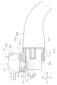
- FIG. 1 is a perspective view showing a part of a vehicle in which a lock device according to a first embodiment is disposed and a charging connector
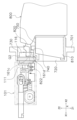
- FIG. 4 is a schematic side view showing the charging connector inserted into the inlet of the vehicle.
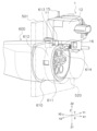
- 1 is a perspective view of a part of a vehicle in which a lock device according to a first embodiment is disposed and a charging connector, as viewed from the vehicle side;
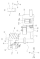
- 1 is a schematic side view illustrating a state in which the charging connector is inserted into an inlet of a vehicle when a tip portion of the charging connector is broken;
- FIG. 2 is a perspective view showing the locking device according to the first embodiment.
- FIG. 4 is a perspective view showing the locking device with the first housing portion removed.
- FIG. 1A is a perspective view showing a rack member, a lock pin, a detection pin, a pin support portion, etc. of the locking device
- FIG. 1B is a diagram showing the positional relationship between a pin body and the lock pin as viewed from the X1 direction side
- FIG. 7B is a perspective view of FIG. 7A viewed from a different direction.
- 13 is a diagram showing a state in which the switch pressing portion abuts against the movement detection switch and presses the movement detection switch.
- FIG. 6A and 6B are diagrams showing electrical connections between the lock detection switch and the movement detection switch.
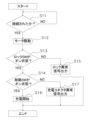
- FIG. 4 is a flowchart for explaining a control operation on the vehicle body side until charging is started.
- FIG. 4 is a flowchart for explaining a control operation on the vehicle body side until charging is started.
- FIG. 11 is a perspective view showing a part of a vehicle in which a lock device according to a second embodiment is disposed and a charging connector.
- FIG. 4 is a schematic side view showing the charging connector inserted into the inlet of the vehicle.
- 11 is a schematic side view illustrating a state in which the charging connector is inserted into an inlet of a vehicle when an engagement claw of the charging connector is broken;
- FIG. 11 is a perspective view of a locking device according to a second embodiment of the present invention.
- FIG. 2 is a perspective view of the locking device with the second housing part removed;
- FIG. 17 is a cross-sectional view of the locking device taken along line B-B of FIG. 16 .
- FIG. 13 is a diagram illustrating a state in which the lock pin is disposed at the unlocked position and the detection member is disposed at the non-pushed position.
- FIG. 13 is a diagram illustrating a state in which the lock pin is disposed at the lock position and the detection member is disposed at the pressed-in position.
- 4A is a perspective view showing the vicinity of a rotation portion of the charging connector
- FIG. 4B is a perspective view showing a state in which a detection member is pressed in by an engagement claw.
- the locking device of this embodiment can be used to lock a charging connector (an example of an object) connected to a power inlet of a vehicle body.
- the locking device is generally provided near the power inlet of the vehicle body, but the location of the locking device is not limited as long as it is possible to lock the charging connector and prevent it from falling off from the power inlet of the vehicle body.
- the locking device does not have to lock the charging connector itself, and may lock a member connected to the charging connector, as long as it can prevent the charging connector from falling off from the power inlet of the vehicle body.
- the locking device protrudes a lock pin and restricts the movement of the charging connector, thereby preventing the charging connector from being removed from the power inlet (inlet).
- the locking device can also be used as a locking device that restricts the movement of an object by advancing a pin, such as a fuel lid locking device.
- FIG. 1 is a perspective view showing a part of a vehicle 500 in which a locking device 1 of the first embodiment is arranged, and a charging connector 600.
- Fig. 2 is a side schematic view showing a state in which the charging connector 600 is inserted into an inlet 520 of the vehicle 500.
- the vehicle 500 which has a battery as a driving source, for example, is equipped with a charging system capable of charging the battery of the vehicle 500 from an external power source.
- the inlet 520 is arranged on a side surface 501 of the vehicle 500.
- FIG. 3 is a perspective view of a part of a vehicle in which the locking device 1 of the first embodiment is disposed and a charging connector, as viewed from the vehicle side.
- the side surface 501 is indicated by a two-dot chain line, and the configuration behind the side surface 501 is indicated by a solid line in the figure.
- the charging connector 600 has an insertion portion 610 that is inserted into the inlet 520.
- the insertion portion 610 has a connector side connection portion 611 that is electrically connected to the inlet 520, and a protrusion portion 612 (engagement portion) that is arranged to surround the connector side connection portion 611.
- the inlet 520 has an inlet side connection portion 521 and an insertion hole 522 (engaged portion).
- the inlet side connection portion 521 is electrically connected to the connector side connection portion 611.
- the protrusion portion 612 is inserted into the insertion hole 522.
- the locking device 1 is disposed above the inlet 520 of the vehicle 500.
- the locking device 1 is disposed so that its lock pin 11 moves in the vertical direction.
- the arrangement of the locking device 1 is not limited to this, and the location and orientation can be changed as appropriate to suit the object to be locked.
- the lock pin 11 When the charging connector 600 is inserted into the inlet 520 to supply power, the lock pin 11 is inserted into a lock hole 613 provided in a part of the protrusion 612. When the lock pin 11 is inserted into the lock hole 613, the protrusion 612 is prevented from coming out of the insertion hole 522. In this way, the position of the lock pin 11 that restricts the movement of the protrusion 612 from a state where it is inserted into the insertion hole 522 (engaged state) to a state where it is removed from the insertion hole 522 (disengaged state) is shown as the lock position P1.
- the lock pin 11 moves upward and is removed from the lock hole 613. In this manner, the position of the lock pin 11 that releases the restriction on the movement of the protrusion 612 from a state where it is inserted into the insertion hole 522 (engaged state) to a state where it is removed from the insertion hole 522 (disengaged state) is shown as the unlocked position P2 (dashed double-dashed line).
- the lock device 1 is provided with a detection pin 16 (moving member) that detects damage to the tip portion 614.
- the detection pin 16 is inserted into a through hole 523 formed in the inlet 520.
- the through hole 523 is formed so as to penetrate to the outside opposite the insertion hole 522 of the inlet 520 at the bottom of the insertion hole 522 of the inlet 520.
- the through hole 523 is formed along the X direction described later.
- the detection pin 16 protrudes from the outside opposite the insertion hole 522 of the inlet 520 toward the through hole 523 provided at the bottom of the insertion hole 522 of the inlet 520.
- the tip portion 614 of the charging connector 600 moves the detection pin 16.
- the position where the detection pin 16 is pushed in by the tip portion 614 is shown as the pushed-in position Q1 (predetermined position).
- the detection pin 16 does not move because it cannot be pushed by the tip portion 614.
- the position where the detection pin 16 is not pressed is shown as the non-pushed position Q2. In this way, even when the charging connector 600 is inserted into the inlet 520, damage to the tip portion 614 can be detected because the detection pin 16 does not move from the non-pushed position Q2 to the pushed position Q1.
- the moving direction of the locking pin 11 of the locking device 1 is the Z direction
- the moving direction from the unlocked position P2 to the locked position P1 in the Z direction is the Z1
- the moving direction from the locked position P1 to the unlocked position P2 is the Z2.
- the moving direction of the detection pin 16 is the X direction
- the direction in the X direction in which the detection pin 16 (moving member) is pushed in by the tip portion 614 is the X1
- the opposite of the X1 direction is the X2 direction.
- the X direction is a direction perpendicular to the Z direction.
- the X1 direction can also be said to be a direction in which the charging connector 600 is inserted into the inlet 520
- the X2 direction can also be said to be a direction in which the charging connector 600 is pulled out from the inlet 520.
- the direction perpendicular to the Z direction and the X direction is the Y direction.
- the Y direction is a direction perpendicular to the paper surface in FIG. 2. Of the Y directions, the front direction of the paper surface in FIG. 2 is the Y1 direction, and the depth direction of the paper surface in FIG. 2 is the Y2 direction.
- perpendicular does not necessarily mean “perpendicular” in the strict sense, but may include a margin of error, as long as it is socially acceptable to recognize it as perpendicular.
- parallel does not necessarily mean “parallel” in the strict sense, but may include a margin of error, as long as it is socially acceptable to recognize it as perpendicular.
- FIG. 5 is a perspective view of the locking device 1.
- the locking device 1 includes a locking pin 11, a housing 12 through which the locking pin 11 is inserted, and a detection pin 16 movably supported on the housing 12.
- the housing 12 has a first housing part 21 and a second housing part 22.
- the first housing part 21 is box-shaped with one side open.
- the face of the first housing part 21 on the Z1 direction side is open.
- the second housing part 22 is plate-shaped and is positioned so as to cover the opening of the first housing part 21.
- a connector part 23 is provided on the face of the second housing part 22 on the X1 direction side for electrically connecting to the vehicle controller.
- Figure 6 is an oblique view of the locking device 1 with the first housing part 21 removed, viewed from the Z2 direction.
- the locking device 1 has the above-mentioned lock pin 11 (locking member), the above-mentioned housing 12, a drive unit 13, a lock detection unit 14, an emergency cable 15, a detection pin 16 (moving member), a pin support unit 17, a biasing member 18, a movement detection unit 19 (moving member detection unit), and an output unit 20 ( Figure 10 described below).
- the lock pin 11 can move in the Z direction between a lock position P1 that restricts the movement of the object and an unlock position P2 that releases the restriction on the movement of the object.
- the drive unit 13 moves the lock pin 11 between the lock position P1 and the unlock position P2.
- the lock detection unit 14 detects the movement of the lock pin 11 to the lock position P1.
- the emergency cable 15 is provided to be pulled by the operator to move the lock pin 11 from the lock position P1 to the unlock position P2 and release the lock.
- the detection pin 16 is provided to detect damage to the tip portion 614 of the charging connector 600.
- the pin support unit 17 supports the detection pin 16 on the housing 12 so that it can move in the X direction.
- the movement detection unit 19 detects that the detection pin 16 has moved to the push-in position Q1.
- the output unit 20 outputs the detection results by the lock detection unit 14 and the movement detection unit 19 to the vehicle controller 81.
- the drive unit 13 has a motor 30, a first transmission gear 31, a second transmission gear 32, a third transmission gear 33, a fourth transmission gear 34, a fifth transmission gear 35, and a rack member 36.
- the motor 30 is disposed such that the output shaft 30a is aligned along the Y direction.
- the first transmission gear 31 is fixed to the output shaft 30a.
- the first transmission gear 31 rotates together with the rotation of the output shaft 30a.
- the first transmission gear 31 is a helical gear.
- the second transmission gear 32 meshes with the first transmission gear 31.
- the second transmission gear 32 is rotatably supported by the housing 12.
- the rotation axis of the second transmission gear 32 is parallel to the Y direction.
- the second transmission gear 32 is a helical gear.
- the second transmission gear 32 is disposed on the X2 direction side of the first transmission gear 31.
- the third transmission gear 33 is arranged coaxially with the second transmission gear 32.
- the third transmission gear 33 is rotatably supported by the housing 12.
- the third transmission gear 33 is a helical gear.
- the third transmission gear 33 is arranged outside the housing 12 (on the Y1 direction side) relative to the second transmission gear 32.
- the third transmission gear 33 is connected to the second transmission gear 32.
- the third transmission gear 33 rotates together with the rotation of the second transmission gear 32.
- the fourth transmission gear 34 meshes with the third transmission gear 33.
- the fourth transmission gear 34 is rotatably supported by the housing 12.
- the fourth transmission gear 34 is disposed on the opposite side of the third transmission gear 33 from the motor 30 (the X2 direction side).
- the fifth transmission gear 35 is arranged coaxially with the fourth transmission gear 34.
- the fifth transmission gear 35 is rotatably supported by the housing 12.
- the fifth transmission gear 35 is a helical gear.
- the fifth transmission gear 35 is arranged on the inner side (Y2 direction side) of the housing 12 relative to the fourth transmission gear 34.
- the fifth transmission gear 35 is connected to the fourth transmission gear 34.
- the fifth transmission gear 35 rotates together with the rotation of the fourth transmission gear 34.
- FIG. 7(a) is an oblique view showing the rack member 36, lock pin 11, lock detector 14, detector pin 16, and movement detector 19.
- FIG. 8 is a view of FIG. 7(a) as seen from the Z1 direction side.
- the rack member 36 engages with the end 11a of the lock pin 11 inside the housing 12.
- the rack member 36 has a main body 41, a switch pressing portion 42 (second operating portion), and a rack gear 43.
- the main body 41 is a member having an external shape of a substantially rectangular parallelepiped.
- the switch pressing portion 42 protrudes from the main body 41 in the Y2 direction.
- the switch pressing portion 42 presses the lock detection switch 14a of the lock detection portion 14.
- the rack gear 43 is disposed on the surface of the main body 41 on the X1 direction side.
- the rack gear 43 is disposed along the Z direction. The peaks of the rack gear 43 are inclined with respect to the Y direction and mesh with the fifth transmission gear 35.
- the first transmission gear 31 rotates.
- the rotation of the first transmission gear 31 rotates the second transmission gear 32 that is engaged with the first transmission gear 31.
- the rotation of the second transmission gear 32 rotates the third transmission gear 33 that is coaxial with and connected to the second transmission gear 32.
- the rotation of the third transmission gear 33 rotates the fourth transmission gear 34 that is engaged with the third transmission gear 33.
- the rotation of the fourth transmission gear 34 rotates the fifth transmission gear 35 that is coaxial with and connected to the fourth transmission gear 34.
- the rotation of the fifth transmission gear 35 moves the rack member 36 in the Z direction, and the lock pin 11 that is engaged with the rack member 36 also moves in the Z direction.
- the lock detection portion 14 is fixed to the second housing portion 22.
- the lock detection portion 14 is disposed between the switch pressing portion 42 and the second housing portion 22.
- the lock detection portion 14 has a lock detection switch 14a.
- the lock detection switch 14a is disposed facing the Z2 direction. When the lock pin 11 moves together with the rack member 36 from the unlocked position P2 toward the locked position P1, the lock detection switch 14a is pressed by the rack member 36. This makes it possible to detect that the lock pin 11 has moved to the locked position P1.
- the emergency cable 15 is engaged with the rack member 36. As shown in Figures 3 and 6, the emergency cable 15 extends outside the housing 12. When the operator pulls the emergency cable 15 in the Z2 direction, the rack member 36 can be moved in the Z2 direction. This causes the lock pin 11 engaged with the rack member 36 to also move in the Z2 direction, and the lock pin 11 can be moved to the unlock position P2.
- Fig. 9 is a bottom view of the lock device 1. As shown in Figs. 4 and 9, the detection pin 16 is arranged along the X direction. The detection pin 16 is arranged along the pushing direction of the charging connector 600 into the inlet 520. The detection pin 16 is arranged on the outside (Z1 direction side) of the outer surface 22a of the second housing portion 22. The outer surface 22a is perpendicular to the Z1 direction and faces the Z1 direction side.
- the pin support portion 17 supports the detection pin 16 on the housing 12 so as to be movable in the X direction.
- the pin support portion 17 has a first support portion 51 and a second support portion 52.
- the first support portion 51 is arranged from the outer surface 22a toward the Z1 direction.
- the first support portion 51 has a pair of first side walls 51a and a first through hole forming wall 51b.
- the pair of first side walls 51a are arranged opposite each other in the Y direction.
- Each of the first side walls 51a is arranged perpendicular to the Y direction.
- the first through hole forming wall 51b connects between the ends of the pair of first side walls 51a on the X2 direction side.
- the first through hole forming wall 51b is arranged perpendicular to the X direction.
- the first through hole forming wall 51b has a through hole penetrating in the X direction.
- the first side wall 51a on the Y2 direction side of the pair of first side walls 51a has a notch 51c.
- a movement detection switch 19a (described later) is inserted into the notch 51c.
- a gap is formed between the first through-hole forming wall 51b and the outer surface 22a. As shown in FIG. 5, the end 63d of the switch pressing portion 63 (described later) on the X1 direction side can be inserted into this gap.
- the second support portion 52 is arranged from the outer surface 22a toward the Z1 direction.
- the second support portion 52 is arranged on the X1 direction side of the first support portion 51.
- the second support portion 52 has a pair of second side walls 52a and a second through hole forming wall 52b.
- the pair of second side walls 52a are arranged opposite each other in the Y direction.
- Each of the second side walls 52a is arranged perpendicular to the Y direction.
- the pair of second side walls 52a are arranged on the outer side of the pair of first side walls 51a in the Y direction.
- the pair of second side walls 52a are arranged so as to face the ends of the pair of first side walls 51a on the X1 direction side.
- the second through hole forming wall 52b connects between the ends of the pair of second side walls 52a on the X1 direction side.
- the second through hole forming wall 52b is arranged perpendicular to the X direction.
- the second through hole forming wall 52b is disposed opposite the first through hole forming wall 51b in the X direction.
- the lock pin 11 is inserted into the through hole of the first through hole forming wall 51b and the through hole of the second through hole forming wall 52b.
- the first support part 51 is omitted.
- the detection pin 16 has a pin body 61, a restricting portion 62, and a switch pressing portion 63 (first operating portion).
- the pin body 61 has a shape extending in the X direction.
- the pin body 61 is, for example, cylindrical.
- the pin body 61 is inserted into the through hole of the first through hole forming wall 51b and the through hole of the second through hole forming wall 52b.
- the pin body 61 is arranged along the X direction.
- FIG. 7(b) is a diagram showing the positional relationship between the pin body 61 and the lock pin 11 as viewed from the X1 direction side. As shown in FIG. 7(b), when the lock pin 11 is arranged in the lock position P1, the pin body 61 overlaps with the lock pin 11 as viewed along the X direction.
- the restricting portion 62 is disposed on the pin body 61 as shown in FIG. 7(a).
- the restricting portion 62 is disposed between the first through-hole forming wall 51b and the second through-hole forming wall 52b as shown in FIG. 5.
- the restricting portion 62 extends from the pin body 61 toward the outer surface 22a (Z2 direction).
- the restricting portion 62 is disposed between the pair of first side walls 51a as shown in FIG. 9.
- the locking device 1 has a biasing member 18 that biases the detection pin 16 in the X2 direction toward the non-pushed position Q2.
- the biasing member 18 is disposed around the pin body 61.
- the biasing member 18 is, for example, a coil spring. As shown in FIG. 5, the biasing member 18 is disposed between the restricting portion 62 and the second support portion 52. The X2 end of the biasing member 18 abuts against the restricting portion 62, and the X1 end abuts against the second support portion 52.
- the restricting portion 62 is biased toward the X2 direction by the biasing member 18, but its movement in the X2 direction is restricted by abutment against the first through-hole forming wall 51b of the first support portion 51. In this way, the biasing member 18 biases the pin body 61 together with the restricting portion 62 in the X2 direction, so that the detection pin 16 is biased toward the non-pushed position Q2.
- the switch pressing portion 63 is disposed on the outer surface 22a side (Z2 direction side) of the regulating portion 62.
- the switch pressing portion 63 is generally plate-shaped.
- the switch pressing portion 63 is disposed facing the outer surface 22a.
- the switch pressing portion 63 is disposed together with the regulating portion 62 between the first through hole forming wall 51b and the second through hole forming wall 52b.
- the switch pressing portion 63 is disposed together with the regulating portion 62 between a pair of first side walls 51a.
- the switch pressing portion 63 has a pressing surface 63a at the end on the Y2 direction side.
- the pressing surface 63a presses the movement detection switch 19a of the movement detection portion 19.
- the pressing surface 63a has an inclined surface at the end on the X2 direction side so as to gradually press the movement detection switch 19a with movement in the X1 direction.
- the inclined surface is inclined so as to move toward the Y1 direction as it moves toward the X2 direction.
- the switch pressing portion 63 has an end 63d that protrudes in the X2 direction from the restricting portion 62. When the restricting portion 62 abuts against the first through-hole forming wall 51b, the end 63d is inserted into the gap between the first through-hole forming wall 51b and the outer surface 22a, as shown in FIG. 5.
- the movement detection unit 19 detects the movement of the detection pin 16. As shown in Fig. 5, the movement detection unit 19 is fixed to the outer surface 22a. The movement detection unit 19 is disposed on the Y2 direction side of the pair of first side walls 51a. The movement detection unit 19 has a movement detection switch 19a (moving member detection switch). The movement detection switch 19a is disposed protruding from the notch 51c toward the pin body 61 in the Y1 direction.
- FIG 9 shows the state in which the switch pressing portion 63 abuts against the movement detection switch 19a and the movement detection switch 19a is pressed.
- the state in which the detection pin 16 is positioned in the pressed position Q1 is shown by a solid line
- the state in which it is positioned in the non-pressed position Q2 is shown by a two-dot chain line.
- the detection pin 16 is pushed in the X1 direction by the tip portion 614 and moves to the pushed-in position Q1.
- the movement detection switch 19a is pressed by the switch pressing portion 63 of the detection pin 16. This indicates that the tip portion 614 is not damaged.
- the movement detection switch 19a is not pressed when the charging connector 600 is inserted into the inlet 520, it can be determined that the tip portion 614 is damaged because the detection pin 16 is not pushed in.
- Output unit 20 10A is a diagram showing an electrical connection between the lock detection switch 14a and the movement detection switch 19a.
- the lock detection switch 14a and the movement detection switch 19a are electrically connected in series.
- the output unit 20 has a first terminal 71 and a second terminal 72.
- the output unit 20 is provided in the connector unit 23. A signal is output from the output unit 20 to a controller 81 of the vehicle.
- the first terminal 71 is connected to one terminal of the lock detection switch 14a.
- the other terminal of the lock detection switch 14a is connected to one terminal of the first resistor 73.
- the other terminal of the first resistor 73 is connected to one terminal of the movement detection switch 19a.
- the other terminal of the movement detection switch 19a is connected to the second terminal 72.
- the second resistor 74 is arranged in parallel with the movement detection switch 19a. One terminal of the second resistor 74 is connected to the other terminal of the first resistor 73, and the other terminal of the second resistor 74 is connected to the second terminal 72.
- the lock detection switch 14a is pressed (ON state), and the movement detection switch 19a is pressed (ON state).
- the resistance value of the first resistor 73 is R1 ( ⁇ )
- the resistance value of the second resistor 74 is R2 ( ⁇ )
- a current of I (A) flows from the first terminal 71 to the second terminal 72
- the voltage of I ⁇ R1 (V) is the first voltage value.
- the lock detection switch 14a is pressed (ON state), and the movement detection switch 19a is not pressed (OFF state). In this case, no electricity flows to the movement detection switch 19a side, but electricity flows to the second resistor 74 side, so a voltage of I ⁇ (R1+R2)(V) is generated between the first terminal 71 and the second terminal 72.
- the voltage of I ⁇ (R1+R2)(V) is defined as the second voltage value.
- the lock detection switch 14a is not pressed (OFF state) even if a current flows from the first terminal 71 to the second terminal 72, no voltage is generated, and the voltage becomes 0 (V). This 0 (V) is defined as the third voltage value.
- the controller 81 includes a processor and a storage device.
- the processor is, for example, a CPU (Central Processing Unit).
- the processor executes processing for controlling the charging of the vehicle according to a program stored in the storage device.
- the storage device includes a non-volatile memory such as a ROM (Read Only Memory) and a volatile memory such as a RAM (Random Access Memory).
- the storage device may include an auxiliary storage device such as a hard disk or an SSD (Solid State Drive).
- the storage device is an example of a non-transitory computer-readable recording medium.
- the controller 81 outputs a signal for controlling the vehicle 500 based on the acquired data.
- the controller 81 stores a first threshold value that is a value between the first and second voltages, and a second threshold value that is a value between the first and third voltages. By comparing the voltage applied between the first and second terminals 71 and 72 with the first and second threshold values, the controller 81 can determine which of the first, second, and third voltage values is output between the first and second terminals 71 and 72, and can determine the on/off state of the lock detection switch 14a and the on/off state of the movement detection switch 19a.
- the controller 81 can determine that the lock detection switch 14a is in the ON state and the movement detection switch 19a is in the OFF state. This enables the controller 81 to determine that the lock pin 11 has moved to the lock position P1, but the tip portion 614 is damaged, and the charging connector 600 may not be locked.
- the controller 81 can determine that the lock detection switch 14a is in the on state and that the movement detection switch 19a is in the on state. This allows the controller 81 to determine that the lock pin 11 has moved to the lock position P1 and the tip portion 614 is normal, so that the charging connector 600 is locked.
- the controller 81 can determine that the lock detection switch 14a is in the OFF state. This means that the lock pin 11 has not moved to the lock position P1, and the charging connector 600 is not in a locked state by the lock pin 11.
- a signal is input to the controller 81 from the connection detection unit 82.
- One of the signal lines formed by connecting the signal terminal of the charging connector 600 and the signal terminal of the inlet 520 is used to detect the connection of the charging connector 600 to the inlet 520. Therefore, the corresponding signal terminals of the charging connector 600 and the inlet 520 constitute the connection detection unit 82.
- a signal indicating the connection is output to the controller 81 due to electrical continuity between the signal terminals.
- Fig. 11 is a flow diagram for explaining the control operation on the vehicle 500 side from when the operator operates the charging station to start charging until charging starts.
- the operator inserts the charging connector 600 into the inlet 520 and operates the charging start button on the charging stand where the charging connector 600 is installed.
- step S11 the controller 81 detects whether the charging connector 600 and the inlet 520 are connected.
- a signal indicating connection is input from the connection detection unit 82 to the controller 81, and the controller 81 determines that the charging connector 600 is connected to the inlet 520. Meanwhile, until a signal indicating connection is input to the controller 81, the controller 81 puts control at the start of charging into a standby state.
- step S12 the controller 81 outputs a drive signal to the motor 30, driving the motor 30 a predetermined amount.
- step S13 the controller 81 determines whether the lock detection switch 14a is on or not. If it is determined that the lock detection switch 14a is on, control proceeds to step S14. Specifically, if the voltage from the output unit 20 is the first voltage value or the second voltage value, the controller 81 determines that the lock detection switch 14a is on. This makes it possible to determine that the lock pin 11 is inserted into the lock hole 613 of the charging connector 600 and is positioned in the lock position P1.
- step S15 the controller 81 outputs a lock abnormality signal to, for example, a display of the power supply device to which the charging connector 600 is provided, or a display of the vehicle 500.
- the display can display a message indicating that the charging connector 600 is not locked, thereby alerting the operator.
- step S14 the controller 81 determines whether the movement detection switch 19a is in the on state. If it is determined that the movement detection switch 19a is in the on state, control proceeds to step S16, where the controller 81 starts charging the vehicle 500.
- step S17 the controller 81 outputs a charging connector abnormality signal to, for example, a display of the power supply device to which the charging connector 600 is provided, or a display of the vehicle 500.
- the display can display a message indicating that the charging connector 600 is damaged, thereby alerting the operator.
- Both the lock detector 14 that detects the movement of the lock pin 11 and the movement detector 19 that detects damage to the tip portion 614 (engagement portion) are provided in the lock device 1, and are not provided on the inlet 520 side, so that the wiring for detection comes only from the lock device 1 side, simplifying the wiring. In addition, because there is no longer any wiring for detection from the inlet 520 side, there is no need to consider interference with other components, and the freedom of vehicle body design can be improved.
- the movement detection switch 19a is pressed by the switch pressing portion 63, so that the tip portion 614 can detect that the detection pin 16 has moved, and it can be determined that the tip portion 614 is not damaged.
- the wiring can be made simpler than if the movement detection switch 19a and the lock detection switch 14a each output an on or off signal.
- the control can be made simpler than if the detection results were input separately from each of the movement detection switch 19a and the lock detection switch 14a.
- the lock pin 11 and the detection pin 16 are integrated into the lock device 1, so compared to when the detection pin is inside the inlet 520, for example, the positional relationship between the lock pin 11 and the detection pin 16 is not subject to misalignment due to dimensional errors, and positioning during assembly is also simple.
- FIG. 12 is a perspective view showing a part of the vehicle 700 in which the locking device 101 of the second embodiment is disposed, and a charging connector 800.
- FIG. 13 is a side view showing a state in which the charging connector 800 is inserted into an inlet 720 of the vehicle 700.
- a charging system capable of charging the battery of the vehicle 700 by an external power source is mounted on the vehicle 700 having a battery as a driving source.
- an inlet 720 is disposed on a side surface 701 of the vehicle 700.
- An engagement claw insertion hole 730 is formed on the side surface 701 adjacent to the inlet 720.
- An engagement protrusion 740 is disposed on a wall portion 750 surrounding the inlet 720 so as to face the engagement claw insertion hole 730.
- the charging connector 800 has an insertion portion 810, a rotating portion 820, and a claw operation portion 830.
- the insertion portion 810 is inserted into the inlet 720.
- the rotating portion 820 is disposed adjacent to the insertion portion 810.
- the rotating portion 820 has an engagement claw 821 (claw portion).
- the engagement claw 821 is a portion of the rotating portion 820 on the insertion portion 810 side.
- the rotating portion 820 is configured to be rotatable by operation of the claw operation portion 830.
- the rotating portion 820 is rotatable in the direction of arrow A1 toward the insertion portion 810 and in the direction of arrow A2 away from the insertion portion 810.
- the rotating portion 820 is biased, for example, in the direction of arrow A1 by a biasing member (not shown).
- a biasing member not shown
- the insertion portion 810 When the charging connector 800 is inserted into the inlet 720, the insertion portion 810 is inserted toward the inlet 720 and the rotating portion 820 is inserted toward the engaging claw insertion hole 730, and the engaging claw 821 of the rotating portion 820 comes into contact with the engaging protrusion 740.
- the rotating portion 820 When the rotating portion 820 is further inserted against the biasing force of the biasing member (not shown), the engaging claw 821 overcomes the engaging protrusion 740 and engages with the engaging protrusion 740.
- the locking device 101 of this embodiment 2 is disposed so as to face the engagement claw insertion hole 730, as shown in Figures 12 and 13.
- the locking device 101 moves the lock pin 111 in the left-right direction in Figure 13.
- the locking device 101 moves the lock pin 111 to a lock position P1 (solid line) on the upper side of the rotating part 820 (to the right in FIG. 13), thereby restricting the rotation of the rotating part 820 in the A2 direction by operating the claw operating part 830.
- the lock position P1 the lock pin 111 is disposed on the opposite side of the wall part 750 across the rotating part 820.
- the lock pin 11 is moved to an unlock position P2 (two-dot chain line) to the left of the lock position P1 (to the left in FIG. 13), thereby releasing the restriction on the rotation of the rotating part 820.
- the locking device 101 is provided with a detection member 116 (an example of a movable member) that detects damage to the engaging claw 821.
- the detection member 116 protrudes into the engaging claw insertion hole 730.
- the engagement claw 821 pushes the detection member 116 toward the lock device 101.
- the position where the detection member 116 is pushed in by the engagement claw 821 is shown as the pushed-in position Q1.
- the detecting member 116 will not move because it cannot be pushed by the engaging claw 821.
- the position in which the detecting member 116 is not pushed in is shown as the non-pushed-in position Q2. In this way, damage to the engaging claw 821 can be detected by the fact that the detecting member 116 does not move from the non-pushed-in position Q2 to the pushed-in position Q1.
- the shapes of the detecting member 116 and the rotating part 820 will be described in detail later.
- the movement direction of the lock pin 11 of the locking device 101 is the X direction
- the movement direction in the X direction from the unlocked position P2 to the locked position P1 is the X2
- the movement direction from the locked position P1 to the unlocked position P2 is the X1.
- the direction perpendicular to the X direction and perpendicular to the paper surface of Fig. 13 is the Y direction.
- the front direction of the paper surface of Fig. 13 is the Y1 direction
- the depth direction of the paper surface of Fig. 13 is the Y2 direction.
- the direction perpendicular to the X direction and the Y direction is the Z direction.
- the downward direction of the paper surface is the Z1 direction
- the upward direction of the paper surface is the Z2 direction.
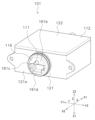
- FIG. 15 is a perspective view of the locking device 1.
- the locking device 1 includes a locking pin 111, a housing 112 through which the locking pin 111 is inserted, and a detection member 116 movably supported on the housing 112.
- the housing 112 has a first housing portion 121 and a second housing portion 122.
- the first housing portion 121 is box-shaped with one side open.
- the first housing portion 121 is open on the side facing the Z2 direction.
- the second housing portion 122 is plate-shaped and is positioned so as to cover the opening of the first housing portion 121.
- the connector portion for electrically connecting the locking device 101 to the vehicle controller is omitted.
- Figure 16 is a perspective view of the locking device 101 with the second housing portion 122 removed, viewed from the Z2 direction.
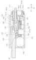
- Figure 17 is a cross-sectional view of the locking device 101 between B and B in Figure 16.
- the locking device 101 has the lock pin 111 described above, the housing 112 described above, a drive unit 113, a lock detection unit 114, an emergency cable 115, a detection member 116, a biasing member 118, and a movement detection unit 119.
- the housing 112 houses the drive unit 113, the lock detection unit 114, and the movement detection unit 119.
- the lock pin 111 can move in the X direction from a lock position P1, which restricts the movement of the object, to an unlock position P2, which releases the restriction on the movement of the object.
- the drive unit 113 moves the lock pin 111 in the X direction between the lock position P1 and the unlock position P2.
- the lock detection unit 114 detects the movement of the lock pin 111 to the lock position P1.
- the emergency cable 115 is provided to be pulled by the operator to move the lock pin 111 from the lock position P1 to the unlock position P2 and release the lock.
- the detection member 116 is provided to detect damage to the engagement claw 821 of the charging connector 800.
- the movement detection unit 119 detects that the detection member 116 has moved to the push-in position Q1.
- the first transmission gear 131 is fixed to the output shaft 130a.
- the first transmission gear 131 rotates together with the rotation of the output shaft 130a.
- the first transmission gear 131 is a helical gear.
- the second transmission gear 132 meshes with the first transmission gear 131.
- the second transmission gear 132 is rotatably supported by the housing 112.
- the rotation axis of the second transmission gear 132 is parallel to the Z direction.
- the second transmission gear 132 is a helical gear.
- the second transmission gear 132 is disposed on the X2 direction side of the first transmission gear 131.
- the third transmission gear 133 is arranged coaxially with the second transmission gear 132.
- the third transmission gear 133 is rotatably supported by the housing 112.
- the third transmission gear 133 is a helical gear.
- the third transmission gear 133 is arranged on the Z2 direction side of the second transmission gear 132.
- the third transmission gear 133 is connected to the second transmission gear 132.
- the third transmission gear 133 rotates together with the rotation of the second transmission gear 132.
- the fourth transmission gear 134 meshes with the third transmission gear 133.
- the fourth transmission gear 134 is rotatably supported by the housing 112.
- the fourth transmission gear 134 is disposed on the X2 direction side of the third transmission gear 133.
- the rack member 136 has a main body 141, a switch pressing portion 142 (second operating portion), and a rack gear 143.
- the main body 141 is supported by the housing 12 so as to be movable in the X direction.
- the main body 141 fits onto the end 111a of the lock pin 111 as shown in FIG. 17.
- the switch pressing portion 142 protrudes from the main body 141 in the Y1 direction as shown in FIG. 16.
- the switch pressing portion 142 presses the lock detection switch 114a of the lock detection portion 114.
- the lock detection portion 114 is fixed to the second housing portion 122.
- the lock detection portion 114 is disposed on the Y1 side of the switch pressing portion 142.
- the lock detection portion 114 has a lock detection switch 114a.
- the lock detection switch 114a is disposed facing in the Y2 direction.
- FIG. 18A is a diagram showing the state in which the lock pin 111 is disposed in the unlocked position P2 and the detection member 116 is disposed in the non-pushed-in position Q2.
- FIG. 18A is a diagram showing the drive unit 113, the lock detection unit 114, the detection member 116, and the movement detection unit 119 as viewed from the Z2 direction side.
- FIG. 18B is a diagram showing the state in which the lock pin 111 is disposed in the locked position P1 and the detection member 116 is disposed in the pushed-in position Q1 from the state shown in FIG. 18A.
- the emergency cable 115 is engaged with the rack member 136.
- the emergency cable 115 extends outside the housing 112.
- the rack member 136 can be moved in the X1 direction. This moves the lock pin 111, which is disposed in the locked position P1, in the X1 direction, and moves the lock pin 111 to the unlocked position P2.
- the detection member 116 has a main body 161, a restricting portion 162, and a switch pressing portion 163 (first operation portion).
- the main body 161 has a shape extending in the X direction.
- the main body 161 is, for example, cylindrical.
- the main body 161 is inserted movably in the X direction into a through hole 121c (moving member insertion hole) provided in a side wall 121a on the X2 direction side of the first housing portion 121.
- a through hole 121c moving member insertion hole
- the main body 161 has a through hole 161a (locking member insertion hole) formed along the X direction, and the lock pin 111 is inserted into this through hole movably in the X direction.
- the main body 161 has an outer surface 161b on the X2 direction side.
- a recess 161c recessed toward the X1 direction side is formed in the outer surface 161b.
- the engaging claw 821 of the charging connector 800 comes into contact with an abutment portion 161d of the outer surface 161b on the opposite side of the lock pin 111 with the recess 161c therebetween, and the main body 161 is pushed in the X1 direction (see FIG. 13).
- FIG. 19(a) is a perspective view showing the vicinity of the rotating part 820 of the charging connector 800.
- the rotating part 820 has an engagement claw 821 and a claw support part 822 at the tip side.
- the claw support part 822 supports the engagement claw 821.
- the claw support part 822 is connected to the claw operation part 830.
- the engagement claw 821 is arranged on the insertion part 810 side of the claw support part 822.
- the claw support part 822 is formed in an approximately T-shape
- the engagement claw 821 is arranged at the lower end of the T of the claw support part 822, and the rotating part 820 as a whole is also formed in an approximately T-shape.
- the above-mentioned recess 161c is formed in a shape that allows the claw support part 822 of the rotating part 820 to be inserted.
- the recess 161c is formed in an approximately T-shape when viewed along the X direction corresponding to the claw support part 822.
- the recess 161c may have any shape that allows the claw support portion 822 to fit into, and is not limited to the approximate T-shape of this embodiment.
- the rotating portion 820 is also not limited to the approximate T-shape.
- Figure 19 (b) is a perspective view showing the state in which the detection member 116 is pushed in the X1 direction by the engagement claw 821.
- the engagement claw 821 abuts against the abutment portion 161d, and the claw support portion 822 faces the recess 161c.
- the engaging claw 821 is damaged, there is no part of the rotating part 820 that abuts against the abutting part 161d, and as shown in FIG. 14, the claw support part 822 fits into the recess 161c, so the detection member 116 including the main body part 161 is not pushed in the X1 direction.
- the detection member 116 has the recess 161c, the detection member 116 cannot be pushed in by the claw support portion 822 alone, so even if only the engagement claw 821 of the rotating portion 820 that abuts against the engagement protrusion 740 is damaged, it can be determined that the engagement claw 821 is damaged.
- the restricting portion 162 is disposed inside the housing 12, at the end of the main body portion 161 on the X1 direction side.
- the restricting portion 162 protrudes outward from the outer periphery of the main body portion 161.
- the restricting portion 162 is formed in an annular shape, but the shape is not particularly limited as long as it can restrict the detection member 116 from coming out of the housing 112.
- the biasing member 118 shown in FIG. 17 biases the detection member 116 toward the X2 direction, and the restricting portion 162 abuts against the side wall 121a to restrict the detection member 116 from coming out of the housing 112.
- the biasing member 118 is, for example, a coil spring.
- the X1 direction end of the biasing member 118 abuts against the protruding wall 123 that protrudes toward the Z2 direction from the bottom surface 121b of the first housing portion 121.
- the X2 direction end of the biasing member 118 abuts against the main body portion 161 of the detection member 116.
- the biasing member 118 biases the detection member 116 toward the non-pushed position Q2.
- FIG. 16 and FIG. 17 show the state in which the detection member 116 is disposed in the pushed-in position Q1.
- the switch pressing portion 163 protrudes from the regulating portion 162 in the Y1 direction.
- the switch pressing portion 163 is generally plate-shaped.
- the switch pressing portion 163 presses the movement detection switch 119a of the movement detection portion 119.
- the switch pressing portion 163 has an inclined portion at the end on the X1 direction side so as to gradually press the movement detection switch 119a as it moves in the X1 direction.
- the inclined portion is inclined so as to move toward the Y2 direction as it moves in the X1 direction.
- the movement detection unit 119 detects the movement of the detection member 116.
- the movement detection unit 119 is fixed to a bottom surface 121b of the first housing part 121.
- the movement detection unit 119 is disposed on the Y1 direction side of the detection member 116.
- the movement detection unit 119 has a movement detection switch 119a (moving member detection switch).
- the movement detection switch 119a is disposed facing the Y2 direction side.
- the detection member 116 is pushed in the X1 direction by the engagement claw 821 and moves to the pushed-in position Q1.
- the movement detection switch 119a is pressed by the switch pressing portion 163 of the detection member 116. This indicates that the engagement claw 821 is not damaged.
- the movement detection switch 119a is not pressed when the charging connector 800 is inserted into the inlet 720, it can be determined that the engagement claw 821 is damaged because the detection member 116 is not pushed in.
- the movement direction of the detection member 116 is parallel to the movement direction of the lock pin 111.
- lock detection switch 114a and the movement detection switch 119a are directly connected in the same way as in embodiment 1, and the controller 81 determines whether the switch is on or off in the same way as in embodiment 1, so a description thereof will be omitted.
- control operation at the start of charging in embodiment 2 is also the same as in embodiment 1, so a description thereof will be omitted.
- Both the lock detector 114 that detects the movement of the lock pin 111 and the movement detector 119 that detects damage to the engagement claw 821 are provided in the lock device 101 and not in the inlet 720, so that the wiring for detection comes only from the lock device 101 side, simplifying the wiring. In addition, because there is no longer any wiring for detection from the inlet 720 side, there is no need to consider interference with other components, and the freedom of vehicle body design can be improved.
- the movement detection switch 119a is pressed by the switch pressing portion 163, so that the engagement claw 821 can detect that the detection member 116 has moved, and it can be determined that the engagement claw 821 is not damaged.
- the wiring can be made simpler than if the movement detection switch 119a and the lock detection switch 114a each output an on or off signal.
- control can be made simpler than if the detection results were input separately from each of the movement detection switch 119a and the lock detection switch 114a.
- the lock pin 111 and the detection member 116 are integrated into the lock device 1, so compared to when the detection member is inside the inlet 720, for example, the positional relationship between the lock pin 111 and the detection member 116 is not subject to misalignment due to dimensional errors, and positioning during assembly is also simple.
- the first transmission gear 31, the second transmission gear 32, the third transmission gear 33, the fourth transmission gear 34, and the fifth transmission gear 35 are provided, but the configuration is not limited to this. It is sufficient that the rack member 36 can be moved by the driving force of the motor 30.
- the first transmission gear 131, the second transmission gear 132, the third transmission gear 133, and the fourth transmission gear 134 are provided, but the configuration is not limited to this. It is sufficient that the rack member 136 can be moved by the driving force of the motor 130.
- lock pin 11 moves in the vertical direction and the detection pin 16 moves horizontally, but this is not limited to the above.
- the lock pin 11 may move horizontally and the detection pin 16 may move in the vertical direction, or both the lock pin 11 and the detection pin 16 may move in the same plane.
- a lock abnormality signal and a charging connector abnormality signal are output to the display, and the lock abnormality or charging connector abnormality is displayed on the display.
- the lock abnormality or charging connector abnormality may be notified to the operator by sound, light, or the like.
- the state of each switch is determined to be on by pressing the lock detection switch and the movement detection switch with the switch pressing portion.
- the on state may be determined by the switch pressing portion coming into contact with the lock detection switch and the movement detection switch.
- the locking device of the present invention has the effect of simplifying wiring and is useful as a device for locking power supply cables in plug-in hybrid vehicles, electric vehicles, etc.
- Locking device 11 Lock pin 13: Driving section 14: Lock detection section 16: Detection pin 19: Movement detection section 520: Inlet 600: Charging connector 614: Tip section
Landscapes
- Engineering & Computer Science (AREA)
- Power Engineering (AREA)
- Transportation (AREA)
- Mechanical Engineering (AREA)
- Details Of Connecting Devices For Male And Female Coupling (AREA)
- Charge And Discharge Circuits For Batteries Or The Like (AREA)
- Electric Propulsion And Braking For Vehicles (AREA)
Abstract
ロック装置は、ロックピンと、駆動部と、検知ピンと、ロック検知部と、移動検知部と、を備える。ロックピンは、充電用インレットに差し込まれた充電コネクタの先端部分が、インレットの挿入孔と係合した係合状態から非係合状態に移動することを規制するロック位置と、先端部分の移動の規制を解除するアンロック位置の間を移動可能である。駆動部は、ロックピンをロック位置とアンロック位置の間で移動させる。検知ピンは、充電コネクタのインレットへの差し込みの際に先端部分によって押し込み位置に移動する。ロック検知部は、ロックピンのロック位置への移動を検知する。移動検知部は、検知ピンの押し込み位置への移動を検知する。このような構造により、配線を簡素化することが可能なロック装置を提供することができる。
Description
本発明は、ロック装置に関する。
近年、電気自動車やプラグインハイブリッド車などの普及が進んでいる。これらの車両では、バッテリの残量が減ると充電施設においてバッテリの充電が行われる。
バッテリの充電は、充電施設から延びる給電ケーブルを車体の給電口(インレット)に接続することによって行われる(例えば、特許文献1参照。)。
特許文献1に示す車両用充電インレットには、車両充電中に充電コネクタがインレットから抜けないようにロックするロック装置が設けられている。充電コネクタをインレットに差し込むとロック装置が作動し、ロックピンが充電コネクタの係合部(穴部)に挿入され、ロック位置に移動する。これによって充電コネクタのインレットからの抜けが防止される。
ここで、充電コネクタの係合部が
破損していた場合、ロックピンがロック位置にあっても充電コネクタをインレットから抜くことが可能な状態となる。そのため、特許文献1に示す車両用充電インレットでは、ロックピンの動作を検知する検知部と充電コネクタの故障を検知する検知部の双方がオンの状態でなければ充電を開始しないように構成されている。
破損していた場合、ロックピンがロック位置にあっても充電コネクタをインレットから抜くことが可能な状態となる。そのため、特許文献1に示す車両用充電インレットでは、ロックピンの動作を検知する検知部と充電コネクタの故障を検知する検知部の双方がオンの状態でなければ充電を開始しないように構成されている。
しかしながら、特許文献1の示す車両用充電コネクタでは、充電コネクタの故障を検知する検知部がインレット側に配置され、ロックピンの動作を検知する検知部がインレット外のアクチュエータ側に配置されており、配線が複雑になっていた。
本発明の目的は、配線を簡素化することが可能なロック装置を提供することである。
本発明の態様にかかるロック装置は、ロック部材と、駆動部と、移動部材と、ロック検知部と、移動部材検知部と、を備える。ロック部材は、充電用インレットに差し込まれた充電コネクタの係合部が、インレットの被係合部と係合した係合状態から非係合状態に移動することを規制するロック位置と、係合部の移動の規制を解除するアンロック位置の間を移動可能である。駆動部は、ロック部材をロック位置とアンロック位置の間で移動させる。移動部材は、充電コネクタのインレットへの差し込みの際に係合部によって所定位置に移動する。ロック検知部は、ロック部材のロック位置への移動を検知する。移動部材検知部は、移動部材の所定位置への移動を検知する。
本発明によれば、配線を簡素化することが可能なロック装置を提供することができる。
以下、本発明にかかる実施形態のロック装置について図面を参照しながら説明する。
本実施形態のロック装置は、車体の給電口に接続した充電コネクタ(対象物の一例)をロックするために用いることができる。ロック装置は、一般的に車体の給電口付近に設けられているが、充電コネクタをロックし、充電コネクタが車体の給電口から脱落を防止することが可能であれば、その配置場所が限定されるものではない。ロック装置は、充電コネクタが車体の給電口から脱落を防止できるのであれば、充電コネクタ自体をロックするものでなくてもよく、充電コネクタに連結している部材をロックしてもよい。詳しくは後述するが、ロック装置はロックピンを突出させ、充電コネクタの移動を規制することによって、充電コネクタが給電口(インレット)から取り外されることを防止する。なお、ロック装置は、フューエルリッドのロック装置などの、ピンの前進により対象物の移動を抑制するロック装置として用いることもできる。
(実施形態1)
(ロック装置1の概要)
図1は、実施形態1のロック装置1が配置された車両500の一部および充電コネクタ600を示す斜視図である。図2は、充電コネクタ600が車両500のインレット520に差し込まれた状態を示す側面模式図である。図2に示すように、例えば駆動源としてバッテリを備えた車両500には、外部電源によって車両500のバッテリを充電可能な充電システムが搭載されている。車両500の側面501には、インレット520が配置されている。
(ロック装置1の概要)
図1は、実施形態1のロック装置1が配置された車両500の一部および充電コネクタ600を示す斜視図である。図2は、充電コネクタ600が車両500のインレット520に差し込まれた状態を示す側面模式図である。図2に示すように、例えば駆動源としてバッテリを備えた車両500には、外部電源によって車両500のバッテリを充電可能な充電システムが搭載されている。車両500の側面501には、インレット520が配置されている。
図3は、実施形態1のロック装置1が配置された車両の一部および充電コネクタを車両側から視た斜視図である。側面501は二点鎖線で示し、図において側面501の奥側の構成を実線で描いている。
充電コネクタ600は、インレット520に差し込まれる挿入部610を有する。挿入部610は、インレット520と電気的に接続されるコネクタ側接続部611と、コネクタ側接続部611を囲むように配置された突起部612(係合部)と、を有する。
インレット520は、図1および図2に示すように、インレット側接続部521と、挿入孔522(被係合部)と、を有する。充電コネクタ600がインレット520に差し込まれた状態において、インレット側接続部521は、コネクタ側接続部611と電気的に接続される。充電コネクタ600がインレット520に差し込まれた状態において、挿入孔522に突起部612が挿入される。
図2および図3に示すように、車両500のインレット520の上方には、ロック装置1が配置されている。ロック装置1は、一例として、そのロックピン11が上下方向に沿って移動するように配置されている。ロック装置1の配置は、これに限らず、ロックする対象物に合わせて場所および姿勢を適宜変更すればよい。
給電する際に、充電コネクタ600が、インレット520に挿入されると、ロックピン11は、突起部612の一部に設けられたロック孔613に挿入される。ロックピン11がロック孔613に挿入された状態では、突起部612が、挿入孔522から抜けることが防止される。このように、挿入孔522に挿入された状態(係合状態)から、挿入孔522から抜けた状態(非係合状態)への突起部612の移動を規制するロックピン11の位置がロック位置P1として示されている。
また、充電コネクタ600をインレット520から取り外す際には、ロックピン11は、上方向に移動し、ロック孔613から抜去される。このように、挿入孔522に挿入された状態(係合状態)から、挿入孔522から抜けた状態(非係合状態)への突起部612の移動の規制を解除するロックピン11の位置がアンロック位置P2(二点鎖線)として示されている。
ここで、突起部612のうち、インレット520への挿入方向におけるロック孔613を含む先端部分614(当接部分)が欠損している場合、ロックピン11がロック位置P1に配置されている状態であっても充電コネクタ600をインレット520から抜くことができるため好ましくない。そのため、ロック装置1には、先端部分614の破損を検出する検知ピン16(移動部材)が設けられている。検知ピン16は、インレット520に形成された貫通孔523に挿通されている。貫通孔523は、インレット520の挿入孔522の底部にインレット520の挿入孔522とは反対の外側まで貫通するように形成されている。貫通孔523は、後述するX方向に沿って形成されている。検知ピン16は、インレット520の挿入孔522とは反対の外側からインレット520の挿入孔522の底部に設けられた貫通孔523に向かって突出している。
図2に示すように、充電コネクタ600がインレット520に差し込まれると、充電コネクタ600の先端部分614が検知ピン16を移動させる。検知ピン16が先端部分614によって押し込まれた位置が、押し込み位置Q1(所定位置)として示されている。
一方、充電コネクタ600の先端部分614が破損している場合は、図4に示すように、充電コネクタ600をインレット520に差し込んだ場合でも、先端部分614によって押すことができないため、検知ピン16が移動しない。検知ピン16が押し込まれていない位置を非押し込み位置Q2として示されている。このように、充電コネクタ600をインレット520に差し込んだ場合でも検知ピン16が非押し込み位置Q2から押し込み位置Q1に移動しないことによって先端部分614の破損を検出することができる。
(ロック装置1の構成)
次に、ロック装置1について説明する。ロック装置1のロックピン11の移動方向をZ方向とし、Z方向のうちアンロック位置P2からロック位置P1への移動方向をZ1とし、ロック位置P1からアンロック位置P2への移動方向をZ2とする。検知ピン16の移動方向をX方向とし、X方向のうち検知ピン16(移動部材)が先端部分614によって押し込まれる方向をX1とし、X1方向の反対をX2方向とする。X方向はZ方向に対して垂直な方向である。X1方向は、インレット520に充電コネクタ600を差し込む方向ともいえ、X2方向は、インレット520から充電コネクタ600を引き抜く方向ともいえる。また、Z方向およびX方向に垂直な方向をY方向とする。Y方向は、図2における紙面に垂直な方向である。Y方向のうち図2の紙面手前方向をY1方向とし、図2の紙面奥行き方向をY2方向とする。なお、本明細書で、垂直との記載は、厳密な意味で垂直でなくてもよく、誤差を含むものであり、社会通念上垂直と認識できるものであればよい。また、本明細書で、平行との記載は、厳密な意味で平行でなくてもよく、誤差を含むものであり、社会通念上垂直と認識できるものであればよい。
次に、ロック装置1について説明する。ロック装置1のロックピン11の移動方向をZ方向とし、Z方向のうちアンロック位置P2からロック位置P1への移動方向をZ1とし、ロック位置P1からアンロック位置P2への移動方向をZ2とする。検知ピン16の移動方向をX方向とし、X方向のうち検知ピン16(移動部材)が先端部分614によって押し込まれる方向をX1とし、X1方向の反対をX2方向とする。X方向はZ方向に対して垂直な方向である。X1方向は、インレット520に充電コネクタ600を差し込む方向ともいえ、X2方向は、インレット520から充電コネクタ600を引き抜く方向ともいえる。また、Z方向およびX方向に垂直な方向をY方向とする。Y方向は、図2における紙面に垂直な方向である。Y方向のうち図2の紙面手前方向をY1方向とし、図2の紙面奥行き方向をY2方向とする。なお、本明細書で、垂直との記載は、厳密な意味で垂直でなくてもよく、誤差を含むものであり、社会通念上垂直と認識できるものであればよい。また、本明細書で、平行との記載は、厳密な意味で平行でなくてもよく、誤差を含むものであり、社会通念上垂直と認識できるものであればよい。
図5は、ロック装置1の斜視図である。ロック装置1は、ロックピン11と、ロックピン11が挿通されるハウジング12と、ハウジング12に移動可能に支持された検知ピン16と、を備える。
ハウジング12は、第1ハウジング部21と第2ハウジング部22とを有する。第1ハウジング部21は一面が開口した箱状である。第1ハウジング部21は、Z1方向側の面が開口している。第2ハウジング部22は、板状であり、第1ハウジング部21の開口を塞ぐように配置されている。第2ハウジング部22のX1方向側の面には、車両のコントローラと電気的に接続するためのコネクタ部23が設けられている。
図6は、第1ハウジング部21を取り除いたロック装置1をZ2方向側から視た斜視図である。
ロック装置1は、図5および図6に示すように、上述したロックピン11(ロック部材)と、上述したハウジング12と、駆動部13と、ロック検知部14と、エマージェンシーケーブル15と、検知ピン16(移動部材)と、ピン支持部17と、付勢部材18と、移動検知部19(移動部材検知部)と、出力部20(後述する図10)と、を有する。
ロックピン11は、図2に示すように、対象物の移動を規制するロック位置P1と対象物の移動の規制を解除するアンロック位置P2との間をZ方向に移動可能である。駆動部13は、ロックピン11をロック位置P1とアンロック位置P2との間で移動させる。ロック検知部14は、ロックピン11のロック位置P1への移動を検知する。エマージェンシーケーブル15は、オペレータによって引っ張られてロックピン11をロック位置P1からアンロック位置P2まで移動してロックを解除するために設けられている。検知ピン16は、充電コネクタ600の先端部分614の破損を検知するために設けられている。ピン支持部17は、ハウジング12に検知ピン16をX方向に移動可能に支持する。移動検知部19は、検知ピン16が押し込み位置Q1に移動したことを検知する。出力部20は、ロック検知部14と移動検知部19による検知結果を車両のコントローラ81に出力する。
(駆動部13)
駆動部13は、図6に示すように、モータ30と、第1伝達ギヤ31と、第2伝達ギヤ32と、第3伝達ギヤ33と、第4伝達ギヤ34と、第5伝達ギヤ35と、ラック部材36と、を有する。モータ30は、出力軸30aがY方向に沿うように配置されている。
駆動部13は、図6に示すように、モータ30と、第1伝達ギヤ31と、第2伝達ギヤ32と、第3伝達ギヤ33と、第4伝達ギヤ34と、第5伝達ギヤ35と、ラック部材36と、を有する。モータ30は、出力軸30aがY方向に沿うように配置されている。
第1伝達ギヤ31は、出力軸30aに固定されている。第1伝達ギヤ31は、出力軸30aの回転とともに回転する。第1伝達ギヤ31は、斜歯ギヤである。
第2伝達ギヤ32は、第1伝達ギヤ31と噛み合っている。第2伝達ギヤ32は、回転可能にハウジング12に支持されている。第2伝達ギヤ32の回転軸は、Y方向と平行である。第2伝達ギヤ32は、斜歯ギヤである。第2伝達ギヤ32は、第1伝達ギヤ31のX2方向側に配置されている。
第3伝達ギヤ33は、第2伝達ギヤ32と同軸に配置されている。第3伝達ギヤ33は、回転可能にハウジング12に支持されている。第3伝達ギヤ33は、斜歯ギヤである。第3伝達ギヤ33は、第2伝達ギヤ32よりもハウジング12の外側(Y1方向側)に配置されている。第3伝達ギヤ33は、第2伝達ギヤ32と繋がっている。第3伝達ギヤ33は、第2伝達ギヤ32の回転とともに回転する。
第4伝達ギヤ34は、第3伝達ギヤ33と噛み合っている。第4伝達ギヤ34は、回転可能にハウジング12に支持されている。第4伝達ギヤ34は、第3伝達ギヤ33のモータ30の反対側(X2方向側)に配置されている。
第5伝達ギヤ35は、第4伝達ギヤ34と同軸に配置されている。第5伝達ギヤ35は、回転可能にハウジング12に支持されている。第5伝達ギヤ35は、斜歯ギヤである。第5伝達ギヤ35は、第4伝達ギヤ34よりもハウジング12の内側(Y2方向側)に配置されている。第5伝達ギヤ35は、第4伝達ギヤ34と繋がっている。第5伝達ギヤ35は、第4伝達ギヤ34の回転とともに回転する。
ラック部材36は、第5伝達ギヤ35と噛み合っており、第5伝達ギヤ35の回転によってZ方向に移動する。図7(a)は、ラック部材36、ロックピン11、ロック検知部14、検知ピン16、および移動検知部19を示す斜視図である。図8は、図7(a)をZ1方向側から視た図である。ラック部材36は、ハウジング12の内側において、ロックピン11の端11aと嵌合する。
ラック部材36は、図7および図8(a)に示すように、本体部41と、スイッチ押圧部42(第2操作部)と、ラックギヤ43と、を有する。本体部41は、外形が略直方体状の部材である。スイッチ押圧部42は、図6に示すように、本体部41からY2方向側に突出している。ラック部材36が第5伝達ギヤ35の回転によってZ1方向に移動すると、スイッチ押圧部42よって、ロック検知部14のロック検知スイッチ14aを押圧する。ラックギヤ43は、図6および図7(a)に示すように、本体部41のX1方向側の面に配置されている。ラックギヤ43は、Z方向に沿って配置されている。ラックギヤ43の山部は、Y方向に対して傾斜しており、第5伝達ギヤ35と噛み合っている。
モータ30が駆動して出力軸30aが回転すると、第1伝達ギヤ31が回転する。第1伝達ギヤ31の回転によって、第1伝達ギヤ31と噛み合っている第2伝達ギヤ32が回転する。第2伝達ギヤ32の回転によって、第2伝達ギヤ32と同軸であって繋がっている第3伝達ギヤ33が回転する。第3伝達ギヤ33の回転によって、第3伝達ギヤ33と噛み合っている第4伝達ギヤ34が回転する。第4伝達ギヤ34の回転によって、第4伝達ギヤ34と同軸であって繋がっている第5伝達ギヤ35が回転する。第5伝達ギヤ35の回転によって、ラック部材36がZ方向に移動し、ラック部材36と嵌合しているロックピン11もZ方向に移動する。
(ロック検知部14)
ロック検知部14は、図6に示すように、第2ハウジング部22に固定されている。ロック検知部14は、スイッチ押圧部42と第2ハウジング部22との間に配置されている。ロック検知部14は、ロック検知スイッチ14aを有する。ロック検知スイッチ14aは、Z2方向を向いて配置されている。アンロック位置P2からロック位置P1に向かってラック部材36とともにロックピン11が移動すると、ラック部材36によってロック検知スイッチ14aが押圧される。これによって、ロックピン11がロック位置P1に移動したことを検知できる。
ロック検知部14は、図6に示すように、第2ハウジング部22に固定されている。ロック検知部14は、スイッチ押圧部42と第2ハウジング部22との間に配置されている。ロック検知部14は、ロック検知スイッチ14aを有する。ロック検知スイッチ14aは、Z2方向を向いて配置されている。アンロック位置P2からロック位置P1に向かってラック部材36とともにロックピン11が移動すると、ラック部材36によってロック検知スイッチ14aが押圧される。これによって、ロックピン11がロック位置P1に移動したことを検知できる。
(エマージェンシーケーブル15)
エマージェンシーケーブル15は、ラック部材36に係合している。図3および図6に示すように、エマージェンシーケーブル15は、ハウジング12の外側に延びている。エマージェンシーケーブル15をオペレータがZ2方向に引っ張ることによって、ラック部材36をZ2方向に向かって移動させることができる。これにより、ラック部材36と嵌合しているロックピン11もZ2方向に移動し、ロックピン11をアンロック位置P2に移動させることができる。
エマージェンシーケーブル15は、ラック部材36に係合している。図3および図6に示すように、エマージェンシーケーブル15は、ハウジング12の外側に延びている。エマージェンシーケーブル15をオペレータがZ2方向に引っ張ることによって、ラック部材36をZ2方向に向かって移動させることができる。これにより、ラック部材36と嵌合しているロックピン11もZ2方向に移動し、ロックピン11をアンロック位置P2に移動させることができる。
(検知ピン16、ピン支持部17、付勢部材18)
図9は、ロック装置1の底面図である。図4および図9に示すように、検知ピン16は、X方向に沿って配置されている。検知ピン16は、充電コネクタ600のインレット520への押し込み方向に沿って配置されている。検知ピン16は、第2ハウジング部22の外面22aの外側(Z1方向側)に配置されている。外面22aは、Z1方向に対して垂直であって、Z1方向側を向いている面である。
図9は、ロック装置1の底面図である。図4および図9に示すように、検知ピン16は、X方向に沿って配置されている。検知ピン16は、充電コネクタ600のインレット520への押し込み方向に沿って配置されている。検知ピン16は、第2ハウジング部22の外面22aの外側(Z1方向側)に配置されている。外面22aは、Z1方向に対して垂直であって、Z1方向側を向いている面である。
ピン支持部17は、図5に示すように、検知ピン16をX方向に移動可能にハウジング12に支持する。ピン支持部17は、第1支持部51と、第2支持部52と、を有する。第1支持部51は、外面22aからZ1方向に向かって配置されている。第1支持部51は、一対の第1側壁51aと、第1貫通孔形成壁51bと、を有する。一対の第1側壁51aは、Y方向において対向して配置されている。第1側壁51aの各々は、Y方向に対して垂直に配置されている。第1貫通孔形成壁51bは、一対の第1側壁51aのX2方向側の端の間を繋ぐ。第1貫通孔形成壁51bは、X方向に対して垂直に配置されている。第1貫通孔形成壁51bには、X方向に貫通した貫通孔が形成されている。一対の第1側壁51aのうちY2方向側の第1側壁51aには、切り欠き51cが形成されている。切り欠き51cには、後述する移動検知スイッチ19aが挿入されている。第1貫通孔形成壁51bと外面22aの間には、隙間が形成されている。この隙間には、図5に示すように、後述するスイッチ押圧部63のX1方向側の端63dが挿入可能である。
第2支持部52は、外面22aからZ1方向に向かって配置されている。第2支持部52は、第1支持部51よりもX1方向側に配置されている。第2支持部52は、一対の第2側壁52aと、第2貫通孔形成壁52bと、を有する。一対の第2側壁52aは、Y方向において対向して配置されている。第2側壁52aの各々は、Y方向に対して垂直に配置されている。一対の第2側壁52aは、図9に示すように、一対の第1側壁51aのY方向における外側に配置されている。一対の第2側壁52aは、一対の第1側壁51aのX1方向側の端部と対向するように配置されている。第2貫通孔形成壁52bは、一対の第2側壁52aのX1方向側の端の間を繋ぐ。第2貫通孔形成壁52bは、X方向に対して垂直に配置されている。第2貫通孔形成壁52bは、第1貫通孔形成壁51bとX方向において対向して配置されている。
第1貫通孔形成壁51bの貫通孔と、第2貫通孔形成壁52bの貫通孔にロックピン11が挿入されている。図7(a)および図8では、第1支持部51は省略されている。
検知ピン16は、図8に示すように、ピン本体61と、規制部62と、スイッチ押圧部63(第1操作部)と、を有する。ピン本体61は、X方向に延伸した形状である。ピン本体61は例えば円柱状である。ピン本体61は、第1貫通孔形成壁51bの貫通孔および第2貫通孔形成壁52bの貫通孔に挿入されている。ピン本体61は、X方向に沿って配置されている。図7(b)は、X1方向側から視たピン本体61とロックピン11の配置関係を示す図である。図7(b)に示すように、ロックピン11がロック位置P1に配置されている状態において、X方向に沿って視てピン本体61はロックピン11と重なっている。
規制部62は、図7(a)に示すように、ピン本体61に配置されている。規制部62は、図5に示すように、第1貫通孔形成壁51bと第2貫通孔形成壁52bの間に配置されている。規制部62は、ピン本体61から外面22a側方向(Z2方向)に延びる。規制部62は、図9に示すように、一対の第1側壁51aの間に配置されている。
ロック装置1は、検知ピン16を非押し込み位置Q2に向かってX2方向側に付勢する付勢部材18を有する。付勢部材18は、ピン本体61の周囲に配置されている。付勢部材18は、例えばコイルバネである。付勢部材18は、図5に示すように、規制部62と第2支持部52の間に配置されている。付勢部材18は、X2方向側の端が規制部62に当接し、X1方向側の端が第2支持部52に当接する。規制部62は、付勢部材18によってX2方向側に向かって付勢されているが、第1支持部51の第1貫通孔形成壁51bに当接することによってX2方向側への移動が規制される。このように、付勢部材18によって規制部62とともにピン本体61もX2方向側に付勢されているため、検知ピン16は非押し込み位置Q2に向かって付勢されている。
スイッチ押圧部63は、図8に示すように、規制部62の外面22a側(Z2方向側)に配置されている。スイッチ押圧部63は、略板状である。スイッチ押圧部63は、外面22aと対向して配置されている。スイッチ押圧部63は、規制部62とともに、第1貫通孔形成壁51bと第2貫通孔形成壁52bの間に配置されている。スイッチ押圧部63は、規制部62とともに一対の第1側壁51aの間に配置されている。スイッチ押圧部63は、Y2方向側の端に押圧面63aを有する。押圧面63aは、移動検知部19の移動検知スイッチ19aを押圧する。押圧面63aは、X1方向への移動に伴って移動検知スイッチ19aを徐々に押圧するようにX2方向側の端に傾斜面を有する。傾斜面は、X2方向に向かうに従ってY1方向側に向かうように傾斜している。スイッチ押圧部63は、規制部62からX2方向側に突出した端63dを有する。規制部62が第1貫通孔形成壁51bに当接した状態において、端63dは、図5に示すように、第1貫通孔形成壁51bと外面22aとの間の隙間に挿入される。
(移動検知部19)
移動検知部19は、検知ピン16の移動を検知する。移動検知部19は、図5に示すように、外面22aに固定されている。移動検知部19は、一対の第1側壁51aのY2方向側に配置されている。移動検知部19は、移動検知スイッチ19a(移動部材検知スイッチ)を有する。移動検知スイッチ19aは、Y1方向側に向かって切り欠き51cからピン本体61側に向かって突出して配置されている。
移動検知部19は、検知ピン16の移動を検知する。移動検知部19は、図5に示すように、外面22aに固定されている。移動検知部19は、一対の第1側壁51aのY2方向側に配置されている。移動検知部19は、移動検知スイッチ19a(移動部材検知スイッチ)を有する。移動検知スイッチ19aは、Y1方向側に向かって切り欠き51cからピン本体61側に向かって突出して配置されている。
ピン本体61がX1方向側に移動すると、移動検知スイッチ19aがスイッチ押圧部63の押圧面63aに押され、移動検知スイッチ19aが押圧された状態となる。図9は、スイッチ押圧部63が移動検知スイッチ19aに当接し、移動検知スイッチ19aが押圧された状態を示す。図9では、検知ピン16が押し込み位置Q1に配置された状態が実線で示され、非押し込み位置Q2に配置された状態が二点鎖線で示されている。
図2に示すように、充電コネクタ600がインレット520に挿入されると、先端部分614が破損していない場合、先端部分614によって検知ピン16がX1方向に押されて、押し込み位置Q1に移動する。押し込み位置Q1に移動すると、検知ピン16のスイッチ押圧部63によって移動検知スイッチ19aが押圧される。これによって先端部分614が破損していないことがわかる。一方、充電コネクタ600がインレット520に挿入された際に移動検知スイッチ19aが押圧されない場合、検知ピン16が押し込まれていないため、先端部分614が破損していると判断することができる。
(出力部20)
図10(a)は、ロック検知スイッチ14aと、移動検知スイッチ19aの電気的な接続を示す図である。ロック検知スイッチ14aと移動検知スイッチ19aは電気的に直列接続されている。出力部20は、第1端子71と、第2端子72と、を有する。出力部20は、コネクタ部23に設けられている。出力部20から車両のコントローラ81に信号が出力される。
図10(a)は、ロック検知スイッチ14aと、移動検知スイッチ19aの電気的な接続を示す図である。ロック検知スイッチ14aと移動検知スイッチ19aは電気的に直列接続されている。出力部20は、第1端子71と、第2端子72と、を有する。出力部20は、コネクタ部23に設けられている。出力部20から車両のコントローラ81に信号が出力される。
第1端子71は、ロック検知スイッチ14aの一方の端子と接続されている。ロック検知スイッチ14aの他方の端子は、第1抵抗73の一方の端子と接続されている。第1抵抗73の他方の端子は、移動検知スイッチ19aの一方の端子と接続されている。移動検知スイッチ19aの他方の端子は、第2端子72と接続されている。第2抵抗74は、移動検知スイッチ19aと並列に配置されている。第2抵抗74の一方の端子は、第1抵抗73の他方の端子と接続されており、第2抵抗74の他方の端子は、第2端子72に接続されている。
図10(a)では、ロック検知スイッチ14aは押圧された状態(オン状態)であり、移動検知スイッチ19aは押圧された状態(オン状態)である。第1抵抗73の抵抗値をR1(Ω)とし、第2抵抗74の抵抗値をR2(Ω)とし、第1端子71から第2端子72にI(A)の電流を流すと、図10(a)の状態では、第2抵抗74側ではなく移動検知スイッチ19a側に電気が流れるため、第1端子71と第2端子72の間には、I×R1(V)の電圧が生じる。I×R1(V)の電圧を第1電圧値とする。
図10(b)では、ロック検知スイッチ14aは押圧された状態(オン状態)であり、移動検知スイッチ19aは押圧されていない状態(オフ状態)である。この場合、移動検知スイッチ19a側には電気が流れず、第2抵抗74側に電気が流れるため、第1端子71と第2端子72の間にはI×(R1+R2)(V)の電圧が生じる。I×(R1+R2)(V)の電圧を第2電圧値とする。また、ロック検知スイッチ14aが押圧されていない状態(オフ状態)では、第1端子71から第2端子72に電流を流しても、電圧が生じず、0(V)となる。この0(V)を第3電圧値とする。
このように、第1端子71と第2端子72には、同一の電流であってもロック検知スイッチ14aと移動検知スイッチ19aの状態によって、0ボルトも含めた3種類の異なる第1電圧から第3電圧値が出力される。
これらの電圧値(信号)は、車両500に設けられているコントローラ81に入力される。コントローラ81は、プロセッサと、記憶装置を含む。プロセッサは、例えばCPU(Central Processing Unit)である。プロセッサは、記憶装置に記憶されているプログラムに従って車両の充電の制御のための処理を実行する。記憶装置は、ROM(Read Only Memory)のような不揮発性メモリおよびRAM(Random Access Memory)のような揮発性メモリを含む。記憶装置は、ハードディスク、あるいはSSD(Solid State Drive)などの補助記憶装置を含んでいてもよい。記憶装置は、非一時的な(non-transitory)コンピュータで読取り可能な記録媒体の一例である。コントローラ81は、取得したデータに基づいて、車両500を制御するための信号を出力する。
コントローラ81は、第1電圧と第2電圧の間の値となる第1閾値と、第1電圧と第3電圧の間の値となる第2閾値を記憶している。コントローラ81は、第1端子71と第2端子72の間に印加される電圧と、第1閾値および第2閾値を比較することによって、第1電圧値と第2電圧値と第3電圧値のいずれが第1端子71と第2端子72の間に出力されているかを判断し、ロック検知スイッチ14aのオン・オフ状態と移動検知スイッチ19aのオン・オフ状態を判断することができる。
第1端子71と第2端子72の間に第2電圧値が出力されていると判断した場合、コントローラ81は、ロック検知スイッチ14aがオン状態であり、移動検知スイッチ19aがオフ状態であると判断できる。これにより、コントローラ81は、ロックピン11はロック位置P1に移動しているが、先端部分614が破損しており、充電コネクタ600がロックできていない状態である可能性があると判断できる。
第1端子71と第2端子72の間に第1電圧値が出力されていると判断した場合、コントローラ81は、ロック検知スイッチ14aがオン状態であり、移動検知スイッチ19aがオン状態であると判断できる。これにより、コントローラ81は、ロックピン11はロック位置P1に移動し、先端部分614も正常であるため、充電コネクタ600がロックされていると判断できる。
第1端子71と第2端子72の間に第3電圧値が出力されていると判断した場合、コントローラ81は、ロック検知スイッチ14aがオフ状態であると判断できる。これにより、ロックピン11がロック位置P1に移動しておらず、充電コネクタ600はロックピン11によるロック状態ではないと判断できる。
コントローラ81には、接続検知部82からの信号が入力される。充電コネクタ600の信号端子とインレット520の信号端子が接続されて構成された信号線のうち1本が充電コネクタ600のインレット520への接続検知用に利用されている。このため、充電コネクタ600とインレット520の互いに対応する信号端子が接続検知部82を構成する。充電コネクタ600がインレット520に接続されると、信号端子同士の導通によってコントローラ81に接続を示す信号が出力される。
(充電開始の際の制御動作)
次に、充電開始の際の制御動作について説明する。図11は、オペレータが充電スタンド側の充電開始の操作をしてから、充電が開始されるまでの車両500側の制御動作を説明するためのフロー図である。
次に、充電開始の際の制御動作について説明する。図11は、オペレータが充電スタンド側の充電開始の操作をしてから、充電が開始されるまでの車両500側の制御動作を説明するためのフロー図である。
はじめに、オペレータが充電コネクタ600をインレット520に挿入し、充電コネクタ600が装備されている充電スタンド側の充電開始ボタンを操作する。
ステップS11において、コントローラ81は、充電コネクタ600とインレット520が接続されたか否かを検知する。オペレータによって充電コネクタ600がインレット520に差し込まれると、接続検知部82からの接続を示す信号がコントローラ81に入力され、コントローラ81は、充電コネクタ600がインレット520に接続されたと判断する。一方、接続を示す信号がコントローラ81に入力されるまで、コントローラ81は、充電開始の際の制御を待機状態とする。
充電コネクタ600がインレット520に接続されたと判断されると、ステップS12において、コントローラ81は、モータ30に駆動信号を出力し、モータ30を所定量駆動する。
次に、ステップS13において、コントローラ81は、ロック検知スイッチ14aがオン状態であるか否かを判定する。ロック検知スイッチ14aがオン状態であると判断した場合、制御はステップS14に進む。具体的には、出力部20からの電圧が第1電圧値または第2電圧値の場合に、コントローラ81は、ロック検知スイッチ14aがオン状態になっていると判断する。これにより、ロックピン11が充電コネクタ600のロック孔613に挿入され、ロック位置P1に配置されていると判断することができる。
一方、ステップS13において、ロック検知スイッチ14aがオン状態ではないと判断した場合、制御はステップS15に進む。ステップS15において、コントローラ81は、例えば充電コネクタ600が設けられた給電装置のディスプレイ、または車両500のディスプレイにロック異常信号を出力する。これにより、ディスプレイが、充電コネクタ600がロックされていない旨の表示を行い、オペレータに報知することができる。
ステップS14において、コントローラ81は、移動検知スイッチ19aがオン状態になっているか否かを判定する。移動検知スイッチ19aがオン状態であると判断した場合、制御はステップS16に進み、ステップS16において、コントローラ81は、車両500の充電を開始する。
一方、ステップS14において、移動検知スイッチ19aがオン状態ではないと判断した場合、制御はステップS17に進む。ステップS17において、コントローラ81は、例えば充電コネクタ600が設けられた給電装置のディスプレイ、または車両500のディスプレイに充電コネクタ異常信号を出力する。これにより、ディスプレイが、充電コネクタ600が破損している旨の表示を行い、オペレータに報知することができる。
(特徴等)
ロックピン11の移動を検知するロック検知部14と先端部分614(係合部)の破損を検知する移動検知部19の双方ともロック装置1に設けられており、インレット520側には設けられていないため、検知のための配線がロック装置1側からのみとなり、配線を簡素化することができる。また、インレット520側からの検知のための配線がなくなったことで、他の部材との干渉を考慮する必要がなく、車体デザインの自由度を向上することができる。
ロックピン11の移動を検知するロック検知部14と先端部分614(係合部)の破損を検知する移動検知部19の双方ともロック装置1に設けられており、インレット520側には設けられていないため、検知のための配線がロック装置1側からのみとなり、配線を簡素化することができる。また、インレット520側からの検知のための配線がなくなったことで、他の部材との干渉を考慮する必要がなく、車体デザインの自由度を向上することができる。
検知ピン16が押し込まれるとスイッチ押圧部63によって移動検知スイッチ19aが押圧されるため、先端部分614によって検知ピン16が移動したことを検知でき、先端部分614が破損していないと判定することができる。
移動検知スイッチ19aとロック検知スイッチ14aを直列接続することにより、移動検知スイッチ19aとロック検知スイッチ14aの各々からオンまたはオフの信号を出力するよりも配線を簡潔にすることができる。また、移動検知スイッチ19aとロック検知スイッチ14aの各々から別々に検知結果が入力されるよりも制御をシンプルにすることができる。
ロックピン11と検知ピン16は、ロック装置1として一体品となっていることから、例えばインレット520内に検知ピンがあるときと比べて、ロックピン11と検知ピン16の位置関係が寸法誤差などで位置ズレすることなく、また、組付け時における位置決めも簡単である。
(実施形態2)
次に、実施形態2のロック装置101について説明する。図12は、実施形態2のロック装置101が配置された車両700の一部および充電コネクタ800を示す斜視図である。図13は、充電コネクタ800が車両700のインレット720に差し込まれた状態を示す側面模式図である。例えば駆動源としてバッテリを備えた車両700には、外部電源によって車両700のバッテリを充電可能な充電システムが搭載されている。図12および図13に示すように、車両700の側面701には、インレット720が配置されている。側面701には、インレット720に隣接して係合爪挿入孔730が形成されている。インレット720の周囲を覆う壁部750には、係合爪挿入孔730に対向するように係合突起740(突起)が配置されている。
次に、実施形態2のロック装置101について説明する。図12は、実施形態2のロック装置101が配置された車両700の一部および充電コネクタ800を示す斜視図である。図13は、充電コネクタ800が車両700のインレット720に差し込まれた状態を示す側面模式図である。例えば駆動源としてバッテリを備えた車両700には、外部電源によって車両700のバッテリを充電可能な充電システムが搭載されている。図12および図13に示すように、車両700の側面701には、インレット720が配置されている。側面701には、インレット720に隣接して係合爪挿入孔730が形成されている。インレット720の周囲を覆う壁部750には、係合爪挿入孔730に対向するように係合突起740(突起)が配置されている。
充電コネクタ800は、挿入部810と、回動部820と、爪操作部830と、を有する。挿入部810は、インレット720に挿入される。回動部820は、挿入部810に隣接して配置されている。回動部820は、係合爪821(爪部)を有する。係合爪821は、回動部820の挿入部810側の部分である。回動部820は、爪操作部830の操作によって回動可能に構成されている。回動部820は、挿入部810に向かう矢印A1方向と、挿入部810から離間する矢印A2方向に回動可能である。回動部820は、例えば、矢印A1方向に向かって図示しない付勢部材によって付勢されている。オペレータによって爪操作部830が押されると、回動部820が矢印A2方向に移動する。
充電コネクタ800をインレット720に差し込む際、挿入部810をインレット720に向かって、回動部820を係合爪挿入孔730に向かって差し込むと、回動部820の係合爪821が係合突起740に当接される。図示しない付勢部材による回動部820の付勢力に逆らって更に差し込むと、係合爪821が係合突起740を乗り越え、係合爪821が係合突起740を係合する。
一方、充電コネクタ800をインレット720から取り外す際には、爪操作部830を抑えることによって、図13に示すように、回動部820が矢印A2方向に回動し係合爪821の係合突起740との係合が解除される(二点鎖線で示す回動部820参照)。これにより、充電コネクタ800をインレット720から取り外すことができる。
本実施形態2のロック装置101は、図12および図13に示すように、係合爪挿入孔730に対向するように配置されている。ロック装置101は、ロックピン111を図13では左右方向に移動させる。
図13では、ロック装置101は、係合爪821が係合突起740に係合した状態において、回動部820の上側のロック位置P1(実線)にロックピン111を移動させる(図13では右方向))ことによって、爪操作部830の操作による回動部820のA2方向への回動を規制する。ロック位置P1では、ロックピン111は、回動部820を挟んで壁部750の反対側に配置されている。充電コネクタ800をインレット720から取り外す際には、ロックピン11をロック位置P1よりも左側のアンロック位置P2(二点鎖線)に移動(図13では左方向)させ、回動部820の回動の規制を解除する。
実施形態1と同様に、係合爪821が破損している場合、ロックピン111がロック位置P1に配置されている状態であっても充電コネクタ800をインレット720から抜くことができるため好ましくない。そのため、ロック装置101には、係合爪821の破損を検出する検知部材116(移動部材の一例)が設けられている。検知部材116は、係合爪挿入孔730に突出している。
図13に示すように、充電コネクタ800がインレット720に差し込まれると、係合爪821が検知部材116をロック装置101側に押し込む。検知部材116が係合爪821によって押し込まれた位置が、押し込み位置Q1として示されている。
一方、充電コネクタ800の係合爪821が破損している場合は、図14に示すように、充電コネクタ800をインレット720に差し込んだ場合でも、係合爪821によって押すことができないため、検知部材116が移動しない。検知部材116が押し込まれていない位置が非押し込み位置Q2として示されている。このように、検知部材116が非押し込み位置Q2から押し込み位置Q1へ移動しないことによって係合爪821の破損を検出することができる。なお、検知部材116と回動部820の形状については後段にて詳述する。
(ロック装置101の構成)
次に、ロック装置101について説明する。図13においてロック装置101のロックピン11の移動方向をX方向とし、X方向のうちアンロック位置P2からロック位置P1への移動方向をX2とし、ロック位置P1からアンロック位置P2への移動方向をX1とする。X方向に対して垂直な方向であって図13の紙面に垂直な方向をY方向とする。Y方向のうち図13の紙面手前方向をY1方向とし、図13の紙面奥行き方向をY2方向とする。X方向とY方向に対して垂直な方向をZ方向とする。Z方向のうち紙面下方向をZ1とし、紙面上方向をZ2とする。
次に、ロック装置101について説明する。図13においてロック装置101のロックピン11の移動方向をX方向とし、X方向のうちアンロック位置P2からロック位置P1への移動方向をX2とし、ロック位置P1からアンロック位置P2への移動方向をX1とする。X方向に対して垂直な方向であって図13の紙面に垂直な方向をY方向とする。Y方向のうち図13の紙面手前方向をY1方向とし、図13の紙面奥行き方向をY2方向とする。X方向とY方向に対して垂直な方向をZ方向とする。Z方向のうち紙面下方向をZ1とし、紙面上方向をZ2とする。
図15は、ロック装置1の斜視図である。ロック装置1は、ロックピン111と、ロックピン111が挿通されるハウジング112と、ハウジング112に移動可能に支持された検知部材116と、を備える。
ハウジング112は、第1ハウジング部121と第2ハウジング部122とを有する。第1ハウジング部121は一面が開口した箱状である。第1ハウジング部121は、Z2方向側の面が開口している。第2ハウジング部122は、板状であり、第1ハウジング部121の開口を塞ぐように配置されている。本実施形態2では、ロック装置101を車両のコントローラと電気的に接続するためのコネクタ部は省略されている。
図16は、第2ハウジング部122を取り除いたロック装置101をZ2方向側から視た斜視図である。図17は、図16のBB間におけるロック装置101の断面図である。
ロック装置101は、図15および図16に示すように、上述したロックピン111と、上述したハウジング112と、駆動部113と、ロック検知部114と、エマージェンシーケーブル115と、検知部材116と、付勢部材118と、移動検知部119と、を有する。ハウジング112は、駆動部113と、ロック検知部114と、移動検知部119と、を収納する。
ロックピン111は、図13に示すように、対象物の移動を規制するロック位置P1から対象物の移動の規制を解除するアンロック位置P2までX方向に沿って移動可能である。駆動部113は、ロックピン111をロック位置P1とアンロック位置P2との間をX方向に沿って移動させる。ロック検知部114は、ロックピン111のロック位置P1への移動を検知する。エマージェンシーケーブル115は、オペレータによって引っ張られ、ロックピン111をロック位置P1からアンロック位置P2まで移動してロックを解除するために設けられている。検知部材116は、充電コネクタ800の係合爪821の破損を検知するために設けられている。移動検知部119は、検知部材116が押し込み位置Q1に移動したことを検知する。
(駆動部113)
駆動部113は、図16に示すように、モータ130と、第1伝達ギヤ131と、第2伝達ギヤ132と、第3伝達ギヤ133と、第4伝達ギヤ134と、ラック部材136と、を有する。モータ130は、出力軸130aがY方向に沿うように配置されている。
駆動部113は、図16に示すように、モータ130と、第1伝達ギヤ131と、第2伝達ギヤ132と、第3伝達ギヤ133と、第4伝達ギヤ134と、ラック部材136と、を有する。モータ130は、出力軸130aがY方向に沿うように配置されている。
第1伝達ギヤ131は、出力軸130aに固定されている。第1伝達ギヤ131は、出力軸130aの回転とともに回転する。第1伝達ギヤ131は、斜歯ギヤである。
第2伝達ギヤ132は、第1伝達ギヤ131と噛み合っている。第2伝達ギヤ132は、回転可能にハウジング112に支持されている。第2伝達ギヤ132の回転軸は、Z方向と平行である。第2伝達ギヤ132は、斜歯ギヤである。第2伝達ギヤ132は、第1伝達ギヤ131のX2方向側に配置されている。
第3伝達ギヤ133は、第2伝達ギヤ132と同軸に配置されている。第3伝達ギヤ133は、回転可能にハウジング112に支持されている。第3伝達ギヤ133は、斜歯ギヤである。第3伝達ギヤ133は、第2伝達ギヤ132のZ2方向側に配置されている。第3伝達ギヤ133は、第2伝達ギヤ132と繋がっている。第3伝達ギヤ133は、第2伝達ギヤ132の回転とともに回転する。
第4伝達ギヤ134は、第3伝達ギヤ133と噛み合っている。第4伝達ギヤ134は、回転可能にハウジング112に支持されている。第4伝達ギヤ134は、第3伝達ギヤ133のX2方向側に配置されている。
ラック部材136は、図16に示すように、本体部141と、スイッチ押圧部142(第2操作部)と、ラックギヤ143と、を有する。本体部141は、X方向に移動可能にハウジング12に支持されている。本体部141は、図17に示すように、ロックピン111の端111aに嵌合する。スイッチ押圧部142は、図16に示すように、本体部141からY1方向側に突出している。ラック部材136が第4伝達ギヤ134の回転によってX2方向に移動すると、スイッチ押圧部142は、ロック検知部114のロック検知スイッチ114aを押圧する。スイッチ押圧部142は、X2方向への移動に伴ってロック検知スイッチ114aを徐々に押圧するために、X2方向側の端に傾斜部を有する。傾斜部は、X2方向に向かうに従ってY2方向側に位置するように傾斜している。ラックギヤ143は、本体部141のY2方向側の面に配置されている。ラックギヤ143は、X方向に沿って配置されている。ラックギヤ43の山部は、Z方向に対して傾斜しており、第4伝達ギヤ134と噛み合っている。
(ロック検知部114)
ロック検知部114は、図16に示すように、第2ハウジング部122に固定されている。ロック検知部114は、スイッチ押圧部142のY1側に配置されている。ロック検知部114は、ロック検知スイッチ114aを有する。ロック検知スイッチ114aは、Y2方向を向いて配置されている。
ロック検知部114は、図16に示すように、第2ハウジング部122に固定されている。ロック検知部114は、スイッチ押圧部142のY1側に配置されている。ロック検知部114は、ロック検知スイッチ114aを有する。ロック検知スイッチ114aは、Y2方向を向いて配置されている。
図18Aは、ロックピン111がアンロック位置P2に配置され、検知部材116が非押し込み位置Q2に配置された状態を示す図である。図18Aは、駆動部113、ロック検知部114,検知部材116、および移動検知部119をZ2方向側から視た図である。図18Bは、図18Aに示す状態からロックピン111がロック位置P1に配置され、検知部材116が押し込み位置Q1に配置された状態を示す図である。
アンロック位置P2からロック位置P1に向かってラック部材136とともにロックピン111が移動すると、ラック部材136のスイッチ押圧部142によってロック検知スイッチ114aが押圧される。これによって、ロックピン111がロック位置P1に移動したことを検知できる。
(エマージェンシーケーブル115)
エマージェンシーケーブル115は、ラック部材136に係合している。エマージェンシーケーブル115は、ハウジング112の外側に延びている。エマージェンシーケーブル15をオペレータがX1方向に引っ張ることによって、ラック部材136をX1方向に向かって移動させることができる。これにより、ロック位置P1に配置されているロックピン111をX1方向に移動し、ロックピン11をアンロック位置P2に移動させることができる。
エマージェンシーケーブル115は、ラック部材136に係合している。エマージェンシーケーブル115は、ハウジング112の外側に延びている。エマージェンシーケーブル15をオペレータがX1方向に引っ張ることによって、ラック部材136をX1方向に向かって移動させることができる。これにより、ロック位置P1に配置されているロックピン111をX1方向に移動し、ロックピン11をアンロック位置P2に移動させることができる。
(検知部材116、付勢部材118)
検知部材116は、図16に示すように、本体部161と、規制部162と、スイッチ押圧部163(第1操作部)と、を有する。本体部161は、X方向に延伸した形状である。本体部161は、例えば円柱状である。本体部161は、図17に示すように、第1ハウジング部121のX2方向側の側壁121aに設けられた貫通孔121c(移動部材挿通孔)に、X方向に移動可能に挿入されている。本体部161には、図17に示すように、X方向に沿って貫通孔161a(ロック部材挿通孔)が形成されており、この貫通孔にロックピン111がX方向に移動可能に挿入されている。本体部161は、図15および図17に示すように、X2方向側に外面161bを有する。外面161bには、X1方向側に向かって凹んだ凹部161cが形成されている。外面161bのうち凹部161cを挟んでロックピン111の反対側の当接部分161dに、充電コネクタ800の係合爪821が当接してX1方向に本体部161は押し込まれる(図13参照)。
検知部材116は、図16に示すように、本体部161と、規制部162と、スイッチ押圧部163(第1操作部)と、を有する。本体部161は、X方向に延伸した形状である。本体部161は、例えば円柱状である。本体部161は、図17に示すように、第1ハウジング部121のX2方向側の側壁121aに設けられた貫通孔121c(移動部材挿通孔)に、X方向に移動可能に挿入されている。本体部161には、図17に示すように、X方向に沿って貫通孔161a(ロック部材挿通孔)が形成されており、この貫通孔にロックピン111がX方向に移動可能に挿入されている。本体部161は、図15および図17に示すように、X2方向側に外面161bを有する。外面161bには、X1方向側に向かって凹んだ凹部161cが形成されている。外面161bのうち凹部161cを挟んでロックピン111の反対側の当接部分161dに、充電コネクタ800の係合爪821が当接してX1方向に本体部161は押し込まれる(図13参照)。
図19(a)は、充電コネクタ800の回動部820近傍を示す斜視図である。図19(a)に示すように、回動部820は、先端側に、係合爪821と、爪支持部822と、を有する。爪支持部822は、係合爪821を支持する。爪支持部822は、爪操作部830と接続されている。係合爪821は、爪支持部822の挿入部810側に配置されている。本実施形態では、例えば、X方向に沿って視て、爪支持部822は略T字形状に形成されており、係合爪821は、爪支持部822のT字の下端に配置されており、回動部820全体としても略T字形状に形成されている。一方、上述した凹部161cは、回動部820のうち爪支持部822が挿入可能な形状に形成されている。本実施形態では、凹部161cは、爪支持部822に対応してX方向に沿って視て略T字形状に形成されている。なお、凹部161cは、爪支持部822が嵌り込むことが可能な形状であればよく、本実施形態のような略T字形状に限られるものではない。また、回動部820も略T字形状に限られるものではない。
図19(b)は、係合爪821によって検知部材116がX1方向に押し込まれている状態を示す斜視図である。係合爪821は当接部分161dに当接し、爪支持部822は凹部161cに対向する。
ここで、係合爪821が破損している場合、回動部820に当接部分161dと当接する部分がなく、図14に示すように、爪支持部822が凹部161cに嵌まり込むため、本体部161を含む検知部材116は、X1方向側に押し込まれない。
このように、検知部材116に凹部161cが設けられていることによって、爪支持部822のみでは検知部材116を押し込むことが出来ないため、回動部820のうち係合突起740と当接する係合爪821のみが破損した場合であっても、係合爪821が破損していると判断することができる。
規制部162は、ハウジング12の内側であって、本体部161のX1方向側の端に配置されている。規制部162は、本体部161の外周から外側に向かって突出している。規制部162は本実施形態では円環状に形成されているが、検知部材116がハウジング112から抜けることを規制できれば、形状は特に限定されない。
図17に示す付勢部材118は、検知部材116をX2方向側に向かって付勢しているが、規制部162が側壁121aに当接することによって、検知部材116がハウジング112から抜けることが規制される。付勢部材118は、例えばコイルバネである。付勢部材118のX1方向側の端は、第1ハウジング部121の底面121bからZ2方向側に向かって突出した突出壁123に当接している。付勢部材118のX2方向側の端は、検知部材116の本体部161に当接している。これによって、付勢部材118は、検知部材116を非押し込み位置Q2に向かって付勢する。なお、図16および図17では、検知部材116が押し込み位置Q1に配置されている状態を示している。
スイッチ押圧部163は、図16に示すように、規制部162からY1方向側に突出している。スイッチ押圧部163は、略板状である。スイッチ押圧部163は、移動検知部119の移動検知スイッチ119aを押圧する。スイッチ押圧部163は、X1方向への移動に伴って移動検知スイッチ119aを徐々に押圧するようにX1方向側の端に傾斜部を有する。傾斜部は、X1方向に向かうに従ってY2方向側に向かうように傾斜している。
(移動検知部119)
移動検知部119は、検知部材116の移動を検知する。移動検知部119は、第1ハウジング部121の底面121bに固定されている。移動検知部119は、検知部材116のY1方向側に配置されている。移動検知部119は、移動検知スイッチ119a(移動部材検知スイッチ)を有する。移動検知スイッチ119aは、Y2方向側に向かって配置されている。
移動検知部119は、検知部材116の移動を検知する。移動検知部119は、第1ハウジング部121の底面121bに固定されている。移動検知部119は、検知部材116のY1方向側に配置されている。移動検知部119は、移動検知スイッチ119a(移動部材検知スイッチ)を有する。移動検知スイッチ119aは、Y2方向側に向かって配置されている。
本体部161が係合爪821に押されて図18Aの状態からX1方向側に移動すると、図18Bに示すように、移動検知スイッチ119aの先端がスイッチ押圧部163によって押圧される。
図13に示すように、充電コネクタ800がインレット720に挿入されると係合爪821が破損していない場合、係合爪821によって検知部材116がX1方向に押されて、押し込み位置Q1に移動する。押し込み位置Q1に移動すると、検知部材116のスイッチ押圧部163によって移動検知スイッチ119aが押圧される。これによって係合爪821が破損していないことがわかる。一方、充電コネクタ800がインレット720に挿入された際に移動検知スイッチ119aが押圧されない場合、検知部材116が押し込まれていないため、係合爪821が破損していると判断することができる。検知部材116の移動方向はロックピン111の移動方向と平行である。
なお、ロック検知スイッチ114aと移動検知スイッチ119aは、実施形態1と同様に直接接続されており、コントローラ81によるスイッチのオンまたはオフの判断も実施形態1と同様であるため、説明を省略する。また、実施形態2における充電開始の際の制御動作も実施形態1と同様であるため、説明を省略する。
(特徴等)
ロックピン111の移動を検知するロック検知部114と係合爪821の破損を検知する移動検知部119の双方ともロック装置101に設けられており、インレット720側には設けられていないため、検知のための配線がロック装置101側からのみとなり、配線を簡素化することができる。また、インレット720側からの検知のための配線がなくなったことで、他の部材との干渉を考慮する必要がなく、車体デザインの自由度を向上することができる。
ロックピン111の移動を検知するロック検知部114と係合爪821の破損を検知する移動検知部119の双方ともロック装置101に設けられており、インレット720側には設けられていないため、検知のための配線がロック装置101側からのみとなり、配線を簡素化することができる。また、インレット720側からの検知のための配線がなくなったことで、他の部材との干渉を考慮する必要がなく、車体デザインの自由度を向上することができる。
検知部材116が押し込まれるとスイッチ押圧部163によって移動検知スイッチ119aが押圧されるため、係合爪821によって検知部材116が移動したことを検知でき、係合爪821が破損していないと判定することができる。
移動検知スイッチ119aとロック検知スイッチ114aを直列接続することにより、移動検知スイッチ119aとロック検知スイッチ114aの各々からオンまたはオフの信号を出力するよりも配線を簡潔にすることができる。また、移動検知スイッチ119aとロック検知スイッチ114aの各々から別々に検知結果が入力されるよりも制御をシンプルにすることができる。
ロックピン111と検知部材116は、ロック装置1として一体品となっていることから、例えばインレット720内に検知部材があるときと比べて、ロックピン111と検知部材116の位置関係が寸法誤差などで位置ズレすることなく、また、組付け時における位置決めも簡単である。
(他の実施の形態)
以上、本開示の一実施の形態について説明したが、本開示は上記実施の形態に限定されるものではなく、本開示の要旨を逸脱しない範囲で種々の変更が可能である。
以上、本開示の一実施の形態について説明したが、本開示は上記実施の形態に限定されるものではなく、本開示の要旨を逸脱しない範囲で種々の変更が可能である。
(A)
上記実施形態1では、第1伝達ギヤ31、第2伝達ギヤ32、第3伝達ギヤ33、第4伝達ギヤ34、および第5伝達ギヤ35が設けられているが、このような構成に限らなくてもよく。モータ30の駆動力によってラック部材36を移動できればよい。上記実施形態2では、第1伝達ギヤ131、第2伝達ギヤ132、第3伝達ギヤ133、および第4伝達ギヤ134が設けられているが、このような構成に限らなくてもよく。モータ130の駆動力によってラック部材136を移動できればよい。
上記実施形態1では、第1伝達ギヤ31、第2伝達ギヤ32、第3伝達ギヤ33、第4伝達ギヤ34、および第5伝達ギヤ35が設けられているが、このような構成に限らなくてもよく。モータ30の駆動力によってラック部材36を移動できればよい。上記実施形態2では、第1伝達ギヤ131、第2伝達ギヤ132、第3伝達ギヤ133、および第4伝達ギヤ134が設けられているが、このような構成に限らなくてもよく。モータ130の駆動力によってラック部材136を移動できればよい。
(B)
上記実施形態1における図では、ロックピン11が上下方向に移動し、検知ピン16が水平に移動しているが、これに限らなくてもよい。例えば、ロックピン11が水平方向に移動し、検知ピン16が上下方向に移動してもよく、また、ロックピン11および検知ピン16の双方が同一平面内で移動してもよい。
上記実施形態1における図では、ロックピン11が上下方向に移動し、検知ピン16が水平に移動しているが、これに限らなくてもよい。例えば、ロックピン11が水平方向に移動し、検知ピン16が上下方向に移動してもよく、また、ロックピン11および検知ピン16の双方が同一平面内で移動してもよい。
(C)
上記実施形態2における図では、ロックピン111および検知部材116は水平方向に移動しているが、これに限らず、例えば上下方向に移動してもよい。
上記実施形態2における図では、ロックピン111および検知部材116は水平方向に移動しているが、これに限らず、例えば上下方向に移動してもよい。
(D)
上記実施形態1,2では、ロック異常信号および充電コネクタ異常信号をディスプレイに出力して、ディスプレイにロック異常または充電コネクタ異常を表示させているが、これに限らず、音または光などでロック異常または充電コネクタ異常をオペレータに報知してもよい。
上記実施形態1,2では、ロック異常信号および充電コネクタ異常信号をディスプレイに出力して、ディスプレイにロック異常または充電コネクタ異常を表示させているが、これに限らず、音または光などでロック異常または充電コネクタ異常をオペレータに報知してもよい。
(E)
上記実施形態1,2では、スイッチ押圧部によってロック検知スイッチおよび移動検知スイッチを押圧することで、各スイッチの状態がオン状態であると判断しているが、これに限らず、例えばスイッチ押圧部がロック検知スイッチおよび移動検知スイッチと接触することによってオン状態であると判断してもよい。
上記実施形態1,2では、スイッチ押圧部によってロック検知スイッチおよび移動検知スイッチを押圧することで、各スイッチの状態がオン状態であると判断しているが、これに限らず、例えばスイッチ押圧部がロック検知スイッチおよび移動検知スイッチと接触することによってオン状態であると判断してもよい。
本発明のロック装置は、配線を簡素化することが可能な効果を有し、プラグインハイブリッド車や電気自動車等の給電ケーブルをロックする装置等として有用である。
1 :ロック装置
11 :ロックピン
13 :駆動部
14 :ロック検知部
16 :検知ピン
19 :移動検知部
520 :インレット
600 :充電コネクタ
614 :先端部分
11 :ロックピン
13 :駆動部
14 :ロック検知部
16 :検知ピン
19 :移動検知部
520 :インレット
600 :充電コネクタ
614 :先端部分
Claims (6)
- 充電用インレットに差し込まれた充電コネクタの係合部が、前記インレットの被係合部と係合した係合状態から非係合状態に移動することを規制するロック位置と、前記係合部の移動の規制を解除するアンロック位置の間を移動可能なロック部材と、
前記ロック部材を前記ロック位置と前記アンロック位置の間で移動させる駆動部と、
前記充電コネクタの前記インレットへの差し込みの際に前記係合部によって所定位置に移動する移動部材と、
前記ロック部材の前記ロック位置への移動を検知するロック検知部と、
前記移動部材の前記所定位置への移動を検知する移動部材検知部と、を備えた、
ロック装置。 - 前記移動部材検知部は、移動部材検知スイッチを有し、
前記移動部材は、前記所定位置へ移動することによって前記移動部材検知スイッチを操作する第1操作部を有する、
請求項1に記載のロック装置。 - 前記ロック検知部は、ロック検知スイッチを有し、
前記ロック部材は、前記アンロック位置から前記ロック位置へ移動することによって前記ロック検知スイッチを操作する第2操作部を有し、
前記移動部材検知スイッチと前記ロック検知スイッチは、直列接続され、
前記充電コネクタが前記インレットに差し込まれた状態において、前記移動部材検知スイッチのオンおよび前記ロック検知スイッチのオンを示す信号、前記移動部材検知スイッチのオフおよび前記ロック検知スイッチのオンを示す信号、または、前記ロック検知スイッチのオフを示す信号のうちいずれか1つの信号を外部に出力する出力部を更に備えた、
請求項2に記載のロック装置。 - 前記ロック部材の移動方向は、前記移動部材の移動方向に対して垂直であり、
前記移動部材の移動方向に沿って視た場合、前記ロック位置における前記ロック部材は、前記移動部材と重なっており、
前記係合部は、前記充電コネクタが前記インレットに差し込まれた状態において、前記移動部材に当接する当接部分を有し、
前記当接部分は、前記充電コネクタが前記インレットに差し込まれ、前記ロック部材が前記ロック位置に移動した状態において、前記ロック部材と前記移動部材の間に配置されている、
請求項1に記載のロック装置。 - 前記ロック部材の移動方向は、前記移動部材の移動方向と平行であり、
前記インレットの被係合部は、突起が形成された壁部を有し、
前記充電コネクタの前記係合部は、前記突起に係合する爪部を有し、
前記ロック部材は、前記充電コネクタが前記インレットに差し込まれた状態において、かつ、前記ロック位置において、前記爪部を挟んで前記壁部の反対側に配置され、
前記移動部材が挿通される移動部材挿通孔が形成され、前記駆動部、前記ロック検知部、および前記移動部材検知部を収納するハウジングを備え、
前記移動部材には、前記ロック部材が挿通されるロック部材挿通孔が形成されている、
請求項1に記載のロック装置。 - 前記ロック部材の移動方向は、前記移動部材の移動方向と平行であり、
前記係合部は、前記充電コネクタが前記インレットに差し込まれた状態において前記移動部材に当接する当接部分を有し、
前記当接部分は、前記充電コネクタが前記インレットに差し込まれた状態において前記移動部材の移動方向に沿って前記移動部材と並んで配置されており、
前記ロック位置において前記ロック部材は、前記移動部材および前記当接部分と、前記移動部材の移動方向に対して垂直な方向に並んで配置されている、
請求項1に記載のロック装置。
Priority Applications (1)
| Application Number | Priority Date | Filing Date | Title |
|---|---|---|---|
| CN202480016929.5A CN120752817A (zh) | 2023-06-15 | 2024-06-13 | 锁定装置 |
Applications Claiming Priority (2)
| Application Number | Priority Date | Filing Date | Title |
|---|---|---|---|
| JP2023098747A JP2024179700A (ja) | 2023-06-15 | 2023-06-15 | ロック装置 |
| JP2023-098747 | 2023-06-15 |
Publications (1)
| Publication Number | Publication Date |
|---|---|
| WO2024257825A1 true WO2024257825A1 (ja) | 2024-12-19 |
Family
ID=93852206
Family Applications (1)
| Application Number | Title | Priority Date | Filing Date |
|---|---|---|---|
| PCT/JP2024/021476 Ceased WO2024257825A1 (ja) | 2023-06-15 | 2024-06-13 | ロック装置 |
Country Status (3)
| Country | Link |
|---|---|
| JP (1) | JP2024179700A (ja) |
| CN (1) | CN120752817A (ja) |
| WO (1) | WO2024257825A1 (ja) |
Citations (4)
| Publication number | Priority date | Publication date | Assignee | Title |
|---|---|---|---|---|
| JP2012019608A (ja) * | 2010-07-08 | 2012-01-26 | Toyota Industries Corp | 自動車充電装置 |
| WO2013061401A1 (ja) * | 2011-10-25 | 2013-05-02 | 住友電装株式会社 | 車両用充電装置 |
| JP2014120231A (ja) * | 2012-12-13 | 2014-06-30 | Tokai Rika Co Ltd | ロック装置 |
| JP2021170859A (ja) * | 2020-04-14 | 2021-10-28 | トヨタ自動車株式会社 | 車両の充電制御装置 |
-
2023
- 2023-06-15 JP JP2023098747A patent/JP2024179700A/ja active Pending
-
2024
- 2024-06-13 CN CN202480016929.5A patent/CN120752817A/zh active Pending
- 2024-06-13 WO PCT/JP2024/021476 patent/WO2024257825A1/ja not_active Ceased
Patent Citations (4)
| Publication number | Priority date | Publication date | Assignee | Title |
|---|---|---|---|---|
| JP2012019608A (ja) * | 2010-07-08 | 2012-01-26 | Toyota Industries Corp | 自動車充電装置 |
| WO2013061401A1 (ja) * | 2011-10-25 | 2013-05-02 | 住友電装株式会社 | 車両用充電装置 |
| JP2014120231A (ja) * | 2012-12-13 | 2014-06-30 | Tokai Rika Co Ltd | ロック装置 |
| JP2021170859A (ja) * | 2020-04-14 | 2021-10-28 | トヨタ自動車株式会社 | 車両の充電制御装置 |
Also Published As
| Publication number | Publication date |
|---|---|
| JP2024179700A (ja) | 2024-12-26 |
| CN120752817A (zh) | 2025-10-03 |
Similar Documents
| Publication | Publication Date | Title |
|---|---|---|
| US9362670B2 (en) | Charge connector locking apparatus | |
| JP6417369B2 (ja) | コネクタ | |
| WO2008035548A1 (en) | Circuit unit housing box | |
| CN102774335B (zh) | 供电控制装置 | |
| US9257772B2 (en) | Electric connector with a lock to retain a terminal within a housing | |
| JP6417370B2 (ja) | コネクタ | |
| JP6401752B2 (ja) | コネクタ | |
| CN103906649A (zh) | 车辆用充电装置 | |
| CN110690625A (zh) | 连接器装置 | |
| JP2008159504A (ja) | コネクタ | |
| US6281444B1 (en) | Protective cover for connector | |
| JP2018067378A (ja) | コネクタ | |
| JP6167343B2 (ja) | 立体駐車場 | |
| JP2024179700A (ja) | ロック装置 | |
| JP5908675B2 (ja) | 車両用制御システム | |
| US20200178407A1 (en) | Electronic apparatus | |
| CN109888696B (zh) | 电气接线箱以及线束 | |
| EP1662618B1 (en) | An electrical connector housing, an electrical connector, and a connector assembly. | |
| CN112969833B (zh) | 锁定装置 | |
| JP6936280B2 (ja) | コネクタ | |
| JP6665539B2 (ja) | サービスプラグを備えた車載用バッテリユニット | |
| JP2006216375A (ja) | コネクタのロック検知方法とコネクタ | |
| JP7746908B2 (ja) | バッテリトレーラ | |
| US20240364043A1 (en) | Connector | |
| JP7693514B2 (ja) | コネクタ |
Legal Events
| Date | Code | Title | Description |
|---|---|---|---|
| 121 | Ep: the epo has been informed by wipo that ep was designated in this application |
Ref document number: 24823440 Country of ref document: EP Kind code of ref document: A1 |
|
| WWE | Wipo information: entry into national phase |
Ref document number: 202480016929.5 Country of ref document: CN |
|
| WWP | Wipo information: published in national office |
Ref document number: 202480016929.5 Country of ref document: CN |
|
| NENP | Non-entry into the national phase |
Ref country code: DE |