WO2024257718A1 - 分析用担体、分析用担体の製造方法、及び分析方法 - Google Patents
分析用担体、分析用担体の製造方法、及び分析方法 Download PDFInfo
- Publication number
- WO2024257718A1 WO2024257718A1 PCT/JP2024/021017 JP2024021017W WO2024257718A1 WO 2024257718 A1 WO2024257718 A1 WO 2024257718A1 JP 2024021017 W JP2024021017 W JP 2024021017W WO 2024257718 A1 WO2024257718 A1 WO 2024257718A1
- Authority
- WO
- WIPO (PCT)
- Prior art keywords
- analytical
- anodized film
- aluminum
- acid
- porous body
- Prior art date
- Legal status (The legal status is an assumption and is not a legal conclusion. Google has not performed a legal analysis and makes no representation as to the accuracy of the status listed.)
- Ceased
Links
Images


Classifications
-
- G—PHYSICS
- G01—MEASURING; TESTING
- G01N—INVESTIGATING OR ANALYSING MATERIALS BY DETERMINING THEIR CHEMICAL OR PHYSICAL PROPERTIES
- G01N33/00—Investigating or analysing materials by specific methods not covered by groups G01N1/00 - G01N31/00
- G01N33/48—Biological material, e.g. blood, urine; Haemocytometers
- G01N33/50—Chemical analysis of biological material, e.g. blood, urine; Testing involving biospecific ligand binding methods; Immunological testing
- G01N33/53—Immunoassay; Biospecific binding assay; Materials therefor
- G01N33/543—Immunoassay; Biospecific binding assay; Materials therefor with an insoluble carrier for immobilising immunochemicals
-
- G—PHYSICS
- G01—MEASURING; TESTING
- G01N—INVESTIGATING OR ANALYSING MATERIALS BY DETERMINING THEIR CHEMICAL OR PHYSICAL PROPERTIES
- G01N33/00—Investigating or analysing materials by specific methods not covered by groups G01N1/00 - G01N31/00
- G01N33/48—Biological material, e.g. blood, urine; Haemocytometers
- G01N33/50—Chemical analysis of biological material, e.g. blood, urine; Testing involving biospecific ligand binding methods; Immunological testing
- G01N33/53—Immunoassay; Biospecific binding assay; Materials therefor
- G01N33/543—Immunoassay; Biospecific binding assay; Materials therefor with an insoluble carrier for immobilising immunochemicals
- G01N33/551—Immunoassay; Biospecific binding assay; Materials therefor with an insoluble carrier for immobilising immunochemicals the carrier being inorganic
- G01N33/553—Metal or metal coated
Definitions
- This disclosure relates to analytical carriers, methods for producing analytical carriers, and analytical methods.
- Immunochromatography is known as one type of analytical method for analyzing an analyte supported on an analytical carrier (see Patent Document 1).
- a lateral flow test kit that uses immunochromatography is also known.
- This test kit includes a test strip on which a capture antibody that reacts with the analyte is fixed to a specific site on the analytical carrier.
- a specimen containing an antigen to be analyzed is collected from a living organism, and a solution containing this specimen is dropped onto a predetermined position on a test strip.
- the antigen then reacts with a labeled antibody that is labeled with particles such as gold colloid particles and latex particles to form a complex.
- the solution containing the complex then flows through the analytical carrier by capillary action.
- the antigen contained in the complex is captured by the capture antibody on the analytical carrier, and the complex gathers at the capture site, causing color development. In this way, the degree of color development at the capture site with the complex supported by the analytical carrier can be visually confirmed to determine whether the specimen contains the antigen.
- a nitrocellulose membrane filter is used as the analytical carrier.
- Nitrocellulose membrane filters generally have a high degree of whiteness, making it relatively easy to visually confirm the test line and control line, and have excellent development performance due to capillary action. For this reason, they are used in many test kits.
- fluorescence measurement is used as a type of analytical method that utilizes immunochromatography.
- the analyte is reacted with an antibody labeled with fluorescent beads to form a complex, and the complex is then reacted with a capture antibody fixed to an analytical carrier.
- the analytical carrier carrying the analyte is irradiated with excitation light of a specific wavelength, and the fluorescence emitted from the fluorescent beads is detected, thereby performing a fluorescent analysis of the analyte.
- the fluorescence emitted from the fluorescent beads bound to the capture antibody and the analyte becomes the signal, and the fluorescence emitted from other sources becomes noise.
- a nitrocellulose membrane filter is used as the analytical carrier, it itself emits high autofluorescence, which is an obstacle to achieving high sensitivity.
- This disclosure has been made in consideration of the problems inherent in the conventional technology.
- the purpose of this disclosure is to provide an analytical carrier capable of suppressing autofluorescence, a method for manufacturing the analytical carrier, and an analytical method using the analytical carrier.
- the analytical support according to the first aspect of the present disclosure is an analytical support including a metal member containing a porous body.
- the porous body includes a skeleton formed by an assembly of a plurality of aluminum particles, and a plurality of voids surrounded by the skeleton.
- the skeleton has an outer shell including an anodized film containing aluminum oxide on the surface of the aluminum particle.
- the porosity of the porous body is 30 volume % or more.
- the average particle size of the plurality of aluminum particles is 0.1 ⁇ m to 20 ⁇ m.
- the organic acid concentration of the metal member is 150 mg/m 2 /100 ⁇ m or less.
- a method for producing an analytical support according to a second aspect of the present disclosure is a method for producing an analytical support comprising a metal member including a porous body.
- the porous body includes a skeleton formed by an assembly of a plurality of aluminum particles, and a plurality of voids surrounded by the skeleton.
- the skeleton has an outer shell including an anodized film including aluminum oxide on the surface of the aluminum particles.
- the production method includes a sintering step of sintering a plurality of aluminum metal particles to obtain a sintered body, and an anodizing step of anodizing the sintered body to form an outer shell including an anodized film on the surface of the aluminum metal particles.
- the average particle diameter of the plurality of aluminum metal particles is 0.1 ⁇ m to 20 ⁇ m.
- the packing rate of the sintered body is 20 vol % to 70 vol %.
- the organic acid concentration of the metal member is 150 mg/m 2 /100 ⁇ m or less.
- An analytical method is an analytical method for analyzing an analyte supported on an analytical carrier.
- the analytical carrier is an analytical carrier having a metal member including a porous body.
- the porous body includes a skeleton formed by an assembly of a plurality of aluminum particles and a plurality of voids surrounded by the skeleton.
- the skeleton has an outer shell including an anodized film containing aluminum oxide on the surface of the aluminum particle.
- the porosity of the porous body is 30 volume % or more.
- the average particle diameter of the plurality of aluminum particles is 0.1 ⁇ m to 20 ⁇ m.
- the organic acid concentration of the metal member is 150 mg/m 2 /100 ⁇ m or less.
- the analytical method includes an irradiation step of irradiating the analytical carrier supporting the analyte with light having at least one wavelength included in the ultraviolet region to the infrared region, and a detection step of detecting at least one type of light selected from the group consisting of reflected light, scattered light, transmitted light, fluorescence, and phosphorescence of the irradiated light.
- FIG. 1 is a schematic cross-sectional view showing an enlarged structure of a part of a porous body of an analytical support according to one embodiment.
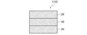
- FIG. 2 is a cross-sectional view illustrating an example of a metal member according to an embodiment.
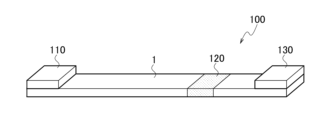
- FIG. 3 is a perspective view showing an example of a test strip using an analytical carrier according to one embodiment.
- FIG. 4 is a scanning image of the test strips for measuring autofluorescence according to Example 3 and Reference Example 1 at an excitation wavelength of 488 nm.
- FIG. 5 is a scanning image of the test strips for measuring autofluorescence according to Example 3 and Reference Example 1 at an excitation wavelength of 532 nm.
- FIG. 6 is a scanning image of the test strips on which the antibodies according to Example 3 and Reference Example 1 are immobilized at an excitation wavelength of 488 nm.
- FIG. 7 is a scanning image of the test strips on which the antibodies according to Example 3 and Reference Example 1 are immobilized at an excitation wavelength of 532 nm.
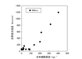
- FIG. 8 is a graph showing the relationship between the total organic acid concentration and the autofluorescence intensity.
- FIG. 9 is a graph showing the relationship between the total inorganic acid concentration and the autofluorescence intensity.
- the analytical carrier according to this embodiment will be described.
- a nitrocellulose membrane filter when used as an analytical carrier, it generates high autofluorescence, which is an obstacle to achieving high sensitivity. Therefore, in the analytical carrier according to this embodiment, the organic acid concentration of the metal member is reduced.
- the analytical carrier according to this embodiment can suppress the autofluorescence of the analytical carrier by reducing the organic acid concentration. Note that autofluorescence is also called autofluorescence or primary fluorescence, and refers to fluorescence generated by the inherent characteristics of the analytical carrier.
- ⁇ Porous body> 1 is a schematic cross-sectional view showing a partially enlarged structure of a porous body 20 of an analytical carrier 1.
- the analytical carrier 1 includes a metal member 10, and the metal member 10 includes a porous body 20.
- the porous body 20 includes a plurality of aluminum particles 21.
- the porous body 20 includes a plurality of voids 23.
- the porous body 20 includes a skeleton 22 formed by an assembly of a plurality of aluminum particles 21, and the voids 23 surrounded by the skeleton 22.
- the skeleton 22 includes an outer shell 24, and the surface of the skeleton 22 is formed by the outer shell 24.
- the plurality of aluminum particles 21 are connected via the outer shell 24 to form a skeleton 22 with a three-dimensional mesh structure, and the outer shell 24 is disposed on the outer surface side of the analytical carrier 1.
- the porous body 20 is a porous body having voids 23 inside that communicate with the outside.
- the voids 23 are surrounded by the outer shell 24. That is, the voids 23 are formed surrounded by the skeleton 22 inside the porous body 20 or the outer shell 24 formed on its surface.
- the voids 23 forming one cell structure surrounded by the outer shell 24 may be connected to the voids 23 forming another cell structure.
- the porous body 20 may have an open cell structure.
- the single void 23 or multiple voids 23 may or may not penetrate from one surface of the porous body 20 to the other surface.
- the analytical carrier 1 includes a porous body 20.
- the porous body 20 is made by sintering aluminum powder containing a plurality of aluminum particles 21, or a compact obtained by compacting the aluminum powder, to obtain a sintered body, and then subjecting the sintered body to an anodizing process described below.
- the porous body 20 includes a skeleton 22 formed by an assembly of the plurality of aluminum particles 21.
- the porous body 20 also includes voids 23 surrounded by the skeleton 22.
- the skeleton 22 has an outer shell 24 on the surface of the aluminum particles 21.
- labels such as fluorescent beads are used.
- the porous body 20 can suck up the solution in which the label is dispersed by capillary action. The mechanism by which this happens is believed to be that the solution in which the label is dispersed penetrates into the spaces of the voids 23 present inside the porous body 20, and that a portion of the solution travels along the surface of the porous body 20.
- the average particle diameter of the multiple aluminum particles 21 is 0.1 ⁇ m to 20 ⁇ m. By making the average particle diameter 0.1 ⁇ m or more, the strength of the porous body 20 is improved and damage during transportation, etc. can be suppressed. By making the average particle diameter 20 ⁇ m or less, the flow rate of the analytical carrier 1 can be improved.
- the average particle diameter may be 1 ⁇ m or more, 3 ⁇ m or more, or 5 ⁇ m or more.
- the average particle diameter may be 18 ⁇ m or less, 15 ⁇ m or less, or 10 ⁇ m or less.
- the average particle diameter of the plurality of aluminum particles 21 can be measured by observing the cross section of the porous body 20 with a scanning electron microscope. For example, the aluminum particles 21 after sintering are partially melted and connected, but the portion having an approximately circular shape can be considered to be approximately circular. In the above cross-sectional observation, the maximum diameter (long diameter) of each of the aluminum particles 21 having an approximately circular shape is taken as the particle diameter, and the particle diameters of 50 arbitrary aluminum particles 21 are measured, and the arithmetic average of these is taken as the average particle diameter of the aluminum particles 21 after sintering.
- the average particle diameter of the plurality of aluminum metal particles before sintering is the D50 value obtained by measuring the particle size distribution on a volume basis by a laser diffraction method.
- the average particle diameter of the aluminum particles 21 after sintering observed with a scanning electron microscope is almost the same as the average particle diameter of the aluminum metal particles before sintering measured by a laser diffraction method.
- each aluminum particle 21 is not particularly limited, and may be spherical, polygonal, irregular, scaly, or fibrous. Among these, it is preferable that each aluminum particle 21 contained in the plurality of aluminum particles has a spherical shape.
- the size of the plurality of voids 23 becomes uniform. For example, in immunochromatography, as described later, labels such as fluorescent beads are used. If the size of the voids 23 is uniform, such labels are not captured in the voids 23 and can flow smoothly through the porous body 20.
- the spherical shape referred to here is not only a perfect sphere, but may also have a slight unevenness on the surface.
- the spherical shape referred to here may include not only those with an aspect ratio of 1, but also those with an aspect ratio of 5 or less, 3 or less, or 2 or less.
- the aspect ratio is the ratio of the major axis to the minor axis of the aluminum particle 21, and is the average value of the plurality of aluminum particles 21.
- the average pore diameter of the porous body 20 is preferably 2.5 ⁇ m to 20 ⁇ m. By making the average pore diameter 2.5 ⁇ m or more, the water suction performance of the analytical carrier 1 can be improved.
- the particle diameter of typical fluorescent beads used in immunochromatography is about 10 nm to 50 nm, and there are also labels with larger particle diameters.
- the analytical carrier 1 is used, for example, in an immunochromatographic test strip, by making the average pore diameter 2.5 ⁇ m or more, such labels are not captured in the voids 23 and can flow smoothly through the porous body 20.
- the average pore diameter 20 ⁇ m or less the water suction performance of the analytical carrier 1 can be improved.
- the average pore diameter may be 3 ⁇ m or more, or may be 4 ⁇ m or more.
- the average pore diameter may be 15 ⁇ m or less, or may be 10 ⁇ m or less.
- the average pore diameter can be measured by mercury intrusion porosimetry. In this specification, the average pore size refers to the median size based on volume.
- the porosity of the porous body 20 is 30% by volume or more.
- the porosity of the porous body 20 may be 30% to 99% by volume.
- the water suction performance can be improved.
- the porosity 99% by volume or less peeling of the aluminum particles 21 from the porous body 20 can be suppressed, and the strength of the porous body 20 can be improved.
- the porosity may be 40% by volume or more, 50% by volume or more, 60% by volume or more, 70% by volume or more, 80% by volume or more, 90% by volume or more, or 92% by volume or more.
- the porosity may be 95% by volume or less, or 93% by volume or less.
- the porosity is the ratio of the volume of the pores in the porous body 20 to the total volume of the porous body 20.
- the porosity can be obtained by dividing the pore volume occupied by the voids 23 contained in the porous body 20 by the apparent volume of the porous body 20, which is obtained by submerging the analytical carrier in water and evacuating it, as described in the Examples section below.
- the outer shell 24 includes an anodized film containing aluminum oxide.
- the anodized film included in the outer shell 24 may be a barrier-type anodized film or a porous-type anodized film.
- the outer shell 24 may have only a barrier-type anodized film formed on the surface of the aluminum particle 21, or may have a two-layer structure in which a barrier-type anodized film is formed on the surface of the aluminum particle 21 and a porous-type anodized film is further formed on the outside.
- the outer shell 24 may have a hydrated film containing aluminum hydroxide. The hydrated film is formed in a hydration treatment process described later.
- the outer shell 24 preferably has a thickness of 0.1 nm to 1000 nm. By setting the thickness of the outer shell 24 within this range, an analytical carrier 1 with sufficiently high corrosion resistance can be provided.
- the thickness of the outer shell 24 may be 1 nm or more, or 10 nm or more.
- the thickness of the outer shell 24 may be 200 nm or less, or 100 nm or less.
- the thickness of the outer shell 24 can be measured, for example, by observing a cross section of the outer shell 24 with a scanning electron microscope or the like.
- the metal member 10 may further include a substrate 50. That is, the metal member 10 may include only the porous body 20 and, optionally, the substrate 50. Alternatively, the metal member 10 may include only the porous body 20 and the substrate 50. Alternatively, the metal member 10 may include only the porous body 20.
- the substrate 50 can support the porous body 20 and can improve the rigidity of the analytical support 1.
- the substrate 50 may have a layered or plate-like shape.
- the porous body 20 may be provided on at least one side of the substrate 50. Specifically, the porous body 20 may be provided on only one side of the substrate 50, or on both sides of the substrate 50. The porous body 20 is preferably disposed on the outermost surface of the analytical carrier 1.
- the analytical carrier 1 does not necessarily have to include a substrate 50, so the thickness of the substrate 50 is greater than 0 ⁇ m.
- the thickness of the substrate 50 depends on the application, but may be, for example, 1 mm or less, 100 ⁇ m or less, 10 ⁇ m or less, or 1 ⁇ m or less.
- the thickness of the metal member 10 may vary depending on the application, but may be, for example, 20 ⁇ m or more and 10 cm or less. By setting the thickness of the metal member 10 within this range, an analytical carrier 1 with good bending strength can be provided.
- the thickness of the metal member 10 may be 30 ⁇ m or more, 50 ⁇ m or more, 100 ⁇ m or more, or 150 ⁇ m or more.
- the thickness of the metal member 10 may be 1000 ⁇ m or less, 300 ⁇ m or less, or 200 ⁇ m or less.
- the organic acid concentration of the metal member 10 is 150 mg/m 2 /100 ⁇ m or less.
- the organic acid concentration of the metal member 10 is 150 mg/m 2 /100 ⁇ m or less.
- the generation of autofluorescence from the porous body 20 can be suppressed.
- the organic acid concentration of the metal member 10 when the analytical carrier 1 is subjected to a fluorescence measurement after a flow test in which a solution containing an analyte is passed through the analytical carrier 1, the background signal intensity and noise value emitted from areas other than the spot where the analyte is detected can be reduced. In this way, according to the analytical carrier 1, when an analysis is performed in which excitation light is irradiated onto the analytical carrier 1 and the emitted light is detected, the signal from the spot derived from the analyte can be easily detected with high sensitivity.
- the analytical carrier 1 is not limited to the following mechanism, it is presumed that the autofluorescence was suppressed by reducing the organic acid concentration because the anodized film of the porous body 20 contained fewer conjugated systems. In general, the presence of conjugated systems such as double bonds and benzene rings causes fluorescence from the conjugated systems. As described below, the anodized film is produced by anodizing in an electrolyte, and the components contained in the electrolyte during anodization are incorporated into the anodized film.
- the organic acid itself does not emit fluorescence, it is considered that when the electrolyte contains an organic acid, the organic acid contained in the electrolyte is oxidized to generate organic acid-derived substances containing conjugated systems.
- organic acid-derived substances are generated from the organic acid incorporated into the anodized film, or that organic acid-derived substances generated in the electrolyte are incorporated into the anodized film, causing the porous body 20 to contain organic acid-derived substances.
- the autofluorescence increases due to an increase in the fluorescence generated from the conjugated system of the organic acid-derived substance contained in the porous body 20.
- anodization is performed in an electrolyte containing an organic acid and the anodized film becomes thick, it is believed that the autofluorescence increases due to the incorporation of a large amount of organic acid or organic acid-derived substance into the anodized film.
- the organic acid concentration is the total content of organic acids in an extract obtained by extracting the metal member 10 of the analytical carrier 1 with a liquid containing water, as described in the Examples section below.
- the organic acid concentration means the content of organic acids contained per m2 of projected area in a metal member 10 having a thickness of 100 ⁇ m.
- the organic acid concentration can be calculated by ion analysis using the extract. The ion analysis can be performed by ion chromatography and ICP emission spectrometry, as described in the Examples section below.
- the anodized film may be an organic acid anodized film or an inorganic acid anodized film.
- the organic acid anodized film suppresses the denaturation of proteins such as antibodies bound to the analytical carrier 1, and therefore can suppress the decrease in signal intensity from labels such as fluorescent substances. This can improve the signal-to-noise ratio.
- the organic acid anodized film refers to an anodized film in which the concentration of organic acid eluted from the anodized film is higher than the inorganic acid concentration.
- the organic acid anodized film may have an organic acid concentration of 60% or more, 70% or more, 80% or more, or 90% or more of the total of the organic acid concentration and the inorganic acid concentration.
- the inorganic acid anodized film refers to an anodized film in which the concentration of inorganic acid eluted from the anodized film is higher than the organic acid concentration.
- the inorganic acid anodized film may have an inorganic acid concentration of 60% or more, 70% or more, 80% or more, or 90% or more of the total of the organic acid concentration and the inorganic acid concentration.
- the organic acid anodized film may be formed by anodizing with an electrolyte containing an organic acid.
- the inorganic acid anodized film may be formed by anodizing with an electrolyte containing an inorganic acid.
- the organic acid concentration may be measured by the method described above, and the inorganic acid concentration may be measured by the same method. Anodization will be described later.
- the anodized film may be at least one selected from the group consisting of a citric acid anodized film, an adipic acid anodized film, and an oxalic acid anodized film.
- Such organic acid anodized films are less likely to cause denaturation of proteins such as antibodies bound to the analytical carrier 1, and therefore can suppress a decrease in signal intensity from labels such as fluorescent substances. This can improve the S/N ratio.
- the citric acid anodized film refers to an anodized film in which the organic acid with the highest concentration of the organic acid eluted from the anodized film is citric acid.
- the adipic acid anodized film refers to an anodized film in which the organic acid with the highest concentration of the organic acid eluted from the anodized film is adipic acid.
- the oxalic acid anodized film refers to an anodized film in which the organic acid with the highest concentration of the organic acid eluted from the anodized film is oxalic acid. The concentrations of these organic acids can be measured by ion analysis in the same manner as described above.
- the anodized film may be at least one selected from the group consisting of a sulfuric acid anodized film, a phosphoric acid anodized film, and a boric acid anodized film.
- Such inorganic acid anodized films have a low organic acid concentration in the metal member 10. Therefore, the generation of autofluorescence from the analytical carrier 1 is suppressed, and the background signal strength and noise value after the flow test can be reduced.
- the sulfuric acid anodized film refers to an anodized film in which the inorganic acid eluted from the anodized film has the highest concentration of sulfuric acid.
- the phosphoric acid anodized film refers to an anodized film in which the inorganic acid eluted from the anodized film has the highest concentration of phosphoric acid.
- the boric acid anodized film refers to an anodized film in which the inorganic acid eluted from the anodized film has the highest concentration of boric acid.
- the anodized film may be at least one selected from the group consisting of citric acid anodized film, adipic acid anodized film, oxalic acid anodized film, phosphoric acid anodized film, and boric acid anodized film.
- Such anodized films are less likely to cause denaturation of proteins such as antibodies bound to the analytical carrier 1, and therefore can suppress a decrease in signal intensity from labels such as fluorescent substances. This can improve the signal-to-noise ratio.
- the anodized film may be a weak acid anodized film. Such an anodized film is less likely to cause denaturation of proteins such as antibodies bound to the analytical carrier 1, and therefore can suppress a decrease in signal intensity from labels such as fluorescent substances. This can improve the signal-to-noise ratio.
- the weak acid anodized film refers to an anodized film in which the acid eluted from the anodized film with the highest concentration is a weak acid.
- the weak acid anodized film may be at least one selected from the group consisting of citric acid anodized film, adipic acid anodized film, oxalic acid anodized film, phosphoric acid anodized film, and boric acid anodized film.
- the analytical support 1 is an analytical support 1 including a metal member 10 including a porous body 20.
- the porous body 20 includes a skeleton 22 formed by an assembly of a plurality of aluminum particles 21, and a plurality of voids 23 surrounded by the skeleton 22.
- the skeleton 22 has an outer shell 24 including an anodized film containing aluminum oxide on the surface of the aluminum particle 21.
- the porosity of the porous body 20 is 30 volume % or more.
- the average particle diameter of the plurality of aluminum particles 21 is 0.1 ⁇ m to 20 ⁇ m.
- the organic acid concentration of the metal member 10 is 150 mg/m 2 /100 ⁇ m or less.
- the low organic acid concentration in the metal member 10 suppresses the autofluorescence emitted from the porous body 20.
- the low organic acid concentration in the metal member 10 reduces the background signal strength and noise value after the flow test. Therefore, according to the analytical carrier 1, it is possible to provide an analytical carrier 1 capable of detecting signals from spots derived from the analyte with high sensitivity.
- the analytical carrier 1 may be an analytical carrier 1 for performing fluorescence analysis in which the fluorescence emitted by irradiating the analytical carrier 1 with excitation light is measured.
- the analytical carrier 1 according to this embodiment is capable of suppressing autofluorescence, and therefore can be suitably used as a carrier for fluorescence analysis.
- the wavelength of the irradiated excitation light may be 250 nm to 650 nm, and the wavelength of the measured fluorescence may be 350 nm to 700 nm.
- excitation wavelengths and fluorescence wavelengths are widely used in general fluorescence analysis, so the analytical carrier 1 according to this embodiment can be widely used.
- the analytical carrier 1 is capable of carrying and analyzing the analyte.
- the analytical carrier 1 suppresses autofluorescence and also suppresses background signal strength and noise, and is therefore suitable for use as an immunochromatographic test strip.
- an immunochromatographic test strip is also called an immunochromatographic developing member, a lateral flow assay test strip, or a lateral flow assay developing member.
- the analytical carrier 1 is also preferably used in in vitro diagnostic pharmaceuticals such as test kits that utilize immunochromatography.
- the analytical carrier 1 can suck up liquid by capillary action due to the porous body 20, and therefore can be used in lateral flow assays.
- the flow rate which indicates the speed at which the analytical carrier 1 sucks up liquid in the longitudinal direction, is not particularly limited, but may be, for example, 1500 seconds or less. In this way, an analytical carrier 1 suitable for, for example, chromatography can be provided.
- the flow rate may be 1000 seconds or less, 500 seconds or less, 300 seconds or less, 200 seconds or less, or 100 seconds or less.
- the flow rate can be obtained by immersing the analytical carrier 1 in pure water at room temperature (30°C) so that the planar direction of the analytical carrier 1 is perpendicular to the liquid surface, and measuring the time required to suck up water to a height of 4 cm by capillary action.
- the pure water has a resistivity of 10 k ⁇ m measured at 30°C.
- the method for manufacturing the analytical carrier 1 according to this embodiment includes a sintering step and an anodizing step.
- the method for manufacturing the analytical carrier 1 may also include a hydration step, if necessary.
- the sintering step produces a sintered material containing a sintered body in which a plurality of aluminum metal particles are sintered.
- the sintered material may further include a base material.
- the sintered body is subjected to a hydration step and an anodizing step, if necessary. That is, the sintered material containing the sintered body is subjected to a hydration step and an anodizing step, if necessary, to produce a metal member 10 containing a porous body 20.
- Each step will be described in detail below.
- ⁇ Sintering process> a plurality of aluminum metal particles are sintered to obtain a sintered body, each of which contains at least one of pure aluminum and an aluminum alloy.
- the purity of the pure aluminum may be 99.00% by mass or more, 99.50% by mass or more, 99.80% by mass or more, 99.99% by mass or more, or 99.995% by mass or more.
- Pure aluminum may contain elements other than aluminum (Al).
- the elements other than aluminum contained in pure aluminum may include one or more of silicon (Si), iron (Fe), copper (Cu), manganese (Mn), magnesium (Mg), chromium (Cr), zinc (Zn), titanium (Ti), vanadium (V), gallium (Ga), nickel (Ni), boron (B), zirconium (Zr), etc.
- the content of each of the elements other than aluminum contained in pure aluminum may be less than 1% by mass, or less than 0.01% by mass.
- Aluminum alloys contain aluminum and elements other than aluminum.
- the elements other than aluminum contained in the aluminum alloy may include one or more of the following elements: silicon (Si), iron (Fe), copper (Cu), manganese (Mn), magnesium (Mg), chromium (Cr), zinc (Zn), titanium (Ti), vanadium (V), gallium (Ga), nickel (Ni), boron (B), zirconium (Zr), etc.
- the total content of the elements other than aluminum contained in the aluminum alloy may be more than 1 mass%.
- the total content of the elements other than aluminum contained in the aluminum alloy may be 10 mass% or less, or 5 mass% or less.
- the total content of the elements other than aluminum contained in the aluminum alloy may be 10 mass% or less, or 1 mass% or less.
- at least one of pure aluminum and aluminum alloy is also simply referred to as aluminum.
- the average particle diameter of the aluminum metal particles is 0.1 to 20 ⁇ m.
- the average particle diameter of the aluminum metal particles before sintering is the D50 value obtained by measuring the particle size distribution on a volume basis using a laser diffraction method.
- the shape of the particles is not particularly limited, and may be spherical, polygonal, irregular, scaly, fibrous, or the like.
- the aluminum metal particles can be manufactured by known methods.
- the aluminum metal particles can be manufactured by, for example, an atomization method, a melt spinning method, a rotating disk method, a rotating electrode method, or other rapid solidification methods.
- the aluminum metal particles are preferably manufactured by an atomization method, and more preferably manufactured by a gas atomization method.
- the aluminum metal particles are preferably manufactured by atomizing a molten metal.
- the aluminum metal particles may be disposed on at least one surface of the substrate, and then sintered. On at least one surface of the substrate, aluminum powder containing a plurality of aluminum metal particles may be disposed, a green compact obtained by compacting the aluminum powder may be disposed, or a liquid composition such as a slurry containing a plurality of aluminum metal particles may be disposed.
- the liquid composition may be applied to the surface of the substrate by a known method such as spray coating, brush coating, roller coating, air knife coating, bar coating, spin coating, dipping, or screen printing. The liquid composition may be applied so as to obtain the desired thickness of the porous body 20, taking into consideration the composition.
- the surface of the substrate may be pretreated before the plurality of aluminum metal particles are disposed on the surface of the substrate.
- the pretreatment may include a step of roughening the surface of the substrate.
- the pretreatment is not particularly limited and may be cleaning, etching, blasting, or the like.
- the substrate may contain resin or metal.
- the resin is burned by sintering, and the substrate can be removed from the analytical carrier 1 after sintering.
- the substrate contains metal, the substrate 50 can be left on the analytical carrier 1.
- the thickness of the substrate is greater than 0 ⁇ m.
- the thickness of the substrate depends on the application, and may be, for example, 1 mm or less, 100 ⁇ m or less, 10 ⁇ m or less, or 1 ⁇ m or less.
- the metal substrate may be made of the same material as the substrate 50 described above.
- the content of aluminum metal particles in the composition is preferably 20% by mass or more, more preferably 30% by mass or more, and even more preferably 31% by mass or more.
- the content of aluminum metal particles in the composition is preferably 70% by mass or less, more preferably 60% by mass or less, and even more preferably 57% by mass or less.
- the pore-forming material is a material that promotes the formation of voids in the sintered body.
- the pore-forming material may be, for example, particles containing a polymeric material. It is preferable that the pore-forming material has low solubility in the solvent described below.
- the polymeric material may contain a polysaccharide or a resin.
- the polysaccharide may contain, for example, starch.
- the resin may contain a polyolefin such as polyethylene or polypropylene.
- the average particle diameter of the pore-forming material is preferably 0.1 ⁇ m or more and 20 ⁇ m or less. By making the average particle diameter of the pore-forming material 0.1 ⁇ m or more, the average pore diameter can be easily made 2.5 ⁇ m or more. By making the average particle diameter of the pore-forming material 20 ⁇ m or less, the average pore diameter can be easily made 20 ⁇ m or less.
- the average particle diameter of the pore-forming material is more preferably 0.5 ⁇ m or more, and even more preferably 1 ⁇ m or more. In addition, the average particle diameter of the pore-forming material is preferably 10 ⁇ m or less, and more preferably 8 ⁇ m or less.
- the average particle diameter of the pore-forming material is the D50 value obtained by measuring the particle size distribution on a volume basis by laser diffraction method.
- the content of the pore-forming material in the composition is preferably 5% by mass or more, more preferably 10% by mass or more, and even more preferably 12% by mass or more.
- the content of the pore-forming material in the composition is preferably 30% by mass or less, more preferably 25% by mass or less, and even more preferably 23% by mass or less.
- the binder preferably has high solubility in the solvent described below.
- the binder may contain, for example, synthetic resins such as carboxy-modified polyolefin resin, vinyl acetate resin, vinyl chloride resin, vinyl chloride-vinyl acetate copolymer resin, vinyl alcohol resin, butyral resin, vinyl fluoride resin, acrylic resin, polyester resin, urethane resin, epoxy resin, urea resin, phenol resin, acrylonitrile resin, nitrocellulose resin, paraffin wax, or polyethylene wax, or natural resins such as wax, tar, glue, urushi, rosin, or beeswax.
- the content of the binder in the composition is preferably 0.5% by mass or more, and more preferably 1% by mass or more.
- the content of the binder in the composition is preferably 30% by mass or less, and more preferably 20% by mass or less.
- the solvent may contain an organic solvent such as water, ethanol, toluene, ketones, or esters. If necessary, the laminate with the composition applied to the substrate may be dried at a temperature of 20°C or higher and 300°C or lower for 1 to 30 minutes to volatilize the solvent.
- the sintering temperature is not particularly limited, but is preferably 560°C or higher and 660°C or lower. By setting the sintering temperature to 560°C or higher, the strength of the porous body 20 can be improved. By setting the sintering temperature to 660°C or lower, melting of multiple aluminum metal particles can be suppressed.
- the sintering temperature is more preferably 570°C or higher, and even more preferably 580°C or higher. Furthermore, the sintering temperature is more preferably 650°C or lower, and even more preferably 620°C or lower.
- the sintering time depends on the sintering temperature, etc., but may be, for example, about 5 to 24 hours.
- the sintering atmosphere is not particularly limited, and may be, for example, a vacuum atmosphere, an inert gas atmosphere, an oxidizing gas atmosphere (air), or a reducing gas atmosphere. Of these, the sintering atmosphere is preferably a vacuum atmosphere or a reducing gas atmosphere.
- the sintering conditions may be any pressure condition of normal pressure, reduced pressure, or increased pressure.
- the composition contains a pore-forming material
- the pore-forming material can be burned slowly, and more uniformly distributed voids can be formed in the sintered body.
- the heating temperature is preferably 250°C or higher, and more preferably 280°C or higher.
- the heating temperature is preferably 460°C or lower, and more preferably 430°C or lower.
- the heating time is preferably 5 hours or more and 20 hours or less. By setting the heating time to 5 hours or more, more uniformly distributed voids can be formed in the sintered body. By setting the heating time to 20 hours or less, sintering between the aluminum metal particles is prevented from progressing, and more uniformly distributed voids can be formed in the sintered body.
- the heating time is more preferably 7 hours or more, and more preferably 15 hours or less.
- the sintering atmosphere may be any of a vacuum atmosphere, an inert gas atmosphere, and an oxidizing gas atmosphere.
- the sintering conditions may be any of normal pressure, reduced pressure, and increased pressure conditions.
- the sintering process may include a first sintered layer forming process for obtaining a first sintered layer, and a second sintered layer forming process for obtaining a second sintered layer.
- a first sintered layer forming process a plurality of aluminum metal particles may be sintered to obtain the first sintered layer.
- the plurality of aluminum metal particles may be arranged on at least one surface of the substrate, and then sintered.
- a laminate in which a plurality of aluminum metal particles are arranged on the surface of the first sintered layer may be sintered.
- At least one of the average particle size, aspect ratio, or constituent material of the plurality of aluminum metal particles used, the composition of the composition, or the type or average particle size of the pore-forming material may be different.
- the filling rate of the sintered body is 20% to 70% by volume.
- the filling rate of the sintered body is 20% to 70% by volume.
- the filling rate may be 30% by volume or more, 40% by volume or more, or 50% by volume or more. Furthermore, the filling rate may be 65% by volume or less, 60% by volume or less, or 55% by volume or less. As described in the Examples section below, the filling rate can be obtained by subtracting the mass of the base material from the mass of the entire sintered material to obtain the mass of the sintered body portion, and then dividing the result by the mass of the sintered body portion when the filling rate is assumed to be 100%.
- the manufacturing method of the analytical carrier 1 according to the present embodiment may include a hydration step before the anodization step.
- the hydration step is a step for efficiently forming an anodized film by forming a hydration film on the surface of the aluminum metal particles, and converting the hydration film into an oxide film during the subsequent anodization step.
- there is an effect of lifting and cleaning dirt present on the aluminum surface before anodization from the aluminum surface, and when an anodized film is subsequently applied the occurrence of unevenness in the appearance can be suppressed.
- the occurrence of fluorescence derived from organic matter attached to the aluminum surface can be suppressed.
- the hydration step is a step for heat-treating the sintered body with warm water such as boiling water.
- the warm water may be pure water, or may be an aqueous phosphoric acid solution in which phosphoric acid is dissolved.
- the concentration of the aqueous phosphoric acid solution may be, for example, 0.001 mL/L to 5 mL/L.
- the aqueous phosphoric acid solution of this concentration can be obtained, for example, by preparing an 85% by mass aqueous phosphoric acid solution with pure water to a desired concentration.
- the addition of phosphoric acid enhances the cleaning effect of the surface.
- the outer shell 24 When the sintered body is subjected to a hydration treatment, a hydration film of aluminum hydroxide is formed on the surface of the aluminum, and as described above, the outer shell 24 may include a hydration film, but the outer shell 24 may also include a hydration film.
- the sintered body is anodized to form an outer shell 24 including an anodized film on the surface of the aluminum metal particle.
- an anode on which the sintered body is placed and a cathode on which stainless steel (SUS) is placed are immersed in an electrolytic solution to perform electrolysis.
- the sintered body may be anodized using an electrolyte containing an organic acid.
- anodizing the sintered body using an electrolyte containing an organic acid the above-mentioned organic acid anodized film can be formed.
- the sintered body may be anodized using an electrolyte containing at least one selected from the group consisting of citric acid, adipic acid, and oxalic acid, and salts thereof. Examples of these salts include ammonium salts, sodium salts, potassium salts, and silicates.
- the above-mentioned citric acid anodized film can be formed.
- the above-mentioned adipic acid anodized film can be formed.
- the above-mentioned oxalic acid anodized film can be formed.
- the sintered body may be anodized using an electrolyte containing an inorganic acid.
- anodizing the sintered body using an electrolyte containing an inorganic acid the above-mentioned inorganic acid anodized film can be formed.
- the sintered body may be anodized using an electrolyte containing at least one selected from the group consisting of sulfuric acid, phosphoric acid, and boric acid, and salts thereof. Examples of these salts include ammonium salts, sodium salts, potassium salts, and silicates.
- the above-mentioned sulfuric acid anodized film can be formed.
- the above-mentioned phosphoric acid anodized film can be formed.
- the above-mentioned boric acid anodized film can be formed.
- an electrolyte containing a weak acid may be used for anodization.
- a strong acid such as sulfuric acid
- the strong acid may cause the protein to denature due to the loss of binding bonds (functional groups) of the protein adsorbed to the porous body 20 or a change in three-dimensional structure.
- the signal intensity from a label such as a fluorescent substance may decrease, and the S/N ratio may decrease. Therefore, the S/N ratio can be improved by using an electrolyte containing a weak acid.
- a weak acid has an acid dissociation constant pKa of more than 1.2, preferably more than 1.8, and more preferably more than 3.0, measured at 25°C.
- an electrolyte containing at least one acid selected from the group consisting of citric acid, adipic acid, oxalic acid, phosphoric acid, and boric acid may be used for the anodization. Electrolytes containing such weak acids are less likely to denature proteins, and therefore can suppress a decrease in signal intensity from labels such as fluorescent substances. This can improve the signal-to-noise ratio.
- the electrolysis temperature may be 0°C or higher, 10°C or higher, 20°C or higher, 30°C or higher, 40°C or higher, or 50°C or higher.
- the electrolysis temperature may be 70°C or lower, 60°C or lower, or 50°C or lower.
- the electrolysis voltage may be 0.1V or higher or 1V or higher, depending on the type of electrolyte.
- the electrolysis voltage may be 500V or lower or 400V or lower, depending on the type of electrolyte.
- the electrolysis time may be 0.1 minutes or more or 1 minute or more.
- the electrolysis time may be 60 minutes or less or 20 minutes or less.
- the anodization may be performed in a single step, or may be performed in a number of different steps.
- the method for producing an analytical carrier 1 is a method for producing an analytical carrier 1 including a metal member 10 including a porous body 20.
- the porous body 20 includes a skeleton 22 formed by an assembly of a plurality of aluminum particles 21, and a plurality of voids 23 surrounded by the skeleton 22.
- the skeleton 22 has an outer shell 24 including an anodized film including aluminum oxide on the surface of the aluminum particle 21.
- the production method includes a sintering step of sintering a plurality of aluminum metal particles to obtain a sintered body, and an anodizing step of anodizing the sintered body to form an outer shell 24 including an anodized film on the surface of the aluminum metal particle.
- the average particle diameter of the plurality of aluminum metal particles is 0.1 ⁇ m to 20 ⁇ m.
- the packing rate of the sintered body is 20 vol % to 70 vol %.
- the organic acid concentration of the metal member 10 is 150 mg/m 2 /100 ⁇ m or less.
- the analytical method according to this embodiment is an analytical method for analyzing an analyte supported on an analytical carrier 1.
- the analyte include amino acids, peptides, proteins, genes, sugars, lipids, cells, and complexes thereof. More specifically, examples of the analyte include peptides such as PCT (procalcitonin); proteins such as urinary albumin; hormones such as HCG (human chorionic gonadotropin) and LH (luteinizing hormone); HBs antigen, rotavirus antigen, adenovirus antigen, RSV (Respiratory Syndrome), and the like.
- Viral infections such as HBs antibody, HCV antibody, EBV antibody, RSV antibody, rubella virus antibody, measles virus antibody, enterovirus antibody, dengue virus antibody, and SARS antibody.
- antigens or antibodies of bacterial infections such as pneumococcus antigens, mycoplasma antigens, group A hemolytic streptococcus antigens, legionella antigens, mycobacterium tuberculosis antigens, gonorrhea antigens, tetanus antigens, mycoplasma antibodies, Helicobacter pylori antibodies, and mycobacterium tuberculosis antibodies; antigens or antibodies of chlamydia infections such as chlamydia antigens; antigens or antibodies of spirochete infections such as Treponema pallidum antibodies; antigens or antibodies of protozoal diseases such as malaria antibodies and toxoplasma antibodies.
- the analysis method includes an irradiation step of irradiating light and a detection step of detecting the light.
- the analytical carrier 1 carrying the analyte is irradiated with light having at least one wavelength included in the ultraviolet to infrared regions.
- the irradiated light is also called incident light incident on the analytical carrier 1.
- the irradiated light may include a light beam or may be a light beam.
- the irradiated light may have a continuous wavelength, a discontinuous wavelength, or a single wavelength.
- the irradiated light may have a wavelength included in at least one region selected from the group consisting of the ultraviolet region, the visible region, and the infrared region.
- the wavelength in the ultraviolet region may be 10 nm or more and less than 380 nm
- the wavelength in the visible region may be 380 nm or more and less than 780 nm
- the wavelength in the infrared region may be 780 nm or more and less than 1 mm.
- the irradiated light may have any wavelength within the range of 10 nm or more and less than 1 mm.
- the excitation light may have a continuous wavelength, a discontinuous wavelength, or a single wavelength.
- the light in the ultraviolet region may include at least one of near ultraviolet light and vacuum ultraviolet light.
- Near ultraviolet light may include light having a wavelength of 200 nm or more and less than 380 nm.
- Vacuum ultraviolet light may include light having a wavelength of 10 nm or more and less than 200 nm.
- Near ultraviolet light may include at least one type selected from the group consisting of UVA, UVB, and UVC.
- UVA may include light having a wavelength of 315 nm or more and less than 380 nm.
- UVB may include light having a wavelength of 280 nm or more and less than 315 nm.
- UVC may include light having a wavelength of 200 nm or more and less than 280 nm.
- the light in the infrared region may include at least one type selected from the group consisting of near-infrared light, mid-infrared light, and far-infrared light.
- the near-infrared light may include light having a wavelength of 780 nm or more and less than 2.5 ⁇ m.
- the mid-infrared light may include light having a wavelength of 2.5 ⁇ m or more and less than 4 ⁇ m.
- the far-infrared light may include light having a wavelength of 4 ⁇ m or more and less than 1 mm.
- the light can be emitted by a light source.
- the light source can include, for example, an LED, a laser diode, an incandescent lamp, a halogen lamp, a tungsten lamp, a xenon lamp, a halogen lamp, a metal halide lamp, or a high pressure mercury lamp.
- the detection step of detecting light is a step of detecting at least one type of outgoing light selected from the group consisting of reflected light, scattered light, transmitted light, fluorescence, and phosphorescence of irradiated light.
- the detector may obtain one-dimensional information (point information), two-dimensional information (line information), or three-dimensional information (stereoscopic space information) on the analytical carrier 1 in a state in which the analyte is supported.
- the detector may detect the wavelength to be detected, and may detect light by cutting unnecessary light through a filter or the like.
- the detection of the outgoing light may be performed visually by observing the outgoing light emitted from the analytical carrier 1 with the naked eye.
- the detector may have a light receiving element such as a photomultiplier tube (PMT), a photodiode (PD), a complementary metal oxide semiconductor (CMOS) sensor, or a charge-coupled device (CCD) sensor.
- the detector may output the detection result of the detected light to an output unit.
- the output unit may be, for example, an LCD, a CRT, or a printer.
- test kit includes a test strip 100 having the analytical carrier 1.
- the test strip 100 includes the analytical carrier 1, a specimen supplying section 110, and an absorbing section 130.
- the analytical carrier 1 is provided with a determination section 120.
- the test kit further includes a case (not shown in the drawing) for storing the test strip 100.
- the specimen supply section 110 may contain, for example, a labeled antibody that specifically binds to an antigen that is the subject of analysis. Examples of subjects of analysis by the test kit include those similar to those described above.
- a specimen collected from a living organism or the like is supplied to the specimen supply section 110 and mixed with the labeled antibody to form a mixed liquid.
- the mixed liquid is developed to the determination section 120 by capillary action of the analytical carrier 1, and excess specimen is absorbed by the absorption section 130.
- the determination unit 120 has, for example, a test line and a control line.
- a capture antibody that specifically binds to the analyte is fixed to the test line.
- a labeled antibody is fixed to the capture antibody on the test line via the analyte.
- an antibody that specifically binds to the labeled antibody is fixed to the control line.
- the labeled antibody binds to the antibody fixed to the control line.
- the labeled antibody contains a label that includes particles such as fluorescent beads, and an antibody that binds to the label to form a complex and specifically binds to the analyte. Therefore, if there is a location where the concentration or density of the labeled antibody is high, the label will be concentrated and the fluorescence at this location can be confirmed. Therefore, the test kit can be used to test for a positive result if fluorescence is confirmed at both the test line and the control line, and a negative result if fluorescence is confirmed only at the control line.
- the fluorescent beads can emit fluorescence in response to excitation light.
- the excitation light may be light having at least one wavelength included in the ultraviolet to infrared regions.
- the average particle diameter of the particles may be 10 nm or more and 100 nm or less. When the average particle diameter is within the above range, the particles can flow smoothly through the porous body 20.
- the average particle diameter may be 70 nm or less, or 50 nm or less.
- the average particle diameter of the particles is the D50 value obtained by measuring the particle size distribution on a volume basis using a laser diffraction method.
- the fluorescence can be detected by, for example, a fluorescence detector such as a fluorescence scanner. With a fluorescence scanner, excitation light can be irradiated onto the analytical carrier 1 carrying the analyte, and the fluorescence of the fluorescent beads excited by the excitation light can be detected.
- a fluorescence detector such as a fluorescence scanner.
- excitation light can be irradiated onto the analytical carrier 1 carrying the analyte, and the fluorescence of the fluorescent beads excited by the excitation light can be detected.
- test kits can be used, for example, for infectious disease testing; genetic analysis; pregnancy testing; livestock testing; and allergen testing for foods, animals, plants, metals, house dust, etc.
- the analytical carrier 1 is used in a test strip 100 and a test kit that utilize immunochromatography.
- the analytical carrier 1 can be used appropriately as long as it is used in an analytical method for analyzing an analyte supported on the analytical carrier 1, and for an analytical method in which incident light is irradiated onto the analytical carrier 1 and emitted light is detected from the analytical carrier 1. In this case, lateral flow on the analytical carrier 1 is not essential.
- an example has been described in which the analyte includes an antigen and the label is bound to an antibody, but the present invention is not limited to such an example.
- the analyte may include an antibody and the label may be bound to the antigen.
- a complex is formed using an antigen-antibody reaction between an antigen and an antibody, but the present invention is not limited to such an example.
- a complex formed by the interaction of biological materials, such as the bond between biotin and avidin can be used.
- the analytical carrier 1 can also be used as, for example, a gas or liquid separation membrane; a moisture absorbing material; a water absorbing material; an adsorption material for adsorbing foreign matter such as pollen, particulate matter, bacteria, odorous components, and heavy metals; a wiping sheet; a test sheet for chemicals such as concentrated sulfuric acid, urinalysis, and pH testing; a material for disinfection and sterilization; a reflective material (standard white plate); a separator for batteries and electric double layer capacitors; a catalyst carrier; a reaction field for synthesis reactions; and a heat insulating material.
- the separation membrane include reverse osmosis membranes, ion exchange membranes, and gas separation membranes.
- the adsorption material include masks, filtration membranes, and filters.
- Example 1 (Slurry Preparation) First, 34 parts by mass of aluminum metal particles, 19 parts by mass of a pore former, and 1 part by mass of a binder were uniformly dispersed in 46 parts by mass of a solvent to prepare a slurry.
- the aluminum metal particles (AHZL58FN manufactured by Toyo Aluminum Co., Ltd.) were pure aluminum (JIS A1080) having a purity of 99.80% by mass or more.
- the aluminum metal particles were approximately spherical and had an average particle diameter of 3 ⁇ m.
- As the pore former starch (Nikka Lico (registered trademark) AS-500S manufactured by Nikka Corporation) having an average particle diameter of 7 ⁇ m was used.
- As the binder an ethyl cellulose-based resin was used.
- As the solvent butyl acetate was used.
- the slurry was applied to one side of an aluminum substrate having a thickness of 30 ⁇ m using a Comma Coater (registered trademark) manufactured by Hirano Tecseed Co., Ltd., so that the thickness of the porous body was 50 ⁇ m.
- the slurry was dried at 100° C. for 1.5 minutes, heated at 350° C. for 5 hours in an air atmosphere, and then sintered at 620° C. to 640° C. for 10 hours in an argon gas atmosphere. In this way, a sintered material having a sintered body provided on an aluminum substrate was produced.
- the hydrated sintered material was anodized to form an outer shell containing aluminum oxide on the surface of the aluminum metal particles.
- the sintered material placed on the anode and stainless steel (SUS) placed on the cathode were immersed in an electrolyte at 50° C. prepared with pure water to have 4 g/L of citric acid and 0.2 g/L of triammonium citrate. Then, anodization was performed at a voltage of 1 V for 5 minutes.
- the resulting metal member was washed with pure water at room temperature for 30 seconds and dried at 50°C for 15 minutes. In this way, the analytical support of this example was obtained.
- Example 2 An analytical support was prepared in the same manner as in Example 1, except that the electrolysis voltage for anodization was changed to 5V.
- Example 3 An analytical support was prepared in the same manner as in Example 1, except that the electrolysis voltage for anodization was changed to 60V.
- Example 4 An analytical carrier was prepared in the same manner as in Example 3, except that a slurry was prepared by uniformly dispersing 34 parts by mass of aluminum metal particles, 17 parts by mass of a pore-forming material, and 1 part by mass of a binder in 48 parts by mass of a solvent.
- Example 5 An analytical support was produced in the same manner as in Example 3, except that 54 parts by mass of aluminum metal particles and 19 parts by mass of binder were uniformly dispersed in 27 parts by mass of solvent to prepare a slurry.
- Example 6 An analytical support was produced in the same manner as in Example 3, except that 64 parts by mass of aluminum metal particles and 1 part by mass of binder were uniformly dispersed in 35 parts by mass of solvent to prepare a slurry.
- Example 7 An analytical carrier was prepared in the same manner as in Example 3, except that AHU091 (trade name, manufactured by Toyo Aluminum Co., Ltd.) having an average particle size of 1.8 ⁇ m was used as the aluminum metal particles.
- AHU091 trade name, manufactured by Toyo Aluminum Co., Ltd.
- Example 8 An analytical carrier was prepared in the same manner as in Example 3, except that AHZ58CN (trade name) manufactured by Toyo Aluminum Co., Ltd., having an average particle size of 5 ⁇ m, was used as the aluminum metal particles.
- Example 9 An analytical support was prepared in the same manner as in Example 3, except that aluminum metal particles having an average particle size of 15 ⁇ m (trade name: AHZ530C, manufactured by Toyo Aluminum Co., Ltd.) were used and the electrolysis voltage for anodization was set to 15 V.
- aluminum metal particles having an average particle size of 15 ⁇ m (trade name: AHZ530C, manufactured by Toyo Aluminum Co., Ltd.) were used and the electrolysis voltage for anodization was set to 15 V.
- Example 10 An analytical support was prepared in the same manner as in Example 8, except that the slurry was applied to one surface of the aluminum substrate so that the thickness of the porous body became 100 ⁇ m.
- Example 11 An analytical support was prepared in the same manner as in Example 1, except that the electrolyte for anodization was prepared with pure water so that the concentration of ammonium dihydrogen phosphate was 1 g/L.
- Example 12 An analytical support was prepared in the same manner as in Example 11, except that the electrolysis voltage for anodization was changed to 5V.
- Example 13 An analytical support was prepared in the same manner as in Example 11, except that the electrolysis voltage for anodization was changed to 60 V.
- Example 14 An analytical support was prepared in the same manner as in Example 11, except that the electrolysis voltage for anodization was changed to 150 V.
- Example 15 An analytical support was prepared in the same manner as in Example 11, except that the electrolysis voltage for anodization was changed to 400V.
- Example 16 An analytical support was prepared in the same manner as in Example 14, except that the electrolyte for anodization was prepared with pure water so as to have a concentration of 5 g/L of adipic acid and 100 g/L of ammonium adipate.
- Example 17 An analytical support was prepared in the same manner as in Example 14, except that the electrolyte for anodization was prepared with pure water so as to have a boric acid concentration of 80 g/L and an ammonium pentaborate octahydrate concentration of 0.7 g/L.
- Example 18 An analytical support was prepared in the same manner as in Example 1, except that the electrolyte for anodization was prepared with pure water to have a sulfuric acid concentration of 150 g/L, the electrolysis temperature was 10° C., the electrolysis voltage was 10 V, and the electrolysis time was 6 minutes.
- Example 19 An analytical support was prepared in the same manner as in Example 18, except that the electrolysis time for anodization was set to 1 minute.
- Example 20 An analytical support was prepared in the same manner as in Example 18, except that the electrolysis time for anodization was set to 20 minutes.
- Example 21 The electrolyte for anodization was prepared by mixing 85% by mass phosphoric acid aqueous solution with pure water to give a concentration of 40 mL/L.
- the analytical support was prepared in the same manner as in Example 1, except that the electrolysis temperature was 25° C., the electrolysis voltage was 10 V, and the electrolysis time was 6 minutes.
- Example 22 An analytical carrier was prepared in the same manner as in Example 1, except that the electrolyte for anodization was prepared with pure water to have an oxalic acid concentration of 50 g/L, the electrolysis temperature was 25° C., the electrolysis voltage was 10 V, and the electrolysis time was 8 minutes.
- the packing ratio of the sintered body was obtained by measuring the sintered material before hydration treatment according to the following procedure. A measurement sample having a projected area of 100 cm2 was cut out from the sintered material. Measurements and calculations were then performed on the measurement sample. (Note that in this specification, the projected area refers to the horizontal projected area of a sintered material, a sintered body, a porous body, a metal member, an analytical carrier, a measurement sample, etc., when viewed in a planar view in the same direction as the thickness direction.) The mass Ma (g) of the entire sintered material including the sintered body and the base material was measured. The overall thickness Wa (cm) of the sintered body was measured with a micrometer.
- the thickness Wb (cm) of the substrate portion was measured with a micrometer.
- the density of the material of the base material and the sintered body portion made of aluminum material was calculated to be 2.7 g/cm 3 .
- the porosity of the porous body was obtained by carrying out measurements on the analytical carrier according to the following procedure. All work was carried out at room temperature. - Vacuum grease was applied to the cock of the burette to be used in advance. - 5 mL of pure water (room temperature) was placed in a 10 mL burette ( ⁇ 0.02 mL) with a minimum scale interval of 0.05 mL. The total thickness W1 (cm) of the analytical support including the porous body and the substrate was measured with a micrometer. The thickness W2 (cm) of the portion of the analytical support other than the porous body (base material) was measured with a micrometer.
- the thickness of the porous body portion W3 W1 - W2 (cm) was calculated.
- Measurement sample for projected area A was cut into a size of about 5 mm square. All of the cut measurement samples were gently placed in a burette containing water and completely submerged. - A rubber hose was connected to the mouth of the burette and a vacuum was drawn with a vacuum pump for 1 minute to expel the air from the voids contained in the porous body of the sample. - Remove the rubber hose and read the liquid level after vacuuming (to 1/10 of the minimum scale).
- the volume V3 (cm 3 ) of the solid portion contained in the porous body portion, excluding the void portion, was calculated as V3 V1-V2.
- the flow rate was measured as follows. First, the analytical carrier was immersed in pure water so that the plane direction of the analytical carrier was perpendicular to the liquid surface. Then, the time it took for the water to be sucked up to a height of 4 cm from the liquid surface by capillary action after the analytical carrier was immersed in the pure water was measured and evaluated as the flow rate.
- the anions and cations extracted from the analytical carrier were quantified by ion analysis using a calibration curve prepared in advance as follows. Specifically, acetate ions, formate ions, citrate ions, adipate ions, oxalate ions, phosphate ions, and sulfate ions were quantified as anions by ion chromatography. Also, boron ions were quantified as cations by ICP emission spectrometry.
- Measurement of anions The anions in the analytical sample were quantified by ion chromatography.
- the apparatus and conditions used for ion chromatography are as follows: Measurement sample: Analysis sample obtained as described above. Apparatus: Dionex (registered trademark) Integration (registered trademark) (Thermo Fisher Scientific Co., Ltd.) Column: IonPac (registered trademark) AG-11 (Thermo Fisher Scientific Co., Ltd.) Suppressor: Thermo Scientific Dionex AERS500e (Thermo Fisher Scientific, Inc.) Eluent: KOH Separation conditions: Gradient Column temperature: 40°C Suppressor temperature: 20°C
- Measurement of cations The cations in the analytical sample were quantified by ICP emission spectrometry.
- the apparatus and conditions used for ICP emission spectrometry are as follows: Measurement sample: The anion analysis sample diluted 2-fold with pure water.
- the measured values (mg/L) of cations obtained by ICP emission spectrometry were converted to values per m2 and thickness of 100 ⁇ m. Specifically, the concentration of cations was calculated by the following formula (2).
- the molar mass of boric acid was 61.83 g/mol, and the molar mass of boron was 10.811 g/mol.
- the measured value was below the lower limit of quantification, the measured value of the cation was calculated as 0 mg/L.
- 1xTBS-T (1xTris - Buffered Saline with Tween 20) Tris(hydroxymethyl)aminomethane (Dojindo Chemical Laboratories, #35401-25) 6.1 g NaCl (Wako Pure Chemical Industries, #191-01665) 8.1g KCl (Wako Pure Chemical Industries, #163-03545) 0.2g Mix tris(hydroxymethyl)aminomethane, NaCl, and KCl, dissolve in 900 mL of pure water, then add HCl to adjust the pH to 8.0 to prepare the first preparation solution. Add 0.5 mL of Tween 20 to the first preparation solution to prepare the second preparation solution. Dilute the second preparation solution to 1 L with pure water.
- Antibody for membrane fixation Human IgG derived from human serum (Sigma-Aldrich, I4506) Fluorescent labeled antibody for 488 nm: Goat Anti-Human IgG (H+L) Alexa Fluor488 (Thermo Scientific, A11013) Fluorescent labeled antibody for 532 nm: Goat Anti-Human IgG (H+L) Alexa Fluor555 (Thermo Scientific, A21433)
- Absorbent pad Cellulose Fiber Sample Pads 20 x 300 mm 100PK (Merck Millipore, CFSP203000)
- Backing sheet Pre-cut backing sheet (Nippon Engineering, 34042/11GL-56338)
- test strip with immobilized antibody was prepared as follows. This test strip is a test piece for measuring the S/N ratio described later.
- the analytical carrier was cut with scissors to a size of 25 mm in length and 5 mm in width, and used for the membrane for evaluation.
- the membrane immobilization antibody was diluted with 1 ⁇ PBS to a concentration of 1 mg/mL to prepare an antibody solution for immobilization.
- 0.5 ⁇ L of the antibody solution for immobilization was dropped at a constant discharge speed of 0.2 ⁇ L/min using a syringe pump using a microsyringe with a capacity of 2 ⁇ L.
- the dropped antibody solution for immobilization was naturally dried.
- the membrane was placed in a glass petri dish and placed in a thermostatic bath set at 50° C. for 30 minutes to immobilize the antibody to the membrane.
- the membrane was attached to a backing sheet cut to a size of 60 mm in length and 5 mm in width.
- the absorbent pad was attached to the backing sheet so that the upper end of the membrane and the lower end of the absorbent pad, cut to a size of 20 mm in length and 5 mm in width, overlapped by about 2 mm. The remaining part of the backing sheet was cut off to make a test strip with a length of about 43 mm.
- a fluorescently labeled antibody corresponding to the wavelength to be measured was diluted with a predetermined amount of pseudo serum to a concentration of 1 ⁇ g/mL to prepare a fluorescently labeled antibody solution.
- 100 ⁇ L of the fluorescently labeled antibody solution was placed in each well of the module plate.
- the lower end of the membrane of the test strip was immersed in the fluorescently labeled antibody solution in the well by about 2 mm, and the test strip was maintained in an upright state with the absorption pad on the upper side for 15 minutes.
- test strip was removed from the well, and a 4-well plate containing 5 mL each of 1 ⁇ TBS-T, 1 ⁇ TBS-T, 1 ⁇ PB, and pure water was placed on a shaker, and the test strip was washed while shaking in the order of the previous liquid for 5 minutes each. After washing the test strip, the test strip was naturally dried while being shielded from light on a JK Wiper 150-S (Nippon Paper Crecia Co., Ltd.).
- test strip for measuring autofluorescence a test strip for measuring autofluorescence was prepared.
- the test strip for measuring autofluorescence was prepared in the same manner as the test strip for measuring S/N ratio, except that the antibody fixation and the flow test were not performed. That is, the test strip for measuring autofluorescence was prepared using the membrane for evaluation cut into a predetermined size from the analytical carrier, and was directly used for measuring autofluorescence.
- the measurement area of the autofluorescence was a central 3 mm square area set at a position between the first spot part and the second spot part in the length direction of the membrane, and 1 mm apart from both ends of the membrane in the width direction.
- the intensity of the autofluorescence was obtained by calculating the average value of the intensities of all pixels in this measurement area.
- scanning images of the test strips for measuring autofluorescence according to Example 3 and Reference Example 1 at an excitation wavelength of 488 nm are shown in Fig. 4.
- Scanning images of the test strips for measuring autofluorescence according to Example 3 and Reference Example 1 at an excitation wavelength of 532 nm are shown in Fig. 5.
- the autofluorescence of the standard reflector was measured under the same conditions as those for the measurement of the autofluorescence of the test strip for measuring autofluorescence (Reference Example 2).
- the standard reflector an Al standard reflector (product name: ⁇ 20 reference plate (2 pieces), model: FAV02) (Lot No. Al-S-29) manufactured by Otsuka Electronics Co., Ltd. was used.
- the autofluorescence of each analytical carrier was calculated as a relative value based on the measured value of the autofluorescence of the standard reflector.
- the pass criterion was a relative value of 2.0 or less.
- the signal intensity S was calculated by subtracting the background average intensity Ib from the spot intensity Isp.
- the spot intensity Isp was obtained by calculating the average of the maximum intensity of the first spot and the maximum intensity of the second spot.
- the background average intensity Ib was obtained by calculating the average intensity of all pixels in the background area of the test strip after the flow test.
- the background area was a central 3 mm square region set midway between the first and second spot areas in the length direction of the membrane and 1 mm away from both ends of the membrane in the width direction, and this was used as the measurement area.
- the background average intensity Ib was obtained by calculating the average intensity of all pixels in this measurement area.
- the noise value Nrms was obtained by calculating the standard deviation of the intensities Ibi (i is the intensity of each pixel) of all pixels in the background area, as shown in the following formula (3).
- the noise value Nrms was determined as the root mean square of the deviation between the intensity Ibi of each pixel and the background average intensity Ib.
- n represents the total number of pixels in the background area
- i represents an integer from 1 to n.
- Fig. 8 is a graph showing the relationship between the total organic acid concentration and the autofluorescence intensity.
- Fig. 9 is a graph showing the relationship between the total inorganic acid concentration and the autofluorescence intensity when irradiated with 488 nm excitation light. As shown in Fig. 8, it can be confirmed that there is a large correlation between the total organic acid concentration and the autofluorescence intensity. On the other hand, as shown in Fig. 9, it can be confirmed that there is a small correlation between the total inorganic acid concentration and the autofluorescence intensity when irradiated with 488 nm excitation light.
- the analytical carrier according to the embodiment has an organic acid concentration of 150 mg/m 2 /100 ⁇ m or less, and the analytical carrier according to the comparative example has an organic acid concentration of more than 150 mg/m 2 /100 ⁇ m.
- the analytical carrier according to the embodiment has an autofluorescence relative value compared to an aluminum standard reflector plate that is less than 2.0.
- the analytical carrier according to the comparative example has an autofluorescence relative value compared to an aluminum standard reflector plate that is more than 2.0.
- the analytical carrier according to the embodiment has a lower average background intensity and noise value than the analytical carrier according to the comparative example.
- the analytical carrier according to the embodiment has a suppressed autofluorescence signal derived from the components contained in the analytical carrier, and also suppresses signals emitted from areas other than the spot portion. Therefore, it can be seen that, according to the analytical carrier of the embodiment, when performing an analysis in which excitation light is irradiated onto the analytical carrier and the emitted light is detected, it becomes easier to detect signals from the spot portion derived from the object to be analyzed with high sensitivity.
- the analytical supports according to Comparative Examples 1 and 2 had a higher electrolysis voltage for anodization than the analytical supports according to Examples 1 to 3, which resulted in the formation of a thicker barrier layer in the anodized film, and a large amount of organic acid or organic acid-derived substances were incorporated into the anodized film, causing the organic acid concentration in the metal member to exceed 150 mg/ m2 /100 ⁇ m, resulting in an increase in autofluorescence.
- the analytical carrier according to Comparative Example 3 has a longer electrolysis time for anodization than the analytical carrier according to Example 22. Therefore, it is considered that the porous layer of the anodized film is formed thick, and a large amount of organic acid or organic acid-derived substances are taken into the anodized film.
- the analytical carrier according to Comparative Example 4 has a shorter electrolysis time for anodization than the analytical carrier according to Example 22, but a higher electrolysis voltage. Therefore, it is considered that the barrier layer of the anodized film is formed thick, and a large amount of organic acid or organic acid-derived substances are taken into the anodized film. As a result, it is considered that the organic acid concentration of the metal member exceeds 150 mg/m 2 /100 ⁇ m, and the autofluorescence increases.
- Example 14 shows that when inorganic acids such as phosphoric acid and boric acid are used in the electrolyte, and when adipic acid is used, the organic acid concentration is lower than when citric acid is used. Furthermore, the results of Examples 18 to 21 show that when inorganic acids such as sulfuric acid and phosphoric acid are used, the organic acid concentration is also lower.
- the analytical supports according to Examples 1 to 16 and 22 When irradiated with 532 nm excitation light, the analytical supports according to Examples 1 to 16 and 22 tended to have a higher S/N ratio than the analytical supports according to Examples 17 to 21.
- the influence of the components of the electrolyte remaining on the anodized film may cause an increase in noise value due to an increase in non-specific adsorption to the analytical support, or a decrease in signal intensity due to denaturation of antibodies or fluorescent substances adsorbed to the anodized film.
- the analytical supports using electrolytes containing organic acids such as citric acid, adipic acid, and oxalic acid in Examples 1 to 10, 16, and 22 had a high S/N ratio because the increase in noise value and the decrease in signal intensity that may be caused by the influence of the components of the electrolyte remaining on the anodized film were suppressed. It is considered that the analytical supports prepared using the electrolyte of ammonium dihydrogen phosphate in Examples 11 to 15 also had a high S/N ratio for the same reason.
- the present disclosure provides an analytical carrier capable of suppressing autofluorescence, a method for manufacturing the analytical carrier, and an analytical method using the analytical carrier.
Landscapes
- Health & Medical Sciences (AREA)
- Immunology (AREA)
- Life Sciences & Earth Sciences (AREA)
- Engineering & Computer Science (AREA)
- Chemical & Material Sciences (AREA)
- Hematology (AREA)
- Urology & Nephrology (AREA)
- Biomedical Technology (AREA)
- Molecular Biology (AREA)
- Microbiology (AREA)
- Cell Biology (AREA)
- Biotechnology (AREA)
- Food Science & Technology (AREA)
- Medicinal Chemistry (AREA)
- Physics & Mathematics (AREA)
- Analytical Chemistry (AREA)
- Biochemistry (AREA)
- General Health & Medical Sciences (AREA)
- General Physics & Mathematics (AREA)
- Pathology (AREA)
- Inorganic Chemistry (AREA)
- Investigating, Analyzing Materials By Fluorescence Or Luminescence (AREA)
Abstract
分析用担体(1)は、多孔質体(20)を含む金属部材(10)を備える分析用担体であって、多孔質体(20)は、複数のアルミニウム粒子(21)が集合して形成される骨格(22)と、骨格(22)に囲まれる複数の空隙(23)とを含み、骨格(22)は、アルミニウム粒子(21)の表面に、酸化アルミニウムを含む陽極酸化皮膜を含む外殻(24)を有し、多孔質体(20)の気孔率は30体積%以上であり、複数のアルミニウム粒子(21)の平均粒子径は0.1μm~20μmであり、金属部材(10)の有機酸濃度は150mg/m2/100μm以下である。
Description
本開示は、分析用担体、分析用担体の製造方法、及び分析方法に関する。
分析用担体に担持された分析対象物の分析を行う分析方法の一種として、イムノクロマトグラフィー(イムノクロマト法)が知られている(特許文献1参照)。また、イムノクロマトグラフィーを利用したラテラルフロー式の検査キットが知られている。この検査キットは、分析対象物と反応する捕捉抗体が、分析用担体の所定の部位に固定されたテストストリップを備えている。
この検査キットでは、例えば、生体などから分析対象物である抗原を含む検体を採取して、この検体を含む溶液をテストストリップの所定の位置に滴下する。そうすると、抗原が金コロイド粒子及びラテックス粒子などのような粒子で標識された標識抗体と反応して複合体を形成する。そして、複合体を含む溶液が毛管現象によって分析用担体を流れることになる。さらに、複合体を含む溶液が分析用担体によって展開される際に複合体に含まれる抗原が、分析用担体上の捕捉抗体によって捕捉されて、捕捉部位に複合体が集まることで発色が生じる。このようにして、分析用担体によって複合体が担持された状態での捕捉部位に生じた呈色の度合いを肉眼で確認することにより、検体中に抗原が含まれるかどうかの判断が行われる。
特許文献1では、分析用担体としてニトロセルロース製メンブレンフィルターが用いられている。ニトロセルロース製メンブレンフィルターは、一般的に白色度が高いため、テストライン及びコントロールラインを目視にて確認することが比較的容易であり、毛管現象による展開性能に優れる。そのため、多くの検査キットで使用されている。
一方、イムノクロマトグラフィーを利用した分析手法の一種として、蛍光測定が行われている。蛍光測定では、例えば、分析対象物を蛍光ビーズにより標識した抗体と反応させて複合体を形成して、複合体を分析用担体に固定された捕捉抗体と反応させる。その後に、分析対象物を担持した分析用担体に対して特定の波長の励起光を照射して、蛍光ビーズから発せられる蛍光を検出することで、分析対象物の蛍光分析が行われる。この場合、捕捉抗体と分析対象物とに結合した蛍光ビーズから発せられる蛍光が信号となり、それ以外から発せられる蛍光はノイズになる。しかしながら、分析用担体としてニトロセルロース製メンブレンフィルターを用いた場合には、それ自体が高い自家蛍光を発するため、高感度化の障害となっていた。
本開示は、このような従来技術が有する課題に鑑みてなされたものである。そして、本開示の目的は、自家蛍光を抑制することが可能な分析用担体、分析用担体の製造方法、及び分析用担体を用いた分析方法を提供することである。
本開示の第1の態様に係る分析用担体は、多孔質体を含む金属部材を備える分析用担体である。多孔質体は、複数のアルミニウム粒子が集合して形成される骨格と、骨格に囲まれる複数の空隙とを含む。骨格は、アルミニウム粒子の表面に、酸化アルミニウムを含む陽極酸化皮膜を含む外殻を有する。多孔質体の気孔率は30体積%以上である。複数のアルミニウム粒子の平均粒子径は0.1μm~20μmである。金属部材の有機酸濃度は150mg/m2/100μm以下である。
本開示の第2の態様に係る分析用担体の製造方法は、多孔質体を含む金属部材を備える分析用担体の製造方法である。多孔質体は、複数のアルミニウム粒子が集合して形成される骨格と、骨格に囲まれる複数の空隙とを含む。骨格は、アルミニウム粒子の表面に、酸化アルミニウムを含む陽極酸化皮膜を含む外殻を有する。製造方法は、複数のアルミニウム金属粒子を焼結し、焼結体を得る焼結工程と、焼結体を陽極酸化し、アルミニウム金属粒子の表面に陽極酸化皮膜を含む外殻を形成する陽極酸化工程とを含む。複数のアルミニウム金属粒子の平均粒子径は0.1μm~20μmである。焼結体の充填率は20体積%~70体積%である。金属部材の有機酸濃度は150mg/m2/100μm以下である。
本開示の第3の態様に係る分析方法は、分析用担体に担持された分析対象物の分析を行う分析方法である。分析用担体は、多孔質体を含む金属部材を備える分析用担体である。多孔質体は、複数のアルミニウム粒子が集合して形成される骨格と、骨格に囲まれる複数の空隙とを含む。骨格は、アルミニウム粒子の表面に、酸化アルミニウムを含む陽極酸化皮膜を含む外殻を有する。多孔質体の気孔率は30体積%以上である。複数のアルミニウム粒子の平均粒子径は0.1μm~20μmである。金属部材の有機酸濃度は150mg/m2/100μm以下である。分析方法は、分析対象物を担持した状態の分析用担体に対して、紫外領域から赤外領域に含まれる少なくともいずれかの波長を有する光を照射する照射工程と、照射された光の反射光、散乱光、透過光、蛍光、及び燐光からなる群より選ばれる少なくとも一種の光を検出する検出工程とを含む。
以下、図面を用いて本実施形態に係る分析用担体、分析用担体の製造方法、及び分析方法について詳細に説明する。本開示は以下の実施形態のみに限定されるものではない。また、実施形態における構成要素は、一部又は全部を適宜組み合わせることができる。なお、図面の寸法比率は説明の都合上誇張されており、実際の比率とは異なる場合がある。
[1.分析用担体]
まず、本実施形態に係る分析用担体について説明する。従来、分析用担体としてニトロセルロース製メンブレンフィルターを用いた場合には、それ自体が高い自家蛍光を発するため、高感度化の障害となっていた。そこで、本実施形態に係る分析用担体では、金属部材の有機酸濃度を小さくした。詳細は後述するが、本実施形態に係る分析用担体は、有機酸濃度を小さくすることにより、分析用担体の自家蛍光を抑制できることを見出した。なお、自家蛍光は、自己蛍光又は一次蛍光とも言い、分析用担体の固有の特性によって発生する蛍光をいう。
まず、本実施形態に係る分析用担体について説明する。従来、分析用担体としてニトロセルロース製メンブレンフィルターを用いた場合には、それ自体が高い自家蛍光を発するため、高感度化の障害となっていた。そこで、本実施形態に係る分析用担体では、金属部材の有機酸濃度を小さくした。詳細は後述するが、本実施形態に係る分析用担体は、有機酸濃度を小さくすることにより、分析用担体の自家蛍光を抑制できることを見出した。なお、自家蛍光は、自己蛍光又は一次蛍光とも言い、分析用担体の固有の特性によって発生する蛍光をいう。
<多孔質体>
図1は、分析用担体1の多孔質体20の一部を拡大した構造を示す模式的な断面図である。図1に示すように、分析用担体1は金属部材10を備えており、金属部材10は多孔質体20を含んでいる。多孔質体20は、複数のアルミニウム粒子21を含んでいる。さらに、多孔質体20は、複数の空隙23を含んでいる。より詳細には、多孔質体20は、複数のアルミニウム粒子21が集合して形成される骨格22と、骨格22に囲まれる空隙23とを含んでいる。骨格22は外殻24を含んでおり、骨格22の表面は外殻24により形成されている。そして、多孔質体20では、複数のアルミニウム粒子21が外殻24を介して連結して、三次元網目構造の骨格22を形成するとともに、分析用担体1の外表面側に外殻24が配されている。
図1は、分析用担体1の多孔質体20の一部を拡大した構造を示す模式的な断面図である。図1に示すように、分析用担体1は金属部材10を備えており、金属部材10は多孔質体20を含んでいる。多孔質体20は、複数のアルミニウム粒子21を含んでいる。さらに、多孔質体20は、複数の空隙23を含んでいる。より詳細には、多孔質体20は、複数のアルミニウム粒子21が集合して形成される骨格22と、骨格22に囲まれる空隙23とを含んでいる。骨格22は外殻24を含んでおり、骨格22の表面は外殻24により形成されている。そして、多孔質体20では、複数のアルミニウム粒子21が外殻24を介して連結して、三次元網目構造の骨格22を形成するとともに、分析用担体1の外表面側に外殻24が配されている。
このようにして、多孔質体20は、外部に連通する空隙23を内部に有する多孔体となっている。このとき、空隙23は外殻24に囲われている。すなわち、空隙23は多孔質体20の内部における骨格22又はその表面に形成された外殻24に囲われて形成されている。外殻24に囲われた1つのセル構造を形成する空隙23は、他のセル構造を形成する空隙23と連通していてもよい。具体的には、多孔質体20は、オープンセル型構造であってもよい。また、単一の空隙23又は複数の空隙23は、多孔質体20の一方の面から他方の面までを貫通していてもよく、貫通していなくてもよい。
分析用担体1は多孔質体20を備えている。多孔質体20は、複数のアルミニウム粒子21を含むアルミニウム粉末、又はアルミニウム粉末を圧粉成形して得られた圧粉体を焼結して焼結体を得るとともに、焼結体に後述する陽極酸化工程を行ったものである。多孔質体20は、複数のアルミニウム粒子21が集合して形成される骨格22を含んでいる。また、多孔質体20は、骨格22に囲まれる空隙23を含んでいる。骨格22は、アルミニウム粒子21の表面に外殻24を有している。
ここで、イムノクロマトグラフィーでは、後述するように、蛍光ビーズなどのような標識が使用される。分析用担体1を、例えばイムノクロマトグラフィー用テストストリップに用いる場合には、多孔質体20は、毛管現象によって、標識を分散した溶液を吸い上げることができる。この時のメカニズムは、標識を分散した溶液が、多孔質体20の内部に存在する空隙23の空間に浸透し、また一部が多孔質体20の表面を伝わることによって行われると推察されている。
複数のアルミニウム粒子21の平均粒子径は0.1μm~20μmである。平均粒子径を0.1μm以上とすることにより、多孔質体20の強度が向上し、搬送時などに破損するのを抑制することができる。平均粒子径を20μm以下とすることにより、分析用担体1のフローレートを向上させることができる。平均粒子径は、1μm以上であってもよく、3μm以上であってもよく、5μm以上であってもよい。平均粒子径は、18μm以下であってもよく、15μm以下であってもよく、10μm以下であってもよい。
複数のアルミニウム粒子21の平均粒子径は、多孔質体20の断面を、走査型電子顕微鏡によって観察することによって測定することができる。例えば、焼結後のアルミニウム粒子21は、一部が溶融して繋がった状態となっているが、略円形状を有する部分は近似的に円形とみなすことができる。そこで、上記断面観察において、略円形状を有するアルミニウム粒子21のそれぞれの最大径(長径)を粒子径とし、任意の50個のアルミニウム粒子21の粒子径を測定し、これらの算術平均を焼結後のアルミニウム粒子21の平均粒子径とする。焼結前における複数のアルミニウム金属粒子の平均粒子径は、レーザー回折法により粒度分布を体積基準で測定して求めたD50値である。なお、0.1μm~20μmの範囲内であれば、二次粒子はほとんど形成されない。そのため、走査型電子顕微鏡によって観察した焼結後のアルミニウム粒子21の平均粒子径と、レーザー回折法により測定された焼結前のアルミニウム金属粒子の平均粒子径とはほぼ同じである。
各アルミニウム粒子21の形状は、特に限定されず、球状、多角形状、不定形状、鱗片状、又は繊維状などであってもよい。これらのなかでも、複数のアルミニウム粒子に含まれる各アルミニウム粒子21の形状は球状であることが好ましい。各アルミニウム粒子21の形状が球状であると、複数の空隙23の大きさが均等になる。例えば、イムノクロマトグラフィーでは、後述するように、蛍光ビーズなどのような標識が使用されるが、空隙23の大きさが均等であると、このような標識が空隙23内で捕捉されず、多孔質体20内をスムーズに流れることができる。なお、ここでいう球状とは、真球だけでなく、表面に若干の凹凸を有するものであってもよい。また、ここでいう球状とは、アスペクト比が1のものだけでなく、5以下、3以下、又は2以下のものを含んでいてもよい。なお、アスペクト比は、アルミニウム粒子21の短径に対する長径の比であり、複数のアルミニウム粒子21の平均値である。
多孔質体20の平均気孔径は2.5μm~20μmであることが好ましい。上記平均気孔径を2.5μm以上とすることによって、分析用担体1の水の吸い上げ性能を向上させることができる。ここで、イムノクロマトグラフィーで使用される一般的な蛍光ビーズの粒子径は、10nm~50nm程度であり、それより大きな粒子径を有する標識も存在する。分析用担体1を、例えばイムノクロマトグラフィー用テストストリップに用いる場合には、上記平均気孔径を2.5μm以上とすることによって、このような標識が空隙23内で捕捉されず、多孔質体20内をスムーズに流れることができる。また、上記平均気孔径を20μm以下とすることによって、分析用担体1の水の吸い上げ性能を向上させることができる。上記平均気孔径は、3μm以上であってもよく、4μm以上であってもよい。また、上記平均気孔径は、15μm以下であってもよく、10μm以下であってもよい。上記平均気孔径は、水銀圧入法によって測定することができる。本明細書において、平均気孔径は、体積基準のメジアン径を意味するものとする。
多孔質体20の気孔率は30体積%以上である。多孔質体20の気孔率は30体積%~99体積%であってもよい。多孔質体20の気孔率を30体積%以上とすることにより、水の吸い上げ性能を向上させることができる。気孔率を99体積%以下とすることにより、多孔質体20からアルミニウム粒子21が剥離するのを抑制し、多孔質体20の強度を向上させることができる。気孔率は、40体積%以上、50体積%以上、60体積%以上、70体積%以上、80体積%以上、90体積%以上、又は、92体積%以上であってもよい。また、気孔率は、95体積%以下であってもよく、93体積%以下であってもよい。なお、気孔率は、多孔質体20の全体積に対する多孔質体20内の気孔の体積が占める割合である。気孔率は、後述する実施例の欄に記載のように、分析用担体を水に沈めて真空引きすることで得られる、多孔質体20部分に含まれる空隙23部分が占める気孔体積を、多孔質体20部分の見かけの体積で除算することによって得ることができる。
多孔質体20の厚さは、20μm~10cmであることが好ましい。多孔質体20の厚さを20μm以上とすることにより、毛管現象により水を吸い上げるための十分な厚みを確保しやすくなる。多孔質体20の厚さを10cm以下とすることにより、搬送などのためにロールで巻き取った場合であっても、多孔質体20が割れるのを抑制することができる。多孔質体20の厚さは、30μm以上であることが好ましく、40μm以上であることがより好ましく、50μm以上であることがさらに好ましい。多孔質体20の厚さは、1000μm以下であることがより好ましく、200μm以下であることがさらに好ましく、150μm以下であることが特に好ましい。
多孔質体20は、単一の多孔質層によって構成されていてもよいが、複数の多孔質層を含んでいてもよい。多孔質体20は、例えば、第1多孔質層と、第1多孔質層の表面に配置された第2多孔質層とを備えていてもよい。第1多孔質層と第2多孔質層とでは、複数のアルミニウム粒子21の平均粒子径、アスペクト比、若しくは構成材料、多孔質体20の気孔率、又は上記平均気孔径等のいずれかが異なっていてもよい。例えば、第1多孔質層に含まれる各アルミニウム粒子21の平均粒子径は、第2多孔質層に含まれる各アルミニウム粒子21の平均粒子径よりも大きくてもよい。また、第1多孔質層及び第2多孔質層の厚さは、それぞれ同じであってもよく、異なっていてもよい。
<外殻>
外殻24は、酸化アルミニウムを含む陽極酸化皮膜を含んでいる。外殻24に含まれる陽極酸化皮膜は、バリア型の陽極酸化皮膜であってもよく、ポーラス型の陽極酸化皮膜であってもよい。外殻24として、アルミニウム粒子21の表面にバリア型の陽極酸化皮膜のみが形成されていてもよく、アルミニウム粒子21の表面にバリア型の陽極酸化皮膜が形成されて、さらに外側にポーラス型の陽極酸化皮膜が形成された、二層構造であってもよい。外殻24は、水酸化アルミニウムを含む水和皮膜を有していてもよい。水和皮膜は、後述する水和処理工程で形成されるものである。
外殻24は、酸化アルミニウムを含む陽極酸化皮膜を含んでいる。外殻24に含まれる陽極酸化皮膜は、バリア型の陽極酸化皮膜であってもよく、ポーラス型の陽極酸化皮膜であってもよい。外殻24として、アルミニウム粒子21の表面にバリア型の陽極酸化皮膜のみが形成されていてもよく、アルミニウム粒子21の表面にバリア型の陽極酸化皮膜が形成されて、さらに外側にポーラス型の陽極酸化皮膜が形成された、二層構造であってもよい。外殻24は、水酸化アルミニウムを含む水和皮膜を有していてもよい。水和皮膜は、後述する水和処理工程で形成されるものである。
外殻24は、0.1nm~1000nmの厚さを有していることが好ましい。外殻24の厚さをこのような範囲とすることによって、十分に耐食性の高い分析用担体1を提供することができる。外殻24の厚さは、1nm以上であってもよく、10nm以上であってもよい。また、外殻24の厚さは、200nm以下であってもよく、100nm以下であってもよい。外殻24の厚さは、例えば、外殻24の断面を走査型電子顕微鏡などで観察することにより測定することができる。
<金属部材>
図2に示すように、金属部材10は、基材50をさらに含んでいてもよい。すなわち、金属部材10は、多孔質体20と、任意で基材50とのみを含んでいてもよい。また、金属部材10は、多孔質体20と、基材50とのみを含んでいてもよい。また、金属部材10は、多孔質体20のみを含んでいてもよい。基材50は、多孔質体20を支持することができ、分析用担体1の剛性を向上させることができる。基材50は、層状又は板状の形状をしていてもよい。
図2に示すように、金属部材10は、基材50をさらに含んでいてもよい。すなわち、金属部材10は、多孔質体20と、任意で基材50とのみを含んでいてもよい。また、金属部材10は、多孔質体20と、基材50とのみを含んでいてもよい。また、金属部材10は、多孔質体20のみを含んでいてもよい。基材50は、多孔質体20を支持することができ、分析用担体1の剛性を向上させることができる。基材50は、層状又は板状の形状をしていてもよい。
多孔質体20は、基材50の少なくとも一方の面側に設けられていてもよい。具体的には、多孔質体20は、基材50の一方の面側にのみ設けられていてもよく、基材50の両方の面側に設けられていてもよい。多孔質体20は、分析用担体1の最表面に配置されていることが好ましい。
分析用担体1は、必ずしも基材50を備えている必要がないため、基材50の厚さは0μm超である。基材50の厚さは、用途にもよるが、例えば、1mm以下であってもよく、100μm以下であってもよく、10μm以下であってもよく、1μm以下であってもよい。
基材50は、アルミニウム粒子21と同様の材料を用いることができる。具体的には、基材50はアルミニウム及びアルミニウム合金の少なくともいずれか一方を含んでいてもよい。すなわち、金属部材10は、アルミニウム部材であってもよい。基材50を構成する材料は、アルミニウム粒子21を構成する材料と同じであってもよく、異なっていてもよい。
金属部材10の厚さは、用途にもよるが、例えば、20μm以上10cm以下であってもよい。金属部材10の厚さをこのような範囲とすることにより、折り曲げ強度が良好な分析用担体1を提供することができる。金属部材10の厚さは、30μm以上であってもよく、50μm以上あってもよく、100μm以上であってもよく、150μm以上であってもよい。金属部材10の厚さは、1000μm以下であってもよく、300μm以下であってもよく、200μm以下であってもよい。
金属部材10の有機酸濃度は150mg/m2/100μm以下である。金属部材10の有機酸濃度を上記の値以下とすることにより、多孔質体20からの自家蛍光の発生を抑制することができる。また、金属部材10の有機酸濃度を上記の値以下とすることにより、分析用担体1に分析対象物を含む溶液を流すフローテスト後の分析用担体1を蛍光測定した場合に、分析対象物が検出されるスポット部以外の領域から発せられるバックグラウンドの信号強度とノイズ値を低下させることができる。このようにして、分析用担体1によれば、分析用担体1に対して励起光を照射して出射光を検出する分析を行う際に、分析対象物に由来するスポット部からの信号を高感度に検出しやすくなる。
本実施形態に係る分析用担体1は、以下のメカニズムに限定されるものではないが、有機酸濃度を小さくすることにより、自家蛍光が抑制されたのは、多孔質体20の陽極酸化皮膜に含まれている共役系が少ないためであると推察される。一般的に、二重結合及びベンゼン環などのような共役系が存在することにより、共役系から蛍光が生じる。後述するように、陽極酸化皮膜は、電解液中で陽極酸化することにより生成され、陽極酸化の際に電解液に含まれる成分が陽極酸化皮膜に取り込まれる。ここで、有機酸自体は蛍光を発しないことから、電解液に有機酸が含まれている場合、電解液に含まれる有機酸が酸化を受けるなどして、共役系を含む有機酸由来物が生じると考えられる。すなわち、有機酸を含む電解液中で陽極酸化を行った場合、陽極酸化皮膜に取り込まれた有機酸から有機酸由来物が生じるか、あるいは、電解液中で生じた有機酸由来物が陽極酸化皮膜に取り込まれることによって、多孔質体20が有機酸由来物を含むことになっていると考えらえる。そして、金属部材10から測定される有機酸濃度が高い場合には、多孔質体20に含まれる有機酸由来物の共役系から生じる蛍光が増加することによって、自家蛍光が大きくなっていると考えられる。また、有機酸を含む電解液中で陽極酸化を行い、陽極酸化皮膜が厚くなった場合には、陽極酸化皮膜に多くの有機酸又は有機酸由来物が取り込まれることで、自家蛍光が大きくなると考えられる。
有機酸濃度は、後述する実施例の欄に記載のように、分析用担体1の金属部材10から水を含む液体で抽出した抽出液における有機酸の合計含有量である。有機酸濃度は、厚み100μmの金属部材10において、投影面積1m2当たりに含まれる有機酸の含有量を意味する。有機酸濃度は、抽出液を用いてイオン分析することにより算出することができる。イオン分析は、後述する実施例の欄に記載のように、イオンクロマトグラフィー及びICP発光分光分析によって実施することができる。
陽極酸化皮膜は、有機酸陽極酸化皮膜であってもよく、無機酸陽極酸化皮膜であってもよい。有機酸陽極酸化皮膜は、分析用担体1に結合した抗体などのようなタンパク質の変性を抑制するため、蛍光物質などのような標識からの信号強度の低下を抑制できる。そのため、SN比の向上を図ることができる。なお、有機酸陽極酸化皮膜は、陽極酸化皮膜から溶出される有機酸濃度が、無機酸濃度よりも高い陽極酸化皮膜をいう。有機酸陽極酸化皮膜は、有機酸濃度が、有機酸濃度及び無機酸濃度の合計の60%以上であってもよく、70%以上であってもよく、80%以上であってもよく、90%以上であってもよい。無機酸陽極酸化皮膜は、陽極酸化皮膜から溶出される無機酸濃度が、有機酸濃度よりも高い陽極酸化皮膜をいう。無機酸陽極酸化皮膜は、無機酸濃度が、有機酸濃度及び無機酸濃度の合計の60%以上であってもよく、70%以上であってもよく、80%以上であってもよく、90%以上であってもよい。有機酸陽極酸化皮膜は、有機酸を含む電解液で陽極酸化することによって形成することができる。無機酸陽極酸化皮膜は、無機酸を含む電解液で陽極酸化することによって形成することができる。有機酸濃度は上述した方法によって測定することができ、無機酸濃度も同様の方法によって測定することができる。陽極酸化については後述する。
陽極酸化皮膜は、クエン酸陽極酸化皮膜、アジピン酸陽極酸化皮膜、及びシュウ酸陽極酸化皮膜からなる群から選ばれる少なくとも一種であってもよい。これらのような有機酸陽極酸化皮膜は、分析用担体1に結合した抗体などのようなタンパク質の変性が生じにくいため、蛍光物質などのような標識からの信号強度の低下を抑制できる。そのため、SN比の向上を図ることができる。なお、クエン酸陽極酸化皮膜は、陽極酸化皮膜から溶出される有機酸のうち、最も濃度の高い有機酸がクエン酸である陽極酸化皮膜をいう。アジピン酸陽極酸化皮膜は、陽極酸化皮膜から溶出される有機酸のうち、最も濃度の高い有機酸がアジピン酸である陽極酸化皮膜をいう。シュウ酸陽極酸化皮膜は、陽極酸化皮膜から溶出される有機酸のうち、最も濃度の高い有機酸がシュウ酸である陽極酸化皮膜をいう。これらの有機酸濃度は、上述した方法と同様に、イオン分析によって測定することができる。
陽極酸化皮膜は、硫酸陽極酸化皮膜、リン酸陽極酸化皮膜、及びホウ酸陽極酸化皮膜からなる群から選ばれる少なくとも一種であってもよい。これらのような無機酸陽極酸化皮膜は、金属部材10の有機酸濃度が低い。そのため、分析用担体1からの自家蛍光の発生が抑制され、また、フローテスト後のバックグラウンドの信号強度とノイズ値を低下させることができる。なお、硫酸陽極酸化皮膜は、陽極酸化皮膜から溶出される無機酸のうち、最も濃度の高い無機酸が硫酸である陽極酸化皮膜をいう。リン酸陽極酸化皮膜は、陽極酸化皮膜から溶出される無機酸のうち、最も濃度の高い無機酸がリン酸である陽極酸化皮膜をいう。ホウ酸陽極酸化皮膜は、陽極酸化皮膜から溶出される無機酸のうち、最も濃度の高い無機酸がホウ酸である陽極酸化皮膜をいう。これらの無機酸濃度は、上述した方法と同様に、イオン分析によって測定することができる。
陽極酸化皮膜は、クエン酸陽極酸化皮膜、アジピン酸陽極酸化皮膜、シュウ酸陽極酸化皮膜、リン酸陽極酸化皮膜、及びホウ酸陽極酸化皮膜からなる群から選ばれる少なくとも一種であってもよい。これらのような陽極酸化皮膜は、分析用担体1に結合した抗体などのようなタンパク質の変性が生じにくいため、蛍光物質などのような標識からの信号強度の低下を抑制できる。そのため、SN比の向上を図ることができる。
陽極酸化皮膜は、弱酸陽極酸化皮膜であってもよい。このような陽極酸化皮膜は、分析用担体1に結合した抗体などのようなタンパク質の変性が生じにくいため、蛍光物質などのような標識からの信号強度の低下を抑制できる。そのため、SN比の向上を図ることができる。なお、弱酸陽極酸化皮膜は、陽極酸化皮膜から溶出される酸のうち、最も濃度の高い酸が弱酸である陽極酸化皮膜をいう。弱酸陽極酸化皮膜は、クエン酸陽極酸化皮膜、アジピン酸陽極酸化皮膜、シュウ酸陽極酸化皮膜、リン酸陽極酸化皮膜、及びホウ酸陽極酸化皮膜からなる群から選ばれる少なくとも一種であってもよい。
<分析用担体>
以上の通り、本実施形態に係る分析用担体1は、多孔質体20を含む金属部材10を備える分析用担体1である。多孔質体20は、複数のアルミニウム粒子21が集合して形成される骨格22と、骨格22に囲まれる複数の空隙23とを含む。骨格22は、アルミニウム粒子21の表面に、酸化アルミニウムを含む陽極酸化皮膜を含む外殻24を有する。多孔質体20の気孔率は30体積%以上である。複数のアルミニウム粒子21の平均粒子径は0.1μm~20μmである。金属部材10の有機酸濃度は150mg/m2/100μm以下である。
以上の通り、本実施形態に係る分析用担体1は、多孔質体20を含む金属部材10を備える分析用担体1である。多孔質体20は、複数のアルミニウム粒子21が集合して形成される骨格22と、骨格22に囲まれる複数の空隙23とを含む。骨格22は、アルミニウム粒子21の表面に、酸化アルミニウムを含む陽極酸化皮膜を含む外殻24を有する。多孔質体20の気孔率は30体積%以上である。複数のアルミニウム粒子21の平均粒子径は0.1μm~20μmである。金属部材10の有機酸濃度は150mg/m2/100μm以下である。
本実施形態に係る分析用担体1では、金属部材10の有機酸濃度が低いことにより、多孔質体20から発せられる自家蛍光が抑えられる。また、金属部材10の有機酸濃度が低いことにより、フローテスト後のバックグラウンドの信号強度とノイズ値を低下させることができる。従って、分析用担体1によれば、分析対象物に由来するスポット部からの信号を高感度に検出可能な分析用担体1を提供することができる。
分析用担体1は、分析用担体1に対して励起光を照射することで発せられる蛍光を測定する蛍光分析を行うための分析用担体1であってもよい。本実施形態に係る分析用担体1は、自家蛍光を抑制することが可能なため、蛍光分析用担体として好適に用いることができる。
照射する励起光の波長は250nm~650nmであり、測定する蛍光の波長は350nm~700nmであってもよい。このような励起波長及び蛍光波長は、一般的な蛍光分析で広く使用されているため、本実施形態に係る分析用担体1を幅広く活用することができる。
本実施形態に係る分析用担体1は、分析対象物を担持した状態で分析対象物の分析を行うことができる。分析用担体1は、自家蛍光が抑えられ、また、バックグラウンドの信号強度とノイズを抑制することができるため、イムノクロマトグラフィー用テストストリップとして好適に用いることができる。なお、イムノクロマトグラフィー用テストストリップは、イムノクロマトグラフィー用展開部材、ラテラルフローアッセイ用テストストリップ、又はラテラルフローアッセイ用展開部材ともいう。また、分析用担体1は、イムノクロマトグラフィーを利用した検査キットなどの体外診断用医薬品に用いられることも好ましい。
分析用担体1は、上述の通り、多孔質体20による毛管現象によって液体を吸い上げることができるため、ラテラルフローアッセイに利用することができる。分析用担体1が長手方向に液体を吸い上げる速さを表すフローレートは、特に限定されないが、例えば1500秒以下であってもよい。このようにすることにより、例えば、クロマトグラフィーなどに適した分析用担体1を提供することができる。フローレートは、1000秒以下、500秒以下、300秒以下、200秒以下、又は、100秒以下であってもよい。フローレートは、室温(30℃)において、分析用担体1の平面方向が液面に対して垂直となるように、分析用担体1を、純水に浸し、毛管現象により4cmの高さまで水を吸い上げるのに要する時間を測定することにより得ることができる。純水は、30℃で測定した比抵抗が10kΩmの純水である。
[2.分析用担体の製造方法]
次に、本実施形態に係る分析用担体1の製造方法について説明する。本実施形態に係る分析用担体1の製造方法は、焼結工程と、陽極酸化工程とを含んでいる。また、分析用担体1の製造方法は、必要に応じて、水和処理工程を備えていてもよい。焼結工程によって、複数のアルミニウム金属粒子が焼結された焼結体を含む焼結材を得る。焼結材は、基材をさらに含んでいてもよい。さらに、焼結体に対して、必要に応じて水和処理工程を行い、陽極酸化工程を行う。すなわち、焼結体を含む焼結材に対して、必要に応じて水和処理工程を行い、陽極酸化工程を行うことで、多孔質体20を含む金属部材10を得る。以下、各工程について詳細に説明する。
次に、本実施形態に係る分析用担体1の製造方法について説明する。本実施形態に係る分析用担体1の製造方法は、焼結工程と、陽極酸化工程とを含んでいる。また、分析用担体1の製造方法は、必要に応じて、水和処理工程を備えていてもよい。焼結工程によって、複数のアルミニウム金属粒子が焼結された焼結体を含む焼結材を得る。焼結材は、基材をさらに含んでいてもよい。さらに、焼結体に対して、必要に応じて水和処理工程を行い、陽極酸化工程を行う。すなわち、焼結体を含む焼結材に対して、必要に応じて水和処理工程を行い、陽極酸化工程を行うことで、多孔質体20を含む金属部材10を得る。以下、各工程について詳細に説明する。
<焼結工程>
焼結工程では、複数のアルミニウム金属粒子を焼結し、焼結体を得る。各アルミニウム金属粒子は、純アルミニウム及びアルミニウム合金の少なくともいずれか一方を含んでいる。
焼結工程では、複数のアルミニウム金属粒子を焼結し、焼結体を得る。各アルミニウム金属粒子は、純アルミニウム及びアルミニウム合金の少なくともいずれか一方を含んでいる。
純アルミニウムの純度は、99.00質量%以上であってもよく、99.50質量%以上であってもよく、99.80質量%以上であってもよく、99.99質量%以上であってもよく、99.995質量%以上であってもよい。純アルミニウムには、アルミニウム(Al)以外の元素が含まれていてもよい。純アルミニウムに含まれるアルミニウム以外の元素は、ケイ素(Si)、鉄(Fe)、銅(Cu)、マンガン(Mn)、マグネシウム(Mg)、クロム(Cr)、亜鉛(Zn)、チタン(Ti)、バナジウム(V)、ガリウム(Ga)、ニッケル(Ni)、ホウ素(B)、ジルコニウム(Zr)等の元素の1種又は2種以上を含んでいてもよい。純アルミニウムに含まれるアルミニウム以外の元素の含有量はそれぞれ1質量%未満であってもよく、それぞれ0.01質量%未満であってもよい。
アルミニウム合金は、アルミニウムとアルミニウム以外の元素を含んでいる。アルミニウム合金に含まれるアルミニウム以外の元素は、ケイ素(Si)、鉄(Fe)、銅(Cu)、マンガン(Mn)、マグネシウム(Mg)、クロム(Cr)、亜鉛(Zn)、チタン(Ti)、バナジウム(V)、ガリウム(Ga)、ニッケル(Ni)、ホウ素(B)、ジルコニウム(Zr)等の元素の1種又は2種以上を含んでいてもよい。アルミニウム合金に含まれるアルミニウム以外の元素の含有量は合計1質量%超であってもよい。アルミニウム合金に含まれるアルミニウム以外の元素は、合計10質量%以下であってもよく、合計5質量%以下であってもよい。アルミニウム合金に含まれるアルミニウム以外の元素の含有量はそれぞれ10質量%以下であってもよく、それぞれ1質量%以下であってもよい。以降、純アルミニウム及びアルミニウム合金の少なくともいずれか一方を、単にアルミニウムともいう。
複数のアルミニウム金属粒子の平均粒子径は0.1~20μmである。焼結前における複数のアルミニウム金属粒子の平均粒子径は、レーザー回折法により粒度分布を体積基準で測定して求めたD50値である。粒子の形状は、特に限定されず、球状、多角形状、不定形状、鱗片状、又は繊維状などであってもよい。
複数のアルミニウム金属粒子は、公知の方法によって製造することができる。複数のアルミニウム金属粒子は、例えば、アトマイズ法、メルトスピニング法、回転円盤法、回転電極法、又はその他の急冷凝固法などによって製造することができる。これらのなかでも、工業的生産性の観点から、複数のアルミニウム金属粒子は、アトマイズ法によって製造されることが好ましく、ガスアトマイズ法によって製造されることがより好ましい。具体的には、複数のアルミニウム金属粒子は、溶湯をアトマイズすることにより製造されることが好ましい。
複数のアルミニウム金属粒子は、基材の少なくとも一方の面に配置された後、焼結されてもよい。基材の少なくとも一方の面には、複数のアルミニウム金属粒子を含むアルミニウム粉末が配置されてもよく、アルミニウム粉末を圧粉成形して得られた圧粉体が配置されてもよく、複数のアルミニウム金属粒子を含むスラリーのような液体状の組成物が配置されてもよい。液体状の組成物は、スプレー塗装、ハケ塗装、ローラー塗装、エアナイフ塗装、バーコーティング、スピンコーティング、ディッピング、スクリーン印刷などの公知の方法で基材の表面に塗布して配置してもよい。液体状の組成物は、組成を考慮し、所望する多孔質体20の厚さとなるように塗布すればよい。
複数のアルミニウム金属粒子を基材の表面に配置する前に、基材の表面を前処理してもよい。前処理には、基材の表面を粗面化する工程が含まれていてもよい。前処理は、特に限定されず、洗浄、エッチング、又はブラスト処理などであってもよい。
基材は、樹脂を含んでいてもよく、金属を含んでいてもよい。基材が樹脂を含む場合には、焼結によって樹脂が燃焼するため、焼結後に基材を分析用担体1から取り除くことができる。一方、基材が金属を含む場合には、分析用担体1に基材50を残すことができる。基材の厚さは0μm超である。基材の厚さは、用途にもよるが、例えば、1mm以下であってもよく、100μm以下であってもよく、10μm以下であってもよく、1μm以下であってもよい。金属の基材は、上述した基材50と同様の材質であってもよい。
アルミニウム粉末又は組成物には、複数のアルミニウム金属粒子の他、必要に応じて、造孔材、バインダ、焼結助剤、界面活性剤、及び溶媒等が含まれていてもよい。これらは、いずれも公知のものを使用することができる。
組成物におけるアルミニウム金属粒子の含有量は、20質量%以上であることが好ましく、30質量%以上であることがより好ましく、31質量%以上であることがさらに好ましい。組成物におけるアルミニウム金属粒子の含有量は、70質量%以下であることが好ましく、60質量%以下であることがより好ましく、57質量%以下であることがさらに好ましい。
造孔材は、焼結体内の空隙の形成を促進する材料である。造孔材は、例えば、高分子材料を含む粒子であってもよい。造孔材は、後述する溶媒に対する溶解性が低いことが好ましい。高分子材料は、多糖類、又は樹脂を含んでいてもよい。多糖類は、例えば澱粉を含んでいてもよい。樹脂は、ポリエチレン又はポリプロピレンのようなポリオレフィンを含んでいてもよい。
造孔材の平均粒子径は、0.1μm以上20μm以下であることが好ましい。造孔材の平均粒子径を0.1μm以上とすることによって、上記平均気孔径を容易に2.5μm以上とすることができる。造孔材の平均粒子径を20μm以下とすることにより、上記平均気孔径を容易に20μm以下とすることができる。造孔材の平均粒子径は、0.5μm以上であることがより好ましく、1μm以上であることがさらに好ましい。また、造孔材の平均粒子径は、10μm以下であることが好ましく、8μm以下であることがより好ましい。造孔材の平均粒子径は、レーザー回折法により粒度分布を体積基準で測定して求めたD50値である。
組成物における造孔材の含有量は、5質量%以上であることが好ましく、10質量%以上であることがより好ましく、12質量%以上であることがさらに好ましい。組成物における造孔材の含有量は、30質量%以下であることが好ましく、25質量%以下であることがより好ましく、23質量%以下であることがさらに好ましい。造孔材の含有量が上記範囲の下限値以上であることにより、焼結体内の空隙の形成が促進されて、焼結体の充填率が低下することで、所望の充填率を有する焼結体、及び所望の気孔率を有する多孔質体20が得られやすくなる。また、造孔材の含有量が上記範囲の上限値以下であることにより、焼結体の充填率の過度な低下を防いで、多孔質体20の強度の低下を抑えやすくなる。
バインダは、後述する溶媒に対する溶解性が高いことが好ましい。バインダは、例えば、カルボキシ変性ポリオレフィン樹脂、酢酸ビニル樹脂、塩化ビニル樹脂、塩化ビニル-酢酸ビニル共重合樹脂、ビニルアルコール樹脂、ブチラール樹脂、フッ化ビニル樹脂、アクリル樹脂、ポリエステル樹脂、ウレタン樹脂、エポキシ樹脂、尿素樹脂、フェノール樹脂、アクリロニトリル樹脂、ニトロセルロース樹脂、パラフィンワックス、若しくはポリエチレンワックス等の合成樹脂、又は、ワックス、タール、にかわ、ウルシ、松脂、若しくはミツロウ等の天然樹脂などの樹脂を含んでいてもよい。組成物におけるバインダの含有量は、0.5質量%以上であることが好ましく、1質量%以上であることがより好ましい。組成物におけるバインダの含有量は、30質量%以下であることが好ましく、20質量%以下であることがより好ましい。
溶媒は、水、エタノール、トルエン、ケトン類、又はエステル類等の有機溶媒を含んでいてもよい。溶媒を揮発させるため、必要に応じて、基材に組成物を塗布した積層板を、20℃以上300℃以下の温度で1分間~30分間乾燥させてもよい。
焼結温度は、特に限定されないが、560℃以上660℃以下であることが好ましい。焼結温度を560℃以上とすることによって、多孔質体20の強度を向上させることができる。焼結温度を660℃以下とすることによって、複数のアルミニウム金属粒子が溶融するのを抑制することができる。焼結温度は、570℃以上であることがより好ましく、580℃以上であることがさらに好ましい。また、焼結温度は、650℃以下であることがより好ましく、620℃以下であることがさらに好ましい。
焼結時間は、焼結温度等によるが、例えば、5時間~24時間程度であってもよい。焼結雰囲気は、特に制限されず、例えば真空雰囲気、不活性ガス雰囲気、酸化性ガス雰囲気(大気)、又は還元性ガス雰囲気等のいずれであってもよい。これらの中でも、焼結雰囲気は、真空雰囲気又は還元性ガス雰囲気であることが好ましい。また、焼結条件は、常圧、減圧又は加圧のいずれの圧力条件であってもよい。
上記組成物に造孔材が含まれている場合には、組成物を焼結する前に、200℃以上500℃以下の温度で加熱することが好ましい。組成物を200℃以上で加熱することで、造孔材を緩やかに燃焼させ、より均一に分散した空隙を焼結体内に形成することができる。組成物を500℃以下で加熱することによって、加熱時にアルミニウム金属粒子の表面が酸化するのを抑制し、多孔質体20の強度を向上させることができる。加熱温度は、250℃以上であることが好ましく、280℃以上であることがより好ましい。加熱温度は、460℃以下であることが好ましく、430℃以下であることがより好ましい。
上記加熱時間は、5時間以上20時間以下であることが好ましい。加熱時間を5時間以上とすることにより、より均一に分散した空隙を焼結体内に形成することができる。加熱時間を20時間以下とすることにより、各アルミニウム金属粒子同士の焼結が進行するのを防止し、より均一に分散した空隙を焼結体内に形成することができる。加熱時間は、7時間以上であることがより好ましく、15時間以下であることがより好ましい。焼結雰囲気は、真空雰囲気、不活性ガス雰囲気、又は酸化性ガス雰囲気のいずれであってもよい。また、焼結条件は、常圧、減圧又は加圧のいずれの圧力条件であってもよい。
焼結工程は、第1焼結層を得る第1焼結層形成工程と、第2焼結層を得る第2焼結層形成工程とを有していてもよい。第1焼結層形成工程では、複数のアルミニウム金属粒子を焼結し、第1焼結層を得ることができる。複数のアルミニウム金属粒子は、上述のように、基材の少なくとも一方の面に配置された後、焼結されてもよい。第2焼結層形成工程では、第1焼結層の表面に、複数のアルミニウム金属粒子を配置した積層体を焼結してもよい。第1焼結層形成工程と第2焼結層形成工程では、使用する複数のアルミニウム金属粒子の平均粒子径、アスペクト比、若しくは構成材料、組成物の組成、又は、造孔材の種類若しくは平均粒子径の少なくともいずれか1つが、異なっていてもよい。
焼結体の充填率は、20体積%~70体積%である。焼結体の充填率を20体積%以上とすることにより、陽極酸化工程を行った後に、気孔率が所望の範囲の上限値以下となる多孔質体20が得られやすくなる。これにより、多孔質体20からアルミニウム金属粒子が剥離するのを抑制し、多孔質体20の強度を向上させることができる。また、焼結体の充填率を70体積%以下とすることにより、陽極酸化工程を行った後に、気孔率が所望の範囲の下限値以上となる多孔質体20が得られやすくなる。これにより、多孔質体20の吸い上げ性能を向上させることができる。充填率は、30%体積以上であってもよく、40%体積%以上であってもよく、50%体積%以上であってもよい。また、充填率は、65体積%以下であってもよく、60体積%以下であってもよく、55体積%以下であってもよい。充填率は、後述する実施例の欄に記載のように、焼結材全体の質量から基材部分の質量を減算して得られる焼結体部分の質量を、充填率を100%と仮定した場合の焼結体部分の質量で除算することによって得ることができる。
<水和処理工程>
本実施形態に係る分析用担体1の製造方法は、陽極酸化工程の前に水和処理工程を備えていてもよい。水和処理工程は、アルミニウム金属粒子の表面に水和皮膜を形成することで、その後の陽極酸化工程での陽極酸化処理の際に、水和皮膜を酸化皮膜に変換することで、陽極酸化皮膜の形成を効率的に行わせるための工程である。同時に、陽極酸化前のアルミニウム表面に存在する汚れなどをアルミニウム表面から浮かす効果や洗浄する効果があり、その後に陽極酸化皮膜を付けた場合に、外観のむらの発生を抑えることができる。また、アルミニウムの表面に付着していた有機物に由来する蛍光の発生を抑制することができる。水和処理工程では、焼結体を沸騰水などの温水で熱処理する工程である。温水は、純水であってもよいが、リン酸が溶解したリン酸水溶液であってもよい。リン酸水溶液の濃度は、例えば、0.001mL/L~5mL/Lであってもよい。この濃度のリン酸水溶液は、例えば、85質量%リン酸水溶液を純水で所望の濃度となるように調製することで得ることができる。リン酸を添加することにより、表面の洗浄効果が高まる。焼結体を水和処理すると、アルミニウムの表面に水酸化アルミニウムによる水和皮膜が形成され、上述したように外殻24に水和皮膜が含まれる場合があるが、外殻24は水和皮膜を含んでいてもよい。
本実施形態に係る分析用担体1の製造方法は、陽極酸化工程の前に水和処理工程を備えていてもよい。水和処理工程は、アルミニウム金属粒子の表面に水和皮膜を形成することで、その後の陽極酸化工程での陽極酸化処理の際に、水和皮膜を酸化皮膜に変換することで、陽極酸化皮膜の形成を効率的に行わせるための工程である。同時に、陽極酸化前のアルミニウム表面に存在する汚れなどをアルミニウム表面から浮かす効果や洗浄する効果があり、その後に陽極酸化皮膜を付けた場合に、外観のむらの発生を抑えることができる。また、アルミニウムの表面に付着していた有機物に由来する蛍光の発生を抑制することができる。水和処理工程では、焼結体を沸騰水などの温水で熱処理する工程である。温水は、純水であってもよいが、リン酸が溶解したリン酸水溶液であってもよい。リン酸水溶液の濃度は、例えば、0.001mL/L~5mL/Lであってもよい。この濃度のリン酸水溶液は、例えば、85質量%リン酸水溶液を純水で所望の濃度となるように調製することで得ることができる。リン酸を添加することにより、表面の洗浄効果が高まる。焼結体を水和処理すると、アルミニウムの表面に水酸化アルミニウムによる水和皮膜が形成され、上述したように外殻24に水和皮膜が含まれる場合があるが、外殻24は水和皮膜を含んでいてもよい。
<陽極酸化工程>
陽極酸化工程では、焼結体を陽極酸化し、アルミニウム金属粒子の表面に陽極酸化皮膜を含む外殻24を形成する。陽極酸化工程では、例えば、焼結体が設置された陽極と、ステンレス鋼(SUS)が設置された陰極とを電解液に浸漬し、電解処理される。
陽極酸化工程では、焼結体を陽極酸化し、アルミニウム金属粒子の表面に陽極酸化皮膜を含む外殻24を形成する。陽極酸化工程では、例えば、焼結体が設置された陽極と、ステンレス鋼(SUS)が設置された陰極とを電解液に浸漬し、電解処理される。
陽極酸化工程では、有機酸を含む電解液を用いて焼結体を陽極酸化してもよい。有機酸を含む電解液を用いて焼結体を陽極酸化することにより、上述した有機酸陽極酸化皮膜を形成することができる。陽極酸化工程において、クエン酸、アジピン酸、及びシュウ酸、並びにこれらの塩からなる群より選ばれる少なくとも一種を含む電解液を用いて焼結体を陽極酸化してもよい。これらの塩としては、アンモニウム塩、ナトリウム塩、カリウム塩、ケイ酸塩などが挙げられる。クエン酸及びクエン酸塩の少なくともいずれか一方を含む電解液を用いて焼結体を陽極酸化することにより、上述したクエン酸陽極酸化皮膜を形成することができる。アジピン酸及びアジピン酸塩の少なくともいずれか一方を含む電解液を用いて焼結体を陽極酸化することにより、上述したアジピン酸陽極酸化皮膜を形成することができる。シュウ酸及びシュウ酸塩の少なくともいずれか一方を含む電解液を用いて焼結体を陽極酸化することにより、上述したシュウ酸陽極酸化皮膜を形成することができる。
陽極酸化工程では、無機酸を含む電解液を用いて焼結体を陽極酸化してもよい。無機酸を含む電解液を用いて焼結体を陽極酸化することにより、上述した無機酸陽極酸化皮膜を形成することができる。陽極酸化工程において、硫酸、リン酸、及びホウ酸、並びにこれらの塩からなる群より選ばれる少なくとも一種を含む電解液を用いて焼結体を陽極酸化してもよい。これらの塩としては、アンモニウム塩、ナトリウム塩、カリウム塩、ケイ酸塩などが挙げられる。硫酸及び硫酸塩の少なくともいずれか一方を含む電解液を用いて焼結体を陽極酸化することにより、上述した硫酸陽極酸化皮膜を形成することができる。リン酸及びリン酸塩の少なくともいずれか一方を含む電解液を用いて焼結体を陽極酸化することにより、上述したリン酸陽極酸化皮膜を形成することができる。ホウ酸及びホウ酸塩の少なくともいずれか一方を含む電解液を用いて焼結体を陽極酸化することにより、上述したホウ酸陽極酸化皮膜を形成することができる。
陽極酸化工程では、弱酸を含む電解液を用いて陽極酸化してもよい。硫酸のような強酸を使用した場合には、多孔質体20に強酸が残存した場合に、強酸の影響で、多孔質体20に吸着するタンパク質の結合の手(官能基)が無くなったり、立体構造が変化したりするなどしてタンパク質が変性する場合がある。このような場合、蛍光物質などのような標識からの信号強度が低下して、SN比が低下するおそれがある。そのため、弱酸を含む電解液を用いることにより、SN比の向上を図ることができる。なお、本明細書において、弱酸は、25℃で測定して1.2超、好ましくは1.8超、さらに好ましくは3.0超の酸解離定数pKaを有する。
陽極酸化工程では、クエン酸、アジピン酸、シュウ酸、リン酸、及びホウ酸からなる群より選ばれる少なくとも一種の酸を含む電解液を用いて陽極酸化してもよい。これらのような弱酸を含む電解液は、タンパク質を変性させにくいため、蛍光物質などのような標識からの信号強度の低下を抑制できる。そのため、SN比の向上を図ることができる。
陽極酸化の条件は特に限定されない。例えば、電解温度は0℃以上、10℃以上、20℃以上、30℃以上、40℃以上又は50℃以上であってもよい。電解温度は70℃以下であってもよく、60℃以下であってもよく、50℃以下であってもよい。電解電圧は、電解液の種類によって異なるが、0.1V以上であってもよく、1V以上であってもよい。また、電解電圧は、電解液の種類によって異なるが、500V以下であってもよく、400V以下であってもよい。また、電解時間は0.1分以上であってもよく、1分以上であってもよい。電解時間は60分以下であってもよく、20分以下であってもよい。陽極酸化は、一段階の工程で実施されてもよく、異なる複数の工程に分けて実施されてもよい。
以上の通り、本実施形態に係る分析用担体1の製造方法は、多孔質体20を含む金属部材10を備える分析用担体1の製造方法である。多孔質体20は、複数のアルミニウム粒子21が集合して形成される骨格22と、骨格22に囲まれる複数の空隙23とを含む。骨格22は、アルミニウム粒子21の表面に、酸化アルミニウムを含む陽極酸化皮膜を含む外殻24を有する。製造方法は、複数のアルミニウム金属粒子を焼結し、焼結体を得る焼結工程と、焼結体を陽極酸化し、アルミニウム金属粒子の表面に陽極酸化皮膜を含む外殻24を形成する陽極酸化工程とを含む。複数のアルミニウム金属粒子の平均粒子径は0.1μm~20μmである。焼結体の充填率は20体積%~70体積%である。金属部材10の有機酸濃度は150mg/m2/100μm以下である。
[3.分析方法]
本実施形態に係る分析方法は、分析用担体1に担持された分析対象物の分析を行う分析方法である。分析対象物としては、例えば、アミノ酸、ペプチド、蛋白質、遺伝子、糖、脂質、細胞、又はこれらの複合体が挙げられる。より具体的には、分析対象物としては、PCT(プロカルシトニン)などのペプチド;尿中アルブミンなどの蛋白質;HCG(ヒト絨毛性ゴナドトロピン)、LH(黄体形成ホルモン)などのホルモン;HBs抗原、ロタウイルス抗原、アデノウイルス抗原、RSV(Respiratory Syncytialウイルス)抗原、インフルエンザウイルス抗原、ノロウイルス抗原、ムンプウイルス抗原、サイトメガロウイルス抗原、単純ヘルペスウイルス抗原、水痘・帯状疱疹ウイルス抗原、SARS(重症急性呼吸器症候群)抗原、HBs抗体、HCV(C型肝炎ウイルス)抗体、HIV抗体、EBV抗体、RSV抗体、風疹ウイルス抗体、麻疹ウイルス抗体、エンテロウイルス抗体、デングウイルス抗体、SARS抗体などのウイルス感染症の抗原又は抗体;肺炎球菌抗原、マイコプラズマ抗原、A群溶血性連鎖球菌抗原、レジオネラ抗原、結核菌抗原、淋菌抗原、破傷風抗原、マイコプラズマ抗体、ヘリコバクター・ピロリ抗体、結核菌抗体などの細菌感染症の抗原又は抗体;クラミジア抗原などのクラミジア感染症の抗原又は抗体;梅毒トレポネーマ抗体などのスピロヘータ感染症の抗原又は抗体;マラリア抗体、トキソプラズマ抗体などの原虫性疾患の抗原又は抗体;などが挙げられる。
本実施形態に係る分析方法は、分析用担体1に担持された分析対象物の分析を行う分析方法である。分析対象物としては、例えば、アミノ酸、ペプチド、蛋白質、遺伝子、糖、脂質、細胞、又はこれらの複合体が挙げられる。より具体的には、分析対象物としては、PCT(プロカルシトニン)などのペプチド;尿中アルブミンなどの蛋白質;HCG(ヒト絨毛性ゴナドトロピン)、LH(黄体形成ホルモン)などのホルモン;HBs抗原、ロタウイルス抗原、アデノウイルス抗原、RSV(Respiratory Syncytialウイルス)抗原、インフルエンザウイルス抗原、ノロウイルス抗原、ムンプウイルス抗原、サイトメガロウイルス抗原、単純ヘルペスウイルス抗原、水痘・帯状疱疹ウイルス抗原、SARS(重症急性呼吸器症候群)抗原、HBs抗体、HCV(C型肝炎ウイルス)抗体、HIV抗体、EBV抗体、RSV抗体、風疹ウイルス抗体、麻疹ウイルス抗体、エンテロウイルス抗体、デングウイルス抗体、SARS抗体などのウイルス感染症の抗原又は抗体;肺炎球菌抗原、マイコプラズマ抗原、A群溶血性連鎖球菌抗原、レジオネラ抗原、結核菌抗原、淋菌抗原、破傷風抗原、マイコプラズマ抗体、ヘリコバクター・ピロリ抗体、結核菌抗体などの細菌感染症の抗原又は抗体;クラミジア抗原などのクラミジア感染症の抗原又は抗体;梅毒トレポネーマ抗体などのスピロヘータ感染症の抗原又は抗体;マラリア抗体、トキソプラズマ抗体などの原虫性疾患の抗原又は抗体;などが挙げられる。
分析方法は、光を照射する照射工程と、光を検出する検出工程とを含んでいる。
<照射工程>
光を照射する照射工程は、分析対象物を担持した状態の分析用担体1に対して、紫外領域から赤外領域に含まれる少なくともいずれかの波長を有する光を照射する。照射する光は、分析用担体1に入射する入射光とも言う。また、照射する光は、光線を含んでいてもよく、光線であってもよい。また、照射光は、連続的な波長を有していてもよく、断続的な波長を有していてもよく、単一の波長を有していてもよい。
光を照射する照射工程は、分析対象物を担持した状態の分析用担体1に対して、紫外領域から赤外領域に含まれる少なくともいずれかの波長を有する光を照射する。照射する光は、分析用担体1に入射する入射光とも言う。また、照射する光は、光線を含んでいてもよく、光線であってもよい。また、照射光は、連続的な波長を有していてもよく、断続的な波長を有していてもよく、単一の波長を有していてもよい。
照射される光は、紫外領域、可視領域及び赤外領域からなる群より選択される少なくとも一種の領域に含まれる波長を有していてもよい。紫外領域の波長は10nm以上380nm未満、可視領域の波長は380nm以上780nm未満、赤外領域の波長は780nm以上1mm未満であってもよい。すなわち、照射光は、10nm以上1mm未満の範囲内のいずれかの波長を有していてもよい。励起光は、連続的な波長を有していてもよく、断続的な波長を有していてもよく、単一の波長を有していてもよい。
紫外領域の光は、近紫外線及び真空紫外線の少なくともいずれか一方を含んでいてもよい。近紫外線は、200nm以上380nm未満の波長を有する光を含んでいてもよい。真空紫外線は、10nm以上200nm未満の波長を有する光を含んでいてもよい。近紫外線は、UVA、UVB及びUVCからなる群より選択される少なくとも一種を含んでいてもよい。UVAは、315nm以上380nm未満の波長を有する光を含んでいてもよい。UVBは、280nm以上315nm未満の波長を有する光を含んでいてもよい。UVCは、200nm以上280nm未満の波長を有する光を含んでいてもよい。
赤外領域の光は、近赤外線、中赤外線及び遠赤外線からなる群より選択される少なくとも一種を含んでいてもよい。近赤外線は、780nm以上2.5μm未満の波長を有する光を含んでいてもよい。中赤外線は、2.5μm以上4μm未満の波長を有する光を含んでいてもよい。遠赤外線は、4μm以上1mm未満の波長を有する光を含んでいてもよい。
光は、光源によって照射することができる。光源は、例えば、LED、レーザダイオード、白熱灯、ハロゲンランプ、タングステンランプ、キセノンランプ、ハロゲンランプ、メタルハライドランプ、又は、高圧水銀ランプを含んでいてもよい。
<検出工程>
光を検出する検出工程は、照射された光の反射光、散乱光、透過光、蛍光、及び燐光からなる群より選ばれる少なくとも一種の出射光を検出する工程である。このような光の強度を検出器で検出することにより、分析対象物を担持した状態の分析用担体1における情報を取得することができる。検出器は、分析対象物を担持した状態の分析用担体1において、一次元の情報(点の情報)を取得してもよく、二次元の情報(線の情報)を取得してもよく、三次元の情報(立体空間の情報)を取得してもよい。検出器は、検出したい波長を検出することができればよく、フィルタなどを介して不要な光をカットして光を検出してもよい。出射光の検出は、分析用担体1から発せられる出射光を肉眼で観察することによる目視で行うようにしてもよい。
光を検出する検出工程は、照射された光の反射光、散乱光、透過光、蛍光、及び燐光からなる群より選ばれる少なくとも一種の出射光を検出する工程である。このような光の強度を検出器で検出することにより、分析対象物を担持した状態の分析用担体1における情報を取得することができる。検出器は、分析対象物を担持した状態の分析用担体1において、一次元の情報(点の情報)を取得してもよく、二次元の情報(線の情報)を取得してもよく、三次元の情報(立体空間の情報)を取得してもよい。検出器は、検出したい波長を検出することができればよく、フィルタなどを介して不要な光をカットして光を検出してもよい。出射光の検出は、分析用担体1から発せられる出射光を肉眼で観察することによる目視で行うようにしてもよい。
検出器は、光電子増倍管(PMT)、フォトダイオード(PD)、相補型金属酸化膜半導体(CMOS)センサ、電荷結合素子(CCD)センサなどの受光素子を有するものを用いることができる。検出器は、検出した光の検出結果を、出力部に出力してもよい。出力部は、例えば、液晶、CRT、又は、プリンタなどであってもよい。
[4.検査キット]
次に、分析用担体1を用いた検査キットの一例について説明する。なお、検査キットは、診断キットとも称されることもある。図3に示すように、検査キットは、分析用担体1を有するテストストリップ100を備える。具体的には、テストストリップ100は、分析用担体1と、検体供給部110と、吸収部130と、を備える。分析用担体1には、判定部120が設けられている。検査キットは、テストストリップ100を収納するケース(図面不図示)をさらに備えて構成されている。
次に、分析用担体1を用いた検査キットの一例について説明する。なお、検査キットは、診断キットとも称されることもある。図3に示すように、検査キットは、分析用担体1を有するテストストリップ100を備える。具体的には、テストストリップ100は、分析用担体1と、検体供給部110と、吸収部130と、を備える。分析用担体1には、判定部120が設けられている。検査キットは、テストストリップ100を収納するケース(図面不図示)をさらに備えて構成されている。
検体供給部110には、例えば、分析対象物である抗原と特異的に結合する標識抗体が含まれていてもよい。検査キットによる分析対象物としては、上述した分析対象物と同様ものが例として挙げられる。生体などから採取した検体は、検体供給部110に供給され、標識抗体と混合され、混合液となる。混合液は、分析用担体1の毛管現象により、判定部120まで展開され、余剰の検体が吸収部130に吸収される。
判定部120は、例えば、テストラインとコントロールラインを有する。テストラインには、例えば、分析対象物に特異的に結合する捕捉抗体が固定されている。検体中に分析対象物が含まれている場合には、標識抗体が分析対象物を介してテストラインの捕捉抗体に固定される。コントロールラインには、例えば、標識抗体と特異的に結合する抗体が固定されている。検体と標識抗体を含む混合液がコントロールラインまで展開されると、標識抗体は、コントロールラインに固定された抗体と結合する。
標識抗体は、蛍光ビーズのような粒子を含む標識と、この標識と結合して複合体を形成するとともに、分析対象物と特異的に結合する抗体と、を含んでいる。そのため、標識抗体の濃度又は密度が高い箇所がある場合、標識が密集することで、この箇所の蛍光を確認することができる。したがって、検査キットによって、テストラインとコントロールラインの両方の蛍光を確認できた場合に陽性であり、コントロールラインのみの蛍光を確認できた場合には陰性であることを検査することができる。
蛍光ビーズは、励起光に対して蛍光を放つことができる。励起光は、上述したように、紫外領域から赤外領域に含まれる少なくともいずれかの波長を有する光であってもよい。粒子の平均粒子径は、10nm以上100nm以下であってもよい。平均粒子径が上記のような範囲内である場合、粒子が多孔質体20内をスムーズに流れることができる。平均粒子径は、70nm以下であってもよく、50nm以下であってもよい。なお、粒子の平均粒子径は、レーザー回折法により粒度分布を体積基準で測定して求めたD50値である。
蛍光は、例えば、蛍光スキャナーのような蛍光検出器によって検出することができる。蛍光スキャナーによれば、分析対象物を担持した状態の分析用担体1に対して、励起光を照射し、励起光によって励起した蛍光ビーズの蛍光を検出することができる。
検査キットは、例えば、感染症検査;遺伝子解析;妊娠検査;畜産用検査;食品、動物、植物、金属、ハウスダストなどのアレルゲン検査;などに用いることができる。
[5.その他]
上述した実施形態では、分析用担体1を、イムノクロマトグラフィーを利用したテストストリップ100及び検査キットに用いる場合を例示して説明した。分析用担体1は、分析用担体1に担持された分析対象物の分析を行う分析方法であって、分析用担体1への入射光の照射と、分析用担体1からの出射光の検出を行う分析方法に利用する用途であれば、適宜利用することができる。この場合、分析用担体1上でのラテラルフローは必須ではない。
上述した実施形態では、分析用担体1を、イムノクロマトグラフィーを利用したテストストリップ100及び検査キットに用いる場合を例示して説明した。分析用担体1は、分析用担体1に担持された分析対象物の分析を行う分析方法であって、分析用担体1への入射光の照射と、分析用担体1からの出射光の検出を行う分析方法に利用する用途であれば、適宜利用することができる。この場合、分析用担体1上でのラテラルフローは必須ではない。
上述した実施形態では、分析対象物が抗原を含み、標識が抗体と結合している例について説明したが、このような例に限定されない。例えば、分析対象物が抗体を含み、標識が抗原と結合していてもよい。また、抗原と抗体による抗原抗体反応を利用して複合体を形成する例について説明したが、このような例に限定されない。例えば、ビオチンとアビジンとの結合のような、生体物質の相互作用による複合体を形成するものを利用することができる。
また、分析用担体1は、例えば、気体又は液体の分離膜;吸湿材料;吸水材料;花粉、粒子状物質、細菌、臭い成分、重金属などの異物を吸着する吸着材料;拭き取りシート;濃硫酸などの薬品用、検尿用及びpH試験用などの試験シート;除菌及び殺菌用材料;反射材:標準白色板;電池及び電気二重層キャパシタなどのセパレータ;触媒担体;合成反応等の反応場;断熱素材;としても用いることができる。上記分離膜の例としては、逆浸透膜、イオン交換膜、ガス分離膜などが挙げられる。上記吸着材料の例としては、マスク、濾過膜、フィルタなどが挙げられる。
以下、本実施形態を実施例、比較例及び参考例によりさらに詳細に説明するが、本実施形態はこれらに限定されるものではない。
[実施例1]
(スラリー調製)
まず、34質量部のアルミニウム金属粒子と19質量部の造孔材と1質量部のバインダとを、46質量部の溶媒に均一に分散させてスラリーを調製した。アルミニウム金属粒子(東洋アルミニウム株式会社製AHZL58FN)は、純度が99.80質量%以上の純アルミニウム(JIS A1080)である。アルミニウム金属粒子は、略球状であり、平均粒子径が3μmであった。造孔材として、平均粒子径が7μmの澱粉(ニッカ株式会社製ニッカリコ(登録商標)AS-500S)を使用した。バインダとして、エチルセルロース系樹脂を使用した。溶媒として、酢酸ブチルを使用した。
(スラリー調製)
まず、34質量部のアルミニウム金属粒子と19質量部の造孔材と1質量部のバインダとを、46質量部の溶媒に均一に分散させてスラリーを調製した。アルミニウム金属粒子(東洋アルミニウム株式会社製AHZL58FN)は、純度が99.80質量%以上の純アルミニウム(JIS A1080)である。アルミニウム金属粒子は、略球状であり、平均粒子径が3μmであった。造孔材として、平均粒子径が7μmの澱粉(ニッカ株式会社製ニッカリコ(登録商標)AS-500S)を使用した。バインダとして、エチルセルロース系樹脂を使用した。溶媒として、酢酸ブチルを使用した。
(焼結)
30μmの厚さを有するアルミニウム基材の一方の面に、多孔質体の厚さが50μmとなるように、株式会社ヒラノテクシードのコンマコーター(登録商標)を用いてスラリーを塗布した。スラリーを、100℃で1.5分間乾燥させた後、空気雰囲気下において350℃で5時間加熱し、さらに、アルゴンガス雰囲気下において620℃~640℃で10時間焼結した。このようにして、アルミニウム基材の上に焼結体が設けられた焼結材を作製した。
30μmの厚さを有するアルミニウム基材の一方の面に、多孔質体の厚さが50μmとなるように、株式会社ヒラノテクシードのコンマコーター(登録商標)を用いてスラリーを塗布した。スラリーを、100℃で1.5分間乾燥させた後、空気雰囲気下において350℃で5時間加熱し、さらに、アルゴンガス雰囲気下において620℃~640℃で10時間焼結した。このようにして、アルミニウム基材の上に焼結体が設けられた焼結材を作製した。
(水和処理)
次に、上記焼結材を、室温にて純水で10秒間洗浄した。その後、上記焼結材を、85%リン酸水溶液を純水で0.5mL/Lに調製した水溶液にて85℃で3分間浸漬させて水和処理した。次に、水和処理した焼結材を、室温にて純水で30秒間洗浄した。
次に、上記焼結材を、室温にて純水で10秒間洗浄した。その後、上記焼結材を、85%リン酸水溶液を純水で0.5mL/Lに調製した水溶液にて85℃で3分間浸漬させて水和処理した。次に、水和処理した焼結材を、室温にて純水で30秒間洗浄した。
(陽極酸化)
次に、水和処理した焼結材を、陽極酸化し、アルミニウム金属粒子の表面に酸化アルミニウムを含む外殻を形成した。具体的には、陽極に設置された焼結材と、陰極に設置されたステンレス鋼(SUS)とを、クエン酸4g/Lかつクエン酸三アンモニウム0.2g/Lとなるように純水で調製した50℃の電解液に浸漬させた。そして、電圧1Vで5分間陽極酸化処理した。
次に、水和処理した焼結材を、陽極酸化し、アルミニウム金属粒子の表面に酸化アルミニウムを含む外殻を形成した。具体的には、陽極に設置された焼結材と、陰極に設置されたステンレス鋼(SUS)とを、クエン酸4g/Lかつクエン酸三アンモニウム0.2g/Lとなるように純水で調製した50℃の電解液に浸漬させた。そして、電圧1Vで5分間陽極酸化処理した。
陽極酸化処理後、得られた金属部材を、室温にて純水で30秒間洗浄し、50℃で15分間乾燥した。このようにして本例に係る分析用担体を得た。
[実施例2]
陽極酸化の電解電圧を5Vに変更した以外は、実施例1と同様にして分析用担体を作製した。
陽極酸化の電解電圧を5Vに変更した以外は、実施例1と同様にして分析用担体を作製した。
[実施例3]
陽極酸化の電解電圧を60Vに変更した以外は、実施例1と同様にして分析用担体を作製した。
陽極酸化の電解電圧を60Vに変更した以外は、実施例1と同様にして分析用担体を作製した。
[実施例4]
34質量部のアルミニウム金属粒子と17質量部の造孔材と1質量部のバインダとを、48質量部の溶媒に均一に分散させてスラリーを調製した以外は、実施例3と同様にして分析用担体を作製した。
34質量部のアルミニウム金属粒子と17質量部の造孔材と1質量部のバインダとを、48質量部の溶媒に均一に分散させてスラリーを調製した以外は、実施例3と同様にして分析用担体を作製した。
[実施例5]
54質量部のアルミニウム金属粒子と19質量部のバインダとを、27質量部の溶媒に均一に分散させてスラリーを調製した以外は、実施例3と同様にして分析用担体を作製した。
54質量部のアルミニウム金属粒子と19質量部のバインダとを、27質量部の溶媒に均一に分散させてスラリーを調製した以外は、実施例3と同様にして分析用担体を作製した。
[実施例6]
64質量部のアルミニウム金属粒子と1質量部のバインダとを、35質量部の溶媒に均一に分散させてスラリーを調製した以外は、実施例3と同様にして分析用担体を作製した。
64質量部のアルミニウム金属粒子と1質量部のバインダとを、35質量部の溶媒に均一に分散させてスラリーを調製した以外は、実施例3と同様にして分析用担体を作製した。
[実施例7]
アルミニウム金属粒子として、平均粒子径が1.8μmの東洋アルミニウム社製の商品名AHU091を用いた以外は、実施例3と同様にして分析用担体を作製した。
アルミニウム金属粒子として、平均粒子径が1.8μmの東洋アルミニウム社製の商品名AHU091を用いた以外は、実施例3と同様にして分析用担体を作製した。
[実施例8]
アルミニウム金属粒子として、平均粒子径が5μmの東洋アルミニウム社製の商品名AHZ58CNを用いた以外は、実施例3と同様にして分析用担体を作製した。
アルミニウム金属粒子として、平均粒子径が5μmの東洋アルミニウム社製の商品名AHZ58CNを用いた以外は、実施例3と同様にして分析用担体を作製した。
[実施例9]
アルミニウム金属粒子として、平均粒子径が15μmの東洋アルミニウム社製の商品名AHZ530Cを用い、陽極酸化の電解電圧を15Vとした以外は、実施例3と同様にして分析用担体を作製した。
アルミニウム金属粒子として、平均粒子径が15μmの東洋アルミニウム社製の商品名AHZ530Cを用い、陽極酸化の電解電圧を15Vとした以外は、実施例3と同様にして分析用担体を作製した。
[実施例10]
アルミニウム基材の一方の面に、多孔質体の厚さが100μmとなるようにスラリーを塗布した以外は、実施例8と同様にして分析用担体を作製した。
アルミニウム基材の一方の面に、多孔質体の厚さが100μmとなるようにスラリーを塗布した以外は、実施例8と同様にして分析用担体を作製した。
[実施例11]
陽極酸化の電解液を、リン酸二水素アンモニウム1g/Lとなるように純水で調製した以外は、実施例1と同様にして分析用担体を作製した。
陽極酸化の電解液を、リン酸二水素アンモニウム1g/Lとなるように純水で調製した以外は、実施例1と同様にして分析用担体を作製した。
[実施例12]
陽極酸化の電解電圧を5Vに変更した以外は、実施例11と同様にして分析用担体を作製した。
陽極酸化の電解電圧を5Vに変更した以外は、実施例11と同様にして分析用担体を作製した。
[実施例13]
陽極酸化の電解電圧を60Vに変更した以外は、実施例11と同様にして分析用担体を作製した。
陽極酸化の電解電圧を60Vに変更した以外は、実施例11と同様にして分析用担体を作製した。
[実施例14]
陽極酸化の電解電圧を150Vに変更した以外は、実施例11と同様にして分析用担体を作製した。
陽極酸化の電解電圧を150Vに変更した以外は、実施例11と同様にして分析用担体を作製した。
[実施例15]
陽極酸化の電解電圧を400Vに変更した以外は、実施例11と同様にして分析用担体を作製した。
陽極酸化の電解電圧を400Vに変更した以外は、実施例11と同様にして分析用担体を作製した。
[実施例16]
陽極酸化の電解液をアジピン酸5g/Lかつアジピン酸アンモニウム100g/Lとなるように純水で調製した以外は、実施例14と同様にして分析用担体を作製した。
陽極酸化の電解液をアジピン酸5g/Lかつアジピン酸アンモニウム100g/Lとなるように純水で調製した以外は、実施例14と同様にして分析用担体を作製した。
[実施例17]
陽極酸化の電解液をホウ酸80g/Lかつ五ホウ酸アンモニウム八水和物0.7g/Lとなるように純水で調製した以外は、実施例14と同様にして分析用担体を作製した。
陽極酸化の電解液をホウ酸80g/Lかつ五ホウ酸アンモニウム八水和物0.7g/Lとなるように純水で調製した以外は、実施例14と同様にして分析用担体を作製した。
[実施例18]
陽極酸化の電解液を硫酸150g/Lとなるように純水で調製し、電解温度10℃、電解電圧10V、電解時間6分間とした以外は、実施例1と同様にして分析用担体を作製した。
陽極酸化の電解液を硫酸150g/Lとなるように純水で調製し、電解温度10℃、電解電圧10V、電解時間6分間とした以外は、実施例1と同様にして分析用担体を作製した。
[実施例19]
陽極酸化の電解時間を1分間とした以外は、実施例18と同様にして分析用担体を作製した。
陽極酸化の電解時間を1分間とした以外は、実施例18と同様にして分析用担体を作製した。
[実施例20]
陽極酸化の電解時間を20分間とした以外は、実施例18と同様にして分析用担体を作製した。
陽極酸化の電解時間を20分間とした以外は、実施例18と同様にして分析用担体を作製した。
[実施例21]
陽極酸化の電解液を、85質量%リン酸水溶液を40mL/Lとなるように純水で調製し、電解温度25℃、電解電圧10V、電解時間6分間とした以外は、実施例1と同様にして分析用担体を作製した。
陽極酸化の電解液を、85質量%リン酸水溶液を40mL/Lとなるように純水で調製し、電解温度25℃、電解電圧10V、電解時間6分間とした以外は、実施例1と同様にして分析用担体を作製した。
[実施例22]
陽極酸化の電解液をシュウ酸50g/Lとなるように純水で調製し、電解温度25℃、電解電圧10V、電解時間8分間とした以外は、実施例1と同様にして分析用担体を作製した。
陽極酸化の電解液をシュウ酸50g/Lとなるように純水で調製し、電解温度25℃、電解電圧10V、電解時間8分間とした以外は、実施例1と同様にして分析用担体を作製した。
[比較例1]
陽極酸化の電解電圧を150Vに変更した以外は、実施例1と同様にして分析用担体を作製した。
陽極酸化の電解電圧を150Vに変更した以外は、実施例1と同様にして分析用担体を作製した。
[比較例2]
陽極酸化の電解電圧を400Vに変更した以外は、実施例1と同様にして分析用担体を作製した。
陽極酸化の電解電圧を400Vに変更した以外は、実施例1と同様にして分析用担体を作製した。
[比較例3]
陽極酸化の電解時間を23分間に変更した以外は、実施例22と同様にして分析用担体を作製した。
陽極酸化の電解時間を23分間に変更した以外は、実施例22と同様にして分析用担体を作製した。
[比較例4]
陽極酸化の電解電圧を30Vにし、電解時間を1分間に変更した以外は、実施例22と同様にして分析用担体を作製した。
陽極酸化の電解電圧を30Vにし、電解時間を1分間に変更した以外は、実施例22と同様にして分析用担体を作製した。
[参考例1]
サイティバ製のニトロセルロース製メンブレンフィルターFF80HPを本例に係る分析用担体とした。
サイティバ製のニトロセルロース製メンブレンフィルターFF80HPを本例に係る分析用担体とした。
[評価]
各例の分析用担体について、以下の評価を実施した。
各例の分析用担体について、以下の評価を実施した。
(充填率)
焼結体の充填率は、水和処理前の焼結材に対して以下の手順による測定を行うことで得た。
・焼結材から投影面積で100cm2の測定サンプルを切り出した。以降、測定サンプルに対して測定及び算出を行った。
(なお、本件明細書において投影面積とは、焼結材、焼結体、多孔質体、金属部材、分析用担体、及び測定サンプル等について、厚み方向と同じ方向に向けて平面視した場合の水平投影面積をいうものとする。)
・焼結体と基材とを合わせた焼結材全体の質量Ma(g)を測定した。
・焼結体全体の厚みWa(cm)をマイクロメータ―で測定した。
・基材部分の厚みWb(cm)をマイクロメータ―で測定した。
・基材部分の質量Mb(g)を、Mb=基材の密度×Wb×100で計算した。
本実施例では、アルミニウム材料からなる基材及び焼結体部分の材料の密度を2.7g/cm3で計算した。
・焼結体部分の質量Mc(g)を、Mc=Ma-Mbとして求めた。
・充填率を100%と仮定した場合の焼結体部分の質量Md(g)を、Md=焼結体部分の材料の密度×(Wa-Wb)×焼結体部分の投影面積=2.7×(Wa-Wb)×100として求めた。
・測定サンプルに含まれる焼結体の充填率を、充填率(%)=(Mc/Md)×100として求めた。
焼結体の充填率は、水和処理前の焼結材に対して以下の手順による測定を行うことで得た。
・焼結材から投影面積で100cm2の測定サンプルを切り出した。以降、測定サンプルに対して測定及び算出を行った。
(なお、本件明細書において投影面積とは、焼結材、焼結体、多孔質体、金属部材、分析用担体、及び測定サンプル等について、厚み方向と同じ方向に向けて平面視した場合の水平投影面積をいうものとする。)
・焼結体と基材とを合わせた焼結材全体の質量Ma(g)を測定した。
・焼結体全体の厚みWa(cm)をマイクロメータ―で測定した。
・基材部分の厚みWb(cm)をマイクロメータ―で測定した。
・基材部分の質量Mb(g)を、Mb=基材の密度×Wb×100で計算した。
本実施例では、アルミニウム材料からなる基材及び焼結体部分の材料の密度を2.7g/cm3で計算した。
・焼結体部分の質量Mc(g)を、Mc=Ma-Mbとして求めた。
・充填率を100%と仮定した場合の焼結体部分の質量Md(g)を、Md=焼結体部分の材料の密度×(Wa-Wb)×焼結体部分の投影面積=2.7×(Wa-Wb)×100として求めた。
・測定サンプルに含まれる焼結体の充填率を、充填率(%)=(Mc/Md)×100として求めた。
(陽極酸化皮膜の構造)
分析用担体を切断した後に、日本電子株式会社製のクロスセクションポリッシャ(登録商標)で切断面を鏡面仕上げして、この断面をカールツァイス株式会社製の走査型電子顕微鏡ULTRA plusで観察することで陽極酸化皮膜の構造を確認した。
分析用担体を切断した後に、日本電子株式会社製のクロスセクションポリッシャ(登録商標)で切断面を鏡面仕上げして、この断面をカールツァイス株式会社製の走査型電子顕微鏡ULTRA plusで観察することで陽極酸化皮膜の構造を確認した。
(気孔率)
多孔質体の気孔率は、分析用担体に対して以下の手順による測定を行うことで得た。
・作業はすべて室温で行った。
・使用するビュレットのコック部分にはあらかじめ真空グリースを塗っておいた。
・最小目盛の間隔が0.05mLの10mLビュレット(±0.02mL)に5mLの純水(室温)を入れた。
・多孔質体と基材とを合わせた分析用担体の全体の厚さW1(cm)をマイクロメータで測定した。
・分析用担体の多孔質体以外の部分(基材)の厚さW2(cm)をマイクロメータで測定した。
・多孔質体部分の厚さW3=W1-W2(cm)を求めた。
・多孔質体部分の見かけの体積が、W3(cm)×投影面積A(cm2)=1.00cm3となるように、投影面積Aの測定サンプルを切り出した。
・投影面積Aの測定サンプルを5mm角程度に切断した。
・切断した測定サンプルの全てを、水を入れたビュレットに静かに入れて全体を沈めた。
・ビュレットの口にゴムホースをつなげ、真空ポンプで1min真空引きをして、サンプルの多孔質体に含まれる空隙部分の空気を追い出した。
・ゴムホースを外し、真空引き後の液面を読み取った(最小目盛の1/10まで読んだ)
・真空引き後の液面の高さと、サンプルを沈める前の液面との差から、測定サンプル全体に含まれる固体部分の体積に相当する、水の体積V1(cm3)を求めた。
・多孔質体部分以外の基材部分の体積をV2=A×W2(cm3)として求めた。
・多孔質体部分に含まれる、空隙部分を除いた固体部分の体積V3(cm3)を、V3=V1-V2として求めた。
・多孔質体部分に含まれる空隙部分が占める気孔体積V4を、V4=1.00cm3-V3(cm3)として求めた。
・測定サンプルに含まれる多孔質体の気孔率を、気孔率(%)=(V4/1.00)×100として求めた。
多孔質体の気孔率は、分析用担体に対して以下の手順による測定を行うことで得た。
・作業はすべて室温で行った。
・使用するビュレットのコック部分にはあらかじめ真空グリースを塗っておいた。
・最小目盛の間隔が0.05mLの10mLビュレット(±0.02mL)に5mLの純水(室温)を入れた。
・多孔質体と基材とを合わせた分析用担体の全体の厚さW1(cm)をマイクロメータで測定した。
・分析用担体の多孔質体以外の部分(基材)の厚さW2(cm)をマイクロメータで測定した。
・多孔質体部分の厚さW3=W1-W2(cm)を求めた。
・多孔質体部分の見かけの体積が、W3(cm)×投影面積A(cm2)=1.00cm3となるように、投影面積Aの測定サンプルを切り出した。
・投影面積Aの測定サンプルを5mm角程度に切断した。
・切断した測定サンプルの全てを、水を入れたビュレットに静かに入れて全体を沈めた。
・ビュレットの口にゴムホースをつなげ、真空ポンプで1min真空引きをして、サンプルの多孔質体に含まれる空隙部分の空気を追い出した。
・ゴムホースを外し、真空引き後の液面を読み取った(最小目盛の1/10まで読んだ)
・真空引き後の液面の高さと、サンプルを沈める前の液面との差から、測定サンプル全体に含まれる固体部分の体積に相当する、水の体積V1(cm3)を求めた。
・多孔質体部分以外の基材部分の体積をV2=A×W2(cm3)として求めた。
・多孔質体部分に含まれる、空隙部分を除いた固体部分の体積V3(cm3)を、V3=V1-V2として求めた。
・多孔質体部分に含まれる空隙部分が占める気孔体積V4を、V4=1.00cm3-V3(cm3)として求めた。
・測定サンプルに含まれる多孔質体の気孔率を、気孔率(%)=(V4/1.00)×100として求めた。
(陽極酸化皮膜の膜厚)
分析用担体を切断した後に、日本電子株式会社製のクロスセクションポリッシャ(登録商標)で切断面を鏡面仕上げして、膜厚測定用のサンプルを得た。この膜厚測定用のサンプルの断面をカールツァイス株式会社製の走査型電子顕微鏡ULTRA plusで観察して陽極酸化皮膜の膜厚を測定した。
分析用担体を切断した後に、日本電子株式会社製のクロスセクションポリッシャ(登録商標)で切断面を鏡面仕上げして、膜厚測定用のサンプルを得た。この膜厚測定用のサンプルの断面をカールツァイス株式会社製の走査型電子顕微鏡ULTRA plusで観察して陽極酸化皮膜の膜厚を測定した。
(フローレート)
フローレートは、以下のように測定した。まず、分析用担体の平面方向が、液面に対して垂直となるように分析用担体を純水に浸した。そして、分析用担体を純水に浸してから、毛管現象によって液面から4cmの高さにまで水が吸い上げられた時間を測定し、フローレートとして評価した。
フローレートは、以下のように測定した。まず、分析用担体の平面方向が、液面に対して垂直となるように分析用担体を純水に浸した。そして、分析用担体を純水に浸してから、毛管現象によって液面から4cmの高さにまで水が吸い上げられた時間を測定し、フローレートとして評価した。
(イオン分析)
以下のように、予め検量線を作成した検量線を用い、分析用担体から抽出したアニオン及びカチオンを、イオン分析によって定量した。具体的には、酢酸イオン、ギ酸イオン、クエン酸イオン、アジピン酸イオン、シュウ酸イオン、リン酸イオン、及び硫酸イオンをアニオンとしてイオンクロマトグラフィーを用いて定量した。また、ホウ素イオンをカチオンとしてICP発光分光分析によって定量した。
以下のように、予め検量線を作成した検量線を用い、分析用担体から抽出したアニオン及びカチオンを、イオン分析によって定量した。具体的には、酢酸イオン、ギ酸イオン、クエン酸イオン、アジピン酸イオン、シュウ酸イオン、リン酸イオン、及び硫酸イオンをアニオンとしてイオンクロマトグラフィーを用いて定量した。また、ホウ素イオンをカチオンとしてICP発光分光分析によって定量した。
・イオンクロマトグラフィーに用いた検量線
表1に記載のアニオンをイオンクロマトグラフィーで測定するにあたり、各試薬(標準液)を希釈して複数の濃度の溶液を作製し、各アニオンの検量線を作成した。
表1に記載のアニオンをイオンクロマトグラフィーで測定するにあたり、各試薬(標準液)を希釈して複数の濃度の溶液を作製し、各アニオンの検量線を作成した。

・抽出
まず、約10mm角にカットした分析用担体を40枚準備した。すなわち、投影面積40cm2(0.0040m2)の分析用担体を、約10mm角にカットすることで、測定用のサンプルとして準備した。スクリューコック100mL瓶に、これらの分析用担体を入れた後、10mMのKOH水溶液を約50mL入れた。この瓶を超音波洗浄機(アズワン社製のUS CLEANER(US-2R))にセットし、出力Highで超音波洗浄機を20分間稼働させた。このようにして得られた抽出液をメスフラスコに移し、10mMのKOH水溶液で100mLにまでメスアップしたものを分析用試料として用いた。
まず、約10mm角にカットした分析用担体を40枚準備した。すなわち、投影面積40cm2(0.0040m2)の分析用担体を、約10mm角にカットすることで、測定用のサンプルとして準備した。スクリューコック100mL瓶に、これらの分析用担体を入れた後、10mMのKOH水溶液を約50mL入れた。この瓶を超音波洗浄機(アズワン社製のUS CLEANER(US-2R))にセットし、出力Highで超音波洗浄機を20分間稼働させた。このようにして得られた抽出液をメスフラスコに移し、10mMのKOH水溶液で100mLにまでメスアップしたものを分析用試料として用いた。
・アニオンの測定
分析用試料中のアニオンをイオンクロマトグラフィーによって定量した。イオンクロマトグラフィーに用いた装置及び条件などは以下の通りである。
測定試料:上記のようにして得られた分析用試料
装置:Dionex(登録商標)Integrion(登録商標)(サーモフィッシャーサイエンティフィック株式会社)
カラム:IonPac(登録商標)AG-11(サーモフィッシャーサイエンティフィック株式会社)
サプレッサー:Thermo Scientific Dionex AERS500e(サーモフィッシャーサイエンティフィック株式会社)
溶離液:KOH
分離条件:Gradient
カラム温度:40℃
サプレッサー温度:20℃
分析用試料中のアニオンをイオンクロマトグラフィーによって定量した。イオンクロマトグラフィーに用いた装置及び条件などは以下の通りである。
測定試料:上記のようにして得られた分析用試料
装置:Dionex(登録商標)Integrion(登録商標)(サーモフィッシャーサイエンティフィック株式会社)
カラム:IonPac(登録商標)AG-11(サーモフィッシャーサイエンティフィック株式会社)
サプレッサー:Thermo Scientific Dionex AERS500e(サーモフィッシャーサイエンティフィック株式会社)
溶離液:KOH
分離条件:Gradient
カラム温度:40℃
サプレッサー温度:20℃
・アニオンの濃度算出
イオンクロマトグラフィーによって得られたアニオンの測定値(mg/L)を、1m2、厚さ100μm当たりの値に換算した。具体的には、以下の数式(1)によってアニオンの濃度を算出した。なお、測定値が定量下限以下である場合には、アニオンの測定値を0mg/Lとして算出している。
イオンクロマトグラフィーによって得られたアニオンの測定値(mg/L)を、1m2、厚さ100μm当たりの値に換算した。具体的には、以下の数式(1)によってアニオンの濃度を算出した。なお、測定値が定量下限以下である場合には、アニオンの測定値を0mg/Lとして算出している。
アニオンの濃度(mg/m2/100μm)=測定値(mg/L)×分析用試料の量(0.100L)/{分析用担体の多孔質体の投影面積(0.0040m2)×〈多孔質体の厚み(μm)/100〉} (1)
・カチオンの測定
分析用試料中のカチオンをICP発光分光分析によって定量した。ICP発光分光分析に用いた装置及び条件などは以下の通りである。
測定試料:アニオンで用いた分析用試料を純水で2倍に希釈した液
装置:高分解能ICP分析装置SPS3100(エスアイアイ・ナノテクノロジー株式会社)
高周波出力:1.2kw
PMT電圧:高
波長:249.774nm
BG位置:249.787nm
積分回数:3
積算時間:1秒
分析用試料中のカチオンをICP発光分光分析によって定量した。ICP発光分光分析に用いた装置及び条件などは以下の通りである。
測定試料:アニオンで用いた分析用試料を純水で2倍に希釈した液
装置:高分解能ICP分析装置SPS3100(エスアイアイ・ナノテクノロジー株式会社)
高周波出力:1.2kw
PMT電圧:高
波長:249.774nm
BG位置:249.787nm
積分回数:3
積算時間:1秒
・カチオンの濃度算出
ICP発光分光分析によって得られたカチオンの測定値(mg/L)を、1m2、厚さ100μm当たりの値に換算した。具体的には、以下の数式(2)によってカチオンの濃度を算出した。なお、ホウ酸のモル質量を61.83g/mol、ホウ素のモル質量を10.811g/molとした。また、測定値が定量下限以下である場合には、カチオンの測定値を0mg/Lとして算出している。
ICP発光分光分析によって得られたカチオンの測定値(mg/L)を、1m2、厚さ100μm当たりの値に換算した。具体的には、以下の数式(2)によってカチオンの濃度を算出した。なお、ホウ酸のモル質量を61.83g/mol、ホウ素のモル質量を10.811g/molとした。また、測定値が定量下限以下である場合には、カチオンの測定値を0mg/Lとして算出している。
ホウ酸換算濃度(mg/m2/100μm)=(ホウ素濃度測定値(mg/L)×61.83/10.811)×分析用試料の量(0.100L)×2/{分析用担体の多孔質体の投影面積(0.0040m2)×〈多孔質体の厚み(μm)/100〉} (2)
・ICP発光分光分析に用いた検量線
表2に記載のカチオンをICP発光分光分析で測定するにあたり、試薬(標準液)を希釈して複数の濃度の溶液を作製し、カチオンの検量線を作成した。
表2に記載のカチオンをICP発光分光分析で測定するにあたり、試薬(標準液)を希釈して複数の濃度の溶液を作製し、カチオンの検量線を作成した。

(自家蛍光及びS/N比)
(1)試薬及び材料の準備
まず、以下の試薬及び材料を準備した。
1×PB(1×Phosphate Buffer)
Na2HPO4・12H2O(和光純薬工業,#197-02865)2.9g
KH2PO4(和光純薬工業,#169-04245)0.2g
Na2HPO4・12H2OとKH2PO4とを混合して純水で1Lにメスアップ
1×PBS(1×Phosphate Buffered Saline)
NaCl(和光純薬工業,#191-01665)8.0g
Na2HPO4・12H2O(和光純薬工業,#197-02865)2.9g
KCl(和光純薬工業,#163-03545)0.2g
KH2PO4(和光純薬工業,#169-04245)0.2g
NaClとNa2HPO4・12H2OとKClとKH2PO4とを混合して純水で1Lにメスアップ
1×TBS-T(1×Tris-Buffered Saline with Tween20)
トリス(ヒドロキシメチル)アミノメタン(同仁化学研究所,#35401-25)6.1g
NaCl(和光純薬工業,#191-01665)8.1g
KCl(和光純薬工業,#163-03545)0.2g
トリス(ヒドロキシメチル)アミノメタンとNaClとKClとを混合して純水900mLで溶解後、HClを加えてpH8.0に調製した第1調製液を作製する
第1調製液にTween20を0.5mL加えて第2調製液を作製する
第2調製液を純水で1Lにメスアップ
擬似血清(1×PBSにBSA2%、Tween20 0.05%を溶解したもの)
メンブレン固定用抗体:Human IgGヒト血清由来(Sigma-Aldrich、I4506)
488nm用蛍光標識抗体:Goat Anti-Human IgG(H+L)Alexa Fluor488(Thermo Scientific,A11013)
532nm用蛍光標識抗体:Goat Anti-Human IgG(H+L)Alexa Fluor555(Thermo Scientific,A21433)
吸収パッド:Cellulose Fiber Sample Pads 20×300mm 100PK(Merck Millipore,CFSP203000)
バッキングシート:プレカットバッキングシート(ニップンエンジニアリング,34042/11GL-56338)
(1)試薬及び材料の準備
まず、以下の試薬及び材料を準備した。
1×PB(1×Phosphate Buffer)
Na2HPO4・12H2O(和光純薬工業,#197-02865)2.9g
KH2PO4(和光純薬工業,#169-04245)0.2g
Na2HPO4・12H2OとKH2PO4とを混合して純水で1Lにメスアップ
1×PBS(1×Phosphate Buffered Saline)
NaCl(和光純薬工業,#191-01665)8.0g
Na2HPO4・12H2O(和光純薬工業,#197-02865)2.9g
KCl(和光純薬工業,#163-03545)0.2g
KH2PO4(和光純薬工業,#169-04245)0.2g
NaClとNa2HPO4・12H2OとKClとKH2PO4とを混合して純水で1Lにメスアップ
1×TBS-T(1×Tris-Buffered Saline with Tween20)
トリス(ヒドロキシメチル)アミノメタン(同仁化学研究所,#35401-25)6.1g
NaCl(和光純薬工業,#191-01665)8.1g
KCl(和光純薬工業,#163-03545)0.2g
トリス(ヒドロキシメチル)アミノメタンとNaClとKClとを混合して純水900mLで溶解後、HClを加えてpH8.0に調製した第1調製液を作製する
第1調製液にTween20を0.5mL加えて第2調製液を作製する
第2調製液を純水で1Lにメスアップ
擬似血清(1×PBSにBSA2%、Tween20 0.05%を溶解したもの)
メンブレン固定用抗体:Human IgGヒト血清由来(Sigma-Aldrich、I4506)
488nm用蛍光標識抗体:Goat Anti-Human IgG(H+L)Alexa Fluor488(Thermo Scientific,A11013)
532nm用蛍光標識抗体:Goat Anti-Human IgG(H+L)Alexa Fluor555(Thermo Scientific,A21433)
吸収パッド:Cellulose Fiber Sample Pads 20×300mm 100PK(Merck Millipore,CFSP203000)
バッキングシート:プレカットバッキングシート(ニップンエンジニアリング,34042/11GL-56338)
(2)抗体を固定したテストストリップの作製
次に、抗体を固定したテストストリップを以下のようにして作製した。このテストストリップは、後述するS/N比を測定するための試験片である。分析用担体を縦25mm、横5mmの大きさにハサミで切断して、評価用のメンブレンのために供した。また、メンブレン固定用抗体を1×PBSで濃度1mg/mLに希釈して固定用抗体溶液とした。メンブレンの下端から12mm(第1スポット部)と20mm(第2スポット部)の位置に、シリンジポンプを用いて0.2μL/minの一定の吐出速度で、容量2μLのマイクロシリンジを用いて固定用抗体溶液を0.5μLずつ滴下した。滴下した固定用抗体溶液を自然乾燥した。メンブレンをガラスシャーレに入れ、50℃設定の恒温槽に30分入れ抗体をメンブレンに固定した。縦60mm、横5mmの大きさに切断したバッキングシートにメンブレンを貼り付けた。また、メンブレンの上端部と、縦20mm、横5mmの大きさに切断した吸収パッドの下端部とが、2mm程度重なるように吸収パッドをバッキングシートに貼り付けた。バッキングシートの余り部分は切除し、縦43mm程度にしたものをテストストリップとした。
次に、抗体を固定したテストストリップを以下のようにして作製した。このテストストリップは、後述するS/N比を測定するための試験片である。分析用担体を縦25mm、横5mmの大きさにハサミで切断して、評価用のメンブレンのために供した。また、メンブレン固定用抗体を1×PBSで濃度1mg/mLに希釈して固定用抗体溶液とした。メンブレンの下端から12mm(第1スポット部)と20mm(第2スポット部)の位置に、シリンジポンプを用いて0.2μL/minの一定の吐出速度で、容量2μLのマイクロシリンジを用いて固定用抗体溶液を0.5μLずつ滴下した。滴下した固定用抗体溶液を自然乾燥した。メンブレンをガラスシャーレに入れ、50℃設定の恒温槽に30分入れ抗体をメンブレンに固定した。縦60mm、横5mmの大きさに切断したバッキングシートにメンブレンを貼り付けた。また、メンブレンの上端部と、縦20mm、横5mmの大きさに切断した吸収パッドの下端部とが、2mm程度重なるように吸収パッドをバッキングシートに貼り付けた。バッキングシートの余り部分は切除し、縦43mm程度にしたものをテストストリップとした。
(3)フローテスト
次に、以下の手順によりフローテストを行った。測定する波長に対応する蛍光標識抗体を、濃度1μg/mLになるように疑似血清で所定量希釈し、蛍光標識抗体溶液を作製した。蛍光標識抗体溶液をモジュールプレートのウェルに100μLずつ入れた。テストストリップのメンブレンの下端が、ウェル内の蛍光標識抗体溶液に2mm程度浸り、吸収パッドが上側になるようにテストストリップを立てた状態で15分間維持した。テストストリップをウェルから取り出し、1×TBS-T、1×TBS-T、1×PB及び純水がウェルに5mLずつ入った4ウェルプレートをシェーカーに載置し、テストストリップを先の液体の順番で5分間ずつ揺動しながら洗浄した。テストストリップを洗浄後、テストストリップをJKワイパー150-S(日本製紙クレシア株式会社)の上で遮光しながら自然乾燥した。
次に、以下の手順によりフローテストを行った。測定する波長に対応する蛍光標識抗体を、濃度1μg/mLになるように疑似血清で所定量希釈し、蛍光標識抗体溶液を作製した。蛍光標識抗体溶液をモジュールプレートのウェルに100μLずつ入れた。テストストリップのメンブレンの下端が、ウェル内の蛍光標識抗体溶液に2mm程度浸り、吸収パッドが上側になるようにテストストリップを立てた状態で15分間維持した。テストストリップをウェルから取り出し、1×TBS-T、1×TBS-T、1×PB及び純水がウェルに5mLずつ入った4ウェルプレートをシェーカーに載置し、テストストリップを先の液体の順番で5分間ずつ揺動しながら洗浄した。テストストリップを洗浄後、テストストリップをJKワイパー150-S(日本製紙クレシア株式会社)の上で遮光しながら自然乾燥した。
(4)自家蛍光測定用のテストストリップの作製
次に、自家蛍光測定用のテストストリップを作製した。自家蛍光測定用のテストストリップは、抗体の固定、及びフローテストを行わない以外は、S/N比を測定するためのテストストリップと同様にして作製した。すなわち、分析用担体を所定の大きさに切断した評価用のメンブレンを用いて自家蛍光測定用のテストストリップを作製して、そのまま自家蛍光の測定に供した。
次に、自家蛍光測定用のテストストリップを作製した。自家蛍光測定用のテストストリップは、抗体の固定、及びフローテストを行わない以外は、S/N比を測定するためのテストストリップと同様にして作製した。すなわち、分析用担体を所定の大きさに切断した評価用のメンブレンを用いて自家蛍光測定用のテストストリップを作製して、そのまま自家蛍光の測定に供した。
(5)自家蛍光の測定
蛍光スキャナー(Cytiva社,Amersham Typhoon scanner RGBシステム)を用い、励起光を自家蛍光測定用のテストストリップに照射し、テストストリップの蛍光強度(カウント数)を測定した。なお、光電子増倍管(PMT)に加える電圧を400Vに設定し、ピクセルサイズ100μmの条件でスキャニングした。また、488nm及び532nmの2パターンの励起波長を用いた場合の蛍光強度を測定した。励起光の波長が488nmの場合には、測定する蛍光の波長を525nmとした。励起光の波長が532nmの場合には、測定する蛍光の波長を570nmとした。自家蛍光の測定領域は、メンブレンの長さ方向において第1スポット部と第2スポット部との中間の位置であって、幅方向においてメンブレンの両端から1mmずつ空けた位置に設定された、中央部の3mm角の領域とした。この測定領域における全ピクセルの強度の平均値を算出することによって自家蛍光の強度を得た。例として、励起波長488nmにおける実施例3及び参考例1に係る自家蛍光測定用のテストストリップのスキャニング画像を図4に示す。励起波長532nmにおける実施例3及び参考例1に係る自家蛍光測定用のテストストリップのスキャニング画像を図5に示す。
蛍光スキャナー(Cytiva社,Amersham Typhoon scanner RGBシステム)を用い、励起光を自家蛍光測定用のテストストリップに照射し、テストストリップの蛍光強度(カウント数)を測定した。なお、光電子増倍管(PMT)に加える電圧を400Vに設定し、ピクセルサイズ100μmの条件でスキャニングした。また、488nm及び532nmの2パターンの励起波長を用いた場合の蛍光強度を測定した。励起光の波長が488nmの場合には、測定する蛍光の波長を525nmとした。励起光の波長が532nmの場合には、測定する蛍光の波長を570nmとした。自家蛍光の測定領域は、メンブレンの長さ方向において第1スポット部と第2スポット部との中間の位置であって、幅方向においてメンブレンの両端から1mmずつ空けた位置に設定された、中央部の3mm角の領域とした。この測定領域における全ピクセルの強度の平均値を算出することによって自家蛍光の強度を得た。例として、励起波長488nmにおける実施例3及び参考例1に係る自家蛍光測定用のテストストリップのスキャニング画像を図4に示す。励起波長532nmにおける実施例3及び参考例1に係る自家蛍光測定用のテストストリップのスキャニング画像を図5に示す。
(6)標準反射板の自家蛍光の測定
自家蛍光測定用のテストストリップに対する自家蛍光の測定と同様の条件で、標準反射板の自家蛍光を測定した(参考例2)。標準反射板としては、大塚電子株式会社製のAl標準反射板(製品名:Φ20リファレンスプレート(2個入り)、型式:FAV02)(LotNo.Al-S-29)を用いた。
標準反射板の自家蛍光の測定値を基準として、各例の分析用担体の自家蛍光を相対値で算出した。
なお、合格基準を相対値2.0以下とした。
自家蛍光測定用のテストストリップに対する自家蛍光の測定と同様の条件で、標準反射板の自家蛍光を測定した(参考例2)。標準反射板としては、大塚電子株式会社製のAl標準反射板(製品名:Φ20リファレンスプレート(2個入り)、型式:FAV02)(LotNo.Al-S-29)を用いた。
標準反射板の自家蛍光の測定値を基準として、各例の分析用担体の自家蛍光を相対値で算出した。
なお、合格基準を相対値2.0以下とした。
(7)S/N比の測定
上記同様の条件にて蛍光スキャナーを用いて、フローテスト後のテストストリップの蛍光強度(カウント数)を測定してスポット部強度Ispを得て、信号強度Sを算出した。そして、以下のように、信号強度Sをノイズ値Nrmsで除することにより、S/N比を算出した。なお、例として、励起波長488nmにおける実施例3及び参考例1に係る抗体を固定したテストストリップのスキャニング画像を図6に示す。励起波長532nmにおける実施例3及び参考例1に係る抗体を固定したテストストリップのスキャニング画像を図7に示す。
上記同様の条件にて蛍光スキャナーを用いて、フローテスト後のテストストリップの蛍光強度(カウント数)を測定してスポット部強度Ispを得て、信号強度Sを算出した。そして、以下のように、信号強度Sをノイズ値Nrmsで除することにより、S/N比を算出した。なお、例として、励起波長488nmにおける実施例3及び参考例1に係る抗体を固定したテストストリップのスキャニング画像を図6に示す。励起波長532nmにおける実施例3及び参考例1に係る抗体を固定したテストストリップのスキャニング画像を図7に示す。
信号強度Sは、スポット部強度Ispからバックグラウンド平均強度Ibを減ずることによって算出した。
スポット部強度Ispは、第1スポット部の強度の最大値と、第2スポット部の強度の最大値との平均値を算出することによって得た。
バックグラウンド平均強度Ibは、フローテスト後のテストストリップのバックグラウンド部における全ピクセルの強度の平均値を算出することによって得た。バックグラウンド部は、メンブレンの長さ方向において第1スポット部と第2スポット部との中間の位置であって、幅方向においてメンブレンの両端から1mmずつ空けた位置に設定された、中央部の3mm角の領域を測定領域とした。この測定領域における全ピクセルの強度の平均値を算出することによって、バックグラウンド平均強度Ibを得た。
ノイズ値Nrmsは、以下の数式(3)に示すように、バックグラウンド部における全てのピクセルの強度Ibi(iは各ピクセルの強度)の標準偏差を算出することによって得た。すなわち、各ピクセルの強度Ibiとバックグラウンド平均強度Ibとの偏差の二乗平均平方根をノイズ値Nrmsとした。ここで、nはバックグラウンド部におけるピクセルの総数を表し、iは1からnまでの整数を表す。

各例の分析用担体の作製条件及び評価結果を表3~表6に示す。
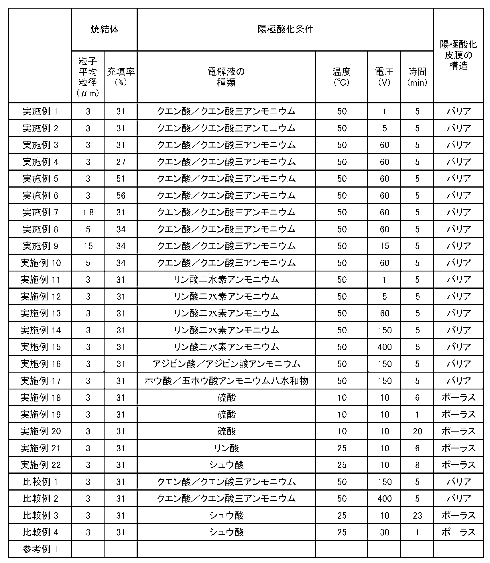
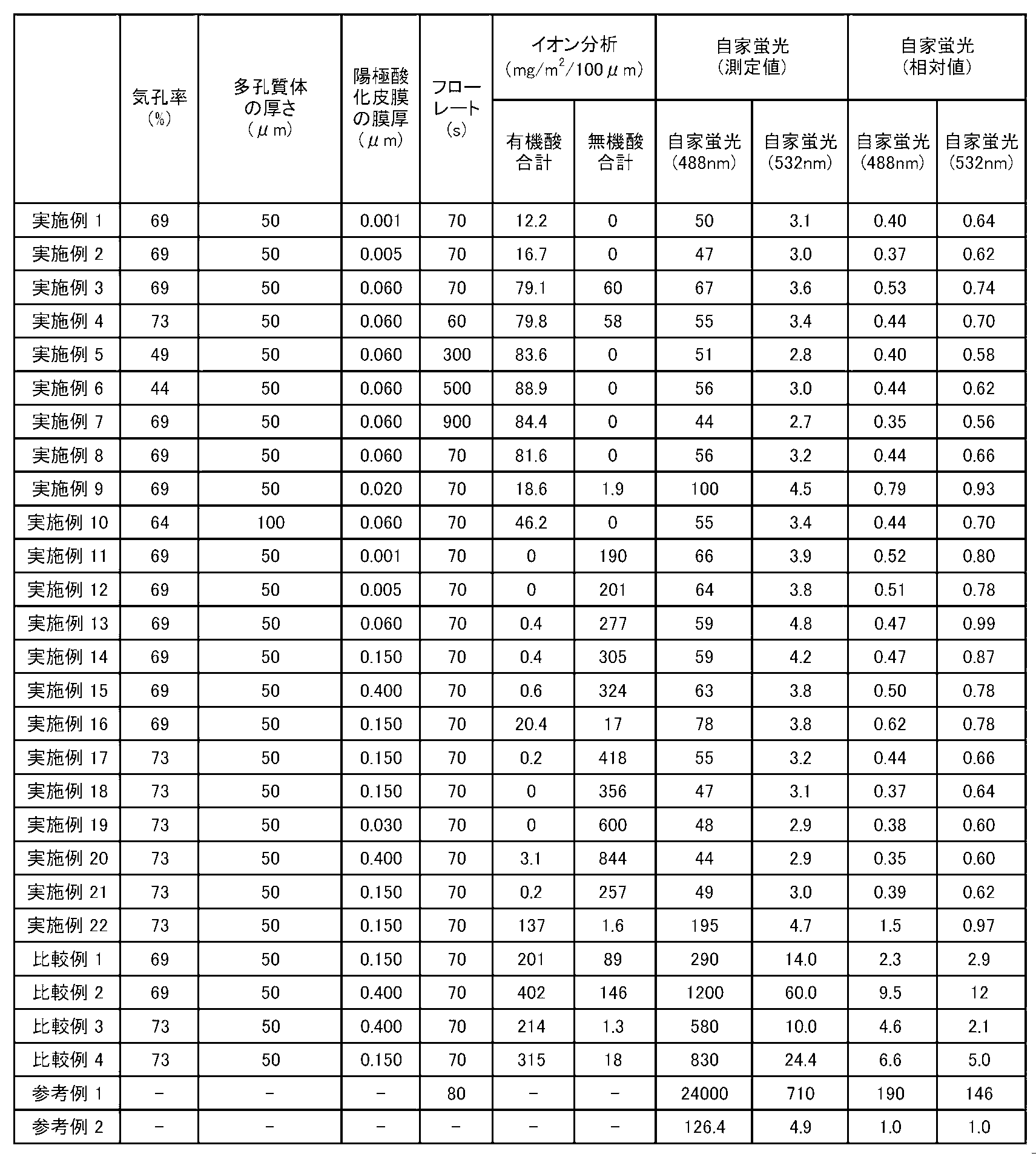

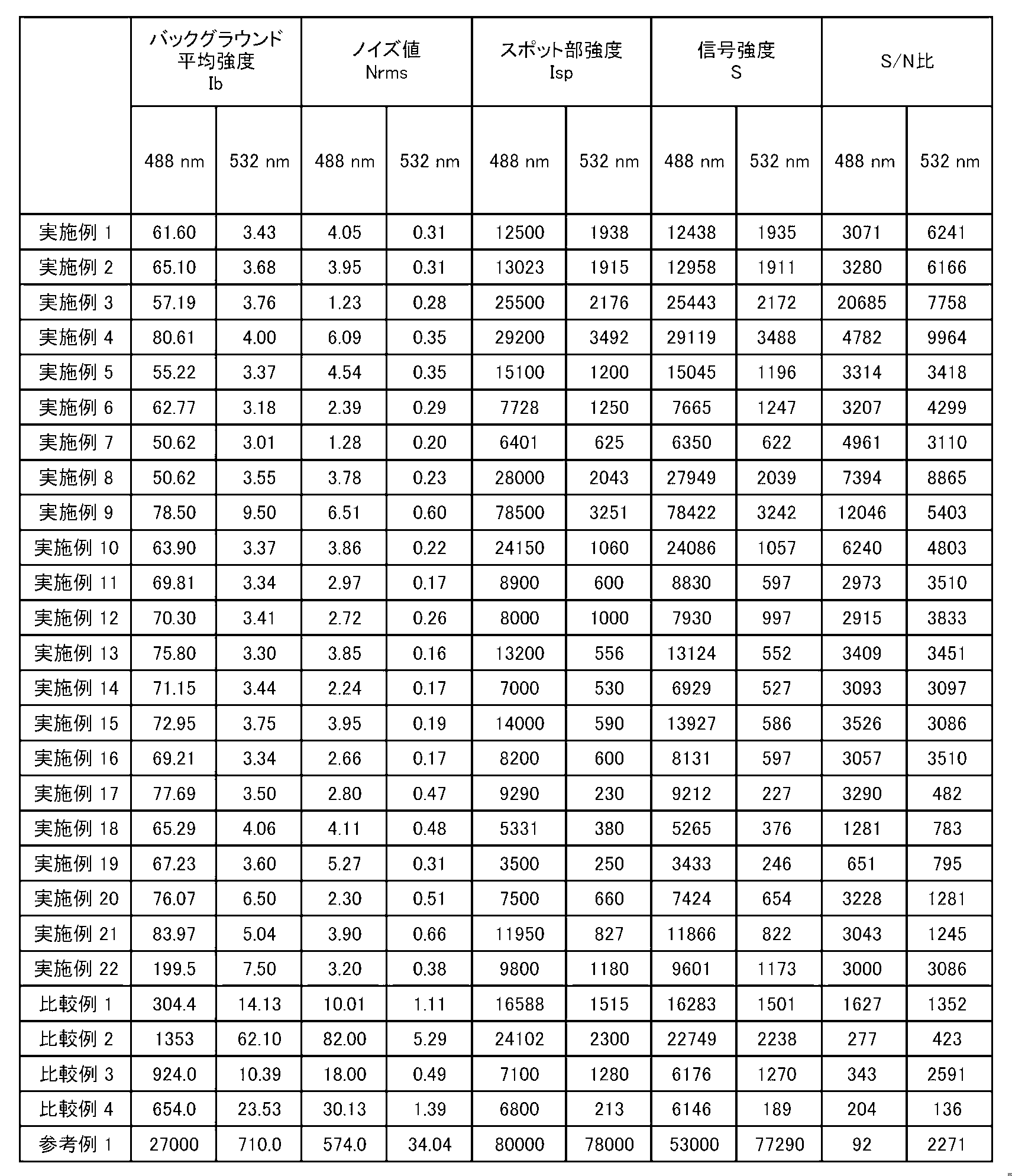
[検討]
図8は、全有機酸濃度と自家蛍光強度との関係を示すグラフである。図9は、488nmの励起光を照射した場合の全無機酸濃度と自家蛍光強度との関係を示すグラフである。図8に示すように、全有機酸濃度と自家蛍光強度とは、相関関係が大きいことが確認できる。一方、図9に示すように、488nmの励起光を照射した場合の全無機酸濃度と自家蛍光強度とは、相関関係が小さいことが確認できる。
図8は、全有機酸濃度と自家蛍光強度との関係を示すグラフである。図9は、488nmの励起光を照射した場合の全無機酸濃度と自家蛍光強度との関係を示すグラフである。図8に示すように、全有機酸濃度と自家蛍光強度とは、相関関係が大きいことが確認できる。一方、図9に示すように、488nmの励起光を照射した場合の全無機酸濃度と自家蛍光強度とは、相関関係が小さいことが確認できる。
表4に示すように、実施例に係る分析用担体は、金属部材の有機酸濃度が150mg/m2/100μm以下であり、比較例に係る分析用担体は、金属部材の有機酸濃度が150mg/m2/100μmを超えている。そして、表4に示すように、実施例に係る分析用担体は、アルミニウム標準反射板との比較によって表される自家蛍光の相対値が、2.0を下回っていた。一方、比較例に係る分析用担体は、アルミニウム標準反射板との比較によって表される自家蛍光の相対値が、2.0を上回っていた。また、表6に示すように、実施例に係る分析用担体は、比較例に係る分析用担体と比較し、バックグラウンド平均強度及びノイズ値が低かった。このように、実施例に係る分析用担体は、分析用担体含まれる成分に由来する自家蛍光の信号が抑えられており、また、スポット部以外の領域から発せられる信号も抑えられていることが分かる。従って、実施例に係る分析用担体によれば、分析用担体に対して励起光を照射して出射光を検出する分析を行う際に、分析対象物に由来するスポット部からの信号を高感度で検出しやすくなることが分かる。
比較例1及び比較例2に係る分析用担体は、実施例1~実施例3に係る分析用担体と比較し、陽極酸化の電解電圧が高かったため、陽極酸化皮膜のバリア層が厚く形成され、陽極酸化皮膜に多くの有機酸又は有機酸由来物が取り込まれてしまったと考えられる。そのため、金属部材の有機酸濃度が150mg/m2/100μmを超え、自家蛍光が増加したのだと考えられる。
比較例3に係る分析用担体は、実施例22に係る分析用担体と比較し、陽極酸化の電解時間が長い。そのため、陽極酸化皮膜のポーラス層が厚く形成され、陽極酸化皮膜に多くの有機酸又は有機酸由来物が取り込まれてしまったと考えられる。また、比較例4に係る分析用担体は、実施例22に係る分析用担体と比較し、陽極酸化の電解時間が短いものの、電解電圧が高い。そのため、陽極酸化皮膜のバリア層が厚く形成され、陽極酸化皮膜に多くの有機酸又は有機酸由来物が取り込まれてしまったと考えられる。この結果、金属部材の有機酸濃度が150mg/m2/100μmを超え、自家蛍光が増加したのだと考えられる。
また、実施例14、実施例16、実施例17及び比較例1の比較から、電解液にリン酸及びホウ酸のような無機酸を用いた場合、並びに、アジピン酸を用いた場合には、クエン酸を用いた場合と比較して有機酸濃度が低くなることが分かった。また、実施例18~実施例21の結果から、硫酸及びリン酸のような無機酸を用いた場合も、有機酸濃度が低くなることが分かった。
さらに、実施例1~22に係る分析用担体に、488nmの励起光を照射した場合においては、参考例1のニトロセルロース製メンブレンフィルターと比較し、いずれも自家蛍光が低く、また、ノイズ値Nrmsが低いことで優れたS/N比を示すことが分かった。また、実施例1~実施例16及び実施例22に係る分析用担体に、532nmの励起光を照射した場合においても、参考例1のニトロセルロース製メンブレンフィルターと比較し、いずれも自家蛍光が低く、また、ノイズ値Nrmsが低いことで優れたS/N比を示すことが分かった。
532nmの励起光を照射した場合において、実施例1~16,22に係る分析用担体は、実施例17~21に係る分析用担体よりも、S/N比が高い傾向にあった。ここで、陽極酸化皮膜に残存する電解液の成分の影響によって、分析用担体への非特異的吸着の増加に伴うノイズ値の上昇、あるいは、陽極酸化皮膜に吸着する抗体や蛍光体の変性に伴う信号強度の低下が引き起こされる可能性が考えられる。実施例1~10,16,22のクエン酸、アジピン酸、シュウ酸といった有機酸を含む電解液を用いた分析用担体では、陽極酸化皮膜に残存する電解液の成分の影響によって引き起こされうるノイズ値の上昇や信号強度の低下が抑えられることで、S/N比が高くなっていたと考えられる。実施例11~15のリン酸二水素アンモニウムの電解液を用いて作製した分析用担体でも同様の理由から、S/N比が高くなっていたと考えられる。
特願2023-096908号(出願日:2023年6月13日)の全内容は、ここに援用される。
以上、本実施形態を実施例及び比較例によって説明したが、本実施形態はこれらに限定されるものではなく、本実施形態の要旨の範囲内で種々の変形が可能である。
本開示によれば、自家蛍光を抑制することが可能な分析用担体、分析用担体の製造方法、及び分析用担体を用いた分析方法を提供することができる。
1 分析用担体
10 金属部材
20 多孔質体
21 アルミニウム粒子
22 骨格
23 空隙
24 外殻
10 金属部材
20 多孔質体
21 アルミニウム粒子
22 骨格
23 空隙
24 外殻
Claims (15)
- 多孔質体を含む金属部材を備える分析用担体であって、
前記多孔質体は、複数のアルミニウム粒子が集合して形成される骨格と、前記骨格に囲まれる複数の空隙とを含み、
前記骨格は、前記アルミニウム粒子の表面に、酸化アルミニウムを含む陽極酸化皮膜を含む外殻を有し、
前記多孔質体の気孔率は30体積%以上であり、
前記複数のアルミニウム粒子の平均粒子径は0.1μm~20μmであり、
前記金属部材の有機酸濃度は150mg/m2/100μm以下である、分析用担体。 - 前記陽極酸化皮膜は有機酸陽極酸化皮膜である、請求項1に記載の分析用担体。
- 前記陽極酸化皮膜は、クエン酸陽極酸化皮膜、アジピン酸陽極酸化皮膜、及びシュウ酸陽極酸化皮膜からなる群から選ばれる少なくとも一種である、請求項1又は2に記載の分析用担体。
- 前記陽極酸化皮膜は、硫酸陽極酸化皮膜、リン酸陽極酸化皮膜、及びホウ酸陽極酸化皮膜からなる群から選ばれる少なくとも一種である、請求項1に記載の分析用担体。
- 前記陽極酸化皮膜は、クエン酸陽極酸化皮膜、アジピン酸陽極酸化皮膜、シュウ酸陽極酸化皮膜、リン酸陽極酸化皮膜、及びホウ酸陽極酸化皮膜からなる群から選ばれる少なくとも一種である、請求項1に記載の分析用担体。
- 前記陽極酸化皮膜は、弱酸陽極酸化皮膜である、請求項1~3及び5のいずれか一項に記載の分析用担体。
- 前記分析用担体は、前記分析用担体に対して励起光を照射することで発せられる蛍光を測定する蛍光分析を行うための分析用担体である、請求項1~6のいずれか一項に記載の分析用担体。
- 照射する前記励起光の波長は250nm~650nmであり、測定する前記蛍光の波長は350nm~700nmである、請求項7に記載の分析用担体。
- 多孔質体を含む金属部材を備える分析用担体の製造方法であって、
前記多孔質体は、複数のアルミニウム粒子が集合して形成される骨格と、前記骨格に囲まれる複数の空隙とを含み、
前記骨格は、前記アルミニウム粒子の表面に、酸化アルミニウムを含む陽極酸化皮膜を含む外殻を有し、
前記製造方法は、
複数のアルミニウム金属粒子を焼結し、焼結体を得る焼結工程と、
前記焼結体を陽極酸化し、前記アルミニウム金属粒子の表面に前記陽極酸化皮膜を含む前記外殻を形成する陽極酸化工程と、を含み、
前記複数のアルミニウム金属粒子の平均粒子径は0.1μm~20μmであり、
前記焼結体の充填率は20体積%~70体積%であり、
前記金属部材の有機酸濃度は150mg/m2/100μm以下である、分析用担体の製造方法。 - 前記陽極酸化工程では、有機酸を含む電解液を用いて焼結体を陽極酸化する、請求項9に記載の分析用担体の製造方法。
- 前記陽極酸化工程では、クエン酸、アジピン酸、及びシュウ酸、並びにこれらの塩からなる群より選ばれる少なくとも一種を含む電解液を用いて焼結体を陽極酸化する、請求項9又は10に記載の分析用担体の製造方法。
- 前記陽極酸化工程では、硫酸、リン酸、及びホウ酸、並びにこれらの塩からなる群より選ばれる少なくとも一種を含む電解液を用いて焼結体を陽極酸化する、請求項9に記載の分析用担体の製造方法。
- 前記陽極酸化工程では、クエン酸、アジピン酸、シュウ酸、リン酸、及びホウ酸からなる群より選ばれる少なくとも一種の酸を含む電解液を用いて陽極酸化する、請求項9に記載の分析用担体の製造方法。
- 前記陽極酸化工程では、弱酸を含む電解液を用いて陽極酸化する、請求項9~11及び13のいずれか一項に記載の分析用担体の製造方法。
- 分析用担体に担持された分析対象物の分析を行う分析方法であって、
前記分析用担体は、
多孔質体を含む金属部材を備える分析用担体であって、
前記多孔質体は、複数のアルミニウム粒子が集合して形成される骨格と、前記骨格に囲まれる複数の空隙とを含み、
前記骨格は、前記アルミニウム粒子の表面に、酸化アルミニウムを含む陽極酸化皮膜を含む外殻を有し、
前記多孔質体の気孔率は30体積%以上であり、
前記複数のアルミニウム粒子の平均粒子径は0.1μm~20μmであり、
前記金属部材の有機酸濃度は150mg/m2/100μm以下であり、
前記分析方法は、
前記分析対象物を担持した状態の前記分析用担体に対して、紫外領域から赤外領域に含まれる少なくともいずれかの波長を有する光を照射する照射工程と、
前記照射された光の反射光、散乱光、透過光、蛍光、及び燐光からなる群より選ばれる少なくとも一種の光を検出する検出工程と、
を含む、分析方法。
Priority Applications (1)
| Application Number | Priority Date | Filing Date | Title |
|---|---|---|---|
| CN202480029625.2A CN121152974A (zh) | 2023-06-13 | 2024-06-10 | 分析用载体、分析用载体的制造方法、以及分析方法 |
Applications Claiming Priority (2)
| Application Number | Priority Date | Filing Date | Title |
|---|---|---|---|
| JP2023-096908 | 2023-06-13 | ||
| JP2023096908A JP2024178628A (ja) | 2023-06-13 | 2023-06-13 | 分析用担体、分析用担体の製造方法、及び分析方法 |
Publications (1)
| Publication Number | Publication Date |
|---|---|
| WO2024257718A1 true WO2024257718A1 (ja) | 2024-12-19 |
Family
ID=93851963
Family Applications (1)
| Application Number | Title | Priority Date | Filing Date |
|---|---|---|---|
| PCT/JP2024/021017 Ceased WO2024257718A1 (ja) | 2023-06-13 | 2024-06-10 | 分析用担体、分析用担体の製造方法、及び分析方法 |
Country Status (3)
| Country | Link |
|---|---|
| JP (1) | JP2024178628A (ja) |
| CN (1) | CN121152974A (ja) |
| WO (1) | WO2024257718A1 (ja) |
Cited By (1)
| Publication number | Priority date | Publication date | Assignee | Title |
|---|---|---|---|---|
| WO2025205371A1 (ja) * | 2024-03-29 | 2025-10-02 | 日本軽金属株式会社 | 分析用担体、イムノクロマトグラフィー用テストストリップ及び分析用担体の製造方法 |
Citations (6)
| Publication number | Priority date | Publication date | Assignee | Title |
|---|---|---|---|---|
| JP2007121234A (ja) * | 2005-10-31 | 2007-05-17 | Toa Denka:Kk | 検知センサ |
| JP2009085889A (ja) * | 2007-10-02 | 2009-04-23 | Canon Inc | マイクロカラムの製造方法 |
| JP2010223655A (ja) * | 2009-03-23 | 2010-10-07 | Panasonic Corp | センサおよびシーケンサー |
| WO2013027777A1 (ja) * | 2011-08-23 | 2013-02-28 | 東洋アルミニウム株式会社 | バイオチップ用基板及びその製造方法 |
| WO2020059728A1 (ja) * | 2018-09-19 | 2020-03-26 | 日本軽金属株式会社 | アルミニウム部材及びその製造方法 |
| WO2021079813A1 (ja) * | 2019-10-21 | 2021-04-29 | 日本軽金属株式会社 | アルミニウム部材、イムノクロマトグラフィー用テストストリップ及びアルミニウム部材の製造方法 |
-
2023
- 2023-06-13 JP JP2023096908A patent/JP2024178628A/ja active Pending
-
2024
- 2024-06-10 WO PCT/JP2024/021017 patent/WO2024257718A1/ja not_active Ceased
- 2024-06-10 CN CN202480029625.2A patent/CN121152974A/zh active Pending
Patent Citations (6)
| Publication number | Priority date | Publication date | Assignee | Title |
|---|---|---|---|---|
| JP2007121234A (ja) * | 2005-10-31 | 2007-05-17 | Toa Denka:Kk | 検知センサ |
| JP2009085889A (ja) * | 2007-10-02 | 2009-04-23 | Canon Inc | マイクロカラムの製造方法 |
| JP2010223655A (ja) * | 2009-03-23 | 2010-10-07 | Panasonic Corp | センサおよびシーケンサー |
| WO2013027777A1 (ja) * | 2011-08-23 | 2013-02-28 | 東洋アルミニウム株式会社 | バイオチップ用基板及びその製造方法 |
| WO2020059728A1 (ja) * | 2018-09-19 | 2020-03-26 | 日本軽金属株式会社 | アルミニウム部材及びその製造方法 |
| WO2021079813A1 (ja) * | 2019-10-21 | 2021-04-29 | 日本軽金属株式会社 | アルミニウム部材、イムノクロマトグラフィー用テストストリップ及びアルミニウム部材の製造方法 |
Cited By (1)
| Publication number | Priority date | Publication date | Assignee | Title |
|---|---|---|---|---|
| WO2025205371A1 (ja) * | 2024-03-29 | 2025-10-02 | 日本軽金属株式会社 | 分析用担体、イムノクロマトグラフィー用テストストリップ及び分析用担体の製造方法 |
Also Published As
| Publication number | Publication date |
|---|---|
| CN121152974A (zh) | 2025-12-16 |
| JP2024178628A (ja) | 2024-12-25 |
Similar Documents
| Publication | Publication Date | Title |
|---|---|---|
| JP7827329B2 (ja) | 万能増強剤としての超高輝度蛍光ナノコンストラクト | |
| TWI899108B (zh) | 鋁構件、免疫層析用測試條以及鋁構件的製造方法 | |
| EP3321666B1 (en) | Thermal contrast assay and reader | |
| CN102507953B (zh) | 一种测定甲胎蛋白的电化学免疫传感器的制备方法 | |
| JP7563515B2 (ja) | アルミニウム部材及びその製造方法 | |
| CN111295580B (zh) | 使用光致发光颗粒的超灵敏检测方法 | |
| JPS6226423B2 (ja) | ||
| Rostgaard et al. | Vertical nanowire arrays as a versatile platform for protein detection and analysis | |
| JP5342584B2 (ja) | ラテラルフロー用テストストリップ | |
| KR102051345B1 (ko) | 제어된 사이즈의 금 나노입자를 이용한 측면 흐름 분석-기반 바이오센서 및 b형 간염 바이러스를 진단하는 방법 | |
| JP7438183B2 (ja) | フォトルミネッセンス無機ナノ粒子を使用した毛細管現象試験 | |
| WO2013185167A1 (en) | Metallic nanoparticle treated cellulosic substrate as a sers biodiagnostic platform | |
| JP2024178628A (ja) | 分析用担体、分析用担体の製造方法、及び分析方法 | |
| Shao et al. | A dual signal-amplified electrochemiluminescence immunosensor based on core-shell CeO2-Au@ Pt nanosphere for procalcitonin detection | |
| EP4127716B1 (en) | Composite particles for biologic assay | |
| CN203705455U (zh) | 一种带有条形码贴片的测试片 | |
| JP2011528114A (ja) | 分析試験要素およびその作成方法 | |
| JP2025154854A (ja) | 分析用担体、イムノクロマトグラフィー用テストストリップ及び分析用担体の製造方法 | |
| JP2025154856A (ja) | 分析用担体、イムノクロマトグラフィー用テストストリップ及び分析用担体の製造方法 | |
| CN116794288A (zh) | 一种光子晶体荧光免疫家庭检测试条及其制备方法和应用 | |
| JP6633978B2 (ja) | 検査キット及び検査方法 | |
| CN120927966A (zh) | 一种集成侧向和垂直流的微流控免疫分析芯片及其分析方法 | |
| KR20260022649A (ko) | 라만분광표지자가 표면에 기능화된 나노채널을 가진 Ag-AAO 표면강화 라만분광기판 및 이의 제조방법 | |
| Qasim | Environmental and Medical Applications of Molecularly Imprinting Polymer Sensor for the Detection of Progesterone | |
| WO2004023120A1 (ja) | 発光型ナノチャンネルセンサー |
Legal Events
| Date | Code | Title | Description |
|---|---|---|---|
| 121 | Ep: the epo has been informed by wipo that ep was designated in this application |
Ref document number: 24823334 Country of ref document: EP Kind code of ref document: A1 |
|
| NENP | Non-entry into the national phase |
Ref country code: DE |