WO2024257693A1 - 摩擦接合における耐力増強構造 - Google Patents
摩擦接合における耐力増強構造 Download PDFInfo
- Publication number
- WO2024257693A1 WO2024257693A1 PCT/JP2024/020796 JP2024020796W WO2024257693A1 WO 2024257693 A1 WO2024257693 A1 WO 2024257693A1 JP 2024020796 W JP2024020796 W JP 2024020796W WO 2024257693 A1 WO2024257693 A1 WO 2024257693A1
- Authority
- WO
- WIPO (PCT)
- Prior art keywords
- bolt
- splice
- strength
- friction
- force
- Prior art date
- Legal status (The legal status is an assumption and is not a legal conclusion. Google has not performed a legal analysis and makes no representation as to the accuracy of the status listed.)
- Ceased
Links
Images








Classifications
-
- F—MECHANICAL ENGINEERING; LIGHTING; HEATING; WEAPONS; BLASTING
- F16—ENGINEERING ELEMENTS AND UNITS; GENERAL MEASURES FOR PRODUCING AND MAINTAINING EFFECTIVE FUNCTIONING OF MACHINES OR INSTALLATIONS; THERMAL INSULATION IN GENERAL
- F16B—DEVICES FOR FASTENING OR SECURING CONSTRUCTIONAL ELEMENTS OR MACHINE PARTS TOGETHER, e.g. NAILS, BOLTS, CIRCLIPS, CLAMPS, CLIPS OR WEDGES; JOINTS OR JOINTING
- F16B5/00—Joining sheets or plates, e.g. panels, to one another or to strips or bars parallel to them
- F16B5/02—Joining sheets or plates, e.g. panels, to one another or to strips or bars parallel to them by means of fastening members using screw-thread
Definitions
- the present invention relates to a strength-enhancing structure for friction joints.
- Fastener joints are a mechanical joining method in which holes are drilled in the components to be joined and force is transmitted by fasteners inserted into the holes.
- fastener joints There are three types of fastener joints depending on the method of force transmission: rivet joints, bolt joints and high-strength bolt joints.
- Joints using high-strength bolts are generally friction joints and are distinguished from shear joints which are governed by the shear force of the bolt. The important thing is the slip resistance, or how much force a friction joint can withstand without slipping. If the repeated stress is below the slip resistance, there will be no change in the bolt tension or the friction surface.
- the compressive stress distribution on the joint plane will govern the slip resistance.
- the joint base material will slide and come into contact with the bolt axis, and the shear force of the bolt will support the slipping. Therefore, in friction joints using high-strength bolts, the yield strength is improved by taking into account the yield strength of the base material.
- it is required, firstly, to keep in mind the slip resistance and obtain a wider compressive stress distribution even with the same compressive force.
- high-strength bolts are required to have high tensile and shear resistance.
- friction joints are joints in which stress is transmitted by the frictional resistance between the joined materials, which is obtained by the large inter-material compressive force generated when a pair of joined base materials is fastened with a high-strength bolt and nut, and stress is transmitted through the inter-material compressive force that is widely distributed around the bolt, and unlike rivet joints, which transmit stress through localized support pressure, there is little stress concentration and the flow of stress is smooth, so they are widely used.
- the objective of the present invention is to improve the strength of friction joint structures from a different perspective than conventional methods, and to provide a friction joint structure that further increases the strength.
- the present invention provides a friction joining structure in which the workpieces 10, 10 are joined together by screwing together a plurality of high-strength bolts and pressure-welding them, using a splice 11 as a support plate, and the workpieces 10, 10 are joined by frictional force generated at the contact surface between the splice and the workpieces,
- the splice plate 11 on the lower side of the workpiece 10 is made of a flat steel material of substantially the same material and thickness as the nuts to be screwed into the high strength bolts, and is configured by providing screw holes 11A to be screwed into the tip side screw portions 21 of the multiple high strength bolts;
- the high-strength bolt is inserted into the insertion hole 10A of the joined members, and then screwed into the screw hole 11A provided in the lower splice plate 11.
- This joining structure spreads the axial pressure distribution around where the high-strength bolt tip 21 and the screw hole 11A of the splice screw together with an influence cone that spreads from the head of the high-strength bolt to the contact surface with the splice 11, improving the slip resistance, and at the same time increasing the compression spring constant Kc to reduce the ratio ⁇ (bolt internal force coefficient) of the tensile internal force Ft added to the bolt when an external force Wa is applied to it, thereby improving the shear resistance of the high-strength bolt.
- the splice 11 comes in a pair, upper and lower, and the same is true when joining members 10, 10 to be joined.
- the splice plate is a friction joint that spreads over the entire joint surface with the joined members, so it is distinguished from the shear joint that relies on the shear force of the high-strength bolt in Patent Document 1, and it is considered that the pressure distribution form on the joint surface is changed from the double-headed cone of the bolt nut ( Figure 12A) to the single-headed cone of the bolt splice ( Figure 12B).
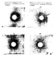
- Figures 16 (1) (2) and (3) (4) a phenomenon is observed in which the pressure distribution spreads around the bolt compared to the nut (compare Figures 16 (1) (2) and (3) (4)), and a greater slip resistance is obtained with the same tightening force.
- Figure 10D is a schematic diagram showing the fastened body of Figure 10A in the form of a spring, with an internal tensile force Ff indicated by A acting on the high-strength bolt shank, while a compressive force Ff indicated by B acts on the fastened object, showing a balanced state ( Figure 10C (a)).
- an external force Wa is applied here, an axial force Ft is applied to the high-strength bolt, while the compressive force of the fastened object is lost by Fc, and the tightening length extends by ⁇ .
- the tensile spring constant Kt and the compression spring constant Kc form a triangle with point A as the apex, where the tensile spring constant line Kt (from 0 to equilibrium point A) and the compression spring constant line Kc (from point D to line A) intersect at point A.
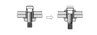
- a sleeve is fitted onto the bolt shank, the bolt is inserted into a hole in the joined member from the front side to the back side, a nut is screwed onto the bolt shank, and the nut is rotated and tightened to deform the sleeve into a brim shape between the bolt head and the joined member to prevent the bolt from falling out (Patent Document 2); as shown in FIG. 8, a sleeve is fitted onto the screw insertion hole of the joined member and the support plate, and the sleeve is deformed to prevent the bolt from falling out (Patent Document 3); and as shown in FIG.
- a back surface of the bolt head is formed into a tapered shape, and the tip of the sleeve is expanded by the back surface of the bolt head to prevent the bolt from falling out (Patent Document 4).
- Patent Document 4 a back surface of the bolt head is formed into a tapered shape, and the tip of the sleeve is expanded by the back surface of the bolt head to prevent the bolt from falling out.
- the part protruding downward from the support plate is plastically deformed by tightening the bolt to form a stopper to prevent the bolt from falling out, and there was a problem that sufficient compression force distribution was not obtained due to the lack of strength on the brim-shaped side, and the friction joint strength of the F10 standard was not achieved.
- the present invention provides a friction joint structure having increased strength and durability greater than the tightening strength of the conventional high-strength bolt and nut structure shown in FIG. 1A.
- a splice plate having dimensions based on the Building Standards Act in place of the conventional nut on the splice plate side, but if the splice plate is made of substantially the same material as the nut (for example, a heat-treated S45C or S33C splice plate is normally used for an F10T high-strength bolt, but Everhard C400LE steel (HRC30 ⁇ 2) may also be used, and the splice plate material may be changed depending on the high-strength bolt to be used, and an appropriate material may be selected), and is formed of a plate thickness substantially the same as that of the nut (here, substantially the same thickness means a thickness that does not interfere with fastening, and generally means the same as the nut thickness or preferably within a range of ⁇ 20%, more preferably within a range of ⁇ 10%), and a female thread is formed in the bolt insertion hole and screwed into the male thread at the tip of the high-stre
- the elasticity of the bolt becomes a tension spring represented by the spring A
- the elasticity of the joint member side becomes a compression spring represented by the spring B.
- the tension spring constant (load per unit elongation) of A is Kt
- the compression spring constant (load per unit elongation) of B is Kc
- the compression spring constant Kc when two plates are fastened with the threaded splice of the present invention is greater than the compression spring constant Kc when three plates are fastened with a conventional high-strength bolt and nut, and the load on the bolt is reduced.
- the above-mentioned effects can be achieved in the same manner in a normal bolt having a one-way thread formed in the screw hole 11A of the splice plate 11, and in a torque-type bolt having a reverse thread formed on the tip side and the base side where the pin tail is provided.
- the load on the bolt is limited, so that the tightening axial force prescribed by JIS S B1186 is not limited to F8T equivalent, and it is possible to provide a friction joint structure having slip resistance equal to or greater than that of a friction joint using a high-strength bolt and nut equivalent to F10T.
- FIG. 1B is a schematic diagram showing the fastener in the form of a spring. This shows a state in which a tensile force Ff indicated by A is applied to the high-strength bolt shank, while a compressive force Ff indicated by B is applied to the fastened object, and the two are in balance.
- FIG. 1B is a schematic diagram showing the fastener in the form of a spring. This shows a state in which a tensile force Ff indicated by A is applied to the high-strength bolt shank, while a compressive force Ff indicated by B is applied to the fastened object, and the two are in balance.
- FIG. 1B is a schematic diagram showing the fastener in the form of a spring. This shows a state in which a tensile force Ff indicated by A is applied to the high-strength bolt shank, while a compressive force Ff indicated by B is applied to the fastened object, and the two are in balance.
- FIG. 1B is
- FIG. 1B is an explanatory diagram showing a state in which the fastened object elongates by ⁇ when an external force Wa is applied to the state in which the tensile force Ff of the bolt shank of the fastener in FIG. 1A and the compressive force Ff of the fastened object are balanced (a).
- This is a tightening diagram in which the horizontal axis represents elongation (reduction in contraction of the tightened object) and the vertical axis represents axial force.
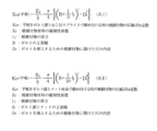
- the formula for calculating the compression spring constant of a conventional bolted fastener (Formula I) and the formula for calculating the spring constant of a bolted fastener of the present invention (Formula II) are shown below.
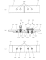
- FIG. 1A is a plan view of a preferred embodiment of a friction joining structure according to the present invention
- FIG. 1B is a front view of the embodiment
- FIG. 1C is a bottom view of the embodiment.
- FIG. 2 is a diagram showing a one-sided torque wrench type high strength bolt for friction joining in the embodiment.
- FIG. 2 is a perspective view showing the workpieces and a splice to be friction-joined in the embodiment.
- FIG. 4 is a perspective view showing a state midway through a joining process in the embodiment.
- 5 is a cross-sectional view showing a state midway through a joining step in the embodiment.
- FIG. FIG. 1 is a diagram showing a first example of a conventional one-sided friction joining structure.
- FIG. 1 is a diagram showing a first example of a conventional one-sided friction joining structure.
- FIG. 13 is a diagram showing a second example of a conventional one-sided friction joining structure.
- FIG. 13 is a diagram showing a third example of a conventional one-sided friction joining structure.
- 13A is a diagram showing a plan view, a partially cross-sectional side view, and a bottom view, respectively, of a friction joining structure in a second embodiment;
- FIG. 1 is a graph showing the change in load leading to breakage of a conventional friction joint.
- FIG. 13 is a cross-sectional explanatory view of a friction joint subjected to a test for compressive force distribution in a conventional friction joint.
- FIG. 2 is a cross-sectional explanatory view of a friction joint in which a compression force distribution test of the friction joint of the present invention was conducted.
- FIG. 1 is a side view showing the structures of test specimens of a conventional friction joint structure (a) and the friction joint structures of the present invention (b) and (c).
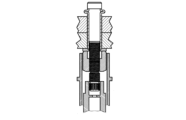
- 1A is a cross-sectional view of a conventional torque-type high-strength bolt in the middle of being fastened
- FIG. 1B is a cross-sectional view showing the state after fastening.
- 12B shows experimental results of the compression force distribution of the friction joint of the present invention at positions between the upper splice and the joined parts (1) and between the lower splice and the joined parts (2) in FIG. 12B, and experimental results of the compression force distribution of the conventional friction joint at positions between the upper splice and the joined parts (3) and between the lower splice and the joined parts (4) in FIG. 12A.
- Figures 2 to 6 show a preferred embodiment of the friction joint structure of the present invention.
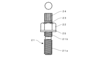
- the torque-type high-strength bolt used in the present invention is shown in Figure 3. That is, the friction joint bolt 20 is a bolt having a shape formed by forming a torque-stud type fracture groove 23 and a pin tail 24 on a stud bolt, and a left-handed thread 21a is formed on one half of the bolt, and a right-handed thread 21b is formed on the half on the pin tail 24 side, and a nut 22 is screwed onto the right-handed thread 21b.
- the part where the dish-shaped retaining head of the structural torque-type high-strength bolt ( Figure 15 (a)) having a pin tail and a right-handed thread was previously formed has a left-handed thread of the same nominal dimensions as the right-handed thread cut.
- the Torqueshape bolt 44 has a bolt shaft 44 with male threads that is inserted from the support plate 41 side to the joined member 40 side through an insertion hole to prevent it from falling out, so it has a round retaining head 44a on the head and is fastened with a nut 42.
- the one-sided high-strength bolt 20 used in this invention is inserted from the joined member 10 side and screwed into the female thread 11A of the support plate 11, so it has a new shape that does not have a retaining part on the head.
- the workpieces 10 to be joined by the friction joint bolts 20 have multiple insertion holes 10A for the friction joint bolts 20 formed at intervals, and the support plate 11 overlaid on the friction joint bolts 20 has multiple left-handed screw holes 11A formed at equal intervals as the insertion holes 10A of the workpieces 10.
- a support plate 11 is formed on the front side of the workpieces 10 in the same way as on the back side, no screw holes are provided in the front support plate, but instead insertion holes similar to the insertion holes 10A are provided ( Figures 14(b) and (c)).
- high-strength bolts are used for friction joining of steel structures with a structural torsion-type high-strength bolt 44, a hexagonal nut 42, and a set of washers 45. They are often used due to their excellent characteristics such as ease of installation using a torsion wrench and stability of the tightening axial force, and the installation method is shown in Figures 15(a), (b), and (c).
- a hexagonal nut 22 for a high-strength bolt is set on the pin tail 24 side of the friction joining bolt 20 as shown in Figure 3.
- the support plate 11 is placed on the underside of the workpiece 10, the workpiece 10 is inserted from the top of the workpiece 10 through the washer 25, and the left-hand screw 21 of the friction joint bolt 20 is screwed into the left-hand threaded bolt hole (left-hand screw hole) 11A of the support plate 11.
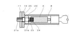
- the tightening of the friction-joint bolt 20 by the torque wrench to ensure the tightening axial force is performed in the following steps as shown in FIG. 1)
- the pintail 24 of the friction joint bolt 20 is gripped with the pintail gripping jig A at the core of the torque wrench, and when the nut 22 is stopped, it is rotated counterclockwise so that the tip 21 of the bolt screws into the screw hole 11A of the support plate 11 (see Figure 13 (a)).
- the friction-fastening bolt 20 is rotated counterclockwise so that the bearing surface of the splice plate 11 and the bearing surface of the nut 22 sandwich the fastened members 10 (see FIG. 13(b)).
- the pintail gripping jig A whose rotation has stopped, functions as a receiver for the reaction force caused by the rotation of the nut 22 (see FIG. 13(c)).
- the pintail gripping jig A stops, the nut gripping jig B rotates clockwise and the nut 22 tightens the workpieces 10, and when a predetermined tightening axial force is generated in the friction-joint bolt 20, the pintail 24 breaks in the groove 23 and tightening is completed (see FIG. 13(d)).
- the splice plate 11 is provided only on the back surface of the workpieces 10, but the same applies when a splice plate is provided on the front surface as well, so a description will be omitted.
- Figures 10(a), (b), and (c) show the second embodiment, which differs from the first embodiment in that a normal bolt is used in place of a torsion bolt. That is, the friction joint bolt 50 consists of a bolt head 51 and a bolt shaft 52, and a right-handed male thread 53 is formed on the bolt shaft 52.
- Through holes 10A for the friction joint bolts 50 are formed at intervals in the workpieces 10, and a support plate 11, which is placed on the back side of the friction joint bolts 50, has multiple left-handed female screw holes 11A formed at equal intervals as the through holes 10A in the workpieces 10.
- a support plate 11 When performing friction welding, as shown in FIG. 10(b), a support plate 11 is placed on the back side of the workpieces 10 to be joined, and the support plate 11 is inserted into the through hole 10A of the workpieces 10 from the front side of the workpieces 10 through a washer 54, and the male thread 53 of the friction welding bolt 50 is screwed into the right-hand threaded bolt hole (splice) 11A of the support plate 11.
- the friction joint bolt 50 is screwed in using a tool, and when a specified tightening force is reached, the joined members 10 are tightened between the right-hand thread 11A, which is spliced in place of a nut, and the head 51 of the hexagonal bolt 50, completing the friction joint.
- the bolt has a torque stud-type fracture groove and a pin tail
- the tip half of the bolt has a left-handed thread
- the pin tail half has a right-handed thread
- the present invention also includes a friction joint bolt in which the tip half of the torque stud-type bolt has a right-handed thread, and the pin tail half has a left-handed thread.
- the present invention also includes a friction-joint bolt in which a left-handed thread is formed on the bolt shank.
- One of the friction joint structures according to the present invention is a friction joint structure in which a workpiece 10 and a support plate 11 are joined by a bolt 20, in which a left-handed male thread 21 is formed in the tip half of the bolt shaft, a right-handed male thread 21a is formed in the base half of the bolt shaft, and a nut 22 is screwed into the right-handed male thread 21b of the base half, while an insertion hole 10A for the bolt is formed in the workpiece and a left-handed female thread 11A is formed in the support plate, and At the very least, the splice plate 11 is placed on the back side of the joined member 10, the left-handed male thread 21 of the bolt shaft is inserted into the through hole 10A from the front side of the joined member and screwed into the left-handed female thread 11A of the splice plate 11, the joined member is clamped between the splice plate and the nut as the nut is screwed, and the pin tail 24 of the bolt breaks, making it possible to fasten the joined member
- Another feature of the present invention is that a stud bolt with a Torxia-type breaking groove 23 and a pin tail 24 is used, a left-handed male thread 21a is formed on the tip half of the bolt, and a right-handed male thread 21b is formed on the pin tail half, a nut 22 is screwed into the right-handed male thread 21b, an insertion hole 10A is formed in the joined member 10, and a screw insertion hole 11A is formed in the support plate 11.
- the support plate 11 is placed on the underside of the joined member 10, the left-handed male thread 21a is inserted into the insertion hole 10A from the top of the joined member 10 and screwed into the screw hole 11A of the support plate 11, and when the nut 22 comes into contact with the joined member 10 by rotating the bolt counterclockwise, the nut 22 is then rotated clockwise to clamp the joined member 10, and the pin tail 24 is broken by a predetermined tightening axial force.
- a stud bolt with a torsion stud-type breaking groove 23 and a pin tail 24 When using a commercially available tool, such as a torsion wrench, it is advisable to use a stud bolt with a torsion stud-type breaking groove 23 and a pin tail 24, form a left-handed male thread 21a on one half of the bolt, and form a right-handed male thread 21b on the pin tail half, and screw a nut 22 onto the right-handed male thread 21b.
- a right-handed male thread 21b is formed on the pintail half of the bolt, and a left-handed male thread 21a is formed on the tip half, but it is also possible to form a left-handed male thread on the pintail half of the bolt, and a right-handed male thread on the tip half.
- a torque wrench type bolt is used in the above, a normal hexagonal bolt 50 as specified in JIS B1186, consisting of a head and a shaft, can also be used. That is, according to the present invention, in a friction joining structure in which the members to be joined 10 and the splice plate 11 of Figure 9 are joined by a bolt 22, a right-handed male thread 52 is formed on the shank of the bolt 50, an insertion hole 10A of the bolt shank is formed in the members to be joined, a right-handed female thread 11A is formed in the splice plate 11, the splice plate 11 is superimposed on the back side of the members to be joined 10, the right-handed male thread 52 of the bolt 50 is inserted into the insertion hole 10A from the front side of the members to be joined 10 and screwed into the female thread 11A of the splice plate 11, the members to be joined 11 are clamped between the splice plate 11 and the bolt head 51 as the bolt head 51 of the bolt 50 threads forward, and the
- the friction joining method described above is also novel. That is, in the friction joining method according to the present invention, when overlapping the workpieces 10 and the support plate 11 and friction-joining them with a bolt, a stud bolt 20 having a torque stud-type fracture groove 23 and a pin tail 24 is used as the bolt, a left-handed or right-handed male thread 21a is formed in the tip half of the bolt shaft, a right-handed or left-handed male thread 21b is formed in the pin tail half, a nut 22 is screwed into the right-handed or left-handed male thread 21b, and an insertion hole 10A for the bolt is formed in the workpieces 10 and the support plate 11 is friction-joined with the bolt.
- a left-handed female thread 11A is formed in 11, the splice plate 11 is placed on the back side of the joined member 10, the left-handed male thread 21a of the bolt 20 is inserted into the insertion hole 10A from the front side of the joined member 10 and screwed into the female thread 11A of the splice plate 11, the bolt 22 is rotated by gripping the pin tail 24, and when the nut 22 comes into contact with the joining member 10, the nut 22 is rotated, and the pin tail 24 is broken by the reaction force of the tightening, making it possible to tighten between the splice plate 11 and the nut 22 with a predetermined tightening axial force.
- threaded splices are also novel.
- the shortest length of thread engagement between a steel bolt and a threaded splice that does not cause shear fracture of the threads is investigated. Consideration of shear fracture of threads of steel female threads If the minimum shear load of the threads of the female thread is greater than the maximum tensile fracture load of the female thread, the threads of the female thread will not shear fracture. As a result of calculating this inequality with general conditions, for bolts larger than M12, the minimum fit length Lmin is 60% of the nominal diameter.
- Invention 1 As test specimens for a sliding test of an F10 bolt specified in JIS B1186 and a threaded splice plate (S45C), a joined member 10 (SS400, thickness 18 mm) and a splice plate 11 (S45C, thickness 12 mm) were used as test specimens, as shown in FIG. 14(b).
- Tightening method Primary tightening: Pass a hexagonal bolt with a washer through the bolt hole of the threaded support plate, screw the bolt into the screw hole of the threaded support plate installed on the back of the component, and perform the primary tightening of the bolt head with a preset torque wrench determined for each nominal diameter. (Tighten with the bolt head) Marking Mark the bolt head, washer and parts. The bolt head is tightened with a precision of 120 degrees ⁇ 30 degrees using a rotation angle controlled power tightening device.
- Invention 2 Slip test of right- and left-handed thread pin-tail type bolt set As a test specimen, a joined member (SS400, thickness 18 mm) 10 and a splice plate (S45C, thickness 12 mm) as shown in FIG. 14(c) were used. Tightening procedure: A double-threaded pintail bolt with a nut for final tightening screwed into the left-handed bolt hole of the threaded support plate is passed through and the bolt's threads are screwed into the left-handed threaded hole of the threaded support plate installed on the back of the part to be tightened. Grasp the pintail and nut with a commercially available torque wrench and rotate the pintail to the left.
- results of measuring the slip coefficient for various combinations 1) The slip coefficient of the F10 bolt and nut set specified in JIS B1186 is 0.73. 2) The slip coefficient of the F10 bolt and threaded support plate specified in JIS B1186 is 0.71. 3) The slip coefficient of the left and right thread pintail type bolt set is 0.48.
Landscapes
- Engineering & Computer Science (AREA)
- General Engineering & Computer Science (AREA)
- Mechanical Engineering (AREA)
- Joining Of Building Structures In Genera (AREA)
- Connection Of Plates (AREA)
Priority Applications (1)
| Application Number | Priority Date | Filing Date | Title |
|---|---|---|---|
| JP2025527881A JPWO2024257693A1 (https=) | 2023-06-10 | 2024-06-06 |
Applications Claiming Priority (2)
| Application Number | Priority Date | Filing Date | Title |
|---|---|---|---|
| JPPCT/JP2023/021636 | 2023-06-10 | ||
| JP2023021636 | 2023-06-10 |
Publications (1)
| Publication Number | Publication Date |
|---|---|
| WO2024257693A1 true WO2024257693A1 (ja) | 2024-12-19 |
Family
ID=93851867
Family Applications (1)
| Application Number | Title | Priority Date | Filing Date |
|---|---|---|---|
| PCT/JP2024/020796 Ceased WO2024257693A1 (ja) | 2023-06-10 | 2024-06-06 | 摩擦接合における耐力増強構造 |
Country Status (2)
| Country | Link |
|---|---|
| JP (1) | JPWO2024257693A1 (https=) |
| WO (1) | WO2024257693A1 (https=) |
Citations (4)
| Publication number | Priority date | Publication date | Assignee | Title |
|---|---|---|---|---|
| JPS6157217U (https=) * | 1984-09-21 | 1986-04-17 | ||
| JP2007032834A (ja) * | 2005-06-24 | 2007-02-08 | Nippon Steel Corp | 高力ボルト接合部 |
| CN103671379A (zh) * | 2013-12-18 | 2014-03-26 | 南京工业大学 | 高强度螺栓内螺纹连接结构 |
| JP2023113399A (ja) * | 2022-02-03 | 2023-08-16 | 濱中ナット株式会社 | 摩擦接合用添板 |
-
2024
- 2024-06-06 WO PCT/JP2024/020796 patent/WO2024257693A1/ja not_active Ceased
- 2024-06-06 JP JP2025527881A patent/JPWO2024257693A1/ja active Pending
Patent Citations (4)
| Publication number | Priority date | Publication date | Assignee | Title |
|---|---|---|---|---|
| JPS6157217U (https=) * | 1984-09-21 | 1986-04-17 | ||
| JP2007032834A (ja) * | 2005-06-24 | 2007-02-08 | Nippon Steel Corp | 高力ボルト接合部 |
| CN103671379A (zh) * | 2013-12-18 | 2014-03-26 | 南京工业大学 | 高强度螺栓内螺纹连接结构 |
| JP2023113399A (ja) * | 2022-02-03 | 2023-08-16 | 濱中ナット株式会社 | 摩擦接合用添板 |
Also Published As
| Publication number | Publication date |
|---|---|
| JPWO2024257693A1 (https=) | 2024-12-19 |
Similar Documents
| Publication | Publication Date | Title |
|---|---|---|
| Sønstabø et al. | Macroscopic strength and failure properties of flow-drill screw connections | |
| Boldsaikhan et al. | Refill friction stir spot welding of surface-treated aerospace aluminum alloys with faying-surface sealant | |
| US12129881B2 (en) | Preload controlled stud lockbolt | |
| AU2011287295B2 (en) | Apparatus for tightening threaded fasteners | |
| JP2005522641A5 (https=) | ||
| US6872041B2 (en) | Oversized wrenching head tension control bolt | |
| WO2024257693A1 (ja) | 摩擦接合における耐力増強構造 | |
| JP2023113399A (ja) | 摩擦接合用添板 | |
| US20210301854A1 (en) | Blind Fastener | |
| JP2011226625A (ja) | ワンサイドボルト | |
| JP7667977B2 (ja) | ブラインドファスナー | |
| CA2828676A1 (en) | Torque-angle structural fastening system | |
| EP3728875B1 (en) | Fastener assembly | |
| US11512729B2 (en) | Fastener assembly | |
| US20140048299A1 (en) | Torque-Angle Structural Fastening System | |
| JP2007032834A (ja) | 高力ボルト接合部 | |
| JPH05575Y2 (https=) | ||
| JPH08177837A (ja) | 回転防止装置付き高強度トルク型ブラインドボルト | |
| JP2010071383A (ja) | 高力ボルト摩擦接合構造及び高力ボルト摩擦接合方法 | |
| JP2025169696A (ja) | 締結具及びナット | |
| Wu et al. | Self-Tapping Screw Performance in Aluminum-Steel Joints | |
| JP2021042827A (ja) | 圧接方法 | |
| JPH0719227A (ja) | 支圧接合用組合せボルト及びその施工方法 | |
| JP2006283138A (ja) | アルミニウム又はアルミニウム合金材及びそれを使用した構造体 | |
| JPS638324B2 (https=) |
Legal Events
| Date | Code | Title | Description |
|---|---|---|---|
| 121 | Ep: the epo has been informed by wipo that ep was designated in this application |
Ref document number: 24823309 Country of ref document: EP Kind code of ref document: A1 |
|
| WWE | Wipo information: entry into national phase |
Ref document number: 2025527881 Country of ref document: JP |
|
| NENP | Non-entry into the national phase |
Ref country code: DE |