WO2024257621A1 - 電力変換器の制御装置、プログラム - Google Patents
電力変換器の制御装置、プログラム Download PDFInfo
- Publication number
- WO2024257621A1 WO2024257621A1 PCT/JP2024/019898 JP2024019898W WO2024257621A1 WO 2024257621 A1 WO2024257621 A1 WO 2024257621A1 JP 2024019898 W JP2024019898 W JP 2024019898W WO 2024257621 A1 WO2024257621 A1 WO 2024257621A1
- Authority
- WO
- WIPO (PCT)
- Prior art keywords
- axis
- target
- current
- field
- calculation unit
- Prior art date
- Legal status (The legal status is an assumption and is not a legal conclusion. Google has not performed a legal analysis and makes no representation as to the accuracy of the status listed.)
- Ceased
Links
Images











Classifications
-
- H—ELECTRICITY
- H02—GENERATION; CONVERSION OR DISTRIBUTION OF ELECTRIC POWER
- H02P—CONTROL OR REGULATION OF ELECTRIC MOTORS, ELECTRIC GENERATORS OR DYNAMO-ELECTRIC CONVERTERS; CONTROLLING TRANSFORMERS, REACTORS OR CHOKE COILS
- H02P21/00—Arrangements or methods for the control of electric machines by vector control, e.g. by control of field orientation
- H02P21/22—Current control, e.g. using a current control loop
-
- H—ELECTRICITY
- H02—GENERATION; CONVERSION OR DISTRIBUTION OF ELECTRIC POWER
- H02P—CONTROL OR REGULATION OF ELECTRIC MOTORS, ELECTRIC GENERATORS OR DYNAMO-ELECTRIC CONVERTERS; CONTROLLING TRANSFORMERS, REACTORS OR CHOKE COILS
- H02P27/00—Arrangements or methods for the control of AC motors characterised by the kind of supply voltage
- H02P27/04—Arrangements or methods for the control of AC motors characterised by the kind of supply voltage using variable-frequency supply voltage, e.g. inverter or converter supply voltage
- H02P27/06—Arrangements or methods for the control of AC motors characterised by the kind of supply voltage using variable-frequency supply voltage, e.g. inverter or converter supply voltage using DC to AC converters or inverters
-
- H—ELECTRICITY
- H02—GENERATION; CONVERSION OR DISTRIBUTION OF ELECTRIC POWER
- H02P—CONTROL OR REGULATION OF ELECTRIC MOTORS, ELECTRIC GENERATORS OR DYNAMO-ELECTRIC CONVERTERS; CONTROLLING TRANSFORMERS, REACTORS OR CHOKE COILS
- H02P29/00—Arrangements for regulating or controlling electric motors, appropriate for both AC and DC motors
- H02P29/60—Controlling or determining the temperature of the motor or of the drive
Definitions
- This disclosure relates to a power converter control device and a program.
- a conventional system includes a power storage unit, a power converter electrically connected to the power storage unit, and a rotating electric machine having an armature winding electrically connected to the power converter.
- a control device applied to this system performs switching control of the power converter to set the q-axis current flowing through the armature winding to zero while passing a d-axis current through the armature winding. This increases the temperature of the power storage unit while maintaining the rotor of the rotating electric machine in a stopped state.
- An example of such a control device is the control device disclosed in Patent Document 1.
- Noise and vibration can be a problem when heat is generated by switching control of the power converter while the rotor is kept stopped.
- the primary objective of this disclosure is to provide a power converter control device and program that can improve noise and vibration when heat is generated by switching control of the power converter while maintaining a stopped state of rotation of the rotor of a rotating electric machine.
- the present disclosure relates to a power storage device, a rotating electric machine having a rotor and an armature winding; a power converter electrically connecting the power storage unit and the armature winding and having upper and lower arm switches; At least one pair of gears that constitute a power transmission mechanism from the rotor to a rotationally driven object and that rotate by the rotational power from the rotor and mesh with each other;
- a control device for a power converter applied to a system including: a target value calculation unit for calculating d-axis and q-axis target currents to be applied to the armature windings; an armature control unit that controls a d-axis current flowing through the armature winding to correspond to the calculated d-axis target current, and controls switching of the upper and lower arm switches to control a q-axis current flowing through the armature winding to correspond to the calculated q-axis target current; Equipped with The target value calculation unit calculates the d- and q-axis target current
- the d-axis current flowing through the armature winding is controlled to the d-axis target current
- the q-axis current flowing through the armature winding is controlled to the q-axis target current by switching control of the upper and lower arm switches that constitute the power converter.
- the d- and q-axis target currents are calculated to satisfy the condition that the torque generated by the rotor is a torque that can maintain the rotor stopped.
- the system includes at least a pair of gears that form a power transmission path from the rotor to the rotationally driven object.
- the pair of gears mesh with each other and rotate due to the rotational power from the rotor.
- the pair of gears have backlash.
- the polarity of the torque generated by the rotor alternates between positive and negative due to the switching control described above, the direction of rotation of the gears alternates, which can cause gear teeth to rattle. In this case, even though the rotor remains stopped, gear teeth rattle. If the gear teeth rattle, the noise caused by the rattle worsens the noise level of the system.
- the d- and q-axis target currents are calculated so as to satisfy the condition that the time average value of the torque generated by the rotating electric machine in one or more cycles of the AC current flowing through the armature winding is offset from 0. This makes it possible to suppress the occurrence of rattle noise by maintaining the teeth of a pair of gears pressed against each other, and to reduce the rattle noise even if it does occur. As a result, it is possible to improve NV.
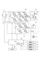
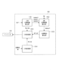
- FIG. 1 is a diagram showing an overall configuration of an in-vehicle system according to a first embodiment.
- FIG. 2 is a diagram showing an outline of a cooling system as a heat transfer unit;
- FIG. 3 is a diagram showing a state of teeth striking a gear according to a comparative example;
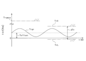
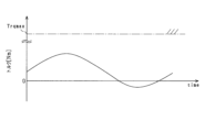
- FIG. 4 is a time chart showing a schematic diagram of a transition of torque generated by a rotor according to a comparative example;
- FIG. 5 is a time chart showing a schematic transition of torque generated by the rotor according to the first embodiment;
- FIG. 6 is a diagram showing a manner in which gear teeth strike is prevented;
- FIG. 1 is a diagram showing an overall configuration of an in-vehicle system according to a first embodiment.
- FIG. 2 is a diagram showing an outline of a cooling system as a heat transfer unit
- FIG. 3 is a diagram showing a state of teeth striking a gear according to a comparative example
- FIG. 4 is a time chart showing
- FIG. 7 is a time chart showing a transition of the rotor rotation angle during temperature increase control according to the first embodiment and a comparative example;
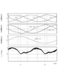
- FIG. 8 is a time chart showing changes in three-phase AC current, d-axis and q-axis currents, and field current during temperature rise control.
- FIG. 9 is a block diagram of the temperature rise control;
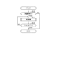
- FIG. 10 is a flowchart showing a procedure for controlling temperature rise.
- FIG. 11 is a flowchart showing a procedure for controlling temperature rise.
- FIG. 12 is a time chart showing a gradual change processing mode according to the second embodiment;
- FIG. 13 is a block diagram of an initial target value calculation unit;
- FIG. 14 is a block diagram of a termination target value calculation unit;
- FIG. 15 is a diagram showing the overall configuration of an in-vehicle system according to a third embodiment
- FIG. 16 is a time chart showing the transition of the d-axis and q-axis target currents.
- FIG. 17 is a time chart showing the transition of the d-axis and q-axis target currents.
- FIG. 18 is a block diagram of the temperature rise control;
- FIG. 19 is a flowchart showing a procedure for controlling temperature rise.
- FIG. 20 is a time chart showing changes in d-axis and q-axis target currents according to the fourth embodiment;
- FIG. 21 is a time chart showing a schematic diagram of a transition of torque generated by a rotor according to another embodiment;
- FIG. 22 is a time chart showing a schematic diagram of the transition of torque generated by a rotor according to another embodiment.
- a system including a control device according to the present embodiment is mounted on a vehicle such as an electric vehicle or a hybrid vehicle.
- the system includes a storage battery 10 (corresponding to the "energy storage unit"), two power converters, and a rotating electric machine 30.
- the rotating electric machine 30 is a wound field type rotating electric machine.
- the rotating electric machine 30 in this embodiment is a rotating electric machine having forward salient polarity, which is a characteristic in which the d-axis inductance Ld is larger than the q-axis inductance Lq.
- the storage battery 10 is, for example, a battery pack including a series connection of unit batteries.
- the unit battery is a single battery cell or a series connection of multiple battery cells.
- the battery cell is, for example, a secondary battery such as a lithium-ion battery.
- the storage battery 10 can be charged by an external charger provided outside the vehicle.
- the external charger is, for example, a stationary charger.
- the rotating electric machine 30 is a device that applies rotational power to the drive wheels 12 (corresponding to the "rotationally driven object") of the vehicle to rotate the drive wheels 12.
- the rotating electric machine 30 includes a rotor 31.
- the rotor 31 includes a rotor core and a plurality of field salient poles extending radially from the rotor core.
- a field winding 32 is wound around each field salient pole.
- the rotating shaft of the rotor 31 is capable of transmitting power to the drive wheels 12 of the vehicle via a power transmission mechanism 11 provided in the system.
- the torque generated by the rotating electric machine 30 functioning as an electric motor is transmitted to the drive wheels 12 via the power transmission mechanism 11, causing the drive wheels 12 to rotate. This causes the vehicle to run.
- the rotating electric machine 30 may be, for example, an in-wheel motor that is integrally provided with the drive wheels 12 of the vehicle, or an on-board motor that is provided on the body of the vehicle.
- the power transmission mechanism 11 includes a transmission and a shaft.
- the transmission is, for example, a reduction gear and includes at least a pair of gears (see Figures 3 and 6).
- the transmission includes a first gear 13 and a second gear 14.
- the first gear 13 and the second gear 14 are meshed with each other and are rotatable around a central axis of rotation that extends in a predetermined direction.
- the rotating electric machine 30 includes a stator 33.
- the stator 33 includes an armature core and an armature winding.
- the armature core includes an annular back yoke portion and a number of teeth extending radially from the back yoke portion toward the rotor 31.
- the armature winding includes U-, V-, and W-phase windings 34U, 34V, and 34W that are star-connected with an electrical angle of 120° from each other.
- the system includes an inverter 20 (corresponding to the "first power converter") and a field current circuit 40 (corresponding to the "second power converter”).
- the inverter 20 converts DC current from the storage battery 10 into AC current and supplies it to the armature winding.
- the inverter 20 includes a series connection of U-, V-, and W-phase upper arm switches SUH, SVH, and SWH, and U-, V-, and W-phase lower arm switches SUL, SVL, and SWL.
- each of the switches SUH, SVH, SWH, SUL, SVL, and SWL is an N-channel MOSFET.
- Each of the switches SUH, SVH, SWH, SUL, SVL, and SWL includes a body diode DUH, DVH, DWH, DUL, DVL, and DWL.
- the positive terminal of the storage battery 10 is connected to the drain, which is the high-potential side terminal of the U-, V-, and W-phase upper arm switches SUH, SVH, and SWH, via a high-potential side electrical path Lp.
- the negative terminal of the storage battery 10 is connected to the source, which is the low-potential side terminal of the U-, V-, and W-phase lower arm switches SUL, SVL, and SWL, via a low-potential side electrical path Ln.
- Each electrical path Lp, Ln is a conductive member such as a bus bar.
- the inverter 20 is equipped with a first capacitor 21, which is a smoothing capacitor.
- the first capacitor 21 may be provided outside the inverter 20.
- the field energization circuit 40 supplies current from the storage battery 10 to the field winding 32.
- the field energization circuit 40 is a full bridge circuit and includes a series connection of a first upper arm switch SH1 and a first lower arm switch SL1, and a series connection of a second upper arm switch SH2 and a second lower arm switch SL2.
- each of the switches SH1, SH2, SL1, and SL2 is an N-channel MOSFET.
- Each of the switches SH1, SH2, SL1, and SL2 includes a body diode DH1, DH2, DL1, and DL2.
- Each of the switches SH1, SH2, SL1, and SL2 is a bidirectional conductive switching element that allows current to flow from drain to source and from source to drain when turned on.
- the drain which is the high potential terminal of the first and second upper arm switches SH1 and SH2, is connected to the positive terminal of the storage battery 10 via the high potential electrical path Lp.
- the source which is the low potential terminal of the first and second lower arm switches SL1 and SL2, is connected to the negative terminal of the storage battery 10 via the low potential electrical path Ln.
- a first end of the field winding 32 is connected to the connection point between the first upper arm switch SH1 and the first lower arm switch SL1 via a brush (not shown).
- a second end of the field winding 32 is connected to the connection point between the second upper arm switch SH2 and the second lower arm switch SL2 via a brush (not shown).
- the field current circuit 40 includes a second capacitor 41, which is a smoothing capacitor.
- the second capacitor 41 may be provided outside the field current circuit 40. Also, instead of a configuration in which the second capacitor 41 is provided separately in the field energizing circuit 40 and the first capacitor 21 is provided separately in the inverter 20, a configuration in which a common capacitor is provided in the inverter 20 and the field energizing circuit 40 may be used. In this case, for example, a configuration in which the second capacitor 41 is not provided may be used.
- the system includes a device for cooling the inverter 20, the field current circuit 40, the rotating electric machine 30, and the storage battery 10 when switching control of the inverter 20 is being performed to run the vehicle.
- the vehicle includes a circulation path 400 through which the coolant circulates, an electric water pump 401, a radiator 402, and an electric fan 403.
- the water pump 401 circulates the coolant by being driven by power supply.
- the inverter 20, the field current circuit 40, the rotating electric machine 30, and the storage battery 10 are arranged in this order on the downstream side of the water pump 401 in the circulation path 400. Note that the arrangement order in the circulation path 400 is not limited to the order shown in FIG. 2.
- a radiator 402 is provided between the water pump 401 and the storage battery 10 in the circulation path 400.
- the radiator 402 cools the cooling water flowing in through the circulation path 400 and supplies it to the water pump 401.
- the cooling water flowing into the radiator 402 is cooled by the wind blown against the radiator 402 as the vehicle travels, or by the wind blown against the radiator 402 by rotating and driving the fan 403.
- the water pump 401 and the fan 403 can be driven by a control device other than the control device 60. However, in this embodiment, for the sake of convenience, it is assumed that the water pump 401 and the fan 403 are driven by the control device 60 provided in the system.
- the system includes a voltage sensor 50, a phase current sensor 51, a field current sensor 52, an angle sensor 53, a battery temperature sensor 54, and a coolant temperature sensor 55.
- the voltage sensor 50 detects the voltage of the storage battery 10.
- the phase current sensor 51 detects the phase current flowing in at least two of the U-, V-, and W-phase windings 34U, 34V, and 34W.
- the field current sensor 52 detects the field current flowing in the field winding 32.
- the angle sensor 53 detects the rotation angle (specifically, the electrical angle) of the rotor 31.
- the battery temperature sensor 54 detects the temperature of the storage battery 10.
- the coolant temperature sensor 55 detects the temperature of the coolant flowing in the circulation path 400.
- the system includes a control device 60 and a higher-level control device 80 that is higher-level than the control device 60.
- the detection values of the sensors 50 to 55 are input to the control device 60.
- the control device 60 is an electronic control unit (Electronic Control Unit) that is mainly composed of a microcomputer 60a.
- the higher-level control device 80 is an electronic control unit (Electronic Control Unit) that is mainly composed of a microcomputer.
- the control device 60 and the higher-level control device 80 are capable of exchanging information.
- the microcomputer 60a includes a CPU (Central Processing Unit).
- the functions provided by the microcomputer 60a can be provided by software recorded in a physical memory device and a computer that executes the software, by software alone, by hardware alone, or by a combination of these.
- the microcomputer 60a when the microcomputer 60a is provided by an electronic circuit that is hardware, it can be provided by a digital circuit including a large number of logic circuits, or by an analog circuit.
- the microcomputer 60a executes a program stored in a non-transitory tangible storage medium that serves as a storage unit provided in the microcomputer 60a.
- the program includes, for example, programs for the processes shown in Figures 9 to 11, which will be described later.
- a method corresponding to the program is executed by executing a set of instructions that constitute the program.
- the storage unit is, for example, a non-volatile memory.
- the program stored in the storage unit can be updated via a communication network such as the Internet, for example, over the air (OTA).
- OTA
- the control device 60 performs switching control of each switch constituting the field current circuit 40 in order to excite the field winding 32. More specifically, the control device 60 performs switching control so that a first state and a second state alternate in order to control the field current Ifr detected by the field current sensor 52 to the field target current If*.
- the first state is a state in which the first upper arm switch SH1 and the second lower arm switch SL2 are turned on, and the second upper arm switch SH2 and the first lower arm switch SL1 are turned off.
- the second state is a state in which the first upper arm switch SH1 and the second lower arm switch SL2 are turned off, and the second upper arm switch SH2 and the first lower arm switch SL1 are turned on.
- the control device 60 When the field winding 32 is excited, the control device 60 performs switching control of each switch constituting the inverter 20 to feedback control the control amount of the rotating electric machine 30 to a command value based on the detection values of each sensor 50-55.
- the control amount is torque.
- the upper arm switch and the lower arm switch are alternately turned on. This feedback control transmits the rotational power of the rotor 31 to the drive wheels 12, causing the vehicle to run.
- This control is a control that generates heat by switching control of the inverter 20 and the field current circuit 40 when the temperature Tr of the storage battery 10 detected by the battery temperature sensor 54 falls below the target temperature T* when the storage battery 10 is charged by an external charger while the vehicle is stopped.
- the generated heat is transferred to the storage battery 10 via the cooling water circulating through the circulation path 400 by driving the water pump 401.
- the temperature rise control is continued, for example, until the temperature Tr of the storage battery 10 reaches the target temperature T*.
- the driving of the water pump 401 is continued at least while the temperature rise control is being executed.
- the circulation path 400, the cooling water circulating through the circulation path 400, and the water pump 401 correspond to the "heat transfer section".
- the temperature rise control quickly raises the temperature of the storage battery 10, thereby shortening the charging time of the storage battery 10 by the external charger.
- the control device 60 performs switching control of the inverter 20 so that sinusoidal d- and q-axis currents flow through the armature windings during the temperature rise control. At this time, in order to keep the rotor 31 in a rotation-stopped state and to keep the vehicle stationary, the control device 60 performs switching control of the field current circuit 40 so that the reluctance torque generated by the flow of the d- and q-axis currents is reduced by the magnet torque.
- FIG. 3 shows an example of an external gear as each of the gears 13, 14.
- Trqr generated by the rotor 31 alternates between positive and negative as shown in FIG. 4 due to switching control of the inverter 20 in the temperature rise control
- Trqmax in FIG. 4 is a torque threshold value.
- the torque threshold value Trqmax is the torque at which the drive wheels 12 start to rotate, and is set to, for example, the upper limit value of the range assumed as the torque at which the drive wheels 12 start to rotate.
- TrH and TrL in FIG. 4 are upper and lower limit values that define the torque width ⁇ Tr that keeps the NV characteristic values (e.g., noise, vibration) generated by the temperature rise control below the allowable value.
- the inverter 20 and the field current circuit 40 are switched to satisfy the condition that the time average value of the generated torque Trqr in one or more cycles of the AC current flowing through the armature winding is offset from 0 by an offset value Toffset.
- the teeth 13a of the first gear 13 and the teeth 14a of the second gear 14 are kept pressed against each other to suppress the generation of rattle noise and improve noise immunity.
- the torque Trq generated by the wound-field type rotating electric machine 30 is composed of magnet torque TM and reluctance torque TR, as expressed by the following equation (eq1).
- P indicates the number of pole pairs of the rotating electric machine 30, and ⁇ f indicates the magnetic flux generated by the field current flowing through the field winding 32.
- the control device 60 performs switching control of the inverter 20 so that sinusoidal three-phase AC currents IU, IV, IW, which are shifted in phase by 120 electrical degrees, flow through the windings 34U to 34W.
- sinusoidal d-axis and q-axis currents Id and Iq flow.
- the frequencies of the d-axis and q-axis currents Id and Iq are the same, and the phase difference between the d-axis current Id and the q-axis current Iq is 90 electrical degrees.
- the left side of the above equation (eq1) is set to the offset value Toffset, which leads to the following equation (eq2).
- the offset value Toffset is set to a value such that the generated torque of the rotor 31 is equal to or less than the torque threshold value Trqmax.
- Toffset P ⁇ f ⁇ Iq+P ⁇ (Ld ⁇ Lq) ⁇ Id ⁇ Iq...(eq2)
- ⁇ f Lmf ⁇ If.
- Lmf (>0) is a coupling inductance including the back yoke portion and teeth portion of the stator 33 and the rotor core and field salient pole portion of the rotor 31. is the inductance of the d-axis magnetic path.
- the control device 60 calculates a sinusoidal field target current If*.
- the control device 60 also calculates a sinusoidal q-axis target current Iq* that has a phase difference of 90 degrees with the field target current If*.
- the control device 60 calculates a d-axis target current Id* based on the calculated field target current If* and q-axis target current Iq* and the above equation (eq3).
- the target currents If*, Iq*, and Id* have the same frequency, and the phase difference between the d-axis target current Id* and the field target current If* is 180 degrees.
- the polarity of the second term on the right-hand side of the above equation (eq3) which includes the offset value Toffset, changes every time the polarity of the q-axis target current Iq* changes.
- t1 is the timing when the polarity of the q-axis target current Iq* changes from positive to negative
- t2 is the timing when the polarity of the q-axis target current Iq* changes from negative to positive
- the d-axis target current Id* has a waveform such that the magnitude of the d-axis target current Id* is offset in the increasing direction when the polarity of the q-axis target current Iq* changes.
- FIG. 9 shows a block diagram of the temperature rise control executed by the control device 60.
- the three-phase target amplitude calculation unit 61 acquires the target heat quantity Q* from the upper control device 80 for each control period, and calculates the amplitude Iuamp* of the U-phase target current, the amplitude Ivamp* of the V-phase target current, and the amplitude Iwamp* of the W-phase target current based on the acquired target heat quantity Q*.
- Each amplitude Iuamp*, Ivamp*, Iwamp* has the same value.
- the three-phase target amplitude calculation unit 61 calculates each amplitude Iuamp*, Ivamp*, Iwamp* to be larger the larger the target heat quantity Q*.
- the three-phase target amplitude calculation unit 61 may calculate each amplitude Iuamp*, Ivamp*, Iwamp* based on, for example, map information relating the target heat quantity Q* and each amplitude Iuamp*, Ivamp*, Iwamp*, and the acquired target heat quantity Q*.
- the target heat quantity Q* is, for example, a target value for the amount of heat [W] generated per unit time by each switch SUH, SUL, SVH, SVL, SWH, and SWL in response to switching control of each switch SUH, SUL, SVH, SVL, SWH, and SWL of the inverter 20.
- the two-phase target amplitude calculation unit 62 converts the amplitudes Iuamp*, Ivamp*, Iwamp* of the currents of each phase in the three-phase fixed coordinate system into the amplitude Idamp* of the d-axis target current Id* and the amplitude Iqamp* of the q-axis target current Iq* in the two-phase rotating coordinate system (dq coordinate system) for each control period based on the amplitudes Iuamp*, Ivamp*, Iwamp* of the currents of each phase and the electrical angle ⁇ e detected by the angle sensor 53.
- the target q-axis current calculation unit 63 calculates the sinusoidal q-axis target current Iq* having the amplitude Iqamp* of the q-axis target current Iq* calculated by the two-phase target amplitude calculation unit 62.
- the target q-axis current calculation unit 63 calculates the q-axis target current Iq*, for example, using the following equation (eq4).
- ⁇ is each frequency
- t is the elapsed time from the reference timing.
- the two-phase conversion unit 64 converts U-, V-, and W-phase currents in the three-phase fixed coordinate system into a dq coordinate system based on the detection value of the phase current sensor 51 and the detected electrical angle ⁇ e for each control period.
- the d-axis current Idr and the q-axis current Iqr are converted into
- the target field calculation unit 65 calculates a sinusoidal field target current If* that is out of phase with the q-axis target current Iq* by 90 degrees and has the same frequency as the q-axis target current Iq*, based on the amplitude Idamp* of the d-axis target current Id* calculated by the two-phase target amplitude calculation unit 62 for each control period.
- the target field calculation unit 65 calculates the field target current If*, for example, based on the amplitude Idamp* of the d-axis target current Id* and the following equation (eq5).
- the frequency of the field target current If* is set to a frequency that satisfies the control responsiveness of the field current Ifr, for example, a frequency of 5 Hz or more or 10 Hz or more and 30 or 40 Hz or less.
- the field control unit 66 generates gate drive signals for the switches SH1, SL1, SH2, and SL2 of the field current supply circuit 40 to feedback control the detected field current Ifr to the field target current If* calculated by the target field calculation unit 65.
- the field control unit 66 outputs the generated gate drive signals to the drive circuits that drive the switches SH1, SL1, SH2, and SL2. This controls the field current Ifr to the sinusoidal field target current If*.
- the target d-axis current calculation unit 67 calculates the d-axis target current Id* for each control period based on the field target current If* calculated by the target field calculation unit 65, the q-axis target current Iq* calculated by the target q-axis current calculation unit 63, and the above equation (eq3).
- the phase difference between the d-axis target current Id* and the field target current If* is 180 degrees.
- the target d-axis current calculation unit 67 and the target q-axis current calculation unit 63 correspond to the "target value calculation unit".
- the target d-axis current calculation unit 67 is provided with a limiter, and when the absolute value of the second term on the right side exceeds the limit value, the limiter sets the absolute value of the second term on the right side as the limit value.
- the limit value may be set to, for example, "0.05 x Ip ⁇ limit value ⁇ 0.25 x Ip", “0.1 x Ip ⁇ limit value ⁇ 0.2 x Ip", “0.05 x Ip ⁇ limit value ⁇ 0.15 x Ip", or "0.08 x Ip ⁇ limit value ⁇ 0.12 x Ip". Even if the target d-axis current calculation unit 67 does not have a limiter, no inconvenience in control occurs.
- the three-phase control unit 68 functions as an "armature control unit” that generates gate drive signals for each switch SUH, SUL, SVH, SVL, SWH, and SWL of the inverter 20 to feedback control the q-axis current Iqr calculated by the two-phase conversion unit 64 to the calculated q-axis target current Iq*, and to feedback control the d-axis current Idr calculated by the two-phase conversion unit 64 to the d-axis target current Id* calculated by the target d-axis current calculation unit 67.
- the electrical angle ⁇ e and the power supply Vdc detected by the voltage sensor 50 are used.
- the three-phase control unit 68 outputs the generated gate drive signals to the drive circuits that drive the switches SUH, SUL, SVH, SVL, SWH, and SWL.
- the d-axis current Idr is controlled to a sinusoidal d-axis target current Id*
- the q-axis current Iqr is controlled to a sinusoidal q-axis target current Iq*.
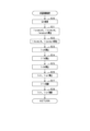
- FIG. 10 is a flowchart showing the procedure for the temperature rise control executed by the control device 60. This process is executed, for example, when the control device 60 determines that charging of the storage battery 10 by an external charger has started.
- step S10 it is determined whether there is a request to increase the temperature of the storage battery 10. In this embodiment, it is determined that there is a request to increase the temperature when the detected temperature Tr of the storage battery 10 is below the target temperature T*. Note that in this embodiment, the process of step S10 corresponds to the "determination unit.”
- step S10 If it is determined in step S10 that there is a temperature increase request, the process proceeds to step S11 and performs temperature increase control processing.
- step S12 it is determined whether the temperature Tobj of the object to be heated has reached the target temperature T*.
- the object to be heated is the storage battery 10, and therefore the temperature Tobj of the object to be heated is the temperature Tr of the storage battery 10.
- step S12 If it is determined in step S12 that the temperature Tr of the storage battery 10 is below the target temperature T*, the processing of step S11 is continued. On the other hand, if it is determined that the temperature Tr of the storage battery 10 has reached the target temperature T*, the temperature rise control is stopped. Incidentally, during the execution of the temperature rise control, the rotational drive of the fan 403 may be stopped in order to suppress a decrease in the temperature of the cooling water in the circulation path 400.
- step S11 The processing of step S11 will be explained using FIG. 11.
- step S20 the target heat quantity Q* is obtained from the upper control device 80.
- the upper control device 80 may calculate the target heat quantity Q* to be larger, for example, the larger the value obtained by subtracting the temperature Tr of the storage battery 10 from the target temperature T* is.
- step S21 the three-phase target amplitude calculation unit 61 calculates the amplitude Iuamp* of the U-phase target current, the amplitude Ivamp* of the V-phase target current, and the amplitude Iwamp* of the W-phase target current based on the target heat quantity Q* obtained in step S20.
- step S22 the two-phase target amplitude calculation unit 62 calculates the amplitude Idamp* of the d-axis target current Id* and the amplitude Iqamp* of the q-axis target current Iq* based on the amplitudes Iuamp*, Ivamp*, Iwamp* of the currents of each phase calculated in step S21 and the electrical angle ⁇ e.
- step S23 the target q-axis current calculation unit 63 calculates the q-axis target current Iq* based on the amplitude Iqamp* of the q-axis target current Iq* calculated in step S22.
- step S24 the target field calculation unit 65 calculates the field target current If* based on the amplitude Idamp* of the d-axis target current Id* calculated in step S22.
- step S25 the target d-axis current calculation unit 67 calculates the d-axis target current Id* based on the field target current If* calculated in step S24 and the q-axis target current Iq* calculated in step S23.
- step S26 the two-phase conversion unit 64 calculates the d-axis current Idr and the q-axis current Iqr based on the detection value of the phase current sensor 51 and the electrical angle ⁇ e.
- step S27 the field control unit 66 performs switching control of SH1, SL1, SH2, and SL2 of the field current supply circuit 40 to feedback control the field current Ifr to the field target current If* calculated in step S24.
- step S28 the three-phase control unit 68 performs feedback control of the d-axis current Idr calculated in step S26 to the d-axis target current Id* calculated in step S25, and performs switching control of each switch SUH, SUL, SVH, SVL, SWH, and SWL of the inverter 20 to feedback control the q-axis current Iqr calculated in step S26 to the q-axis target current Iq* calculated in step S23.
- the teeth 13a, 14a of the pair of gears 13, 14 can be kept pressed against each other to prevent the generation of teeth rattle noise.
- the rotating electric machine 30 may be a rotating electric machine having reverse salience, in which the q-axis inductance Lq is larger than the d-axis inductance Ld. In this case, the phase difference between the d-axis target current Id* and the field target current If* is 0 degrees.
- the control device 60 can vary the torque threshold value Trqmax. For example, when the control device 60 determines that the parking brake of the vehicle is in an engaged state, it sets the torque threshold value Trqmax to a value higher than when the parking brake is not in an engaged state.
- the control device 60 may also have an acquisition unit that acquires the temperature of the road surface on which the vehicle is traveling, and may change the torque threshold value Trqmax based on the acquired road surface temperature.
- map information that associates the road surface temperature with the torque threshold value Trqmax may be used.
- control device 60 may apply a braking torque to the vehicle's wheels using a mechanical brake device provided on the vehicle.
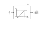
- the control device 60 includes an initial target value calculation unit 69A.
- the initial target value calculation unit 69A calculates initial d-axis and q-axis target currents Kt x Id* and Kt x Iq* and an initial field target current Kt x If*.
- the initial d-axis and q-axis target currents Kt x Id* and Kt x Iq* are the d-axis and q-axis target currents Id* and Iq* used in a first predetermined period from start timing t1 to timing t2 of the switching control of the inverter 20 by the three-phase control unit 68 and the switching control of the field energization circuit 40 by the field control unit 66.
- the initial field target current Kt x If* is the field target current If* used in the first predetermined period.
- the calculated initial d-axis and q-axis target currents Kt ⁇ Id* and Kt ⁇ Iq* are used in the three-phase control unit 68 , and the calculated initial field target current Kt ⁇ If* is used in the field control unit 66 .
- the initial target value calculation unit 69A sets the coefficient Kt to 0 at the start timing t1 of the first specified period, gradually increases the coefficient Kt towards 1 from the start timing t1 towards the end timing t2 of the first specified period, and sets the coefficient Kt to 1 after the end timing t2.
- the q-axis target current Iq* by which the coefficient Kt is multiplied is calculated by the target q-axis current calculation unit 63, and the d-axis target current Id* by which the coefficient Kt is multiplied is calculated by the target d-axis current calculation unit 67.
- the field target current If* by which the coefficient Kt is multiplied is calculated by the target field calculation unit 65.
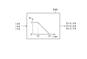
- the control device 60 is also provided with an end target value calculation unit 69B.
- the end target value calculation unit 69B calculates the end d- and q-axis target currents Kt ⁇ Id* and Kt ⁇ Iq* and the end field target current Kt ⁇ If*.
- the end d- and q-axis target currents Kt ⁇ Id* and Kt ⁇ Iq* are the d- and q-axis target currents Id* and Iq* used in a second predetermined period from timing t3, which is before the end timing t4 of the switching control of the inverter 20 by the three-phase control unit 68 and the switching control of the field current supply circuit 40 by the field control unit 66, to the end timing t4.
- the end field target current Kt ⁇ If* is the field target current If* used in the second predetermined period.
- the calculated end d-axis and q-axis target currents Kt x Id* and Kt x Iq* are used by the three-phase control unit 68, and the calculated end field target current Kt x If* is used by the field control unit 66.
- the end target value calculation unit 69B sets the coefficient Kt to 1 at the start timing t3 of the second specified period, gradually decreases the coefficient Kt toward 0 from the start timing t3 toward the end timing t4 of the second specified period, and sets the coefficient Kt to 0 after the end timing t4.
- the q-axis target current Iq* by which the coefficient Kt is multiplied is calculated by the target q-axis current calculation unit 63
- the d-axis target current Id* by which the coefficient Kt is multiplied is calculated by the target d-axis current calculation unit 67.
- the field target current If* by which the coefficient Kt is multiplied is calculated by the target field calculation unit 65.
- a rotating electric machine 30 is a permanent magnet field type rotating electric machine.
- the rotor 31 of the rotating electric machine 30 has a permanent magnet 35 (e.g., a neodymium magnet) as a field pole instead of the field winding 32 of the first embodiment. Therefore, the system of this embodiment does not have a field current circuit 40 and a field current sensor 52.
- a permanent magnet 35 e.g., a neodymium magnet
- the torque Trq generated by the permanent magnet field type rotating electric machine 30 is composed of magnet torque TM and reluctance torque TR, as expressed in the following equation (eq6).
- ⁇ m represents the magnetic flux generated by the permanent magnet 35.
- the left side of the above equation (eq6) is changed to the offset value Toffset, thereby deriving the following equation (eq7).
- the control device 60 of this embodiment calculates the d-axis target current Id*, which is a direct current.
- the control device 60 calculates the q-axis target current Iq* based on the calculated d-axis target current Id* and the above equation (eq8), so that the q-axis target current Iq* is also a direct current.
- the control device 60 calculates the d-axis and q-axis target currents Id* and Iq* according to each characteristic.
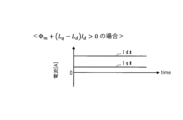
- the control device 60 calculates the d-axis and q-axis target currents Id* and Iq* that have the same polarity as each other, as shown in Fig. 16.
- a positive d-axis current indicates a strong field current
- a negative d-axis current indicates a weak field current
- the control device 60 calculates the d-axis target current Id* of the strong field.
- the control device 60 may calculate the d-axis target current Id* of the weak field instead of calculating the d-axis target current Id* of the strong field.
- control device 60 calculates d-axis and q-axis target currents Id* and Iq* that have opposite polarities as shown in Fig. 17.
- the control device 60 calculates the d-axis target current Id* of the strong field.
- the control device 60 may calculate the d-axis target current Id* of the weak field instead of calculating the d-axis target current Id* of the strong field.
- FIG. 18 shows a block diagram of the temperature rise control executed by the control device 60.
- the three-phase target amplitude calculation unit 161 acquires the target heat quantity Q* from the higher-level control device 80 for each control period, and calculates the amplitude Iuamp* of the U-phase target current, the amplitude Ivamp* of the V-phase target current, and the amplitude Iwamp* of the W-phase target current based on the acquired target heat quantity Q*.
- the two-phase target amplitude calculation unit 162 converts the amplitudes Iuamp*, Ivamp*, Iwamp* of the currents of each phase into the amplitude Idamp* of the d-axis target current Id* for each control period, similar to the two-phase target amplitude calculation unit 62 in FIG. 9, based on the amplitudes Iuamp*, Ivamp*, Iwamp* of the currents of each phase and the detected electrical angle ⁇ e.
- the target current calculation unit 163 calculates the d-axis target current Id* based on the amplitude Idamp* of the d-axis target current Id* calculated by the two-phase target amplitude calculation unit 162.
- the two-phase conversion unit 164 converts the U-, V-, and W-phase currents in the three-phase fixed coordinate system into the d-axis current Idr and the q-axis current Iqr in the dq coordinate system for each control period based on the detection value of the phase current sensor 51 and the detected electrical angle ⁇ e.
- the target current calculation unit 163 calculates the q-axis target current Iq* for each control period based on the calculated d-axis target current Id* and the above equation (eq8). In this embodiment, the target current calculation unit 163 corresponds to the "target value calculation unit.”
- the three-phase control unit 165 functions as an "armature control unit” that generates gate drive signals for each switch SUH, SUL, SVH, SVL, SWH, and SWL of the inverter 20 to feedback control the d-axis current Idr calculated by the two-phase conversion unit 164 to the calculated d-axis target current Id*, and to feedback control the q-axis current Iqr calculated by the two-phase conversion unit 164 to the calculated q-axis target current Iq*.
- the electrical angle ⁇ e and the power supply Vdc detected by the voltage sensor 50 are used.
- the three-phase control unit 165 outputs the generated gate drive signals to the drive circuits that drive each switch SUH, SUL, SVH, SVL, SWH, and SWL.
- the d-axis current Idr is controlled to the DC d-axis target current Id*
- the q-axis current Iqr is controlled to the DC q-axis target current Iq*.
- FIG. 19 is a flowchart showing the processing procedure for temperature rise control according to this embodiment, and corresponds to the processing shown in step S11 in FIG. 10.
- step S30 similar to step S20, the target heat quantity Q* is obtained from the upper control device 80.
- step S31 the three-phase target amplitude calculation unit 161 calculates the amplitude Iuamp* of the U-phase target current, the amplitude Ivamp* of the V-phase target current, and the amplitude Iwamp* of the W-phase target current based on the target heat quantity Q* obtained in step S30.
- step S32 the two-phase target amplitude calculation unit 162 calculates the amplitude Idamp* of the d-axis target current Id* based on the amplitudes Iuamp*, Ivamp*, Iwamp* of the currents of each phase calculated in step S31 and the electrical angle ⁇ e.
- step S33 the target current calculation unit 163 calculates the DC d-axis target current Id* based on the amplitude Idamp* of the d-axis target current Id* calculated in step S33.
- step S35 the two-phase conversion unit 164 calculates the d-axis current Idr and the q-axis current Iqr based on the detection value of the phase current sensor 51 and the electrical angle ⁇ e.
- step S36 the three-phase control unit 165 performs feedback control of the d-axis current Idr calculated in step S36 to the d-axis target current Id* calculated in step S33, and performs switching control of each switch SUH, SUL, SVH, SVL, SWH, and SWL of the inverter 20 to feedback control the q-axis current Iqr calculated in step S36 to the q-axis target current Iq* calculated in step S34.
- the teeth 13a, 14a of the pair of gears 13, 14 can be kept pressed against each other to prevent the generation of teeth rattle noise.
- the target current calculation unit 163 of the control device 60 of this embodiment calculates a sine-wave AC d-axis target current Id* instead of a DC current.
- the target current calculation unit 163 calculates a sine-wave d-axis target current Id* having an amplitude Idamp* of the d-axis target current Id* calculated by the two-phase target amplitude calculation unit 162.
- the target current calculation unit 163 calculates the d-axis target current Id* of, for example, the following equation (eq9).
- the target current calculation unit 163 calculates the q-axis target current Iq* based on the calculated d-axis target current Id* and the above equation (eq8). Since some of the current sources have the above characteristics, the target current calculation unit 163 calculates the d-axis and q-axis target currents Id* and Iq* according to the respective characteristics.
- the target current calculation unit 163 calculates a sinusoidal q-axis target current Iq* that is 180 degrees out of phase with the d-axis target current Id*, as shown in the upper part of FIG.
- the target current calculation unit 163 calculates a sine wave-shaped q-axis target current Iq* in phase with the d-axis target current Id*, as shown in the middle part of FIG.
- the temperature increase control in this embodiment is similar to the process shown in FIG.
- control device 60 of the fourth embodiment may calculate the sinusoidal d-axis target current Id* based on the sinusoidal q-axis target current Iq* and the above equation (eq11).
- the gradual change processing shown in Figures 12 to 14 may be performed.
- the temperature rise control of the third and fourth embodiments may be applied to a system equipped with a wound field type rotating electric machine in which the field current Ifr is a constant value.
- the d- and q-axis target currents Id* and Iq* and the field target current If* in the first and second embodiments, or the d- and q-axis target currents Id* and Iq* in the third and fourth embodiments may be calculated so as to satisfy the condition that the time average value of the generated torque over multiple periods of the AC current flowing through the armature winding is offset from 0 by the offset value Toffset.
- the condition that the time average value of the generated torque during multiple cycles of the AC current flowing through the armature winding is offset from 0 by the offset value Toffset can be satisfied. In this case, even if teeth striking occurs, it is possible to reduce the noise of teeth striking and the number of times teeth striking occurs.
- the rotating electric machine is not limited to a synchronous machine, but may be an asynchronous machine such as an induction machine.
- the rotating electric machine is not limited to a radial type in which the rotor and stator face each other in the radial direction, but may be an axial type in which the rotor and stator face each other in the axial direction of the rotating shaft.
- the rotating electric machine is not limited to star-connected machines, but may be delta-connected. Also, the rotating electric machine and inverter are not limited to three-phase machines, but may be two-phase machines or four or more phase machines.
- the object to be heated by the heating control may be, for example, the cooling water in the circulation path 400. If the vehicle is equipped with an air conditioning system that uses the cooling water as a heat source for heating the passenger compartment, the temperature of the heating heat source can be rapidly increased by the heating control.
- the heat transfer unit is not limited to one that uses cooling water as the cooling fluid, but may be, for example, an air-cooled type that uses gas (air) as the cooling fluid, or may be a metal heat sink.
- a heat sink is used as the heat transfer unit, for example, it is sufficient if a power converter such as an inverter and a storage battery are provided on the heat sink.
- the switch of the power converter is not limited to an N-channel MOSFET, but may be, for example, an IGBT. In this case, it is sufficient if a freewheel diode is connected in inverse parallel to the IGBT.
- the power storage unit connected to a power converter such as an inverter is not limited to a storage battery, but may be, for example, a large-capacity electric double-layer capacitor, or both a storage battery and an electric double-layer capacitor.
- the moving body on which the control device is mounted is not limited to a vehicle, but may be, for example, an airplane or a ship.
- the rotationally driven object is, for example, a propeller
- n is, for example, a screw.
- the object on which the control device is mounted is not limited to a moving body, but may be a stationary device.
- control device and method described in the present disclosure may be realized by a dedicated computer provided by configuring a processor and memory programmed to execute one or more functions embodied in a computer program.
- control device and method described in the present disclosure may be realized by a dedicated computer provided by configuring a processor with one or more dedicated hardware logic circuits.
- control device and method described in the present disclosure may be realized by one or more dedicated computers configured by combining a processor and memory programmed to execute one or more functions with a processor configured with one or more hardware logic circuits.
- the computer program may be stored in a computer-readable non-transient tangible recording medium as instructions executed by the computer.
- the rotating electric machine is a permanent magnet field type rotating electric machine including the rotor having a permanent magnet (35), or a wound field type rotating electric machine including the rotor having a field winding (32) through which a constant current flows, 2.
- the target value calculation unit (163) calculates the d- and q-axis target currents of DC so as to satisfy the first condition and the second condition.
- an initial target value calculation unit (69A) that calculates initial d- and q-axis target currents (Kt ⁇ Id*, Kt ⁇ Iq*) that are the d- and q-axis target currents used in a predetermined period from a start timing of the switching control by the armature control unit,
- the control device for a power converter according to any one of configurations 2 to 4, wherein the initial target value calculation unit gradually increases the initial d- and q-axis target currents from 0 toward the d- and q-axis target currents calculated by the target value calculation unit, during the predetermined period.
- a termination target value calculation unit (69B) that calculates termination d-axis and q-axis target currents (Kt ⁇ Id*, Kt ⁇ Iq*) that are the d-axis and q-axis target currents used in a predetermined period before a termination timing of the switching control by the armature control unit,
- the control device for a power converter according to any one of configurations 2 to 5, wherein the end target value calculation unit gradually reduces the end d- and q-axis target currents from the d- and q-axis target currents calculated by the target value calculation unit toward 0 during the predetermined period.
- the rotating electric machine is a wound field type rotating electric machine including the rotor having a field winding (32), the power converter is a first power converter;
- the system includes a second power converter (40) that electrically connects the power storage unit and the field winding, A target field calculation unit (65) that calculates a sinusoidal field target current (If*); a field control unit (66) that performs switching control of the second power converter so as to control a field current (Ifr) flowing through the field winding to the calculated field target current; Equipped with 2.
- [Configuration 8] The control device for a power converter according to configuration 7, wherein the target value calculation unit (63, 67) calculates the d-axis target current having a sinusoidal shape with a phase difference of 180 degrees or 0 degree with respect to the field target current so as to satisfy the first condition and the second condition.
- the target value calculation unit calculates the q-axis target current having a sine wave shape, and calculates the d-axis target current such that a magnitude of the d-axis current is offset in an increasing direction when a polarity of the q-axis target current is switched.
- an initial target value calculation unit (69A) that calculates initial d-, q-axis target currents (Kt ⁇ Id*, Kt ⁇ Iq*) that are the d-, q-axis target currents used in a predetermined period from a start timing of the switching control by the armature control unit, and an initial field target current (Kt ⁇ If*) that is the field target current used in the predetermined period,
- the control device for a power converter according to any one of configurations 7 to 9, wherein the initial target value calculation unit gradually increases the initial d- and q-axis target currents from 0 toward the d- and q-axis target currents calculated by the target value calculation unit, and gradually increases the initial field target current from 0 toward the field target current calculated by the target field calculation unit, during the predetermined period.
- a termination target value calculation unit (69B) for calculating termination d-, q-axis target currents (Kt ⁇ Id*, Kt ⁇ Iq*) which are the d-, q-axis target currents used in a predetermined period before a termination timing of the switching control by the armature control unit, and a termination field target current (Kt ⁇ If*) which is the field target current used in the predetermined period,
- the control device for a power converter according to any one of configurations 7 to 10, wherein the end target value calculation unit gradually decreases the end d- and q-axis target currents from the d- and q-axis target currents calculated by the target value calculation unit toward 0 during the specified period, and gradually decreases the end field target current from the field target current calculated by the target field calculation unit toward 0.
- the system is a system mounted on a vehicle, The control device for a power converter according to any one of configurations 1 to 11, wherein the armature control unit performs the switching control while the vehicle is stopped.
- the system includes a heat transfer unit (400, 401) that transfers heat generated in the power converter to a temperature-raising target (10), A determination unit that determines whether or not there is a temperature increase request for the temperature increase target, 13.
Landscapes
- Engineering & Computer Science (AREA)
- Power Engineering (AREA)
- Control Of Ac Motors In General (AREA)
Abstract
回転電機(30)のロータ(31)から回転駆動対象(12)までの動力伝達機構(11)を構成する一対のギア(13,14)を備えるシステムに制御装置(60)は適用される。制御装置は、電機子巻線(34U~34W)に流すd,q軸目標電流(Id*,Iq*)を算出する目標値算出部(63,67,163)と、d軸目標電流に電機子巻線に流れるd軸電流(Idr)を制御するとともに、q軸目標電流に電機子巻線に流れるq軸電流(Iqr)を制御すべく、電力変換器(20)のスイッチング制御を行う電機子制御部(68)と、を備える。目標値算出部は、ロータの発生トルクを、ロータの回転停止状態を維持可能なトルクにするとの第1条件、及び電機子巻線に流す交流電流の1周期又は複数周期における発生トルクの時間平均値を0からオフセットさせるとの第2条件を満たすように、d,q軸目標電流を算出する。
Description
本出願は、2023年6月14日に出願された日本出願番号2023-097686号に基づくもので、ここにその記載内容を援用する。
本開示は、電力変換器の制御装置、及びプログラムに関する。
従来、蓄電部と、蓄電部に電気的に接続された電力変換器と、電力変換器に電気的に接続された電機子巻線を有する回転電機とを備えるシステムが知られている。このシステムに適用される制御装置は、電力変換器のスイッチング制御を行うことにより、電機子巻線に流すq軸電流を0としつつ、電機子巻線にd軸電流を流す。これにより、回転電機のロータの回転停止状態を維持しつつ、蓄電部を昇温させる。なお、このような制御装置の例として、特許文献1に開示された制御装置が挙げられる。
ロータの回転停止状態を維持しつつ、電力変換器のスイッチング制御により熱を発生させる場合におけるNV(Noise,Vibration)が問題となり得る。
本開示は、回転電機のロータの回転停止状態を維持しつつ、電力変換器のスイッチング制御により熱を発生させる場合におけるNVを改善できる電力変換器の制御装置及びプログラムを提供することを主たる目的とする。
本開示は、蓄電部と、
ロータ及び電機子巻線を有する回転電機と、
前記蓄電部及び前記電機子巻線を電気的に接続し、上,下アームスイッチを有する電力変換器と、
前記ロータから回転駆動対象までの動力伝達機構を構成し、前記ロータからの回転動力によって回転するとともに互いに噛み合う少なくとも一対のギアと、
を備えるシステムに適用される電力変換器の制御装置において、
前記電機子巻線に流すd,q軸目標電流を算出する目標値算出部と、
算出された前記d軸目標電流に前記電機子巻線に流れるd軸電流を制御するとともに、算出された前記q軸目標電流に前記電機子巻線に流れるq軸電流を制御すべく、前記上,下アームスイッチのスイッチング制御を行う電機子制御部と、
を備え、
前記目標値算出部は、前記ロータの発生トルクを、前記ロータの回転停止状態を維持可能なトルクにするとの第1条件、及び前記電機子巻線に流す交流電流の1周期又は複数周期における前記発生トルクの時間平均値を0からオフセットさせるとの第2条件を満たすように、前記d,q軸目標電流を算出する。
ロータ及び電機子巻線を有する回転電機と、
前記蓄電部及び前記電機子巻線を電気的に接続し、上,下アームスイッチを有する電力変換器と、
前記ロータから回転駆動対象までの動力伝達機構を構成し、前記ロータからの回転動力によって回転するとともに互いに噛み合う少なくとも一対のギアと、
を備えるシステムに適用される電力変換器の制御装置において、
前記電機子巻線に流すd,q軸目標電流を算出する目標値算出部と、
算出された前記d軸目標電流に前記電機子巻線に流れるd軸電流を制御するとともに、算出された前記q軸目標電流に前記電機子巻線に流れるq軸電流を制御すべく、前記上,下アームスイッチのスイッチング制御を行う電機子制御部と、
を備え、
前記目標値算出部は、前記ロータの発生トルクを、前記ロータの回転停止状態を維持可能なトルクにするとの第1条件、及び前記電機子巻線に流す交流電流の1周期又は複数周期における前記発生トルクの時間平均値を0からオフセットさせるとの第2条件を満たすように、前記d,q軸目標電流を算出する。
本開示では、電機子巻線に流れるd軸電流をd軸目標電流に制御するとともに、電機子巻線に流れるq軸電流をq軸目標電流に制御すべく、電力変換器を構成する上,下アームスイッチのスイッチング制御が行われる。d,q軸目標電流は、ロータの発生トルクを、ロータの回転停止状態を維持可能なトルクにするとの条件を満たすように算出される。
本開示において、システムは、ロータから回転駆動対象までの動力伝達経路を構成する少なくとも一対のギアを備えている。一対のギアは、互いに噛み合うとともに、ロータからの回転動力によって回転する。
ここで、一対のギアにはバックラッシュが設けられている。上記スイッチング制御によってロータの発生トルクの極性が正負交互に変化すると、ギアの回転方向が交互に変化し、ギアの歯打ちが発生し得る。この場合、ロータの回転停止状態を維持しているにもかかわらず、ギアの歯打ち音が発生する。歯打ち音が大きくなると、システムのNVが悪化してしまう。
そこで、本開示では、電機子巻線に流す交流電流の1周期又は複数周期における回転電機の発生トルクの時間平均値を0からオフセットさせるとの条件を満たすように、d,q軸目標電流が算出される。これにより、一対のギアが有する歯同士の押し付け状態を維持して歯打ち音が発生するのを抑制したり、歯打ちが発生したとしても歯打ち音を低減したりすることができる。その結果、NVを改善することができる。
本開示についての上記目的およびその他の目的、特徴や利点は、添付の図面を参照しながら下記の詳細な記述により、より明確になる。その図面は、
図1は、第1実施形態に係る車載システムの全体構成図であり、
図2は、熱伝達部としての冷却システムの概要を示す図であり、
図3は、比較例に係るギアの歯打ち態様を示す図であり、
図4は、比較例に係るロータの発生トルクの推移を模式的に示すタイムチャートであり、
図5は、第1実施形態に係るロータの発生トルクの推移を模式的に示すタイムチャートであり、
図6は、ギアの歯打ちが防止される態様を示す図であり、
図7は、第1実施形態及び比較例に係る昇温制御中におけるロータ回転角度の推移を示すタイムチャートであり、
図8は、昇温制御における3相交流電流、d,q軸電流及び界磁電流の推移を示すタイムチャートであり、
図9は、昇温制御のブロック図であり、
図10は、昇温制御の処理手順を示すフローチャートであり、
図11は、昇温制御の処理手順を示すフローチャートであり、
図12は、第2実施形態に係る徐変処理態様を示すタイムチャートであり、
図13は、初期目標値算出部のブロック図であり、
図14は、終了時目標値算出部のブロック図であり、
図15は、第3実施形態に係る車載システムの全体構成図であり、
図16は、d,q軸目標電流の推移を示すタイムチャートであり、
図17は、d,q軸目標電流の推移を示すタイムチャートであり、
図18は、昇温制御のブロック図であり、
図19は、昇温制御の処理手順を示すフローチャートであり、
図20は、第4実施形態に係るd,q軸目標電流の推移を示すタイムチャートであり、
図21は、その他の実施形態に係るロータの発生トルクの推移を模式的に示すタイムチャートであり、
図22は、その他の実施形態に係るロータの発生トルクの推移を模式的に示すタイムチャートである。
<第1実施形態>
以下、本開示に係る制御装置を具体化した第1実施形態について、図面を参照しつつ説明する。本実施形態の制御装置を備えるシステムは、電気自動車やハイブリッド車等の車両に搭載されている。
以下、本開示に係る制御装置を具体化した第1実施形態について、図面を参照しつつ説明する。本実施形態の制御装置を備えるシステムは、電気自動車やハイブリッド車等の車両に搭載されている。
図1に示すように、システムは、蓄電池10(「蓄電部」に相当)と、2つの電力変換器と、回転電機30とを備えている。本実施形態において、回転電機30は、巻線界磁型の回転電機である。本実施形態の回転電機30は、d軸インダクタンスLdがq軸インダクタンスLqよりも大きい特性である順突極性を有する回転電機である。
蓄電池10は、例えば、単位電池の直列接続体を備える組電池である。単位電池は、1つの電池セル、又は複数の電池セルの直列接続体である。電池セルは、例えば、リチウムイオン電池等の2次電池である。蓄電池10は、車両の外部に備えられた外部充電器により充電可能である。外部充電器は、例えば定置式の充電器である。
回転電機30は、車両の駆動輪12(「回転駆動対象」に相当)に回転動力を付与して駆動輪12を回転させる機器である。回転電機30は、ロータ31を備えている。ロータ31は、ロータコアと、ロータコアから径方向に延びる複数の界磁突極部とを備えている。各界磁突極部には、界磁巻線32が巻回されている。ロータ31の回転軸は、システムに備えられた動力伝達機構11を介して、車両の駆動輪12と動力伝達が可能とされている。回転電機30が電動機として機能することにより発生するトルクが、動力伝達機構11を介して駆動輪12に伝達され、駆動輪12が回転する。これにより、車両が走行する。なお、回転電機30は、例えば、車両の駆動輪12に一体に設けられるインホイールモータであってもよいし、車両の車体に備えられるオンボードモータであってもよい。
動力伝達機構11は、変速装置及びシャフトを含む。変速装置は、例えば減速装置であり、少なくとも一対のギアを含む(図3,6参照)。詳しくは、変速装置は、第1ギア13及び第2ギア14を含む。第1ギア13及び第2ギア14は、互いに噛み合った状態で、所定方向に延びる回転中心軸線を中心に回転可能になっている。
回転電機30は、ステータ33を備えている。ステータ33は、電機子コアと、電機子巻線とを備えている。電機子コアは、円環状のバックヨーク部と、バックヨーク部から径方向においてロータ31側に延びる複数のティース部とを備えている。電機子巻線は、電気角で互いに120°ずれた状態で星形結線されたU,V,W相巻線34U,34V,34Wである。
システムは、インバータ20(「第1電力変換器」に相当)と、界磁通電回路40(「第2電力変換器」に相当)とを備えている。インバータ20は、蓄電池10からの直流電流を交流電流に変換して電機子巻線に供給する。インバータ20は、U,V,W相上アームスイッチSUH,SVH,SWHと、U,V,W相下アームスイッチSUL,SVL,SWLとの直列接続体を備えている。本実施形態において、各スイッチSUH,SVH,SWH,SUL,SVL,SWLは、NチャネルMOSFETである。各スイッチSUH,SVH,SWH,SUL,SVL,SWLは、ボディダイオードDUH,DVH,DWH,DUL,DVL,DWLを備えている。
U,V,W相上アームスイッチSUH,SVH,SWHの高電位側端子であるドレインには、高電位側電気経路Lpを介して蓄電池10の正極端子が接続されている。U,V,W相下アームスイッチSUL,SVL,SWLの低電位側端子であるソースには、低電位側電気経路Lnを介して蓄電池10の負極端子が接続されている。各電気経路Lp,Lnは、バスバー等の導電部材である。インバータ20は、平滑コンデンサである第1コンデンサ21を備えている。なお、第1コンデンサ21は、インバータ20の外部に設けられていてもよい。
界磁通電回路40は、蓄電池10から界磁巻線32に電流を供給する。本実施形態の界磁通電回路40は、フルブリッジ回路であり、第1上アームスイッチSH1及び第1下アームスイッチSL1の直列接続体と、第2上アームスイッチSH2及び第2下アームスイッチSL2の直列接続体とを備えている。本実施形態において、各スイッチSH1,SH2,SL1,SL2は、NチャネルMOSFETである。各スイッチSH1,SH2,SL1,SL2は、ボディダイオードDH1,DH2,DL1,DL2を備えている。各スイッチSH1,SH2,SL1,SL2は、オンされている場合、ドレインからソースへの電流の流通、及びソースからドレインへの電流の流通が許可される双方向導通型のスイッチング素子である。
第1,第2上アームスイッチSH1,SH2の高電位側端子であるドレインには、高電位側電気経路Lpを介して蓄電池10の正極端子が接続されている。第1,第2下アームスイッチSL1,SL2の低電位側端子であるソースには、低電位側電気経路Lnを介して蓄電池10の負極端子が接続されている。第1上アームスイッチSH1と第1下アームスイッチSL1との接続点には、図示しないブラシを介して界磁巻線32の第1端が接続されている。第2上アームスイッチSH2と第2下アームスイッチSL2との接続点には、図示しないブラシを介して界磁巻線32の第2端が接続されている。界磁通電回路40は、平滑コンデンサである第2コンデンサ41を備えている。なお、第2コンデンサ41は、界磁通電回路40の外部に設けられていてもよい。また、界磁通電回路40に個別に第2コンデンサ41が設けられるとともにインバータ20に個別に第1コンデンサ21が設けられる構成に代えて、インバータ20及び界磁通電回路40に共通のコンデンサが設けられる構成であってもよい。この場合、例えば、第2コンデンサ41が設けられない構成とすればよい。
システムは、図2に示すように、車両を走行させるためにインバータ20のスイッチング制御が行われている場合においてインバータ20、界磁通電回路40、回転電機30及び蓄電池10を冷却する装置を備えている。詳しくは、車両は、冷却水が循環する循環経路400と、電動式のウォータポンプ401と、ラジエータ402と、電動式のファン403とを備えている。ウォータポンプ401は、給電されて駆動されることにより冷却水を循環させる。図2に示す例では、循環経路400において、ウォータポンプ401の下流側には、順に、インバータ20、界磁通電回路40、回転電機30、蓄電池10が配置されている。なお、循環経路400における配置順は、図2に示す順序に限らない。
循環経路400においてウォータポンプ401と蓄電池10の間には、ラジエータ402が設けられている。ラジエータ402は、循環経路400を介して流入する冷却水を冷却してウォータポンプ401へと供給する。車両の走行に伴いラジエータ402に吹き付けられる走行風や、ファン403を回転駆動させることによりラジエータ402に吹き付けられる風により、ラジエータ402に流入する冷却水が冷却される。
なお、ウォータポンプ401及びファン403は、制御装置60とは別の制御装置により駆動され得る。ただし、本実施形態では、便宜上、ウォータポンプ401及びファン403が、システムが備える制御装置60により駆動されるものとする。
図1の説明に戻り、システムは、電圧センサ50、相電流センサ51、界磁電流センサ52、角度センサ53、電池温度センサ54及び冷却水温センサ55を備えている。電圧センサ50は、蓄電池10の電圧を検出する。相電流センサ51は、U,V,W相巻線34U,34V,34Wのうち少なくとも2相の巻線に流れる相電流を検出する。界磁電流センサ52は、界磁巻線32に流れる界磁電流を検出する。角度センサ53は、ロータ31の回転角(具体的には電気角)を検出する。電池温度センサ54は、蓄電池10の温度を検出する。冷却水温センサ55は、循環経路400に流れる冷却水の温度を検出する。
システムは、制御装置60と、制御装置60よりも上位の上位制御装置80とを備えている。各センサ50~55の検出値は、制御装置60に入力される。
制御装置60は、マイコン60aを主体として構成される電子制御装置(Electronic Control Unit)である。上位制御装置80は、マイコンを主体として構成される電子制御装置(Electronic Control Unit)である。制御装置60と上位制御装置80とは、情報のやり取りが可能になっている。
マイコン60aは、CPU(Central Processing Unit)を備えている。マイコン60aが提供する機能は、実体的なメモリ装置に記録されたソフトウェア及びそれを実行するコンピュータ、ソフトウェアのみ、ハードウェアのみ、あるいはそれらの組合せによって提供することができる。例えば、マイコン60aがハードウェアである電子回路によって提供される場合、それは多数の論理回路を含むデジタル回路、又はアナログ回路によって提供することができる。例えば、マイコン60aは、自身が備える記憶部としての非遷移的実体的記録媒体(non-transitory tangible storage medium)に格納されたプログラムを実行する。プログラムには、例えば、後述する図9~11等に示す処理のプログラムが含まれる。プログラムを構成するインストラクションのセットが実行されることにより、プログラムに対応する方法が実行される。記憶部は、例えば不揮発性メモリである。なお、記憶部に記憶されたプログラムは、例えばOTA(Over The Air)等、インターネット等の通信ネットワークを介して更新可能である。
制御装置60は、界磁巻線32を励磁すべく、界磁通電回路40を構成する各スイッチのスイッチング制御を行う。詳しくは、制御装置60は、界磁電流センサ52により検出された界磁電流Ifrを界磁目標電流If*に制御すべく、第1状態と第2状態とが交互に出現するようにスイッチング制御を行う。第1状態は、第1上アームスイッチSH1と第2下アームスイッチSL2とがオンされて、かつ、第2上アームスイッチSH2と第1下アームスイッチSL1とがオフされている状態である。第2状態は、第1上アームスイッチSH1と第2下アームスイッチSL2とがオフされて、かつ、第2上アームスイッチSH2と第1下アームスイッチSL1とがオンされている状態である。
制御装置60は、界磁巻線32が励磁されている状態において、各センサ50~55の検出値に基づいて、回転電機30の制御量を指令値にフィードバック制御すべく、インバータ20を構成する各スイッチのスイッチング制御を行う。本実施形態において、制御量はトルクである。各相において、上アームスイッチと下アームスイッチとは交互にオンされる。このフィードバック制御により、ロータ31の回転動力が駆動輪12に伝達され、車両が走行する。
続いて、制御装置60により実行される蓄電池10の昇温制御について説明する。この制御は、車両の停車中において外部充電器により蓄電池10を充電する場合において、電池温度センサ54により検出された蓄電池10の温度Trが目標温度T*を下回るとき、インバータ20及び界磁通電回路40のスイッチング制御により熱を発生させる制御である。発生した熱は、ウォータポンプ401の駆動によって循環経路400を循環する冷却水を介して蓄電池10に伝えられる。昇温制御は、例えば、蓄電池10の温度Trが目標温度T*に到達するまで継続される。また、ウォータポンプ401の駆動は、少なくとも昇温制御の実行中は継続される。なお、本実施形態において、循環経路400、循環経路400を循環する冷却水及びウォータポンプ401が「熱伝達部」に相当する。昇温制御により、蓄電池10を迅速に昇温させ、外部充電器による蓄電池10の充電時間の短縮を図る。
昇温制御による昇温能力を高めるために、制御装置60は、昇温制御において、電機子巻線に正弦波状のd,q軸電流を流すようにインバータ20のスイッチング制御を行う。この際、ロータ31の回転停止状態を維持して車両の停車状態を維持するために、制御装置60は、d,q軸電流の流通によって発生するリラクタンストルクをマグネットトルクで減少させるように界磁通電回路40のスイッチング制御を行う。
ところで、図3に示すように、動力伝達機構11を構成する第1ギア13及び第2ギア14には、バックラッシュが設けられている。図3には、各ギア13,14として外歯歯車を例示している。バックラッシュが設けられる構成において、昇温制御におけるインバータ20のスイッチング制御により、図4に示すようにロータ31の発生トルクTrqrの極性が正負交互に変化すると、第1ギア13及び第2ギア14の回転方向が交互に変化し、第1ギア13の歯13a及び第2ギア14の歯14a同士が衝突する歯打ちが発生し得る。図4のTrqmaxは、トルク閾値である。トルク閾値Trqmaxは、駆動輪12が回転し始めるトルクであり、例えば、駆動輪12が回転し始めるトルクとして想定される範囲の上限値に設定されている。なお、図4のTrH,TrLは、昇温制御に伴い発生するNV特性値(例えば、騒音,振動)を許容値以下にするトルク幅ΔTrを規定する上,下限値である。
昇温制御において、ロータ31の発生トルクTrqrがトルク閾値Trqmax以下となってロータ31の回転停止状態を維持されているにもかかわらず、ギアの歯打ち音が大きくなると、システムのNVが悪化してしまう。
ちなみに、発生トルクTrqrを0にするように昇温制御を行うことも考えられる。しかしながら、相電流センサ51の検出誤差等に起因して、実際の発生トルクの変動量が小さいながらも、発生トルクの極性が正負交互に変化し、歯打ちが発生する懸念がある。
そこで、本実施形態では、図5,8に示すように、電機子巻線に流す交流電流の1周期又は複数周期における発生トルクTrqrの時間平均値を0からオフセット値Toffsetだけオフセットさせるとの条件を満たすように、インバータ20及び界磁通電回路40のスイッチング制御が行われる。これにより、図6及び図7に示すように、第1ギア13の歯13a及び第2ギア14の歯14a同士の押し付け状態を維持して歯打ち音が発生するのを抑制し、NVの改善を図る。
続いて、本実施形態の昇温制御の概要について説明する。
巻線界磁型の回転電機30の発生トルクTrqは、下式(eq1)で表されるように、マグネットトルクTMと、リラクタンストルクTRとからなる。下式(eq1)において、Pは回転電機30の極対数を示し、φfは界磁巻線32に界磁電流が流れることにより発生する磁束を示す。
Trq=TM+TR
=P・φf・Iq+P・(Ld-Lq)・Id・Iq…(eq1)
制御装置60は、昇温制御において、電気角で120度位相がずれた正弦波状の3相交流電流IU,IV,IWを各相巻線34U~34Wに流すように、インバータ20のスイッチング制御を行う。この場合、正弦波状のd,q軸電流Id,Iqが流れる。この場合におけるd,q軸電流Id,Iqの周波数は同じであり、d軸電流Idとq軸電流Iqとの位相差は電気角で90度である。
=P・φf・Iq+P・(Ld-Lq)・Id・Iq…(eq1)
制御装置60は、昇温制御において、電気角で120度位相がずれた正弦波状の3相交流電流IU,IV,IWを各相巻線34U~34Wに流すように、インバータ20のスイッチング制御を行う。この場合、正弦波状のd,q軸電流Id,Iqが流れる。この場合におけるd,q軸電流Id,Iqの周波数は同じであり、d軸電流Idとq軸電流Iqとの位相差は電気角で90度である。
ここで、電機子巻線に流す交流電流の1周期における発生トルクTrqrの時間平均値を、0からオフセット値Toffsetだけ常時オフセットさせるとの条件を満たすために、上式(eq1)の左辺をオフセット値Toffsetにすると、下式(eq2)が導かれる。オフセット値Toffsetは、ロータ31の発生トルクがトルク閾値Trqmax以下になるような値に設定されている。
Tоffset=P・φf・Iq+P・(Ld-Lq)・Id・Iq…(eq2)
また、「φf=Lmf×If」の関係がある。Lmf(>0)は、結合インダクタンスであり、ステータ33のバックヨーク部及びティース部と、ロータ31のロータコア及び界磁突極部とを含むd軸磁路のインダクタンスである。
また、「φf=Lmf×If」の関係がある。Lmf(>0)は、結合インダクタンスであり、ステータ33のバックヨーク部及びティース部と、ロータ31のロータコア及び界磁突極部とを含むd軸磁路のインダクタンスである。
「φf=Lmf×If」を上式(eq2)に代入するとともに、上式(eq2)をd軸電流Idについて解くと、下式(eq3)が導かれる。

オフセット値Toffsetを含む上式(eq3)の右辺第2項の極性は、q軸目標電流Iq*の極性が切り替わるたびに切り替わる。図8において、t1はq軸目標電流Iq*の極性が正から負に切り替わるタイミングであり、t2はq軸目標電流Iq*の極性が負から正に切り替わるタイミングである。d軸目標電流Id*は、q軸目標電流Iq*の極性が切り替わる場合にd軸目標電流Id*の大きさが増加方向にオフセットするような波形となる。
図9に、制御装置60により実行される昇温制御のブロック図を示す。
3相目標振幅算出部61は、制御周期毎に、上位制御装置80から目標熱量Q*を取得し、取得した目標熱量Q*に基づいて、U相目標電流の振幅Iuamp*、V相目標電流の振幅Ivamp*、及びW相目標電流の振幅Iwamp*を算出する。各振幅Iuamp*,Ivamp*,Iwamp*は同じ値である。3相目標振幅算出部61は、例えば、目標熱量Q*が大きいほど、各振幅Iuamp*,Ivamp*,Iwamp*を大きく算出する。3相目標振幅算出部61は、例えば、目標熱量Q*及び各振幅Iuamp*,Ivamp*,Iwamp*が関係付けられたマップ情報と、取得した目標熱量Q*とに基づいて、各振幅Iuamp*,Ivamp*,Iwamp*を算出すればよい。なお、目標熱量Q*は、例えば、インバータ20の各スイッチSUH,SUL,SVH,SVL,SWH,SWLのスイッチング制御に伴い単位時間当たりに各スイッチSUH,SUL,SVH,SVL,SWH,SWLで発生する熱量[W]の目標値である。
2相目標振幅算出部62は、制御周期毎に、各相電流の振幅Iuamp*,Ivamp*,Iwamp*と、角度センサ53により検出された電気角θeとに基づいて、3相固定座標系における各相電流の振幅Iuamp*,Ivamp*,Iwamp*を、2相回転座標系(dq座標系)におけるd軸目標電流Id*の振幅Idamp*及びq軸目標電流Iq*の振幅Iqamp*に変換する。
目標q軸電流算出部63は、2相目標振幅算出部62により算出されたq軸目標電流Iq*の振幅Iqamp*を振幅とする正弦波状のq軸目標電流Iq*を算出する。目標q軸電流算出部63は、例えば、下式(eq4)のq軸目標電流Iq*を算出する。なお、下式(eq4)において、ωは各周波数であり、tは基準タイミングからの経過時間である。
Iq*=Iqamp*×sin(ω×t)…(eq4)
2相変換部64は、制御周期毎に、相電流センサ51の検出値と、検出された電気角θeとに基づいて、3相固定座標系におけるU,V,W相電流を、dq座標系におけるd軸電流Idr及びq軸電流Iqrに変換する。
2相変換部64は、制御周期毎に、相電流センサ51の検出値と、検出された電気角θeとに基づいて、3相固定座標系におけるU,V,W相電流を、dq座標系におけるd軸電流Idr及びq軸電流Iqrに変換する。
目標界磁算出部65は、制御周期毎に、2相目標振幅算出部62により算出されたd軸目標電流Id*の振幅Idamp*に基づいて、q軸目標電流Iq*と90度位相がずれて、かつ、q軸目標電流Iq*と同じ周波数を有する正弦波状の界磁目標電流If*を算出する。目標界磁算出部65は、例えば、d軸目標電流Id*の振幅Idamp*と、下式(eq5)とに基づいて、界磁目標電流If*を算出する。

界磁制御部66は、目標界磁算出部65により算出された界磁目標電流If*に、検出された界磁電流Ifrをフィードバック制御すべく、界磁通電回路40の各スイッチSH1,SL1,SH2,SL2のゲート駆動信号を生成する。界磁制御部66は、生成したゲート駆動信号を各スイッチSH1,SL1,SH2,SL2を駆動するドライブ回路に出力する。これにより、界磁電流Ifrが正弦波状の界磁目標電流If*に制御される。
目標d軸電流算出部67は、制御周期毎に、目標界磁算出部65により算出された界磁目標電流If*、目標q軸電流算出部63により算出されたq軸目標電流Iq*、及び上式(eq3)に基づいて、d軸目標電流Id*を算出する。本実施形態では、「Ld>Lq」であるため、d軸目標電流Id*と界磁目標電流If*との位相差が180度となる。なお、本実施形態において、目標d軸電流算出部67及び目標q軸電流算出部63が「目標値算出部」に相当する。
ちなみに、上式(eq3)の右辺第2項の分母が0に近い値になると、d軸目標電流Id*が非常に大きな値になり得る。本実施形態では、非常に大きな値にならないように、d軸目標電流Id*が算出される。例えば、目標d軸電流算出部67は、リミッタを備え、リミッタは、右辺第2項の絶対値が規制値を超える場合、右辺第2項の絶対値を規制値とする。d軸目標電流Id*のピーク値が取り得る範囲の最大値をIpとする場合、規制値は、例えば、「0.05×Ip≦規制値≦0.25×Ip」、「0.1×Ip≦規制値≦0.2×Ip」、「0.05×Ip≦規制値≦0.15×Ip」又は「0.08×Ip≦規制値≦0.12×Ip」に設定されていればよい。なお、目標d軸電流算出部67にリミッタが備えられていない場合であっても、制御上の不都合は発生しない。例えば、右辺第2項の分母が0に近い値になってd軸目標電流Id*が非常に大きな値になったとしても、実際のd軸電流の応答性の影響により、実際のd軸電流が非常に大きな値になることはない。
3相制御部68は、算出されたq軸目標電流Iq*に、2相変換部64により算出されたq軸電流Iqrをフィードバック制御するとともに、目標d軸電流算出部67により算出されたd軸目標電流Id*に、2相変換部64により算出されたd軸電流Idrをフィードバック制御すべく、インバータ20の各スイッチSUH,SUL,SVH,SVL,SWH,SWLのゲート駆動信号を生成する「電機子制御部」として機能する。この生成処理において、電気角θeと、電圧センサ50により検出された電源Vdcとが用いられる。3相制御部68は、生成したゲート駆動信号を各スイッチSUH,SUL,SVH,SVL,SWH,SWLを駆動するドライブ回路に出力する。これにより、d軸電流Idrが正弦波状のd軸目標電流Id*に制御されるとともに、q軸電流Iqrが正弦波状のq軸目標電流Iq*に制御される。
図10は、制御装置60により実行される昇温制御の処理手順を示すフローチャートである。この処理は、例えば、外部充電器による蓄電池10の充電が開始されたと制御装置60により判定された場合に実行される。
ステップS10では、蓄電池10の昇温要求があるか否かを判定する。本実施形態では、検出された蓄電池10の温度Trが目標温度T*を下回っている場合に昇温要求があると判定する。なお、本実施形態において、ステップS10の処理が「判定部」に相当する。
ステップS10において昇温要求があると判定した場合には、ステップS11に進み、昇温制御処理を行う。
ステップS12では、昇温対象の温度Tobjが目標温度T*に到達したか否かを判定する。本実施形態では、上述したように、昇温対象が蓄電池10のため、昇温対象の温度Tobjは蓄電池10の温度Trである。
ステップS12において蓄電池10の温度Trが目標温度T*未満であると判定した場合には、ステップS11の処理を継続する。一方、蓄電池10の温度Trが目標温度T*に到達したと判定した場合には、昇温制御を停止させる。ちなみに、昇温制御の実行中において、循環経路400の冷却水の温度低下を抑制するために、ファン403の回転駆動を停止させておいてもよい。
図11を用いて、ステップS11の処理について説明する。
ステップS20では、上位制御装置80から目標熱量Q*を取得する。なお、上位制御装置80は、例えば、目標温度T*から蓄電池10の温度Trを差し引いた値が大きいほど、目標熱量Q*を大きく算出すればよい。
ステップS21では、3相目標振幅算出部61において、ステップS20で取得した目標熱量Q*に基づいて、U相目標電流の振幅Iuamp*、V相目標電流の振幅Ivamp*、及びW相目標電流の振幅Iwamp*を算出する。
ステップS22では、2相目標振幅算出部62において、ステップS21で算出した各相電流の振幅Iuamp*,Ivamp*,Iwamp*と、電気角θeとに基づいて、d軸目標電流Id*の振幅Idamp*及びq軸目標電流Iq*の振幅Iqamp*を算出する。
ステップS23では、目標q軸電流算出部63において、ステップS22で算出したq軸目標電流Iq*の振幅Iqamp*に基づいて、q軸目標電流Iq*を算出する。
ステップS24では、目標界磁算出部65において、ステップS22で算出したd軸目標電流Id*の振幅Idamp*に基づいて、界磁目標電流If*を算出する。
ステップS25では、目標d軸電流算出部67において、ステップS24で算出した界磁目標電流If*と、ステップS23で算出したq軸目標電流Iq*とに基づいて、d軸目標電流Id*を算出する。
ステップS26では、2相変換部64において、相電流センサ51の検出値と、電気角θeとに基づいて、d軸電流Idr及びq軸電流Iqrを算出する。
ステップS27では、界磁制御部66において、ステップS24で算出した界磁目標電流If*に界磁電流Ifrをフィードバック制御すべく、界磁通電回路40の各SH1,SL1,SH2,SL2のスイッチング制御を行う。
ステップS28では、3相制御部68において、ステップS25で算出したd軸目標電流Id*にステップS26で算出したd軸電流Idrをフィードバック制御するとともに、ステップS23で算出したq軸目標電流Iq*にステップS26で算出したq軸電流Iqrをフィードバック制御すべく、インバータ20の各スイッチSUH,SUL,SVH,SVL,SWH,SWLのスイッチング制御を行う。
以上説明した本実施形態によれば、一対のギア13,14が有する歯13a,14a同士の押し付け状態を維持して歯打ち音が発生するのを抑制することができる。
<第1実施形態の変形例>
・回転電機30は、q軸インダクタンスLqがd軸インダクタンスLdよりも大きい特性である逆突極性を有する回転電機であってもよい。この場合、d軸目標電流Id*と界磁目標電流If*との位相差が0度となる。
・回転電機30は、q軸インダクタンスLqがd軸インダクタンスLdよりも大きい特性である逆突極性を有する回転電機であってもよい。この場合、d軸目標電流Id*と界磁目標電流If*との位相差が0度となる。
・制御装置60は、トルク閾値Trqmaxを可変とすることができる。例えば、制御装置60は、車両のパーキングブレーキが作動状態であると判定した場合、作動状態でない場合よりもトルク閾値Trqmaxを大きく設定する。
また、制御装置60は、車両の走行路面温度を取得する取得部を有し、取得した路面温度に基づいてトルク閾値Trqmaxを変更してもよい。ここでは、路面温度及びトルク閾値Trqmaxが関係付けられたマップ情報が用いられればよい。
・制御装置60は、昇温制御の実行中において、車両に備えられる機械式ブレーキ装置により車両の車輪に制動トルクを付与するようにしてもよい。
<第2実施形態>
以下、第2実施形態について、第1実施形態との相違点を中心に図面を参照しつつ説明する。本実施形態では、図12及び図13に示すように、制御装置60は、初期目標値算出部69Aを備えている。初期目標値算出部69Aは、初期d,q軸目標電流Kt×Id*,Kt×Iq*と、初期界磁目標電流Kt×If*とを算出する。初期d,q軸目標電流Kt×Id*,Kt×Iq*は、3相制御部68によるインバータ20のスイッチング制御及び界磁制御部66による界磁通電回路40のスイッチング制御の開始タイミングt1からタイミングt2までの第1所定期間において用いられるd,q軸目標電流Id*,Iq*である。初期界磁目標電流Kt×If*は、第1所定期間において用いられる界磁目標電流If*である。算出された初期d,q軸目標電流Kt×Id*,Kt×Iq*は、3相制御部68で用いられ、算出された初期界磁目標電流Kt×If*は、界磁制御部66で用いられる。
以下、第2実施形態について、第1実施形態との相違点を中心に図面を参照しつつ説明する。本実施形態では、図12及び図13に示すように、制御装置60は、初期目標値算出部69Aを備えている。初期目標値算出部69Aは、初期d,q軸目標電流Kt×Id*,Kt×Iq*と、初期界磁目標電流Kt×If*とを算出する。初期d,q軸目標電流Kt×Id*,Kt×Iq*は、3相制御部68によるインバータ20のスイッチング制御及び界磁制御部66による界磁通電回路40のスイッチング制御の開始タイミングt1からタイミングt2までの第1所定期間において用いられるd,q軸目標電流Id*,Iq*である。初期界磁目標電流Kt×If*は、第1所定期間において用いられる界磁目標電流If*である。算出された初期d,q軸目標電流Kt×Id*,Kt×Iq*は、3相制御部68で用いられ、算出された初期界磁目標電流Kt×If*は、界磁制御部66で用いられる。
初期目標値算出部69Aは、第1所定期間の開始タイミングt1における係数Ktを0に設定し、開始タイミングt1から第1所定期間の終了タイミングt2に向かうにつれて係数Ktを1に向かって漸増させ、終了タイミングt2以降において係数Ktを1に設定する。係数Ktが乗算されるq軸目標電流Iq*は、目標q軸電流算出部63により算出され、係数Ktが乗算されるd軸目標電流Id*は、目標d軸電流算出部67により算出される。また、係数Ktが乗算される界磁目標電流If*は、目標界磁算出部65により算出される。
これにより、昇温制御開始時におけるロータ31の発生トルクの脈動を抑制できる。
また、図12及び図14に示すように、制御装置60は、終了時目標値算出部69Bを備えている。終了時目標値算出部69Bは、終了時d,q軸目標電流Kt×Id*,Kt×Iq*と、終了時界磁目標電流Kt×If*とを算出する。終了時d,q軸目標電流Kt×Id*,Kt×Iq*は、3相制御部68によるインバータ20のスイッチング制御及び界磁制御部66による界磁通電回路40のスイッチング制御の終了タイミングt4よりも前のタイミングt3から、終了タイミングt4までの第2所定期間において用いられるd,q軸目標電流Id*,Iq*である。終了時界磁目標電流Kt×If*は、第2所定期間において用いられる界磁目標電流If*である。算出された終了時d,q軸目標電流Kt×Id*,Kt×Iq*は、3相制御部68で用いられ、算出された終了時界磁目標電流Kt×If*は、界磁制御部66で用いられる。
終了時目標値算出部69Bは、第2所定期間の開始タイミングt3における係数Ktを1に設定し、開始タイミングt3から第2所定期間の終了タイミングt4に向かうにつれて係数Ktを0に向かって漸減させ、終了タイミングt4以降において係数Ktを0に設定する。係数Ktが乗算されるq軸目標電流Iq*は、目標q軸電流算出部63により算出され、係数Ktが乗算されるd軸目標電流Id*は、目標d軸電流算出部67により算出される。また、係数Ktが乗算される界磁目標電流If*は、目標界磁算出部65により算出される。
これにより、昇温制御の終了時におけるロータ31の発生トルクの脈動を抑制できる。
<第3実施形態>
以下、第3実施形態について、第1実施形態との相違点を中心に図面を参照しつつ説明する。本実施形態では、図15に示すように、回転電機30は、永久磁石界磁型の回転電機である。
以下、第3実施形態について、第1実施形態との相違点を中心に図面を参照しつつ説明する。本実施形態では、図15に示すように、回転電機30は、永久磁石界磁型の回転電機である。
回転電機30のロータ31は、界磁極として、第1実施形態の界磁巻線32に代えて、永久磁石35(例えば、ネオジム磁石)を備えている。このため、本実施形態のシステムは、界磁通電回路40及び界磁電流センサ52を備えていない。
続いて、本実施形態の昇温制御の概要について説明する。
永久磁石界磁型の回転電機30の発生トルクTrqは、下式(eq6)で表されるように、マグネットトルクTMと、リラクタンストルクTRとからなる。下式(eq6)において、φmは永久磁石35により発生する磁束を示す。
Trq=TM+TR
=P・φm・Iq+P・(Ld-Lq)・Id・Iq …(eq6)
ここで、電機子巻線に流す交流電流の1周期又は複数周期における発生トルクTrqrの時間平均値を0からオフセット値Toffsetだけオフセットさせるとの条件を満たすために、上式(eq6)の左辺をオフセット値Toffsetにすると、下式(eq7)が導かれる。
=P・φm・Iq+P・(Ld-Lq)・Id・Iq …(eq6)
ここで、電機子巻線に流す交流電流の1周期又は複数周期における発生トルクTrqrの時間平均値を0からオフセット値Toffsetだけオフセットさせるとの条件を満たすために、上式(eq6)の左辺をオフセット値Toffsetにすると、下式(eq7)が導かれる。
Tоffset=P・φm・Iq+P・(Ld-Lq)・Id・Iq …(eq7)
上式(eq7)をq軸電流Iqについて解くと、下式(eq8)が導かれる。
上式(eq7)をq軸電流Iqについて解くと、下式(eq8)が導かれる。

(A)φm+(Lq-Ld)×Id>0となる特性
この場合、制御装置60は、図16に示すように、互いの極性が同じになるd,q軸目標電流Id*,Iq*を算出する。図16において、正のd軸電流は強め界磁電流を示し、負のd軸電流は弱め界磁電流を示すため、制御装置60は、強め界磁のd軸目標電流Id*を算出する。この場合、電機子巻線に弱め界磁電流を流すことに伴う永久磁石35の減磁の発生を抑制できる。なお、制御装置60は、強め界磁のd軸目標電流Id*を算出することに代えて、弱め界磁のd軸目標電流Id*を算出してもよい。
この場合、制御装置60は、図16に示すように、互いの極性が同じになるd,q軸目標電流Id*,Iq*を算出する。図16において、正のd軸電流は強め界磁電流を示し、負のd軸電流は弱め界磁電流を示すため、制御装置60は、強め界磁のd軸目標電流Id*を算出する。この場合、電機子巻線に弱め界磁電流を流すことに伴う永久磁石35の減磁の発生を抑制できる。なお、制御装置60は、強め界磁のd軸目標電流Id*を算出することに代えて、弱め界磁のd軸目標電流Id*を算出してもよい。
(B)φm+(Lq-Ld)×Id<0となる特性
この場合、制御装置60は、図17に示すように、互いの極性が異なるd,q軸目標電流Id*,Iq*を算出する。図17に示す例では、制御装置60は、強め界磁のd軸目標電流Id*を算出する。なお、制御装置60は、強め界磁のd軸目標電流Id*を算出することに代えて、弱め界磁のd軸目標電流Id*を算出してもよい。
この場合、制御装置60は、図17に示すように、互いの極性が異なるd,q軸目標電流Id*,Iq*を算出する。図17に示す例では、制御装置60は、強め界磁のd軸目標電流Id*を算出する。なお、制御装置60は、強め界磁のd軸目標電流Id*を算出することに代えて、弱め界磁のd軸目標電流Id*を算出してもよい。
図18に、制御装置60により実行される昇温制御のブロック図を示す。
3相目標振幅算出部161は、制御周期毎に、図9の3相目標振幅算出部61と同様に、上位制御装置80から目標熱量Q*を取得し、取得した目標熱量Q*に基づいて、U相目標電流の振幅Iuamp*、V相目標電流の振幅Ivamp*、及びW相目標電流の振幅Iwamp*を算出する。
2相目標振幅算出部162は、制御周期毎に、図9の2相目標振幅算出部62と同様に、各相電流の振幅Iuamp*,Ivamp*,Iwamp*と、検出された電気角θeとに基づいて、各相電流の振幅Iuamp*,Ivamp*,Iwamp*を、d軸目標電流Id*の振幅Idamp*に変換する。
目標電流算出部163は、2相目標振幅算出部162により算出されたd軸目標電流Id*の振幅Idamp*に基づいて、d軸目標電流Id*を算出する。目標電流算出部163は、例えば、d軸目標電流Id*の振幅Idamp*をd軸目標電流Id*(=Idamp*)として算出すればよい。
2相変換部164は、制御周期毎に、相電流センサ51の検出値と、検出された電気角θeとに基づいて、3相固定座標系におけるU,V,W相電流を、dq座標系におけるd軸電流Idr及びq軸電流Iqrに変換する。
目標電流算出部163は、制御周期毎に、算出したd軸目標電流Id*と、上式(eq8)とに基づいて、q軸目標電流Iq*を算出する。なお、本実施形態において、目標電流算出部163が「目標値算出部」に相当する。
3相制御部165は、算出されたd軸目標電流Id*に、2相変換部164により算出されたd軸電流Idrをフィードバック制御するとともに、算出されたq軸目標電流Iq*に、2相変換部164により算出されたq軸電流Iqrをフィードバック制御すべく、インバータ20の各スイッチSUH,SUL,SVH,SVL,SWH,SWLのゲート駆動信号を生成する「電機子制御部」として機能する。この生成処理において、電気角θeと、電圧センサ50により検出された電源Vdcとが用いられる。3相制御部165は、生成したゲート駆動信号を各スイッチSUH,SUL,SVH,SVL,SWH,SWLを駆動するドライブ回路に出力する。これにより、d軸電流Idrが直流のd軸目標電流Id*に制御されるとともに、q軸電流Iqrが直流のq軸目標電流Iq*に制御される。
図19は、本実施形態に係る昇温制御の処理手順を示すフローチャートであり、先の図10のステップS11に示す処理に対応している。
ステップS30では、ステップS20と同様に、上位制御装置80から目標熱量Q*を取得する。
ステップS31では、3相目標振幅算出部161において、ステップS30で取得した目標熱量Q*に基づいて、U相目標電流の振幅Iuamp*、V相目標電流の振幅Ivamp*、及びW相目標電流の振幅Iwamp*を算出する。
ステップS32では、2相目標振幅算出部162において、ステップS31で算出した各相電流の振幅Iuamp*,Ivamp*,Iwamp*と、電気角θeとに基づいて、d軸目標電流Id*の振幅Idamp*を算出する。
ステップS33では、目標電流算出部163において、ステップS33で算出したd軸目標電流Id*の振幅Idamp*に基づいて、直流のd軸目標電流Id*を算出する。
ステップS34では、目標電流算出部163において、算出したd軸目標電流Id*に基づいて、直流のq軸目標電流Iq*を算出する。
ステップS35では、2相変換部164において、相電流センサ51の検出値と、電気角θeとに基づいて、d軸電流Idr及びq軸電流Iqrを算出する。
ステップS36では、3相制御部165において、ステップS33で算出したd軸目標電流Id*にステップS36で算出したd軸電流Idrをフィードバック制御するとともに、ステップS34で算出したq軸目標電流Iq*にステップS36で算出したq軸電流Iqrをフィードバック制御すべく、インバータ20の各スイッチSUH,SUL,SVH,SVL,SWH,SWLのスイッチング制御を行う。
以上説明した本実施形態によれば、第1実施形態と同様に、一対のギア13,14が有する歯13a,14a同士の押し付け状態を維持して歯打ち音が発生するのを抑制することができる。
<第4実施形態>
以下、第4実施形態について、第3実施形態との相違点を中心に図面を参照しつつ説明する。本実施形態の制御装置60の目標電流算出部163は、直流に代えて、正弦波状の交流のd軸目標電流Id*を算出する。詳しくは、目標電流算出部163は、2相目標振幅算出部162により算出されたd軸目標電流Id*の振幅Idamp*を振幅とする正弦波状のd軸目標電流Id*を算出する。目標電流算出部163は、例えば、下式(eq9)のd軸目標電流Id*を算出する。
以下、第4実施形態について、第3実施形態との相違点を中心に図面を参照しつつ説明する。本実施形態の制御装置60の目標電流算出部163は、直流に代えて、正弦波状の交流のd軸目標電流Id*を算出する。詳しくは、目標電流算出部163は、2相目標振幅算出部162により算出されたd軸目標電流Id*の振幅Idamp*を振幅とする正弦波状のd軸目標電流Id*を算出する。目標電流算出部163は、例えば、下式(eq9)のd軸目標電流Id*を算出する。
Id*=Idamp*×sin(ω×t)…(eq9)
目標電流算出部163は、算出したd軸目標電流Id*及び上式(eq8)に基づいてq軸目標電流Iq*を算出する。ここで、回転電機30として、以下(C)~(E)の特性を有するものがあるため、目標電流算出部163は、各特性に応じたd,q軸目標電流Id*,Iq*を算出する。
目標電流算出部163は、算出したd軸目標電流Id*及び上式(eq8)に基づいてq軸目標電流Iq*を算出する。ここで、回転電機30として、以下(C)~(E)の特性を有するものがあるため、目標電流算出部163は、各特性に応じたd,q軸目標電流Id*,Iq*を算出する。
(C)Lq>Ldとなる特性
この場合、目標電流算出部163は、図20の上段に示すように、d軸目標電流Id*と180度位相が異なる正弦波状のq軸目標電流Iq*を算出する。
この場合、目標電流算出部163は、図20の上段に示すように、d軸目標電流Id*と180度位相が異なる正弦波状のq軸目標電流Iq*を算出する。
(D)Lq<Ldとなる特性
この場合、目標電流算出部163は、図20の中段に示すように、d軸目標電流Id*と同位相の正弦波状のq軸目標電流Iq*を算出する。
この場合、目標電流算出部163は、図20の中段に示すように、d軸目標電流Id*と同位相の正弦波状のq軸目標電流Iq*を算出する。
(E)Lq=Ldとなる特性
この場合、目標電流算出部163は、図20の下段に示すように、直流のq軸目標電流Iq*を算出する。この場合のq軸目標電流Iq*は、下式(eq10)で表される。
この場合、目標電流算出部163は、図20の下段に示すように、直流のq軸目標電流Iq*を算出する。この場合のq軸目標電流Iq*は、下式(eq10)で表される。

<その他の実施形態>
なお、上記各実施形態は、以下のように変更して実施してもよい。
なお、上記各実施形態は、以下のように変更して実施してもよい。
・上式(eq7)をd軸電流Idについて解くと、下式(eq11)が導かれる。

・第3,第4実施形態において、図12~図14に示した徐変処理が実行されてもよい。
・第3,第4実施形態の昇温制御が、界磁電流Ifrが一定値となる巻線界磁型の回転電機を備えるシステムに適用されてもよい。
・電機子巻線に流す交流電流の複数周期における発生トルクの時間平均値を0からオフセット値Toffsetだけオフセットさせるとの条件を満たすように、第1,第2実施形態のd,q軸目標電流Id*,Iq*及び界磁目標電流If*、又は第3,第4実施形態のd,q軸目標電流Id*,Iq*が算出されてもよい。
図21に示すように、発生トルクの1周期のうち一部期間における発生トルクの極性が負となったり、図22に示すように、複数周期のうち、一部周期の一部期間における発生トルクの極性が負となったりする場合であっても、電機子巻線に流す交流電流の複数周期における発生トルクの時間平均値を0からオフセット値Toffsetだけオフセットさせるとの条件を満たすことができる。この場合、歯打ちが発生したとしても歯打ち音を低減したり、歯打ち回数を低減したりすることができる。
・回転電機としては、同期機に限らず、誘導機等の非同期機であってもよい。
・回転電機としては、ロータ及びステータが径方向に対向するラジアル型のものに限らず、ロータ及びステータが回転軸の軸方向に対向するアキシャル型のものであってもよい。
・回転電機としては、星形結線されるものに限らず、Δ結線されるものであってもよい。また、回転電機及びインバータとしては、3相のものに限らず、2相のもの、又は4相以上のものであってもよい。
・昇温制御による昇温対象を、例えば、循環経路400の冷却水としてもよい。冷却水を車室内暖房の熱源として利用する空調装置が車両に備えられる場合、昇温制御により、暖房の熱源の温度を迅速に上昇させることができる。
・熱伝達部としては、冷却流体として冷却水を用いるものに限らず、例えば、冷却流体として気体(空気)を用いる空冷式のものであってもよいし、金属製のヒートシンクであってもよい。熱伝達部としてヒートシンクが用いられる場合、例えば、ヒートシンクにインバータ等の電力変換器及び蓄電池が設けられていればよい。
・電力変換器のスイッチは、NチャネルMOSFETに限らず、例えばIGBTであってもよい。この場合、IGBTにフリーホイールダイオードが逆並列接続されていればよい。
・インバータ等の電力変換器に接続される蓄電部としては、蓄電池に限らず、例えば、大容量の電気二重層キャパシタ、又は蓄電池及び電気二重層キャパシタの双方を備えるものであってもよい。
・制御装置が搭載される移動体としては、車両に限らず、例えば、航空機又は船舶であってもよい。航空機の場合、回転駆動対象は例えばプロペラであり、船舶の場合、かいてnは例えばスクリューである。また、制御装置の搭載先は、移動体に限らず、定置式の装置であってもよい。
・本開示に記載の制御装置及びその手法は、コンピュータプログラムにより具体化された一つ乃至は複数の機能を実行するようにプログラムされたプロセッサ及びメモリを構成することによって提供された専用コンピュータにより、実現されてもよい。あるいは、本開示に記載の制御装置及びその手法は、一つ以上の専用ハードウェア論理回路によってプロセッサを構成することによって提供された専用コンピュータにより、実現されてもよい。もしくは、本開示に記載の制御装置及びその手法は、一つ乃至は複数の機能を実行するようにプログラムされたプロセッサ及びメモリと一つ以上のハードウェア論理回路によって構成されたプロセッサとの組み合わせにより構成された一つ以上の専用コンピュータにより、実現されてもよい。また、コンピュータプログラムは、コンピュータにより実行されるインストラクションとして、コンピュータ読み取り可能な非遷移有形記録媒体に記憶されていてもよい。
以下、上述した各実施形態から抽出される特徴的な構成を記載する。
[構成1]
蓄電部(10)と、
ロータ(31)及び電機子巻線(34U~34W)を有する回転電機(30)と、
前記蓄電部及び前記電機子巻線を電気的に接続し、上,下アームスイッチ(SUH~SWL)を有する電力変換器(20)と、
前記ロータから回転駆動対象(12)までの動力伝達機構(11)を構成し、前記ロータからの回転動力によって回転するとともに互いに噛み合う少なくとも一対のギア(13,14)と、
を備えるシステムに適用される電力変換器の制御装置(60)において、
前記電機子巻線に流すd,q軸目標電流(Id*,Iq*)を算出する目標値算出部(63,67,163)と、
算出された前記d軸目標電流に前記電機子巻線に流れるd軸電流(Idr)を制御するとともに、算出された前記q軸目標電流に前記電機子巻線に流れるq軸電流(Iqr)を制御すべく、前記上,下アームスイッチのスイッチング制御を行う電機子制御部(68)と、
を備え、
前記目標値算出部は、前記ロータの発生トルクを、前記ロータの回転停止状態を維持可能なトルクにするとの第1条件、及び前記電機子巻線に流す交流電流の1周期又は複数周期における前記発生トルクの時間平均値を0からオフセットさせるとの第2条件を満たすように、前記d,q軸目標電流を算出する、電力変換器の制御装置。
[構成2]
前記回転電機は、永久磁石(35)を有する前記ロータを備える永久磁石界磁型の回転電機、又は定電流が流れる界磁巻線(32)を有する前記ロータを備える巻線界磁型の回転電機であり、
前記第2条件は、前記電機子制御部による前記スイッチング制御の実行中において、前記発生トルクを正負方向のうち一方向にオフセットさせるとの条件である、構成1に記載の電力変換器の制御装置。
[構成3]
前記目標値算出部(163)は、前記第1条件及び前記第2条件を満たすように、直流の前記d,q軸目標電流を算出する、構成2に記載の電力変換器の制御装置。
[構成4]
前記目標値算出部(163)は、前記第1条件及び前記第2条件を満たすように、正弦波状の前記d軸目標電流を算出するとともに、前記d軸目標電流との位相差が0度又は180度となる正弦波状の前記q軸目標電流を算出する、構成2に記載の電力変換器の制御装置。
[構成5]
前記電機子制御部による前記スイッチング制御の開始タイミングからの所定期間において用いられる前記d,q軸目標電流である初期d,q軸目標電流(Kt×Id*,Kt×Iq*)を算出する初期目標値算出部(69A)を備え、
前記初期目標値算出部は、前記所定期間において、0から、前記目標値算出部により算出された前記d,q軸目標電流に向かって前記初期d,q軸目標電流を漸増させる、構成2~4のいずれか1つに記載の電力変換器の制御装置。
[構成6]
前記電機子制御部による前記スイッチング制御の終了タイミング前の所定期間において用いられる前記d,q軸目標電流である終了時d,q軸目標電流(Kt×Id*,Kt×Iq*)を算出する終了時目標値算出部(69B)を備え、
前記終了時目標値算出部は、前記所定期間において、前記目標値算出部により算出された前記d,q軸目標電流から0に向かって前記終了時d,q軸目標電流を漸減させる、構成2~5のいずれか1つに記載の電力変換器の制御装置。
[構成7]
前記回転電機は、界磁巻線(32)を有する前記ロータを備える巻線界磁型の回転電機であり、
前記電力変換器は、第1電力変換器であり、
前記システムには、前記蓄電部及び前記界磁巻線を電気的に接続する第2電力変換器(40)が備えられ、
正弦波状の界磁目標電流(If*)を算出する目標界磁算出部(65)と、
算出された前記界磁目標電流に前記界磁巻線に流れる界磁電流(Ifr)を制御すべく、前記第2電力変換器のスイッチング制御を行う界磁制御部(66)と、
を備え、
前記第2条件は、前記電機子制御部及び前記界磁制御部による前記スイッチング制御の実行中において、前記発生トルクを正負方向のうち一方向にオフセットさせるとの条件である、構成1に記載の電力変換器の制御装置。
[構成8]
前記目標値算出部(63,67)は、前記第1条件及び前記第2条件を満たすように、前記界磁目標電流との位相差が180度又は0度となる正弦波状の前記d軸目標電流を算出する、構成7に記載の電力変換器の制御装置。
[構成9]
前記目標値算出部は、正弦波状の前記q軸目標電流を算出するとともに、前記q軸目標電流の極性が切り替わる場合に前記d軸電流の大きさが増加方向にオフセットするような前記d軸目標電流を算出する、構成8に記載の電力変換器の制御装置。
[構成10]
前記電機子制御部による前記スイッチング制御の開始タイミングからの所定期間において用いられる前記d,q軸目標電流である初期d,q軸目標電流(Kt×Id*,Kt×Iq*)、及び前記所定期間において用いられる前記界磁目標電流である初期界磁目標電流(Kt×If*)を算出する初期目標値算出部(69A)を備え、
前記初期目標値算出部は、前記所定期間において、0から、前記目標値算出部により算出された前記d,q軸目標電流に向かって前記初期d,q軸目標電流を漸増させるとともに、0から、前記目標界磁算出部により算出された前記界磁目標電流に向かって前記初期界磁目標電流を漸増させる、構成7~9のいずれか1つに記載の電力変換器の制御装置。[構成11]
前記電機子制御部による前記スイッチング制御の終了タイミング前の所定期間において用いられる前記d,q軸目標電流である終了時d,q軸目標電流(Kt×Id*,Kt×Iq*)、及び前記所定期間において用いられる前記界磁目標電流である終了時界磁目標電流(Kt×If*)を算出する終了時目標値算出部(69B)を備え、
前記終了時目標値算出部は、前記所定期間において、前記目標値算出部により算出された前記d,q軸目標電流から0に向かって前記終了時d,q軸目標電流を漸減させるとともに、前記目標界磁算出部により算出された前記界磁目標電流から0に向かって前記終了時界磁目標電流を漸減させる、構成7~10のいずれか1つに記載の電力変換器の制御装置。
[構成12]
前記システムは、車両に搭載されるシステムであり、
前記電機子制御部は、前記車両の停車中において前記スイッチング制御を行う、構成1~11のいずれか1つに記載の電力変換器の制御装置。
[構成13]
前記システムには、前記電力変換器において発生した熱を昇温対象(10)に伝達する熱伝達部(400,401)が備えられ、
前記昇温対象の昇温要求があるか否かを判定する判定部を備え、
前記電機子制御部は、前記昇温要求があると判定された場合、前記スイッチング制御を行う、構成1~12のいずれか1つに記載の電力変換器の制御装置。
[構成1]
蓄電部(10)と、
ロータ(31)及び電機子巻線(34U~34W)を有する回転電機(30)と、
前記蓄電部及び前記電機子巻線を電気的に接続し、上,下アームスイッチ(SUH~SWL)を有する電力変換器(20)と、
前記ロータから回転駆動対象(12)までの動力伝達機構(11)を構成し、前記ロータからの回転動力によって回転するとともに互いに噛み合う少なくとも一対のギア(13,14)と、
を備えるシステムに適用される電力変換器の制御装置(60)において、
前記電機子巻線に流すd,q軸目標電流(Id*,Iq*)を算出する目標値算出部(63,67,163)と、
算出された前記d軸目標電流に前記電機子巻線に流れるd軸電流(Idr)を制御するとともに、算出された前記q軸目標電流に前記電機子巻線に流れるq軸電流(Iqr)を制御すべく、前記上,下アームスイッチのスイッチング制御を行う電機子制御部(68)と、
を備え、
前記目標値算出部は、前記ロータの発生トルクを、前記ロータの回転停止状態を維持可能なトルクにするとの第1条件、及び前記電機子巻線に流す交流電流の1周期又は複数周期における前記発生トルクの時間平均値を0からオフセットさせるとの第2条件を満たすように、前記d,q軸目標電流を算出する、電力変換器の制御装置。
[構成2]
前記回転電機は、永久磁石(35)を有する前記ロータを備える永久磁石界磁型の回転電機、又は定電流が流れる界磁巻線(32)を有する前記ロータを備える巻線界磁型の回転電機であり、
前記第2条件は、前記電機子制御部による前記スイッチング制御の実行中において、前記発生トルクを正負方向のうち一方向にオフセットさせるとの条件である、構成1に記載の電力変換器の制御装置。
[構成3]
前記目標値算出部(163)は、前記第1条件及び前記第2条件を満たすように、直流の前記d,q軸目標電流を算出する、構成2に記載の電力変換器の制御装置。
[構成4]
前記目標値算出部(163)は、前記第1条件及び前記第2条件を満たすように、正弦波状の前記d軸目標電流を算出するとともに、前記d軸目標電流との位相差が0度又は180度となる正弦波状の前記q軸目標電流を算出する、構成2に記載の電力変換器の制御装置。
[構成5]
前記電機子制御部による前記スイッチング制御の開始タイミングからの所定期間において用いられる前記d,q軸目標電流である初期d,q軸目標電流(Kt×Id*,Kt×Iq*)を算出する初期目標値算出部(69A)を備え、
前記初期目標値算出部は、前記所定期間において、0から、前記目標値算出部により算出された前記d,q軸目標電流に向かって前記初期d,q軸目標電流を漸増させる、構成2~4のいずれか1つに記載の電力変換器の制御装置。
[構成6]
前記電機子制御部による前記スイッチング制御の終了タイミング前の所定期間において用いられる前記d,q軸目標電流である終了時d,q軸目標電流(Kt×Id*,Kt×Iq*)を算出する終了時目標値算出部(69B)を備え、
前記終了時目標値算出部は、前記所定期間において、前記目標値算出部により算出された前記d,q軸目標電流から0に向かって前記終了時d,q軸目標電流を漸減させる、構成2~5のいずれか1つに記載の電力変換器の制御装置。
[構成7]
前記回転電機は、界磁巻線(32)を有する前記ロータを備える巻線界磁型の回転電機であり、
前記電力変換器は、第1電力変換器であり、
前記システムには、前記蓄電部及び前記界磁巻線を電気的に接続する第2電力変換器(40)が備えられ、
正弦波状の界磁目標電流(If*)を算出する目標界磁算出部(65)と、
算出された前記界磁目標電流に前記界磁巻線に流れる界磁電流(Ifr)を制御すべく、前記第2電力変換器のスイッチング制御を行う界磁制御部(66)と、
を備え、
前記第2条件は、前記電機子制御部及び前記界磁制御部による前記スイッチング制御の実行中において、前記発生トルクを正負方向のうち一方向にオフセットさせるとの条件である、構成1に記載の電力変換器の制御装置。
[構成8]
前記目標値算出部(63,67)は、前記第1条件及び前記第2条件を満たすように、前記界磁目標電流との位相差が180度又は0度となる正弦波状の前記d軸目標電流を算出する、構成7に記載の電力変換器の制御装置。
[構成9]
前記目標値算出部は、正弦波状の前記q軸目標電流を算出するとともに、前記q軸目標電流の極性が切り替わる場合に前記d軸電流の大きさが増加方向にオフセットするような前記d軸目標電流を算出する、構成8に記載の電力変換器の制御装置。
[構成10]
前記電機子制御部による前記スイッチング制御の開始タイミングからの所定期間において用いられる前記d,q軸目標電流である初期d,q軸目標電流(Kt×Id*,Kt×Iq*)、及び前記所定期間において用いられる前記界磁目標電流である初期界磁目標電流(Kt×If*)を算出する初期目標値算出部(69A)を備え、
前記初期目標値算出部は、前記所定期間において、0から、前記目標値算出部により算出された前記d,q軸目標電流に向かって前記初期d,q軸目標電流を漸増させるとともに、0から、前記目標界磁算出部により算出された前記界磁目標電流に向かって前記初期界磁目標電流を漸増させる、構成7~9のいずれか1つに記載の電力変換器の制御装置。[構成11]
前記電機子制御部による前記スイッチング制御の終了タイミング前の所定期間において用いられる前記d,q軸目標電流である終了時d,q軸目標電流(Kt×Id*,Kt×Iq*)、及び前記所定期間において用いられる前記界磁目標電流である終了時界磁目標電流(Kt×If*)を算出する終了時目標値算出部(69B)を備え、
前記終了時目標値算出部は、前記所定期間において、前記目標値算出部により算出された前記d,q軸目標電流から0に向かって前記終了時d,q軸目標電流を漸減させるとともに、前記目標界磁算出部により算出された前記界磁目標電流から0に向かって前記終了時界磁目標電流を漸減させる、構成7~10のいずれか1つに記載の電力変換器の制御装置。
[構成12]
前記システムは、車両に搭載されるシステムであり、
前記電機子制御部は、前記車両の停車中において前記スイッチング制御を行う、構成1~11のいずれか1つに記載の電力変換器の制御装置。
[構成13]
前記システムには、前記電力変換器において発生した熱を昇温対象(10)に伝達する熱伝達部(400,401)が備えられ、
前記昇温対象の昇温要求があるか否かを判定する判定部を備え、
前記電機子制御部は、前記昇温要求があると判定された場合、前記スイッチング制御を行う、構成1~12のいずれか1つに記載の電力変換器の制御装置。
本開示は、実施例に準拠して記述されたが、本開示は当該実施例や構造に限定されるものではないと理解される。本開示は、様々な変形例や均等範囲内の変形をも包含する。加えて、様々な組み合わせや形態、さらには、それらに一要素のみ、それ以上、あるいはそれ以下、を含む他の組み合わせや形態をも、本開示の範疇や思想範囲に入るものである。
Claims (14)
- 蓄電部(10)と、
ロータ(31)及び電機子巻線(34U~34W)を有する回転電機(30)と、
前記蓄電部及び前記電機子巻線を電気的に接続し、上,下アームスイッチ(SUH~SWL)を有する電力変換器(20)と、
前記ロータから回転駆動対象(12)までの動力伝達機構(11)を構成し、前記ロータからの回転動力によって回転するとともに互いに噛み合う少なくとも一対のギア(13,14)と、
を備えるシステムに適用される電力変換器の制御装置(60)において、
前記電機子巻線に流すd,q軸目標電流(Id*,Iq*)を算出する目標値算出部(63,67,163)と、
算出された前記d軸目標電流に前記電機子巻線に流れるd軸電流(Idr)を制御するとともに、算出された前記q軸目標電流に前記電機子巻線に流れるq軸電流(Iqr)を制御すべく、前記上,下アームスイッチのスイッチング制御を行う電機子制御部(68)と、
を備え、
前記目標値算出部は、前記ロータの発生トルクを、前記ロータの回転停止状態を維持可能なトルクにするとの第1条件、及び前記電機子巻線に流す交流電流の1周期又は複数周期における前記発生トルクの時間平均値を0からオフセットさせるとの第2条件を満たすように、前記d,q軸目標電流を算出する、電力変換器の制御装置。 - 前記回転電機は、永久磁石(35)を有する前記ロータを備える永久磁石界磁型の回転電機、又は定電流が流れる界磁巻線(32)を有する前記ロータを備える巻線界磁型の回転電機であり、
前記第2条件は、前記電機子制御部による前記スイッチング制御の実行中において、前記発生トルクを正負方向のうち一方向にオフセットさせるとの条件である、請求項1に記載の電力変換器の制御装置。 - 前記目標値算出部(163)は、前記第1条件及び前記第2条件を満たすように、直流の前記d,q軸目標電流を算出する、請求項2に記載の電力変換器の制御装置。
- 前記目標値算出部(163)は、前記第1条件及び前記第2条件を満たすように、正弦波状の前記d軸目標電流を算出するとともに、前記d軸目標電流との位相差が0度又は180度となる正弦波状の前記q軸目標電流を算出する、請求項2に記載の電力変換器の制御装置。
- 前記電機子制御部による前記スイッチング制御の開始タイミングからの所定期間において用いられる前記d,q軸目標電流である初期d,q軸目標電流(Kt×Id*,Kt×Iq*)を算出する初期目標値算出部(69A)を備え、
前記初期目標値算出部は、前記所定期間において、0から、前記目標値算出部により算出された前記d,q軸目標電流に向かって前記初期d,q軸目標電流を漸増させる、請求項2~4のいずれか1項に記載の電力変換器の制御装置。 - 前記電機子制御部による前記スイッチング制御の終了タイミング前の所定期間において用いられる前記d,q軸目標電流である終了時d,q軸目標電流(Kt×Id*,Kt×Iq*)を算出する終了時目標値算出部(69B)を備え、
前記終了時目標値算出部は、前記所定期間において、前記目標値算出部により算出された前記d,q軸目標電流から0に向かって前記終了時d,q軸目標電流を漸減させる、請求項2~4のいずれか1項に記載の電力変換器の制御装置。 - 前記回転電機は、界磁巻線(32)を有する前記ロータを備える巻線界磁型の回転電機であり、
前記電力変換器は、第1電力変換器であり、
前記システムには、前記蓄電部及び前記界磁巻線を電気的に接続する第2電力変換器(40)が備えられ、
正弦波状の界磁目標電流(If*)を算出する目標界磁算出部(65)と、
算出された前記界磁目標電流に前記界磁巻線に流れる界磁電流(Ifr)を制御すべく、前記第2電力変換器のスイッチング制御を行う界磁制御部(66)と、
を備え、
前記第2条件は、前記電機子制御部及び前記界磁制御部による前記スイッチング制御の実行中において、前記発生トルクを正負方向のうち一方向にオフセットさせるとの条件である、請求項1に記載の電力変換器の制御装置。 - 前記目標値算出部(63,67)は、前記第1条件及び前記第2条件を満たすように、前記界磁目標電流との位相差が180度又は0度となる正弦波状の前記d軸目標電流を算出する、請求項7に記載の電力変換器の制御装置。
- 前記目標値算出部は、正弦波状の前記q軸目標電流を算出するとともに、前記q軸目標電流の極性が切り替わる場合に前記d軸電流の大きさが増加方向にオフセットするような前記d軸目標電流を算出する、請求項8に記載の電力変換器の制御装置。
- 前記電機子制御部による前記スイッチング制御の開始タイミングからの所定期間において用いられる前記d,q軸目標電流である初期d,q軸目標電流(Kt×Id*,Kt×Iq*)、及び前記所定期間において用いられる前記界磁目標電流である初期界磁目標電流(Kt×If*)を算出する初期目標値算出部(69A)を備え、
前記初期目標値算出部は、前記所定期間において、0から、前記目標値算出部により算出された前記d,q軸目標電流に向かって前記初期d,q軸目標電流を漸増させるとともに、0から、前記目標界磁算出部により算出された前記界磁目標電流に向かって前記初期界磁目標電流を漸増させる、請求項7~9のいずれか1項に記載の電力変換器の制御装置。 - 前記電機子制御部による前記スイッチング制御の終了タイミング前の所定期間において用いられる前記d,q軸目標電流である終了時d,q軸目標電流(Kt×Id*,Kt×Iq*)、及び前記所定期間において用いられる前記界磁目標電流である終了時界磁目標電流(Kt×If*)を算出する終了時目標値算出部(69B)を備え、
前記終了時目標値算出部は、前記所定期間において、前記目標値算出部により算出された前記d,q軸目標電流から0に向かって前記終了時d,q軸目標電流を漸減させるとともに、前記目標界磁算出部により算出された前記界磁目標電流から0に向かって前記終了時界磁目標電流を漸減させる、請求項7~9のいずれか1項に記載の電力変換器の制御装置。 - 前記システムは、車両に搭載されるシステムであり、
前記電機子制御部は、前記車両の停車中において前記スイッチング制御を行う、請求項1~4,7~9のいずれか1項に記載の電力変換器の制御装置。 - 前記システムには、前記電力変換器において発生した熱を昇温対象(10)に伝達する熱伝達部(400,401)が備えられ、
前記昇温対象の昇温要求があるか否かを判定する判定部を備え、
前記電機子制御部は、前記昇温要求があると判定された場合、前記スイッチング制御を行う、請求項1~4,7~9のいずれか1項に記載の電力変換器の制御装置。 - 蓄電部(10)と、
ロータ(31)及び電機子巻線(34U~34W)を有する回転電機(30)と、
前記蓄電部及び前記電機子巻線を電気的に接続し、上,下アームスイッチ(SUH~SWL)を有する電力変換器(20)と、
前記ロータから回転駆動対象(12)までの動力伝達機構(11)を構成し、前記ロータからの回転動力によって回転するとともに互いに噛み合う少なくとも一対のギア(13,14)と、
コンピュータ(60a)と、
を備えるシステムに適用されるプログラムにおいて、
前記コンピュータに、
前記電機子巻線に流すd,q軸目標電流(Id*,Iq*)を算出する目標値算出処理と、
算出された前記d軸目標電流に前記電機子巻線に流れるd軸電流(Idr)を制御するとともに、算出された前記q軸目標電流に前記電機子巻線に流れるq軸電流(Iqr)を制御すべく、前記上,下アームスイッチのスイッチング制御を行う処理と、
を実行させ、
前記目標値算出処理は、前記ロータの発生トルクを、前記ロータの回転停止状態を維持可能なトルクにするとの第1条件、及び前記電機子巻線に流す交流電流の1周期又は複数周期における前記発生トルクの時間平均値を0からオフセットさせるとの第2条件を満たすように、前記d,q軸目標電流を算出する処理である、プログラム。
Applications Claiming Priority (2)
| Application Number | Priority Date | Filing Date | Title |
|---|---|---|---|
| JP2023097686A JP2024179119A (ja) | 2023-06-14 | 2023-06-14 | 電力変換器の制御装置、プログラム |
| JP2023-097686 | 2023-06-14 |
Publications (1)
| Publication Number | Publication Date |
|---|---|
| WO2024257621A1 true WO2024257621A1 (ja) | 2024-12-19 |
Family
ID=93851734
Family Applications (1)
| Application Number | Title | Priority Date | Filing Date |
|---|---|---|---|
| PCT/JP2024/019898 Ceased WO2024257621A1 (ja) | 2023-06-14 | 2024-05-30 | 電力変換器の制御装置、プログラム |
Country Status (2)
| Country | Link |
|---|---|
| JP (1) | JP2024179119A (ja) |
| WO (1) | WO2024257621A1 (ja) |
Citations (3)
| Publication number | Priority date | Publication date | Assignee | Title |
|---|---|---|---|---|
| WO2016132426A1 (ja) * | 2015-02-16 | 2016-08-25 | 三菱電機株式会社 | 電力変換装置 |
| JP2020120566A (ja) * | 2019-01-24 | 2020-08-06 | 株式会社Soken | 電力変換装置 |
| JP2021044949A (ja) * | 2019-09-11 | 2021-03-18 | 株式会社Soken | 電力変換装置 |
-
2023
- 2023-06-14 JP JP2023097686A patent/JP2024179119A/ja active Pending
-
2024
- 2024-05-30 WO PCT/JP2024/019898 patent/WO2024257621A1/ja not_active Ceased
Patent Citations (3)
| Publication number | Priority date | Publication date | Assignee | Title |
|---|---|---|---|---|
| WO2016132426A1 (ja) * | 2015-02-16 | 2016-08-25 | 三菱電機株式会社 | 電力変換装置 |
| JP2020120566A (ja) * | 2019-01-24 | 2020-08-06 | 株式会社Soken | 電力変換装置 |
| JP2021044949A (ja) * | 2019-09-11 | 2021-03-18 | 株式会社Soken | 電力変換装置 |
Also Published As
| Publication number | Publication date |
|---|---|
| JP2024179119A (ja) | 2024-12-26 |
Similar Documents
| Publication | Publication Date | Title |
|---|---|---|
| JP5715777B2 (ja) | 永久磁石同期モータの制御方法 | |
| JP7839879B2 (ja) | 電力変換器の制御装置、プログラム、制御方法 | |
| JP6131715B2 (ja) | モータ制御装置 | |
| JP2007325397A (ja) | 電動機の制御装置 | |
| WO2019229999A1 (ja) | インバータ制御方法及びインバータ制御システム | |
| WO2023002809A1 (ja) | 制御装置、及びプログラム | |
| JP2011050183A (ja) | インバータ装置 | |
| JP6870577B2 (ja) | 回転電機の制御装置 | |
| US8269437B2 (en) | Rotary electric machine control system | |
| JP3934130B2 (ja) | ハイブリッド車両のモータ制御装置 | |
| JPH1169900A (ja) | 電気車の制御装置 | |
| JP2014117013A (ja) | 電動機の制御装置及び電動機を駆動源として搭載した車両 | |
| JP2003259509A (ja) | 電動車両駆動制御装置、電動車両駆動制御方法及びそのプログラム | |
| WO2024257621A1 (ja) | 電力変換器の制御装置、プログラム | |
| WO2025004660A1 (ja) | 電力変換器の制御装置、及びプログラム | |
| JP7632197B2 (ja) | インバータ制御装置、プログラム、及びインバータ制御方法 | |
| WO2024224932A1 (ja) | 電力変換器の制御装置、プログラム | |
| JP7639626B2 (ja) | インバータ制御装置、及びプログラム | |
| JP7602101B2 (ja) | アイドルストップ制御装置 | |
| WO2025204530A1 (ja) | 電力変換器の制御装置、プログラム及び電力変換器の制御方法 | |
| WO2025216013A1 (ja) | 制御装置、プログラム、及び制御方法 | |
| JP2025050424A (ja) | 電動車両の制御方法、及び電動車両の制御システム | |
| WO2026028252A1 (ja) | 電動車両の制御方法、及び、電動車両の制御装置 | |
| WO2022270268A1 (ja) | システムの制御装置、及びプログラム | |
| JP2025071619A (ja) | モータ制御方法及びモータ制御装置 |
Legal Events
| Date | Code | Title | Description |
|---|---|---|---|
| 121 | Ep: the epo has been informed by wipo that ep was designated in this application |
Ref document number: 24823241 Country of ref document: EP Kind code of ref document: A1 |
|
| NENP | Non-entry into the national phase |
Ref country code: DE |