WO2024257588A1 - コネクタ - Google Patents
コネクタ Download PDFInfo
- Publication number
- WO2024257588A1 WO2024257588A1 PCT/JP2024/019329 JP2024019329W WO2024257588A1 WO 2024257588 A1 WO2024257588 A1 WO 2024257588A1 JP 2024019329 W JP2024019329 W JP 2024019329W WO 2024257588 A1 WO2024257588 A1 WO 2024257588A1
- Authority
- WO
- WIPO (PCT)
- Prior art keywords
- pair
- electric wire
- case
- connector
- electric
- Prior art date
- Legal status (The legal status is an assumption and is not a legal conclusion. Google has not performed a legal analysis and makes no representation as to the accuracy of the status listed.)
- Ceased
Links
Images
Classifications
-
- H—ELECTRICITY
- H01—ELECTRIC ELEMENTS
- H01R—ELECTRICALLY-CONDUCTIVE CONNECTIONS; STRUCTURAL ASSOCIATIONS OF A PLURALITY OF MUTUALLY-INSULATED ELECTRICAL CONNECTING ELEMENTS; COUPLING DEVICES; CURRENT COLLECTORS
- H01R13/00—Details of coupling devices of the kinds covered by groups H01R12/70 or H01R24/00 - H01R33/00
- H01R13/56—Means for preventing chafing or fracture of flexible leads at outlet from coupling part
Definitions
- This disclosure relates to connectors.
- Patent Document 1 describes a connector that can be attached to an electrical device.
- the connector has a case that contains a pair of electric wires and an electrical component. When the case is inserted into the housing of the electrical device, the contacts inside the electrical device are electrically connected to the connector.
- a holder for holding each electric wire may be provided inside the case to suppress interference between the pair of electric wires.
- the holder maintains the distance between the pair of electric wires, making it possible to suppress interference between the pair of electric wires.
- a configuration in which each electric wire is held by a holder narrows the range of motion of each electric wire, which, combined with the short length of the electric wires, may further deteriorate the ease of assembly.
- the objective of this disclosure is to provide a connector that improves assembly workability while minimizing interference between a pair of electric wires.
- the connector of the present disclosure comprises a case, a pair of electric wires arranged within the case, a pair of terminals respectively provided at the ends of the pair of electric wires, a pair of bus bars provided within the case to which the pair of terminals are respectively connected, and a pair of electric wire holding parts provided within the case and holding the pair of electric wires respectively, each of the electric wire holding parts being configured so that the electric wire can be inserted along the radial direction of the electric wire.
- the connector disclosed herein makes it possible to improve assembly workability while minimizing interference between a pair of electric wires.
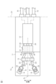
- FIG. 1 is a schematic diagram of a connector according to an embodiment.
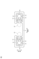
- FIG. 2 is a front view of the holder in the same embodiment.
- the connector of the present disclosure comprises: [1] An electric connector comprising: a case; a pair of electric wires arranged in the case; a pair of terminals respectively provided at the tips of the pair of electric wires; a pair of bus bars provided in the case to which the pair of terminals are respectively connected; and a pair of wire holding portions provided in the case, respectively holding the pair of electric wires, wherein each of the wire holding portions is configured to allow the electric wires to be inserted along a radial direction of the electric wires.
- each electric wire can be inserted radially into each electric wire holding portion, it is possible to connect each electric wire to each bus bar and then hold each electric wire in each electric wire holding portion.
- the wire holding portion does not narrow the range of movement of the electric wire, improving assembly workability, and after connecting the terminal to the bus bar, the wire holding portions can maintain the spacing between the pair of electric wires. Therefore, it is possible to improve assembly workability while suppressing interference between the pair of electric wires.
- the connector may include a holder that is configured as a separate entity from the case, the holder may be disposed within the case, and each of the electric wire holding portions may be formed on the holder.
- each of the wire holding portions may have a pair of opposing portions opposing each other and a pair of elastic pieces extending respectively from the pair of opposing portions, and each of the wire holding portions may be configured to hold the wires by the pair of elastic pieces.
- the pair of elastic pieces can hold the electric wire so that it does not come off from the electric wire holding portion.
- the connector 10 of this embodiment shown in FIG. 1 is a connector that is attached to an electrical device D1 mounted on a vehicle.
- the electrical device D1 include a power supply unit that is mounted on a hybrid vehicle or an electric vehicle and that integrates a battery and a high-voltage device.
- the connector 10 has a case 11, at least a portion of which is inserted inside the housing of the electrical device D1.
- the case 11 has, for example, a long shape in the direction of insertion into the electrical device D1.
- the connector 10 includes, for example, a case 11, a distribution section 12, a connector section 13, a pair of bus bars 14, a holder 15, and a number of external connection wires 16 extending from the case 11 to the outside.
- the distribution section 12, the connector section 13, the pair of bus bars 14, and the holder 15 are each housed in the case 11.
- the connector section 13 is connected to the distribution section 12 within the case 11.
- Each of the external connection wires 16 extends from the case 11 to the outside.
- the connector portion 13 includes a connection member 21 , a pair of electric wires 22 extending from the connection member 21 , and terminals 23 provided at the ends of the pair of electric wires 22 .
- connection member 21 has a pair of connection terminals 24.
- the pair of connection terminals 24 are electrically connected to the pair of electric wires 22, respectively.
- the connection member 21 is housed in the case 11.
- the connection member 21 is also configured to be detachable from the case 11. When the connection member 21 is attached to the case 11, the pair of connection terminals 24 are electrically connected to the distribution section 12.
- the distribution unit 12 is electrically connected to a plurality of external connection wires 16. Although three external connection wires 16 are shown in FIG. 1, the number of external connection wires 16 is not limited to three, and may be two, four or more. Each external connection wire 16 is drawn out to the outside of the case 11 and to the outside of the housing of the electrical device D1. The external connection wires 16 are then electrically connected to a plurality of auxiliary devices (not shown) mounted on the vehicle.
- the pair of electric wires 22 are each drawn out from a pair of outlets 25 in the connection member 21.
- the pair of outlets 25 are arranged side by side in the width direction of the connector 10.
- the width direction of the connector 10 may be simply referred to as the "width direction”.
- Each of the pair of electric wires 22 is a thick electric wire, for example, with a conductor cross-sectional area of 10 square millimeters or more, capable of handling large currents.
- Each outlet 25 of the connection member 21 is located within the case 11. Furthermore, each electric wire 22 drawn out from each outlet 25 is housed within the case 11.
- the terminals 23 provided at the ends of the pair of electric wires 22 are respectively connected to a pair of bus bars 14 held within the case 11.
- Each bus bar 14 is formed of a conductor such as metal.
- Each terminal 23 is fastened to each bus bar 14 within the case 11, for example by a bolt B. This electrically connects the terminals 23 and the bus bars 14.
- Each bus bar 14 is connected to an equipment side terminal (not shown) of the electrical device D1. This electrically connects the connector 10 and the electrical device D1.
- connection points between each terminal 23 and each bus bar 14 are set at positions on the widthwise outer side of each outlet 25.
- the distance from the center line CL of the connector 10 in the widthwise direction to the connection points between the bus bar 14 and the terminals 23 is set to be greater than the distance from the center line CL to the outlet 25.
- the holder 15 holds each of the pair of electric wires 22 so as to maintain the spacing between the pair of electric wires 22.
- the holder 15 includes, for example, a base 31 extending along the width direction, and a pair of electric wire holding portions 32 provided on the base 31.
- Each of the pair of electric wire holding portions 32 is, for example, a metal member held by a synthetic resin portion forming at least a part of the base 31.
- Each electric wire holding portion 32 has a pair of opposing portions 33 that face each other in the height direction of the connector 10, and a connecting portion 34 that connects the pair of opposing portions 33.
- the pair of opposing portions 33 extend, for example, in the width direction from both ends of the connecting portion 34 in the height direction.
- the electric wire holding portion 32 has a pair of elastic pieces 35 that extend from each tip of the pair of opposing portions 33.
- the pair of elastic pieces 35 are inclined so as to approach each other toward their tips.
- the electric wire 22 is inserted between the elastic pieces 35 of the electric wire holding portion 32 along its own diameter (see the arrows in Figure 2). At this time, each elastic piece 35 is pushed by the electric wire 22 and deforms so that the spacing between the elastic pieces 35 increases. Then, when the electric wire 22 passes over each elastic piece 35 and penetrates deep into the electric wire holding portion 32, each elastic piece 35 elastically returns to its original shape, thereby maintaining the electric wire 22 positioned between the pair of opposing portions 33. This prevents the electric wire 22 from coming off the electric wire holding portion 32.
- connection member 21 of the connector portion 13 is assembled to the case 11 , and each connection terminal portion 24 of the connection member 21 is connected to the distribution portion 12 .
- each electric wire 22 is not held by each electric wire holding portion 32 of the holder 15 (see the two-dot chain line in Figure 2). This makes it easy to handle each electric wire 22 without narrowing the range of motion of each electric wire 22, and makes it possible to easily connect each terminal 23 to each bus bar 14.
- each electric wire 22 is held in each electric wire holding portion 32 of the holder 15. At this time, as described above, each electric wire 22 is inserted into each electric wire holding portion 32 along its own radial direction. As a result, each electric wire 22 is held by each electric wire holding portion 32. Therefore, the spacing between each electric wire 22 is maintained by each electric wire holding portion 32.
- the connector 10 is provided in the case 11 and includes a pair of electric wire holding portions 32 that respectively hold a pair of electric wires 22.
- Each electric wire holding portion 32 is configured so that the electric wires 22 can be inserted along the radial direction of the electric wires 22. According to this configuration, since each electric wire 22 can be inserted along the radial direction into each electric wire holding portion 32, it is possible to hold each electric wire 22 in each electric wire holding portion 32 after connecting each electric wire 22 to each bus bar 14. As a result, the wire holding portion 32 does not narrow the movable range of the electric wires 22, and after connecting the terminal 23 to the bus bar 14, the wire holding portion 32 can hold the space between the pair of electric wires 22.
- the electric wires 22 in this embodiment are thick electric wires that are difficult to bend, the effect of this configuration, which does not narrow the movable range of the electric wires 22 when connecting the terminal 23 to the bus bar 14, is more remarkable.
- the connector 10 includes a holder 15 that is configured as a separate body from the case 11.
- the holder 15 is disposed within the case 11.
- Each electric wire holding portion 32 is formed in the holder 15. With this configuration, it is possible to assemble the holder 15 to each electric wire 22 after connecting the terminals 23 to the bus bar 14. This contributes to improving the ease of assembly.
- Each electric wire holding portion 32 has a pair of opposing portions 33 that face each other, and a pair of elastic pieces 35 that extend from each of the pair of opposing portions 33.
- Each electric wire holding portion 32 is configured to hold the electric wire 22 with the pair of elastic pieces 35. With this configuration, the pair of elastic pieces 35 can hold the electric wire 22 so that it does not come off the electric wire holding portion 32.
- the configuration of the electric wire holding portion 32 is not limited to the above embodiment, and can be changed as appropriate depending on the configuration of the connector 10 .
- the pair of opposing portions 33 of the electric wire holding portion 32 face each other in the height direction of the connector 10. That is, the electric wire holding portion 32 is configured so that the electric wire 22 can be inserted between the pair of opposing portions 33 along the width direction of the connector 10.
- the pair of opposing portions 33 may be configured so as to face each other in the width direction of the connector 10, and the electric wire 22 may be configured so that it can be inserted between the pair of opposing portions 33 along the height direction of the connector 10.
- Each electric wire holding portion 32 may be provided integrally with the case 11 .
- the number of electric wires 22 arranged in the case 11 and the number of electric wire holding portions 32 that hold the electric wires 22 are not limited to those in the above embodiment, and may be three or more.
- the electrical device D1 to which the connector 10 is connected is not limited to a power supply unit, and may be an electrical device other than a power supply unit.
- the holder 15 of the non-limiting embodiment shown in Fig. 2 is an example of a wire separation spacer configured to separate adjacent electric wires 22 in the case 11 with a predetermined separation distance range in the radial direction of the electric wires 22.
- This predetermined separation distance range of the electric wires 22 can be defined by a minimum separation distance and a maximum separation distance that is greater than the minimum separation distance by a play distance.
- the play distance which is the difference between the minimum separation distance and the maximum separation distance, may be smaller than the thickness of the electric wires 22.
- the holder 15 may be configured to allow the terminals 23 and the electric wires 22 to move in the longitudinal direction, allow the terminals 23 and the electric wires 22 to move with play in the radial direction of the electric wires 22, and prevent adjacent electric wires 22 from approaching each other closer than the minimum separation distance in the radial direction of the electric wires 22 before the terminals 23 are fastened to the bus bar 14 by the bolts B and when the electric wires 22 are held by the holder 15.
- the holder 15 may be configured such that, after the terminals 23 are fastened to the bus bar 14 by the bolts B and when the electric wires 22 are held in the holder 15, the terminals 23 and the electric wires 22 are not substantially allowed to move in the longitudinal direction of the electric wires 22, the terminals 23 are not substantially allowed to move in the radial direction of the electric wires 22, the electric wires 22 are allowed to move in the radial direction with play, and adjacent electric wires 22 are prevented from approaching each other closer than a minimum separation distance in the radial direction of the electric wires 22.
- each electric wire holding portion 32 is an example of a loose electric wire gripper configured to grip the corresponding electric wire 22 with play.
- each of the two elastic pieces 35 of each electric wire holding portion 32 may be folded inward from the corresponding opposing portion 33 via the folded portion, for example, so as to face the radially inward surface of the connecting portion 34, and the tip of each elastic piece 35 may define an electric wire entrance, which is a slit, between them.
- both elastic pieces 35 are an example of a one-way stopper configured to allow the electric wire 22 to be inserted radially from the outside of the electric wire holding portion 32 to the inside of the electric wire holding portion 32 and to prevent the electric wire 22 from being removed radially from the inside of the electric wire holding portion 32 to the outside of the electric wire holding portion 32.
Landscapes
- Details Of Connecting Devices For Male And Female Coupling (AREA)
Abstract
コネクタ(10)は、ケース(11)と、ケース(11)内に配置される一対の電線(22)と、一対の電線(22)の先端部にそれぞれ設けられる一対の端子(23)と、ケース(11)内に設けられ、一対の端子(23)がそれぞれ接続される一対のバスバー(14)と、ケース(11)内に設けられ、一対の電線(22)をそれぞれ保持する一対の電線保持部(32)と、を備える。各電線保持部(32)は、電線(22)が電線(22)の径方向に沿って挿入可能に構成されている。
Description
本開示は、コネクタに関するものである。
例えば、特許文献1には、電気機器に取り付けられるコネクタが記載されている。同コネクタは、一対の電線と電気部品とを内部に含むケースを備える。ケースが電気機器の筐体に差し込まれることで、電気機器の内部の接点とコネクタとが電気的に接続されるようになっている。
上記のようなコネクタでは、一対の電線がケース内に配置されることから、各電線の長さが短くなる傾向がある。各電線の長さが短いと、ケース内における電線の取り回しが難しくなる。その結果、組付作業性が悪化するおそれがある。
さらに、上記のようなコネクタでは、一対の電線同士の干渉を抑制するために、各電線を保持するホルダをケース内に設ける場合がある。この場合、ホルダによって一対の電線の間の間隔が保持されるため、一対の電線同士の干渉を抑えることが可能となる。しかしながら、各電線をホルダで保持する構成では、各電線の可動域を狭めてしまうため、電線の短さも相まってさらに組付作業性が悪化するおそれがある。
本開示の目的は、一対の電線同士の干渉を抑えつつも、組付作業性の向上を可能としたコネクタを提供することにある。
本開示のコネクタは、ケースと、前記ケース内に配置される一対の電線と、前記一対の電線の先端部にそれぞれ設けられる一対の端子と、前記ケース内に設けられ、前記一対の端子がそれぞれ接続される一対のバスバーと、前記ケース内に設けられ、前記一対の電線をそれぞれ保持する一対の電線保持部と、を備え、前記各電線保持部は、前記電線が前記電線の径方向に沿って挿入可能に構成されている。
本開示のコネクタによれば、一対の電線同士の干渉を抑えつつも、組付作業性を向上させることが可能となる。
[本開示の実施形態の説明]
最初に本開示の実施態様を列記して説明する。
本開示のコネクタは、
[1]ケースと、前記ケース内に配置される一対の電線と、前記一対の電線の先端部にそれぞれ設けられる一対の端子と、前記ケース内に設けられ、前記一対の端子がそれぞれ接続される一対のバスバーと、前記ケース内に設けられ、前記一対の電線をそれぞれ保持する一対の電線保持部と、を備え、前記各電線保持部は、前記電線が前記電線の径方向に沿って挿入可能に構成されている。
最初に本開示の実施態様を列記して説明する。
本開示のコネクタは、
[1]ケースと、前記ケース内に配置される一対の電線と、前記一対の電線の先端部にそれぞれ設けられる一対の端子と、前記ケース内に設けられ、前記一対の端子がそれぞれ接続される一対のバスバーと、前記ケース内に設けられ、前記一対の電線をそれぞれ保持する一対の電線保持部と、を備え、前記各電線保持部は、前記電線が前記電線の径方向に沿って挿入可能に構成されている。
この構成によれば、各電線保持部に対して、各電線を径方向に沿って挿入可能であるため、各電線を各バスバーに接続した後に、各電線を各電線保持部に保持させることが可能となる。これにより、端子をバスバーに接続する際には、電線保持部によって電線の可動域を狭めることなく、組付作業性を良いものとしつつ、端子をバスバーに接続した後においては、各電線保持部によって一対の電線の間の間隔を保持できる。したがって、一対の電線同士の干渉を抑えつつも、組付作業性を向上させることが可能となる。
[2]上記[1]において、前記コネクタは、前記ケースに対して別体として構成されるホルダを備え、前記ホルダは、前記ケース内に配置され、前記各電線保持部は、前記ホルダに形成されていてもよい。
この構成によれば、端子をバスバーに接続した後に、ホルダを各電線に対して組み付けることが可能となる。これにより、組付作業性の向上に寄与できる。
[3]上記[1]または[2]において、前記各電線保持部は、互いに対向する一対の対向部と、前記一対の対向部からそれぞれ延出する一対の弾性片と、を有し、前記各電線保持部は、前記一対の弾性片によって前記電線を保持する構成であってもよい。
[3]上記[1]または[2]において、前記各電線保持部は、互いに対向する一対の対向部と、前記一対の対向部からそれぞれ延出する一対の弾性片と、を有し、前記各電線保持部は、前記一対の弾性片によって前記電線を保持する構成であってもよい。
この構成によれば、一対の弾性片によって、電線が電線保持部から外れないように保持することが可能となる。
[本開示の実施形態の詳細]
本開示のコネクタの具体例を、以下に図面を参照しつつ説明する。各図面では、説明の便宜上、構成の一部を誇張または簡略化して示す場合がある。また、各部分の寸法比率については各図面で異なる場合がある。
[本開示の実施形態の詳細]
本開示のコネクタの具体例を、以下に図面を参照しつつ説明する。各図面では、説明の便宜上、構成の一部を誇張または簡略化して示す場合がある。また、各部分の寸法比率については各図面で異なる場合がある。
図1に示す本実施形態のコネクタ10は、車両に搭載された電気機器D1に取り付けられるコネクタである。電気機器D1としては、例えばハイブリッド自動車や電気自動車に搭載され、バッテリと高圧デバイスとが一体化された電源ユニット等が挙げられる。コネクタ10は、電気機器D1の筐体内部に少なくとも一部が挿入されるケース11を有する。ケース11は、例えば、電気機器D1への挿入方向において長い形状を有している。
コネクタ10は、例えば、ケース11と、分配部12と、コネクタ部13と、一対のバスバー14と、ホルダ15と、ケース11から外部に延びる複数の外部接続電線16と、を備える。分配部12、コネクタ部13、一対のバスバー14およびホルダ15の各々は、ケース11に収容されている。コネクタ部13は、ケース11内において分配部12に接続されている。各外部接続電線16は、ケース11から外部に延びている。
(ケース11の内部の構成)
コネクタ部13は、接続部材21と、接続部材21から延びる一対の電線22と、一対の電線22の先端部にそれぞれ設けられた端子23と、を備える。
コネクタ部13は、接続部材21と、接続部材21から延びる一対の電線22と、一対の電線22の先端部にそれぞれ設けられた端子23と、を備える。
接続部材21は、一対の接続端子部24を有する。一対の接続端子部24は、一対の電線22にそれぞれに電気的に接続されている。接続部材21は、ケース11内に収容されている。また、接続部材21は、ケース11に対して着脱可能に構成されている。接続部材21がケース11に取り付けられた状態において、一対の接続端子部24は、分配部12に電気的に接続される。
分配部12は、複数の外部接続電線16にそれぞれ電気的に接続されている。図1では、複数の外部接続電線16を3つ図示しているが、外部接続電線16の数は3つに限らず、2つ、または4つ以上であってもよい。各外部接続電線16は、ケース11の外部および電気機器D1の筐体の外部に引き出される。そして、複数の外部接続電線16は、車両に搭載される図示しない複数の補機にそれぞれ電気的に接続される。
一対の電線22は、接続部材21における一対の引き出し口25からそれぞれ引き出されている。一対の引き出し口25は、コネクタ10の幅方向に並んで設けられている。なお、以下の説明では、コネクタ10の幅方向について、単に「幅方向」と称する場合がある。一対の電線22の各々は、例えば、大電流に対応した、導体断面積が10平方ミリメートル以上の太物電線である。接続部材21の各引き出し口25は、ケース11内に位置している。また、各引き出し口25から引き出される各電線22は、ケース11内に収容されている。
一対の電線22の先端部にそれぞれ設けられた端子23は、ケース11内に保持された一対のバスバー14にそれぞれ接続されている。各バスバー14は、金属等の導体にて形成されている。各端子23は、ケース11内において、例えばボルトBによって各バスバー14に締結固定されている。これにより、端子23とバスバー14とが電気的に接続される。各バスバー14は、電気機器D1が有する図示しない機器側端子と接続される。これにより、コネクタ10と電気機器D1とが電気的に接続される。
各端子23と各バスバー14との接続部位は、各引き出し口25よりも幅方向外側の位置に設定されている。すなわち、コネクタ10の幅方向の中心線CLからの距離は、中心線CLから引き出し口25までの距離よりも、中心線CLからバスバー14と端子23との接続部分までの距離の方がより大きく設定されている。これにより、端子23をバスバー14に接続する際には、端子23を引き出し口25に対して幅方向の外側に移動させつつバスバー14に接続させる必要がある。このため、電線22の取り回しを容易にして端子23をバスバー14に接続しやすくするために、電線22には余長が設定されている。
(ホルダ15の構成)
図2に示すように、ホルダ15は、一対の電線22の間の間隔を保持するように各電線22を保持する。ホルダ15は、例えば、幅方向に沿って延在する基部31と、基部31に設けられた一対の電線保持部32と、を備える。一対の電線保持部32の各々は、例えば、基部31の少なくとも一部を形成する合成樹脂部分に保持された金属製の部材である。
図2に示すように、ホルダ15は、一対の電線22の間の間隔を保持するように各電線22を保持する。ホルダ15は、例えば、幅方向に沿って延在する基部31と、基部31に設けられた一対の電線保持部32と、を備える。一対の電線保持部32の各々は、例えば、基部31の少なくとも一部を形成する合成樹脂部分に保持された金属製の部材である。
各電線保持部32は、コネクタ10の高さ方向に対向する一対の対向部33と、一対の対向部33同士を繋ぐ連結部34とを有する。一対の対向部33は、例えば、連結部34の高さ方向の両端部から幅方向に沿って延出している。電線保持部32は、一対の対向部33の各先端部から延出する一対の弾性片35を有している。一対の弾性片35は、自身の先端に向かって互いに近づくように傾斜している。
電線22は、電線保持部32の各弾性片35の間に、自身の径方向に沿って挿入される(図2中の矢印を参照)。このとき、各弾性片35は、電線22に押されて各弾性片35の間隔が広がるように変形する。そして、電線22が各弾性片35を越えて電線保持部32の奥まで入り込むと、各弾性片35は、弾性復帰することにより、電線22が一対の対向部33の間に位置する状態を保持する。これにより、電線22が電線保持部32から外れないようになっている。
(コネクタ10の組付態様)
次に、コネクタ10の組付態様について説明する。
まず、コネクタ部13の接続部材21をケース11に組み付けることで、接続部材21の各接続端子部24を分配部12に接続する。
次に、コネクタ10の組付態様について説明する。
まず、コネクタ部13の接続部材21をケース11に組み付けることで、接続部材21の各接続端子部24を分配部12に接続する。
次に、接続部材21の各引き出し口25から延びる各電線22の先端部に設けられた各端子23を、バスバー14に締結固定する。このとき、各電線22は、ホルダ15の各電線保持部32に保持させていない状態とする(図2における2点鎖線を参照)。これにより、各電線22の可動域が狭められることなく、各電線22の取り回しが容易となるため、各端子23を各バスバー14に容易に接続させることが可能となる。
各端子23を各バスバー14に接続した後、各電線22をホルダ15の各電線保持部32に保持させる。このとき、前述のように、各電線22を自身の径方向に沿って各電線保持部32に挿入する。これにより、各電線22が各電線保持部32にて保持される。したがって、各電線保持部32によって、各電線22の間の間隔が保持される。
本実施形態の効果について説明する。
(1)コネクタ10は、ケース11内に設けられ、一対の電線22をそれぞれ保持する一対の電線保持部32を備える。各電線保持部32は、電線22が電線22の径方向に沿って挿入可能に構成されている。この構成によれば、各電線保持部32に対して、各電線22を径方向に沿って挿入可能であるため、各電線22を各バスバー14に接続した後に、各電線22を各電線保持部32に保持させることが可能となる。これにより、電線保持部32によって電線22の可動域を狭めることなく、組付作業性を良いものとしつつ、端子23をバスバー14に接続した後においては、各電線保持部32によって一対の電線22の間の間隔を保持できる。したがって、一対の電線22同士の干渉を抑えつつも、組付作業性を向上させることが可能となる。また、本実施形態の電線22は、屈曲させにくい太物電線であるため、端子23とバスバー14の接続時に電線22の可動域を狭めない本構成の効果がより顕著となる。
(1)コネクタ10は、ケース11内に設けられ、一対の電線22をそれぞれ保持する一対の電線保持部32を備える。各電線保持部32は、電線22が電線22の径方向に沿って挿入可能に構成されている。この構成によれば、各電線保持部32に対して、各電線22を径方向に沿って挿入可能であるため、各電線22を各バスバー14に接続した後に、各電線22を各電線保持部32に保持させることが可能となる。これにより、電線保持部32によって電線22の可動域を狭めることなく、組付作業性を良いものとしつつ、端子23をバスバー14に接続した後においては、各電線保持部32によって一対の電線22の間の間隔を保持できる。したがって、一対の電線22同士の干渉を抑えつつも、組付作業性を向上させることが可能となる。また、本実施形態の電線22は、屈曲させにくい太物電線であるため、端子23とバスバー14の接続時に電線22の可動域を狭めない本構成の効果がより顕著となる。
(2)コネクタ10は、ケース11に対して別体として構成されるホルダ15を備える。ホルダ15は、ケース11内に配置されている。各電線保持部32は、ホルダ15に形成されている。この構成によれば、端子23をバスバー14に接続した後に、ホルダ15を各電線22に対して組み付けることが可能となる。これにより、組付作業性の向上に寄与できる。
(3)各電線保持部32は、互いに対向する一対の対向部33と、一対の対向部33からそれぞれ延出する一対の弾性片35と、を有する。各電線保持部32は、一対の弾性片35によって電線22を保持する構成とされる。この構成によれば、一対の弾性片35によって、電線22が電線保持部32から外れないように保持することが可能となる。
(変更例)
本実施形態は、以下のように変更して実施することができる。本実施形態及び以下の変更例は、技術的に矛盾しない範囲で互いに組み合わせて実施することができる。
本実施形態は、以下のように変更して実施することができる。本実施形態及び以下の変更例は、技術的に矛盾しない範囲で互いに組み合わせて実施することができる。
・電線保持部32の構成は上記実施形態に限定されるものではなく、コネクタ10の構成に応じて適宜変更可能である。
例えば、上記実施形態では、電線保持部32における一対の対向部33は、コネクタ10の高さ方向に対向している。すなわち、電線保持部32は、電線22をコネクタ10の幅方向に沿って一対の対向部33の間に挿入可能な構成とされている。これに対し、一対の対向部33をコネクタ10の幅方向に対向する構成として、電線22を一対の対向部33の間にコネクタ10の高さ方向に沿って挿入可能な構成としてもよい。
例えば、上記実施形態では、電線保持部32における一対の対向部33は、コネクタ10の高さ方向に対向している。すなわち、電線保持部32は、電線22をコネクタ10の幅方向に沿って一対の対向部33の間に挿入可能な構成とされている。これに対し、一対の対向部33をコネクタ10の幅方向に対向する構成として、電線22を一対の対向部33の間にコネクタ10の高さ方向に沿って挿入可能な構成としてもよい。
・各電線保持部32をケース11に一体に設けてもよい。
・ケース11内に配置される電線22の本数、および、電線22を保持する電線保持部32の個数は、上記実施形態に限定されるものではなく、それぞれ3つ以上であってもよい。
・ケース11内に配置される電線22の本数、および、電線22を保持する電線保持部32の個数は、上記実施形態に限定されるものではなく、それぞれ3つ以上であってもよい。
・コネクタ10を接続する対象となる電気機器D1は、電源ユニットに限定されることはなく、電源ユニット以外の電気機器であってもよい。
・図2に示した非限定的実施形態のホルダ15は、ケース11内で隣り合う複数の電線22を所定の分離距離範囲をもって電線22の径方向に分離させるように構成された電線分離スペーサの一例である。電線22のこの所定の分離距離範囲は、最短分離距離と、当該最短分離距離よりも遊び距離だけ大きい最長分離距離とによって画定することができる。図2に示した例のように、最短分離距離と最長分離距離との差である遊び距離は、電線22の太さよりも小さくてよい。例えば、ホルダ15は、端子23がボルトBによってバスバー14に締結固定される前でかつ電線22がホルダ15に保持されているときに、端子23および電線22が長手方向に移動するのを許容し、かつ端子23および電線22が電線22の径方向に遊びをもって移動するのを許容し、かつ隣接する電線22同士が電線22の径方向において最低分離距離よりも接近するのを妨害するように構成されてよい。ホルダ15は、端子23がボルトBによってバスバー14に締結固定された後でかつ電線22がホルダ15に保持されているときに、端子23および電線22が電線22の長手方向に移動するのを実質的に許容せず、かつ端子23が電線22の径方向に移動するのを実質的に許容せず、かつ電線22が径方向に遊びをもって移動するのを許容し、かつ隣接する電線22同士が電線22の径方向において最低分離距離よりも接近するのを妨害するように構成されてよい。
・図2に示した非限定的実施形態のホルダ15は、ケース11内で隣り合う複数の電線22を所定の分離距離範囲をもって電線22の径方向に分離させるように構成された電線分離スペーサの一例である。電線22のこの所定の分離距離範囲は、最短分離距離と、当該最短分離距離よりも遊び距離だけ大きい最長分離距離とによって画定することができる。図2に示した例のように、最短分離距離と最長分離距離との差である遊び距離は、電線22の太さよりも小さくてよい。例えば、ホルダ15は、端子23がボルトBによってバスバー14に締結固定される前でかつ電線22がホルダ15に保持されているときに、端子23および電線22が長手方向に移動するのを許容し、かつ端子23および電線22が電線22の径方向に遊びをもって移動するのを許容し、かつ隣接する電線22同士が電線22の径方向において最低分離距離よりも接近するのを妨害するように構成されてよい。ホルダ15は、端子23がボルトBによってバスバー14に締結固定された後でかつ電線22がホルダ15に保持されているときに、端子23および電線22が電線22の長手方向に移動するのを実質的に許容せず、かつ端子23が電線22の径方向に移動するのを実質的に許容せず、かつ電線22が径方向に遊びをもって移動するのを許容し、かつ隣接する電線22同士が電線22の径方向において最低分離距離よりも接近するのを妨害するように構成されてよい。
・図2に示した非限定的実施形態において、各電線保持部32は、対応する電線22を、遊びをもって把持するように構成された緩い電線グリッパーの一例である。例えば、各電線保持部32の2つの弾性片35の各々は、折り返し部を介して対応する対向部33から内向きに、例えば連結部34の径方向内向き面を指向するように、折り返されてよい、各弾性片35の先端は、スリットである電線入口をそれらの間に画定してよい。電線保持部32が自然形状であるときに、すなわち両弾性片35がいずれも弾性変形していないときに、両弾性片35は、電線保持部32の外部から電線保持部32の内部への電線22の径方向挿入を許容しかつ電線保持部32の内部から電線保持部32の外部への電線22の径方向取り外しを妨害するように構成された、ワンウェイストッパの一例である。
・今回開示された実施形態及び変更例はすべての点で例示であって、本発明はこれらの例示に限定されるものではない。すなわち、本発明の範囲は、特許請求の範囲によって示され、特許請求の範囲と均等の意味及び範囲内でのすべての変更が含まれることが意図される。
10 コネクタ
11 ケース
12 分配部
13 コネクタ部
14 バスバー
15 ホルダ
16 外部接続電線
21 接続部材
22 電線
23 端子
24 接続端子部
25 引き出し口
31 基部
32 電線保持部
33 対向部
34 連結部
35 弾性片
B ボルト
CL 中心線
D1 電気機器
11 ケース
12 分配部
13 コネクタ部
14 バスバー
15 ホルダ
16 外部接続電線
21 接続部材
22 電線
23 端子
24 接続端子部
25 引き出し口
31 基部
32 電線保持部
33 対向部
34 連結部
35 弾性片
B ボルト
CL 中心線
D1 電気機器
Claims (3)
- ケースと、
前記ケース内に配置される一対の電線と、
前記一対の電線の先端部にそれぞれ設けられる一対の端子と、
前記ケース内に設けられ、前記一対の端子がそれぞれ接続される一対のバスバーと、
前記ケース内に設けられ、前記一対の電線をそれぞれ保持する一対の電線保持部と、
を備え、
前記各電線保持部は、前記電線が前記電線の径方向に沿って挿入可能に構成されている、
コネクタ。 - 前記ケースに対して別体として構成されるホルダを備え、
前記ホルダは、前記ケース内に配置され、
前記各電線保持部は、前記ホルダに形成されている、
請求項1に記載のコネクタ。 - 前記各電線保持部は、互いに対向する一対の対向部と、前記一対の対向部からそれぞれ延出する一対の弾性片と、を有し、
前記各電線保持部は、前記一対の弾性片によって前記電線を保持する、
請求項1に記載のコネクタ。
Applications Claiming Priority (2)
| Application Number | Priority Date | Filing Date | Title |
|---|---|---|---|
| JP2023-098665 | 2023-06-15 | ||
| JP2023098665A JP2024179657A (ja) | 2023-06-15 | 2023-06-15 | コネクタ |
Publications (1)
| Publication Number | Publication Date |
|---|---|
| WO2024257588A1 true WO2024257588A1 (ja) | 2024-12-19 |
Family
ID=93851784
Family Applications (1)
| Application Number | Title | Priority Date | Filing Date |
|---|---|---|---|
| PCT/JP2024/019329 Ceased WO2024257588A1 (ja) | 2023-06-15 | 2024-05-27 | コネクタ |
Country Status (2)
| Country | Link |
|---|---|
| JP (1) | JP2024179657A (ja) |
| WO (1) | WO2024257588A1 (ja) |
Citations (6)
| Publication number | Priority date | Publication date | Assignee | Title |
|---|---|---|---|---|
| JPH10189147A (ja) * | 1996-12-24 | 1998-07-21 | Yazaki Corp | シールドコネクタ |
| JP2003092821A (ja) * | 2001-07-10 | 2003-03-28 | Yazaki Corp | 長尺物品の保持構造 |
| JP2011072164A (ja) * | 2009-09-28 | 2011-04-07 | Fujitsu Frontech Ltd | ケーブル保持機構 |
| WO2017198985A1 (en) * | 2016-05-18 | 2017-11-23 | Electro Expo Limited | Cable grip for housing system for electrical connectors |
| JP2021125334A (ja) * | 2020-02-04 | 2021-08-30 | 住友電装株式会社 | ワイヤハーネス |
| JP2021175223A (ja) * | 2020-04-21 | 2021-11-01 | 株式会社オートネットワーク技術研究所 | 車載電気部品内回路ユニット |
-
2023
- 2023-06-15 JP JP2023098665A patent/JP2024179657A/ja active Pending
-
2024
- 2024-05-27 WO PCT/JP2024/019329 patent/WO2024257588A1/ja not_active Ceased
Patent Citations (6)
| Publication number | Priority date | Publication date | Assignee | Title |
|---|---|---|---|---|
| JPH10189147A (ja) * | 1996-12-24 | 1998-07-21 | Yazaki Corp | シールドコネクタ |
| JP2003092821A (ja) * | 2001-07-10 | 2003-03-28 | Yazaki Corp | 長尺物品の保持構造 |
| JP2011072164A (ja) * | 2009-09-28 | 2011-04-07 | Fujitsu Frontech Ltd | ケーブル保持機構 |
| WO2017198985A1 (en) * | 2016-05-18 | 2017-11-23 | Electro Expo Limited | Cable grip for housing system for electrical connectors |
| JP2021125334A (ja) * | 2020-02-04 | 2021-08-30 | 住友電装株式会社 | ワイヤハーネス |
| JP2021175223A (ja) * | 2020-04-21 | 2021-11-01 | 株式会社オートネットワーク技術研究所 | 車載電気部品内回路ユニット |
Also Published As
| Publication number | Publication date |
|---|---|
| JP2024179657A (ja) | 2024-12-26 |
Similar Documents
| Publication | Publication Date | Title |
|---|---|---|
| JP5848963B2 (ja) | シールド構造及びワイヤハーネス | |
| US10804656B2 (en) | Connector connectable to different cable types, and cable harness including the connector | |
| CN104885305B (zh) | 电力端子连接器 | |
| JP5779010B2 (ja) | バスバモジュール構造体 | |
| JP2019129007A (ja) | 導電路及びワイヤハーネス | |
| KR102098404B1 (ko) | 자동차용 고전압 커넥터 | |
| KR102338051B1 (ko) | 동축 커넥터 및 동축 케이블을 구비한 동축 커넥터 | |
| WO2015098836A1 (ja) | ワイヤハーネス及びワイヤハーネスの導電路挿通方法 | |
| EP2867914B1 (en) | Fuse apparatus and manufacturing method thereof | |
| US11804677B2 (en) | Electrical terminal module and connector with improved shielding features | |
| JP7205406B2 (ja) | 接続モジュール | |
| US9889805B2 (en) | Wire harness and wire harness manufacturing method | |
| JP2024179657A (ja) | コネクタ | |
| WO2018080880A1 (en) | Connector | |
| JP2024132420A (ja) | ワイヤハーネス、及びプロテクタ | |
| US20180358796A1 (en) | Cable extra length absorbing structure and bus bar module | |
| JP2024132421A (ja) | ワイヤハーネス、及びプロテクタ | |
| KR102812112B1 (ko) | 고전압 커넥터 | |
| US20170167640A1 (en) | Corrugated tube and wire harness | |
| KR102764461B1 (ko) | 자동차용 커넥터 | |
| CN209675560U (zh) | 一种高稳定性接插件 | |
| JP2007227257A (ja) | ワイヤハーネス及びその製造方法 | |
| JP7518106B2 (ja) | 端子接続構造、およびコネクタ | |
| JP6594128B2 (ja) | ワイヤハーネス | |
| JP7491894B2 (ja) | 配索構造 |
Legal Events
| Date | Code | Title | Description |
|---|---|---|---|
| 121 | Ep: the epo has been informed by wipo that ep was designated in this application |
Ref document number: 24821248 Country of ref document: EP Kind code of ref document: A1 |
|
| NENP | Non-entry into the national phase |
Ref country code: DE |
|
| 122 | Ep: pct application non-entry in european phase |
Ref document number: 24821248 Country of ref document: EP Kind code of ref document: A1 |