WO2024257579A1 - 電流センサ - Google Patents
電流センサ Download PDFInfo
- Publication number
- WO2024257579A1 WO2024257579A1 PCT/JP2024/019065 JP2024019065W WO2024257579A1 WO 2024257579 A1 WO2024257579 A1 WO 2024257579A1 JP 2024019065 W JP2024019065 W JP 2024019065W WO 2024257579 A1 WO2024257579 A1 WO 2024257579A1
- Authority
- WO
- WIPO (PCT)
- Prior art keywords
- bus bar
- detection element
- magnetic detection
- sensor unit
- current
- Prior art date
- Legal status (The legal status is an assumption and is not a legal conclusion. Google has not performed a legal analysis and makes no representation as to the accuracy of the status listed.)
- Pending
Links
Images


Classifications
-
- G—PHYSICS
- G01—MEASURING; TESTING
- G01R—MEASURING ELECTRIC VARIABLES; MEASURING MAGNETIC VARIABLES
- G01R15/00—Details of measuring arrangements of the types provided for in groups G01R17/00 - G01R29/00, G01R33/00 - G01R33/26 or G01R35/00
- G01R15/14—Adaptations providing voltage or current isolation, e.g. for high-voltage or high-current networks
- G01R15/20—Adaptations providing voltage or current isolation, e.g. for high-voltage or high-current networks using galvano-magnetic devices, e.g. Hall-effect devices, i.e. measuring a magnetic field via the interaction between a current and a magnetic field, e.g. magneto resistive or Hall effect devices
-
- G—PHYSICS
- G01—MEASURING; TESTING
- G01R—MEASURING ELECTRIC VARIABLES; MEASURING MAGNETIC VARIABLES
- G01R17/00—Measuring arrangements involving comparison with a reference value, e.g. bridge
- G01R17/10—AC or DC measuring bridges
- G01R17/12—AC or DC measuring bridges using comparison of currents, e.g. bridges with differential current output
-
- G—PHYSICS
- G01—MEASURING; TESTING
- G01R—MEASURING ELECTRIC VARIABLES; MEASURING MAGNETIC VARIABLES
- G01R33/00—Arrangements or instruments for measuring magnetic variables
- G01R33/02—Measuring direction or magnitude of magnetic fields or magnetic flux
- G01R33/06—Measuring direction or magnitude of magnetic fields or magnetic flux using galvano-magnetic devices
- G01R33/07—Hall effect devices
-
- G—PHYSICS
- G01—MEASURING; TESTING
- G01R—MEASURING ELECTRIC VARIABLES; MEASURING MAGNETIC VARIABLES
- G01R33/00—Arrangements or instruments for measuring magnetic variables
- G01R33/02—Measuring direction or magnitude of magnetic fields or magnetic flux
- G01R33/06—Measuring direction or magnitude of magnetic fields or magnetic flux using galvano-magnetic devices
- G01R33/09—Magnetoresistive devices
Definitions
- the present invention relates to a current sensor.
- Patent Document 1 is a prior art document that discloses the configuration of a current measuring device.
- the current measuring device described in Patent Document 1 measures the current value of each of three conductors through which currents whose sum total is zero flow.
- the current measuring device includes first and second coreless current sensors, a holding means, a calculating means, and a shielding member.
- the first and second coreless current sensors are disposed at predetermined relative positions with respect to the three conductors.
- the holding means acquires and holds coefficients required for the measurement in a preparation stage before measuring the current flowing through the three conductors.
- the calculating means utilizes the fact that the sum total of the current values flowing through the three conductors is zero to calculate the current value flowing through each conductor based on the output signals of the first and second coreless current sensors and the coefficients held in the holding means.
- the shielding member surrounds each conductor and the first and second coreless current sensors.
- a shielding member is provided, which increases the size of the device and reduces the accuracy of current measurement due to the influence of the shielding member.
- the device requires complex calculations because the current value of each conductor is calculated based on previously acquired parameters. This lengthens the time required to calculate the current value, which reduces the responsiveness of the current measurement.
- the present invention was made in consideration of the above problems, and aims to provide a current sensor that can improve measurement accuracy and responsiveness while reducing the overall size.
- the current sensor includes a first bus bar, a second bus bar, and a third bus bar, a first sensor unit, a second sensor unit, and a calculation unit.
- the first bus bar, the second bus bar, and the third bus bar each extend in a first direction while being spaced apart from one another, and are arranged in a second direction perpendicular to the first direction, and a three-phase AC current flows through them.
- the first sensor unit is disposed between two bus bars other than any one of the first bus bar, the second bus bar, and the third bus bar that is the object of measurement.
- the second sensor unit measures one of the two bus bars other than the one object of measurement, and is disposed between the one object of measurement and the other of the two bus bars other than the one object of measurement.
- the calculation unit calculates the current value of each of the first bus bar, the second bus bar, and the third bus bar from the output values of each of the first sensor unit and the second sensor unit.
- the first sensor unit includes a first magnetic detection element and a second magnetic detection element.
- the first magnetic detection element and the second magnetic detection element each have a sensitivity axis facing a third direction perpendicular to the first direction and the second direction, are aligned in the second direction, and detect a magnetic field generated by a current flowing through the first bus bar, the second bus bar, and the third bus bar.
- the second sensor unit includes a third magnetic detection element and a fourth magnetic detection element.
- the third magnetic detection element and the fourth magnetic detection element each have a sensitivity axis facing the third direction, are aligned in the second direction, and detect a magnetic field generated by a current flowing through the first bus bar, the second bus bar, and the third bus bar.
- the distance between the first magnetic detection element and one of the two bus bars other than the one bus bar to be measured, and the distance between the second magnetic detection element and the other of the two bus bars other than the one bus bar to be measured are approximately equal.
- the distance between the third magnetic detection element and the other of the two bus bars other than the one bus bar to be measured, and the distance between the fourth magnetic detection element and the one bus bar to be measured are approximately equal.
- the calculation unit can calculate the current value flowing through the one bus bar to be measured based on the differential output value between the measurement value of the first magnetic detection element and the measurement value of the second magnetic detection element in the first sensor unit, can calculate the current value flowing through one of the two bus bars other than the one bus bar to be measured based on the differential output value between the measurement value of the third magnetic detection element and the measurement value of the fourth magnetic detection element in the second sensor unit, and can calculate the current value flowing through the other of the two bus bars other than the one bus bar to be measured by adding the current value flowing through the one bus bar to the current value flowing through one of the two bus bars other than the one bus bar to be measured.
- the present invention makes it possible to reduce the overall size of the current sensor while improving measurement accuracy and responsiveness.
- FIG. 1 is a perspective view showing a configuration of a current sensor according to a first embodiment of the present invention
- 1 is a cross-sectional view showing a configuration of a current sensor according to a first embodiment of the present invention.
- 2 is a block diagram showing electrical connections of each component in the current sensor according to the first embodiment of the present invention.
- FIG. 4 is a cross-sectional view showing a state in which a magnetic field generated from each bus bar in the current sensor according to the first embodiment of the present invention is detected by a first magnetic detection element of a first sensor unit.
- FIG. 4 is a cross-sectional view showing a state in which a magnetic field generated from each bus bar in the current sensor according to the first embodiment of the present invention is detected by a second magnetic detection element of the first sensor unit.
- FIG. 1 is a circuit diagram illustrating a schematic circuit configuration of a current sensor according to a first embodiment of the present invention.
- 6 is a cross-sectional view showing a configuration of a current sensor according to
- the direction in which the bus bars are lined up is the X direction as the second direction
- the direction in which the bus bars extend is the Y direction as the first direction
- the direction along the sensitivity axis of each magnetic detection element is the Z direction as the third direction.
- the distance between each component in the current sensor is the distance connecting the centers of each component.
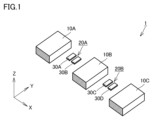
- Fig. 1 is a perspective view showing a configuration of a current sensor according to a first embodiment of the present invention.
- Fig. 2 is a cross-sectional view showing a configuration of a current sensor according to a first embodiment of the present invention.
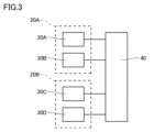
- Fig. 3 is a block diagram showing electrical connections of each component in the current sensor according to the first embodiment of the present invention.
- the current sensor 1 includes a first bus bar 10A, a second bus bar 10B, a third bus bar 10C, a first sensor unit 20A, a second sensor unit 20B, and a calculation unit 40.
- the first bus bar 10A, the second bus bar 10B, and the third bus bar 10C are three-phase, three-wire bus bars. Three-phase AC current flows through each of the first bus bar 10A, the second bus bar 10B, and the third bus bar 10C. The currents flowing through each of the first bus bar 10A, the second bus bar 10B, and the third bus bar 10C constitute AC currents that are equal in amplitude and shifted in phase by 120° from each other.
- the first current may be a U-phase AC current
- the second current may be a V-phase AC current
- the third current may be a W-phase AC current.
- the first bus bar 10A, the second bus bar 10B, and the third bus bar 10C are arranged at intervals in a second direction (X direction) perpendicular to the first direction (Y direction).
- the third bus bar 10C is arranged such that the distance between the third bus bar 10C and the second bus bar 10B in the second direction (X direction) is equal to the distance between the first bus bar 10A and the second bus bar 10B. Note that the distance between the first bus bar 10A and the second bus bar 10B and the distance between the second bus bar 10B and the third bus bar 10C in the second direction (X direction) may be different.
- the first bus bar 10A extends linearly along a first direction (Y direction).
- the current value (I 1 ) of the first current flowing through the first bus bar 10A is an AC current and can be a positive value or a negative value.
- the second bus bar 10B extends linearly along the first direction (Y direction).
- the current value (I 2 ) of the second current flowing through the second bus bar 10B is an AC current and can be a positive value or a negative value.
- the third bus bar 10C extends linearly along the first direction (Y direction).
- the current value (I 3 ) of the third current flowing through the third bus bar 10C is an AC current and can be a positive value or a negative value.
- the first sensor unit 20A is disposed between any two bus bars other than the one bus bar to be measured among the first bus bar 10A, the second bus bar 10B, and the third bus bar 10C. In this embodiment, the first sensor unit 20A measures the third bus bar 10C as the one bus bar to be measured. Therefore, the first sensor unit 20A is disposed between the first bus bar 10A and the second bus bar 10B.
- the first sensor unit 20A is disposed, for example, on a substrate (not shown). The position of the first sensor unit 20A may be fixed by a resin mold or the like.
- the first sensor unit 20A includes a first magnetic detection element 30A and a second magnetic detection element 30B.
- Each of the first magnetic detection element 30A and the second magnetic detection element 30B is capable of detecting a magnetic field generated by a current flowing through the first bus bar 10A, the second bus bar 10B, and the third bus bar 10C.
- the first magnetic detection element 30A and the second magnetic detection element 30B each have a sensitivity axis oriented in a third direction (Z direction) perpendicular to the first direction (Y direction) and the second direction (X direction). Specifically, the first magnetic detection element 30A has a first sensitivity axis A1 oriented in the third direction (Z direction). The second magnetic detection element 30B has a second sensitivity axis A2 oriented in the third direction (Z direction).
- the first magnetic detection element 30A and the second magnetic detection element 30B are aligned in the second direction (X direction).
- the first magnetic detection element 30A and the second magnetic detection element 30B are aligned in the second direction (X direction) with their positions in the third direction (Z direction) being approximately the same.
- the second sensor unit 20B measures one of the two bus bars other than the one bus bar to be measured.
- the second sensor unit 20B measures the first bus bar 10A as one of the two bus bars other than the one bus bar to be measured.
- the second sensor unit 20B is disposed between the bus bar of the one measurement target and the other of the two bus bars other than the one measurement target.
- the second sensor unit 20B is disposed between the third bus bar 10C and the second bus bar 10B, which is the other of the two bus bars other than the one measurement target.
- the second sensor unit 20B is disposed, for example, on a substrate (not shown). The position of the second sensor unit 20B may be fixed by a resin mold or the like.
- the second sensor unit 20B includes a third magnetic detection element 30C and a fourth magnetic detection element 30D.
- Each of the third magnetic detection element 30C and the fourth magnetic detection element 30D is capable of detecting a magnetic field generated by a current flowing through the first bus bar 10A, the second bus bar 10B, and the third bus bar 10C.
- the third magnetic detection element 30C and the fourth magnetic detection element 30D each have a sensitivity axis oriented in the third direction (Z direction). Specifically, the third magnetic detection element 30C has a third sensitivity axis A3 oriented in the third direction (Z direction). The fourth magnetic detection element 30D has a fourth sensitivity axis A4 oriented in the third direction (Z direction).
- the third magnetic detection element 30C and the fourth magnetic detection element 30D are aligned in the second direction (X direction).
- the third magnetic detection element 30C and the fourth magnetic detection element 30D are aligned in the second direction (X direction) with their positions in the third direction (Z direction) being approximately the same.
- At least one of the first magnetic detection element 30A, the second magnetic detection element 30B, the third magnetic detection element 30C, and the fourth magnetic detection element 30D in the first sensor unit 20A and the second sensor unit 20B may have a circuit consisting of at least two or more magnetic resistance elements.
- Each of the first magnetic detection element 30A, the second magnetic detection element 30B, the third magnetic detection element 30C, and the fourth magnetic detection element 30D may have a circuit consisting of at least two or more magnetic resistance elements.
- the circuit consisting of at least two or more magnetic resistance elements may be a half-bridge circuit consisting of two magnetic resistance elements, or a Wheatstone bridge type bridge circuit consisting of four magnetic resistance elements.
- the magnetoresistance element may be a tunnel magnetoresistance (TMR) element, a giant magnetoresistance (GMR) element, or an anisotropic magnetic resistance (AMR) element.
- TMR tunnel magnetoresistance
- GMR giant magnetoresistance
- AMR anisotropic magnetic resistance
- At least one of the first magnetic detection element 30A, the second magnetic detection element 30B, and the third magnetic detection element 30C may have a Hall element. Any of the first magnetic detection element 30A, the second magnetic detection element 30B, the third magnetic detection element 30C, and the fourth magnetic detection element 30D may have a Hall element.
- Each of the first bus bar 10A, the second bus bar 10B, the third bus bar 10C, the first sensor unit 20A and the second sensor unit 20B is arranged on an imaginary plane F along the first direction (Y direction) and the second direction (X direction).
- the calculation unit 40 calculates the current values of the first bus bar 10A, the second bus bar 10B, and the third bus bar 10C from the output values of the first sensor unit 20A and the second sensor unit 20B.
- each of the first sensor unit 20A and the second sensor unit 20B is electrically connected to the calculation unit 40 by wiring.
- each of the first magnetic detection element 30A, the second magnetic detection element 30B, the third magnetic detection element 30C, and the fourth magnetic detection element 30D is electrically connected to the calculation unit 40.
- the distance a between the first magnetic detection element 30A and the first bus bar 10A (one of the two bus bars other than the bus bar to be measured) and the distance a between the second magnetic detection element 30B and the second bus bar 10B (the other of the two bus bars other than the bus bar to be measured) are approximately equidistant.
- approximately equidistant with respect to the distance in this embodiment includes variations in the assembly positions during the manufacturing process when assembling each component of the current sensor.
- the distance b between the first magnetic detection element 30A and the second bus bar 10B (the other of the two bus bars other than the one bus bar to be measured) and the distance b between the second magnetic detection element 30B and the first bus bar 10A (one of the two bus bars other than the one bus bar to be measured) are approximately equal.
- distance b is the sum of distance a and the distance between the first magnetic detection element 30A and the second magnetic detection element 30B, if the distance a between the first magnetic detection element 30A and the first bus bar 10A and the distance a between the second magnetic detection element 30B and the second bus bar 10B are approximately equal, then the distance b between the first magnetic detection element 30A and the second bus bar 10B and the distance b between the second magnetic detection element 30B and the first bus bar 10A will necessarily be approximately equal.
- the first magnetic detection element 30A and the third bus bar 10C are positioned at a distance c1. Also, when viewed from the first direction (Y direction), the second magnetic detection element 30B and the third bus bar 10C (the bus bar to be measured) are positioned at a distance c2.
- the distance between the third magnetic detection element 30C and the second bus bar 10B (the other of the two bus bars other than the one bus bar to be measured) and the distance between the fourth magnetic detection element 30D and the third bus bar 10C (the one bus bar to be measured) are approximately the same distance.
- the distance between the third magnetic detection element 30C and the third bus bar 10C (the bus bar to be measured) and the distance between the fourth magnetic detection element 30D and the second bus bar 10B (the other of the two bus bars other than the bus bar to be measured) are approximately equal.
- the distances of the third magnetic detection element 30C and the fourth magnetic detection element 30D to the first bus bar 10A are different from each other.
- each sensor unit can measure only the current value of the bus bar being measured, even if it detects a magnetic field that includes a bus bar other than the bus bar being measured.
- the first sensor unit 20A can measure a current value ( I3 ) flowing through the third bus bar 10C.
- the second sensor unit 20B can measure a current value ( I1 ) flowing through the first bus bar 10A.
- the current value ( I2 ) flowing through the second bus bar 10B is calculated from the current values measured by the first sensor unit 20A and the second sensor unit 20B.
- a case in which the first sensor unit 20A measures the current value I3 of the current flowing through the third bus bar 10C will be described as an example.
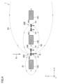
- FIG. 4 is a cross-sectional view showing a state in which a magnetic field generated from each bus bar in a current sensor according to embodiment 1 of the present invention is detected by a first magnetic detection element of a first sensor unit.
- FIG. 5 is a cross-sectional view showing a state in which a magnetic field generated from each bus bar in a current sensor according to embodiment 1 of the present invention is detected by a second magnetic detection element of a first sensor unit.
- the magnetic field B11 detected by the first magnetic detection element 30A is the sum of the magnetic fields generated by each bus bar and the external magnetic field.
- a first magnetic field B1 is generated around the first bus bar 10A.
- a second magnetic field B2 is generated around the second bus bar 10B.
- a third magnetic field B3 is generated around the third bus bar 10C.
- B1 (k/a) I1 .
- the second magnetic field B2 of the second busbar 10B is detected by the first magnetic detection element 30A
- the third magnetic field B3 of the third busbar 10C is detected by the first magnetic detection element 30A
- the magnetic field B12 of the second magnetic detection element 30B is also expressed by equation (2) using the respective relational expressions, in the same manner as in the case of the first magnetic detection element 30A.
- the measurement value of the magnetic field B11 detected by the first magnetic detection element 30A and the measurement value of the magnetic field B12 detected by the second magnetic detection element 30B can be processed by the calculation unit 40.
- the calculation unit 40 can calculate the value of a current flowing through the third busbar 10C (one busbar to be measured) based on a differential output value between the measurement value of the first magnetic detection element 30A and the measurement value of the second magnetic detection element 30B in the first sensor unit 20A.
- the current value I3 of the third current flowing through the third busbar 10C is calculated by the following formula.
- the difference between the measurement value of the first magnetic detection element 30A and the measurement value of the second magnetic detection element 30B can be expressed by multiplying the current value I3 of the third current flowing through the third bus bar 10C by a coefficient.
- the difference between the measurement value of the first magnetic detection element 30A and the measurement value of the second magnetic detection element 30B, i.e., the measurement value V1 detected and calculated in the first sensor unit 20A, can be expressed in proportional relationship with the current value I3 as shown in formula (5), so that the first sensor unit 20A can measure the current value I3 flowing through the third bus bar 10C.
- the measured value of the magnetic field detected by the third magnetic detection element 30C and the measured value of the magnetic field detected by the fourth magnetic detection element 30D are processed by the calculation unit 40.
- the value of the current flowing through the first bus bar 10A (one of the two bus bars other than the one bus bar to be measured) can be calculated based on the differential output value between the measured value of the third magnetic detection element 30C and the measured value of the fourth magnetic detection element 30D in the second sensor unit 20B.
- the value of the current flowing through the first bus bar 10A is calculated in the same manner as in the first sensor unit 20A.
- the measurement value V2 detected and calculated in the second sensor unit 20B can be expressed in a proportional relationship with the current value I1 , so that the second sensor unit 20B can measure the current value I1 flowing through the first bus bar 10A.
- the calculation unit 40 can calculate the current value flowing through the other of the two bus bars other than the bus bar to be measured by adding the current value I3 flowing through the third bus bar 10C (the bus bar to be measured) and the current value I1 flowing through the first bus bar 10A (one of the two bus bars other than the bus bar to be measured).
- the current value I2 flowing through the second busbar 10B can be calculated from the measurement value V1 detected and calculated in the first sensor unit 20A and the measurement value V2 detected and calculated in the second sensor unit 20B.
- the magnetic fields in the first bus bar 10A, the second bus bar 10B, and the third bus bar 10C are measured by the first sensor unit 20A and the second sensor unit 20B, respectively, so that the current value I3 flowing through the third bus bar 10C can be calculated based on the measurement value of the magnetic field measured by the first sensor unit 20A, the current value I1 flowing through the first bus bar 10A can be calculated based on the measurement value of the magnetic field measured by the second sensor unit 20B, and the current value I2 flowing through the second bus bar 10B can be calculated based on the calculated current value I3 and current value I1 .
- circuit configuration of the current sensor 1 according to this embodiment will be described, but the circuit configuration of the current sensor 1 according to this embodiment is not limited to the following configuration.
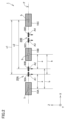
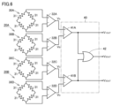
- FIG. 6 is a circuit diagram that shows a schematic circuit configuration of a current sensor according to the first embodiment of the present invention.
- the first magnetic detection element 30A, the second magnetic detection element 30B, the third magnetic detection element 30C, and the fourth magnetic detection element 30D each have a Wheatstone bridge type bridge circuit consisting of four tunnel type magnetoresistance elements 31.
- the detection signal of the first magnetic detection element 30A is outputted as a first voltage signal indicating a first output value (V A ) via a first amplifier 32A.
- the detection signal of the second magnetic detection element 30B is outputted as a second voltage signal indicating a second output value (V B ) via a second amplifier 32B.
- the detection signal of the third magnetic detection element 30C is outputted as a third voltage signal indicating a third output value (V C ) via a third amplifier 32C.
- the detection signal of the fourth magnetic detection element 30D is outputted as a fourth voltage signal indicating a fourth output value (V D ) via a fourth amplifier 32D.
- the first amplifier 32A, the second amplifier 32B, the third amplifier 32C and the fourth amplifier 32D are each constituted by an operational amplifier that performs differential amplification.
- the calculation unit 40 is an analog circuit configured by connecting circuit elements such as an amplifier.
- the calculation unit 40 receives a first voltage signal indicating a first output value ( VA ), a second voltage signal indicating a second output value ( VB ), a third voltage signal indicating a third output value ( VC ), and a fourth voltage signal indicating a fourth output value ( VD ), and outputs a first output voltage signal (V1OUT) corresponding to a current (detection) value ( I3 ) of the third current, a second output voltage signal ( V2OUT ) corresponding to a current (detection) value ( I2 ) of the second current, and a third output voltage signal ( V3OUT ) corresponding to a current (detection) value ( I1 ) of the first current in response to these input signals.
- the calculation unit 40 has a first differential amplifier 41A, a second differential amplifier 41B, and a summing amplifier 42.
- a first voltage signal indicating a first output value (V A ) is input to the non-inverting input terminal (+) of the first differential amplifier 41A, and a second voltage signal indicating a second output value (V B ) is input to the inverting input terminal (-).
- the first differential amplifier 41A outputs a first output voltage signal (V 1OUT ).
- the calculation unit 40 can output the first output voltage signal (V 1OUT ) as a voltage signal corresponding to the current (detected) value (I 3 ) of the third current.
- a third voltage signal indicating a third output value (V C ) is input to the non-inverting input terminal (+) of the second differential amplifier 41B, and a fourth voltage signal indicating a fourth output value (V D ) is input to the inverting input terminal (-).
- the second differential amplifier 41B outputs a third output voltage signal (V 3OUT ).
- the calculation unit 40 can output the third output voltage signal (V 3OUT ) as a voltage signal corresponding to the current (detected) value (I 1 ) of the first current.
- the first output voltage signal ( V1OUT ) and the third output voltage signal ( V3OUT ) are input to the summing amplifier 42.
- the summing amplifier 42 outputs a second output voltage signal ( V2OUT ).
- the calculation unit 40 can output the second output voltage signal ( V2OUT ) as a voltage signal corresponding to the current (detected) value ( I2 ) of the second current.
- a first sensor unit 20A and a second sensor unit 20B each including two magnetic detection elements are arranged between each bus bar of a three-phase AC current.
- the two magnetic detection elements are arranged so that the distance between one magnetic detection element and one of the two bus bars other than the measurement target, and the distance between the other magnetic detection element and the other of the two bus bars other than the measurement target, are approximately equal.
- the two magnetic detection elements detect the magnetic field generated from the current flowing through each bus bar, and the calculation unit 40 calculates the differential output value of the current value measured by the two magnetic detection elements.
- the current sensor 1 there is no need to provide a shielding member for each bus bar and each sensor unit to block external magnetic fields, so compared to a case in which a shielding member is provided, a simpler configuration and a lower-cost current sensor can be constructed.
- the overall size of the current sensor 1 can be reduced while improving measurement accuracy and responsiveness by using a TMR element, a GMR element, an AMR element, or a Hall element.
- the bus bars and sensor units can be arranged on a single plane to form a current sensor 1 with a low height.
- FIG. 7 is a cross-sectional view showing the configuration of a current sensor according to embodiment 2 of the present invention.
- a current sensor 1A according to embodiment 2 of the present invention includes a first bus bar 10A, a second bus bar 10B, a third bus bar 10C, a first sensor unit 20A, a second sensor unit 50B, and a calculation unit.
- the first sensor unit 20A measures the third bus bar 10C as one of the bus bars to be measured.
- the second sensor unit 50B measures one of the two bus bars other than the one bus bar to be measured.
- the second sensor unit 50B measures the second bus bar 10B as one of the two bus bars other than the one bus bar to be measured.
- the second sensor unit 50B is disposed between the bus bar to be measured and the other of the two bus bars other than the one to be measured.
- the second sensor unit 50B is disposed between the third bus bar 10C and the first bus bar 10A, which is the other of the two bus bars other than the one to be measured.
- the second sensor unit 50B includes a third magnetic detection element 60C and a fourth magnetic detection element 60D.
- the third magnetic detection element 60C and the fourth magnetic detection element 60D each have a sensitivity axis facing in the third direction (Z direction). Specifically, the third magnetic detection element 60C has a third sensitivity axis A3 facing in the third direction (Z direction). The fourth magnetic detection element 60D has a fourth sensitivity axis A4 facing in the third direction (Z direction).
- the third magnetic detection element 60C and the fourth magnetic detection element 60D are aligned in the second direction (X direction).
- the third magnetic detection element 60C and the fourth magnetic detection element 60D are aligned in the second direction (X direction) with their positions in the third direction (Z direction) being approximately the same.
- Each of the first magnetic detection element 30A, the second magnetic detection element 30B, the third magnetic detection element 60C, and the fourth magnetic detection element 60D is capable of detecting a magnetic field generated by a current flowing through the first bus bar 10A, the second bus bar 10B, and the third bus bar 10C.
- the calculation unit calculates the current values of the first bus bar 10A, the second bus bar 10B, and the third bus bar 10C from the output values of the first sensor unit 20A and the second sensor unit 50B.
- each bus bar and each magnetic detection element will be described below. As shown in FIG. 7, when viewed from the first direction (Y direction), the distance d between the third magnetic detection element 60C and the first bus bar 10A (the other of the two bus bars other than the one bus bar to be measured) and the distance d between the fourth magnetic detection element 60D and the third bus bar 10C (the one bus bar to be measured) are approximately equal.
- the distance e between the third magnetic detection element 60C and the third bus bar 10C (the bus bar to be measured) and the distance e between the fourth magnetic detection element 60D and the first bus bar 10A (the other of the two bus bars other than the bus bar to be measured) are approximately equal.
- the third magnetic detection element 60C and the second bus bar 10B are positioned at a distance f1. Also, when viewed from the first direction (Y direction), the fourth magnetic detection element 60D and the second bus bar 10B are positioned at a distance f2. Note that the distances f1 and f2 may be different from each other.
- the first sensor unit 20A can measure a current value ( I3 ) flowing through the third bus bar 10C.
- the second sensor unit 50B can measure a current value ( I2 ) flowing through the second bus bar 10B.
- the current value ( I1 ) flowing through the first bus bar 10A is calculated from the current values measured by the first sensor unit 20A and the second sensor unit 50B.
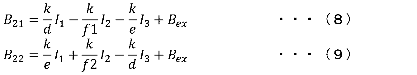
- the first sensor unit 20A, the second sensor unit 50B and the calculation unit can calculate the current value flowing through each busbar 10 based on the measurement value V1 detected and calculated by the first sensor unit 20A, the magnetic field B21 detected by the third magnetic detection element 60C of the second sensor unit 50B and the magnetic field B22 detected by the fourth magnetic detection element 60D, based on the following equations (8 ) to (14).
- a first sensor unit 20A and a second sensor unit 50B each including two magnetic detection elements are arranged between each bus bar of a three-phase AC current.
- the two magnetic detection elements are arranged so that the distance between one magnetic detection element and one of the two bus bars other than the measurement target, and the distance between the other magnetic detection element and the other of the two bus bars other than the measurement target, are approximately equal.
- the two magnetic detection elements detect the magnetic field generated from the current flowing through each bus bar, and the calculation unit calculates the differential output value of the current value measured by the two magnetic detection elements.
- the two sensor units each measure the current values of the two bus bars to be measured.
- the measurement value of the remaining bus bar is calculated from the current value measured by each sensor unit based on the relationship of the three-phase AC current.
- This allows the measured values in each sensor unit to be expressed only by the current value of the object to be measured while canceling the effects of external magnetic fields without using a shielding material to block external magnetic fields, so there is no need for advance preparations such as measuring the current value of each bus bar in advance to obtain parameters.
- complex calculations based on the parameters are not required. As a result, the overall size of the current sensor 1A can be reduced while improving measurement accuracy and responsiveness.
- first bus bar, second bus bar, and third bus bar each have approximately the same cross-sectional area in order to facilitate uniformity of the amount of current flowing through them.
- 1, 1A current sensor 10A first bus bar, 10B second bus bar, 10C third bus bar, 20A first sensor unit, 20B, 50B second sensor unit, 30A first magnetic detection element, 30B second magnetic detection element, 30C, 60C third magnetic detection element, 30D, 60D fourth magnetic detection element, 31 tunnel type magnetoresistance element, 32A first amplifier, 32B second amplifier, 32C third amplifier, 32D fourth amplifier, 40 calculation unit, 41A first differential amplifier, 41B second differential amplifier, 42 summing amplifier, A1 first sensitivity axis, A2 second sensitivity axis, A3 third sensitivity axis, A4 fourth sensitivity axis, F virtual plane.
Landscapes
- Physics & Mathematics (AREA)
- General Physics & Mathematics (AREA)
- Condensed Matter Physics & Semiconductors (AREA)
- Measuring Instrument Details And Bridges, And Automatic Balancing Devices (AREA)
Abstract
三相交流の電流が流れる第1バスバ(10A)、第2バスバ(10B)および第3バスバ(10C)と、第1磁気検出素子(30A)および第2磁気検出素子(30B)を有する第1センサユニット(20A)と、第3磁気検出素子(30C)および第4磁気検出素子(30D)を有する第2センサユニット(20B)を備え、第1センサユニット(20A)は、第1~第3バスバのうちの任意の一の測定対象のバスバ以外の2つのバスバ同士の間に配置され、第2センサユニット(20B)は、一の測定対象のバスバ以外の2つのバスバのうちの一方を測定対象とし、一の測定対象のバスバと一の測定対象のバスバ以外の2つのバスバのうちの他方との間に配置され、第1磁気検出素子(30A)と一の測定対象のバスバ以外の2つのバスバのうちの一方との距離と第2磁気検出素子(30B)と一の測定対象のバスバ以外の2つのバスバのうちの他方との距離は略等距離であり、第3磁気検出素子(30C)と一の測定対象のバスバ以外の2つのバスバのうちの他方との距離と第4磁気検出素子(30D)と一の測定対象のバスバとの距離は略等距離である電流センサ。
Description
本発明は、電流センサに関する。
電流測定装置の構成を開示した先行技術文献として、特開2008-58035号公報(特許文献1)がある。特許文献1に記載された電流測定装置は、総和がゼロとなる電流が流れる3本の導体の各導体の電流値を測定する。電流測定装置は、第1および第2のコアレス電流センサと、保持手段と、算出手段と、シールド部材とを備える。第1および第2のコアレス電流センサは、3本の導体に対して所定の相対位置に配置される。保持手段は、3本の導体を介して流れる電流を測定する前の準備段階において、その測定に必要な係数を取得し、保持する。算出手段は、3本の導体を介して流れる電流値の総和がゼロであることを利用して、第1および第2のコアレス電流センサの出力信号および保持手段に保持されている係数に基づいて、各導体を介して流れる電流値を算出する。シールド部材は、各導体および第1および第2のコアレス電流センサを取り囲む。
特許文献1に記載された電流測定装置においては、シールド部材が設けられるため、装置が大型化するとともに、シールド部材の影響によって電流の測定精度が低下する。また、当該装置は、各導体の電流値が予め取得したパラメータに基づいて算出されることにより、複雑な計算が必要となる。このため、電流値の計算時間が長くなることによって、電流測定の応答性が低下する。
本発明は上記の問題点に鑑みてなされたものであって、全体のサイズを小型化しつつ、測定精度および応答性を向上させることができる電流センサを提供することを目的とする。
本発明に基づく電流センサは、第1バスバ、第2バスバおよび第3バスバと、第1センサユニットと、第2センサユニットと、算出部とを備える。第1バスバ、第2バスバおよび第3バスバは、互いに間隔をあけつつ第1の方向に各々延在し、かつ第1の方向に直交する第2の方向に並び、三相交流の電流が流れる。第1センサユニットは、第1バスバ、第2バスバおよび第3バスバのうちの任意の一の測定対象のバスバ以外の2つのバスバ同士の間に配置される。第2センサユニットは、一の測定対象のバスバ以外の2つのバスバのうちの一方を測定対象とし、一の測定対象のバスバと一の測定対象のバスバ以外の2つのバスバのうちの他方との間に配置される。算出部は、第1センサユニットおよび第2センサユニットの各々の出力値から第1バスバ、第2バスバおよび第3バスバの各々の電流値を算出する。第1センサユニットは、第1磁気検出素子および第2磁気検出素子を含む。第1磁気検出素子および第2磁気検出素子は、第1の方向および第2の方向に直交する第3の方向に向いた感度軸を各々有し、第2の方向に並び、かつ第1バスバ、第2バスバおよび第3バスバを流れる電流により発生する磁界を検出する。第2センサユニットは、第3磁気検出素子および第4磁気検出素子を含む。第3磁気検出素子および第4磁気検出素子は、第3の方向に向いた感度軸を各々有し、第2の方向に並び、かつ第1バスバ、第2バスバおよび第3バスバを流れる電流により発生する磁界を検出する。第1の方向から見て、第1磁気検出素子と一の測定対象のバスバ以外の2つのバスバのうちの一方との距離、および、第2磁気検出素子と一の測定対象のバスバ以外の2つのバスバのうちの他方との距離は、略等距離である。第1の方向から見て、第3磁気検出素子と一の測定対象のバスバ以外の2つのバスバのうちの他方との距離、および、第4磁気検出素子と一の測定対象のバスバとの距離は、略等距離である。算出部は、第1センサユニットにおける第1磁気検出素子の測定値と第2磁気検出素子の測定値との差動出力値に基づき一の測定対象のバスバを流れる電流値を算出可能であり、第2センサユニットにおける第3磁気検出素子の測定値と第4磁気検出素子の測定値との差動出力値に基づき一の測定対象のバスバ以外の2つのバスバのうちの一方を流れる電流値を算出可能であり、かつ、一の測定対象のバスバを流れる電流値と一の測定対象のバスバ以外の2つのバスバのうちの一方を流れる電流値とを加算することによって、一の測定対象のバスバ以外の2つのバスバのうちの他方を流れる電流値を算出可能である。
本発明によれば、電流センサの全体のサイズを小型化しつつ、測定精度および応答性を向上させることができる。
以下、本発明の各実施の形態に係る電流センサについて図を参照して説明する。以下の実施の形態の説明においては、図中の同一または相当部分には同一符号を付して、その説明は繰り返さない。
なお、図面においては、各バスバが並ぶ方向を第2の方向としてのX方向、各バスバが延在する方向を第1の方向としてのY方向、各磁気検出素子の感度軸に沿う方向を第3の方向としてのZ方向とする。また、電流センサにおける各構成要素間の距離とは、各構成要素の中心同士を結ぶ距離とする。
(実施の形態1)
図1は、本発明の実施の形態1に係る電流センサの構成を示す斜視図である。図2は、本発明の実施の形態1に係る電流センサの構成を示す断面図である。図3は、本発明の実施の形態1に係る電流センサにおける各構成の電気的な接続を示すブロック図である。
図1は、本発明の実施の形態1に係る電流センサの構成を示す斜視図である。図2は、本発明の実施の形態1に係る電流センサの構成を示す断面図である。図3は、本発明の実施の形態1に係る電流センサにおける各構成の電気的な接続を示すブロック図である。
図1~図3に示すように、本発明の実施の形態1に係る電流センサ1は、第1バスバ10Aと、第2バスバ10Bと、第3バスバ10Cと、第1センサユニット20Aと、第2センサユニット20Bと、算出部40とを備える。
第1バスバ10A、第2バスバ10Bおよび第3バスバ10Cは、三相三線式のバスバである。第1バスバ10A、第2バスバ10Bおよび第3バスバ10Cの各々には、三相交流の電流が流れる。第1バスバ10A、第2バスバ10Bおよび第3バスバ10Cの各々を流れる電流は、振幅が等しく互いに位相が120°ずつずれた交流電流を構成している。
第1バスバ10Aを第1の方向(Y方向)に流れる第1電流の電流値(I1)、第2バスバ10Bを第1の方向(Y方向)に流れる第2電流の電流値(I2)、および、第3バスバ10Cを第1の方向(Y方向)に流れる第3電流の電流値(I3)においては、I1+I2+I3=0の関係が成立している。たとえば、第1電流がU相の交流電流、第2電流がV相の交流電流、第3電流がW相の交流電流であってもよい。
第1バスバ10A、第2バスバ10Bおよび第3バスバ10Cの各々は、第1の方向(Y方向)に直交する第2の方向(X方向)において互いに間隔をあけつつ並んでいる。本実施の形態においては、第2の方向(X方向)において、第3バスバ10Cは、第2バスバ10Bとの間の距離が、第1バスバ10Aと第2バスバ10Bとの間の距離に等しくなるように並んでいる。なお、第2の方向(X方向)において、第1バスバ10Aと第2バスバ10Bとの間の距離および第2バスバ10Bと第3バスバ10Cの間の距離は、異なっていてもよい。
第1バスバ10Aは、第1の方向(Y方向)に沿って直線状に延在している。第1バスバ10Aを流れる第1電流の電流値(I1)は、交流電流であるため、正の値または負の値をとり得る。
第2バスバ10Bは、第1の方向(Y方向)に沿って直線状に延在している。第2バスバ10Bを流れる第2電流の電流値(I2)は、交流電流であるため、正の値または負の値をとり得る。
第3バスバ10Cは、第1の方向(Y方向)に沿って直線状に延在している。第3バスバ10Cを流れる第3電流の電流値(I3)は、交流電流であるため、正の値または負の値をとり得る。
第1センサユニット20Aは、第1バスバ10A、第2バスバ10Bおよび第3バスバ10Cのうちの任意の一の測定対象のバスバ以外の2つのバスバ同士の間に配置される。本実施の形態においては、第1センサユニット20Aは、一の測定対象のバスバとして第3バスバ10Cを測定対象とする。このため、第1センサユニット20Aは、第1バスバ10Aおよび第2バスバ10Bの間に配置されている。第1センサユニット20Aは、たとえば、図示しない基板上に配置される。なお、第1センサユニット20Aは、樹脂モールドなどによってその位置が固定されてもよい。
第1センサユニット20Aは、第1磁気検出素子30Aと、第2磁気検出素子30Bとを含む。第1磁気検出素子30Aおよび第2磁気検出素子30Bの各々は、第1バスバ10A、第2バスバ10Bおよび第3バスバ10Cを流れる電流により発生する磁界を検出可能である。
第1磁気検出素子30Aおよび第2磁気検出素子30Bは、第1の方向(Y方向)および第2の方向(X方向)に直交する第3の方向(Z方向)に向いた感度軸を各々有する。具体的には、第1磁気検出素子30Aは、第3の方向(Z方向)に向いた第1感度軸A1を有する。第2磁気検出素子30Bは、第3の方向(Z方向)に向いた第2感度軸A2を有する。
第1磁気検出素子30Aおよび第2磁気検出素子30Bは、第2の方向(X方向)に並んでいる。本実施の形態においては、第1磁気検出素子30Aおよび第2磁気検出素子30Bは、第3の方向(Z方向)における位置を略同じにして、第2の方向(X方向)に並んでいる。
第2センサユニット20Bは、上記一の測定対象のバスバ以外の2つのバスバのうちの一方を測定対象とする。本実施の形態における第2センサユニット20Bは、一の測定対象のバスバ以外の2つのバスバのうちの一方として第1バスバ10Aを測定対象とする。
第2センサユニット20Bは、上記一の測定対象のバスバと上記一の測定対象のバスバ以外の2つのバスバのうちの他方との間に配置される。本実施の形態における第2センサユニット20Bは、第3バスバ10Cと一の測定対象のバスバ以外の2つのバスバのうちの他方としての第2バスバ10Bとの間に配置されている。第2センサユニット20Bは、たとえば、図示しない基板上に配置される。なお、第2センサユニット20Bは、樹脂モールドなどによってその位置が固定されてもよい。
第2センサユニット20Bは、第3磁気検出素子30Cと、第4磁気検出素子30Dとを含む。第3磁気検出素子30Cおよび第4磁気検出素子30Dの各々は、第1バスバ10A、第2バスバ10Bおよび第3バスバ10Cを流れる電流により発生する磁界を検出可能である。
第3磁気検出素子30Cおよび第4磁気検出素子30Dは、第3の方向(Z方向)に向いた感度軸を各々有する。具体的には、第3磁気検出素子30Cは、第3の方向(Z方向)に向いた第3感度軸A3を有する。第4磁気検出素子30Dは、第3の方向(Z方向)に向いた第4感度軸A4を有する。
第3磁気検出素子30Cおよび第4磁気検出素子30Dは、第2の方向(X方向)に並んでいる。本実施の形態においては、第3磁気検出素子30Cおよび第4磁気検出素子30Dは、第3の方向(Z方向)における位置を略同じにして、第2の方向(X方向)に並んでいる。
第1センサユニット20Aおよび第2センサユニット20Bにおける、第1磁気検出素子30A、第2磁気検出素子30B、第3磁気検出素子30Cおよび第4磁気検出素子30Dの少なくとも1つは、少なくとも2つ以上の磁気抵抗素子からなる回路を有していてもよい。第1磁気検出素子30A、第2磁気検出素子30B、第3磁気検出素子30Cおよび第4磁気検出素子30Dの各々のいずれもが、少なくとも2つ以上の磁気抵抗素子からなる回路を有していてもよい。少なくとも2つ以上の磁気抵抗素子からなる回路は、2つの磁気抵抗素子からなるハーフブリッジ回路であってもよいし、4つの磁気抵抗素子からなるホイートストンブリッジ型のブリッジ回路であってもよい。
また、上記磁気抵抗素子は、トンネル型磁気抵抗(Tunnel Magneto Resistance(TMR))素子、巨大磁気抵抗(Giant Magneto Resistance(GMR))素子、または、異方性磁気抵抗(Anisotropic Magnetic Resistance(AMR))素子のいずれであってもよい。
第1磁気検出素子30A、第2磁気検出素子30Bおよび第3磁気検出素子30Cのうちの少なくとも1つが、ホール素子を有してもよい。第1磁気検出素子30A、第2磁気検出素子30B、第3磁気検出素子30Cおよび第4磁気検出素子30Dの各々のいずれもが、ホール素子を有してもよい。
第1バスバ10A、第2バスバ10B、第3バスバ10C、第1センサユニット20Aおよび第2センサユニット20Bの各々は、第1の方向(Y方向)および第2の方向(X方向)に沿う仮想平面F上に配置されている。
算出部40は、第1センサユニット20Aおよび第2センサユニット20Bの各々の出力値から第1バスバ10A、第2バスバ10Bおよび第3バスバ10Cの各々の電流値を算出する。
図3に示すように、第1センサユニット20Aおよび第2センサユニット20Bの各々は、配線によって、算出部40に電気的に接続されている。具体的には、第1磁気検出素子30A、第2磁気検出素子30B、第3磁気検出素子30Cおよび第4磁気検出素子30Dの各々が、算出部40に電気的に接続されている。
以下、各バスバと各センサユニットにおける各磁気検出素子との位置関係について説明する。
図2に示すように、第1の方向(Y方向)から見て、第1磁気検出素子30Aと第1バスバ10A(一の測定対象のバスバ以外の2つのバスバのうちの一方)との距離a、および、第2磁気検出素子30Bと第2バスバ10B(一の測定対象のバスバ以外の2つのバスバのうちの他方)との距離aは、略等距離である。なお、本実施の形態の距離に関する「略等距離」とは、電流センサの各構成要素を組み付ける際の製造工程における組み付け位置のばらつきを含む意味である。
第1の方向(Y方向)から見て、第1磁気検出素子30Aと第2バスバ10B(一の測定対象のバスバ以外の2つのバスバのうちの他方)との距離b、および、第2磁気検出素子30Bと第1バスバ10A(一の測定対象のバスバ以外の2つのバスバのうちの一方)との距離bは、略等距離である。
距離bは、距離aに対して、第1磁気検出素子30Aと第2磁気検出素子30Bとの間の距離を足したものになるため、第1磁気検出素子30Aと第1バスバ10Aとの距離a、および、第2磁気検出素子30Bと第2バスバ10Bとの距離aが略等距離であれば、第1磁気検出素子30Aと第2バスバ10Bとの距離b、および、第2磁気検出素子30Bと第1バスバ10Aとの距離bは、必然的に略等距離となる。
第1の方向(Y方向)から見て、第1磁気検出素子30Aと第3バスバ10C(一の測定対象のバスバ)とは、距離c1の位置に配置されている。また、第1の方向(Y方向)から見て、第2磁気検出素子30Bと第3バスバ10C(一の測定対象のバスバ)とは、距離c2の位置に配置されている。
第3磁気検出素子30Cおよび第4磁気検出素子30Dについては、第1の方向(Y方向)から見て、第3磁気検出素子30Cと第2バスバ10B(一の測定対象のバスバ以外の2つのバスバのうちの他方)との距離、および、第4磁気検出素子30Dと第3バスバ10C(一の測定対象のバスバ)との距離は、略等距離である。
第1の方向(Y方向)から見て、第3磁気検出素子30Cと第3バスバ10C(一の測定対象のバスバ)との距離、および、第4磁気検出素子30Dと第2バスバ10B(一の測定対象のバスバ以外の2つのバスバのうちの他方)との距離は、略等距離である。
第1の方向(Y方向)から見て、第1バスバ10A(一の測定対象のバスバ以外の2つのバスバのうちの一方)に対する第3磁気検出素子30Cおよび第4磁気検出素子30Dとの距離は、互いに異なる。
本実施の形態においては、各バスバおよび各センサユニットの間には、透磁率の高い磁性材料などからなる磁気遮蔽板、および、磁場を集磁するための軟磁性体などからなる磁性体コアは設けられていない。これにより、本実施の形態に係る電流センサ1は、全体のサイズを小型化できる。
以下、各センサユニットが測定対象のバスバ以外のバスバを含めた磁界を検出した場合でも、測定対象のバスバの電流値のみを測定できることについて説明する。
本実施の形態においては、第1センサユニット20Aは、第3バスバ10Cを流れる電流値(I3)を測定可能である。第2センサユニット20Bは、第1バスバ10Aを流れる電流値(I1)を測定可能である。第2バスバ10Bを流れる電流値(I2)は、第1センサユニット20Aおよび第2センサユニット20Bによって測定された電流値から算出される。各センサユニットにおいて対応するバスバを流れる電流値を測定することについて、第1センサユニット20Aにより第3バスバ10Cを流れる電流の電流値I3を測定する場合を例示して説明する。
図4は、本発明の実施の形態1に係る電流センサにおける各バスバから発生する磁界を第1センサユニットの第1磁気検出素子において検出する状態を示す断面図である。図5は、本発明の実施の形態1に係る電流センサにおける各バスバから発生する磁界を第1センサユニットの第2磁気検出素子において検出する状態を示す断面図である。
まず、図4に示すように、第1磁気検出素子30Aにより検出する磁界B11は、各バスバから発生する磁界および外部磁界を足し合わせたものとなる。第1電流が流れた際、第1バスバ10Aの周囲には、第1磁界B1が生じる。第2電流が流れた際、第2バスバ10Bの周囲には、第2磁界B2が生じる。第3電流が流れた際、第3バスバ10Cの周囲には、第3磁界B3が生じる。また、外部の影響により外部磁界Bexが生じている。このため、第1磁気検出素子30Aにより検出する磁界B11は、B11=B1+B2+B3+Bexと表される。
図2および図4に示すように、第1磁界B1は、磁束密度および磁界強度の関係から、透磁率μおよび距離aを用いて、B1=μ(1/2πa)I1と表される。上述の式において、μ(1/2π)を定数kと仮定すると、B1=(k/a)I1と表される。
同様に、第2バスバ10Bの第2磁界B2を第1磁気検出素子30Aにより検出する場合、第2磁界B2は、B2=μ(1/2πb)I2と表される。μ(1/2π)を定数kと仮定すると、B2=(k/b)I2と表される。また、第3バスバ10Cの第3磁界B3を第1磁気検出素子30Aにより検出する場合、第3磁界B3は、B3=μ(1/2πc1)I2と表される。μ(1/2π)を定数kと仮定すると、B3=(k/c1)I3と表される。
第1磁気検出素子30Aにより検出する磁界B11は、たとえば、第1感度軸A1が向く方向をプラス方向とした場合、B11=B1+B2+B3+Bexに上記の各式を代入して、式(1)により表される。また、図2および図5に示すように、第2磁気検出素子30Bの磁界B12についても、第1磁気検出素子30Aの場合と同様に、各関係式によって、式(2)により表される。

第1センサユニット20Aにおいて、第1磁気検出素子30Aにより検出する磁界B11の測定値、および第2磁気検出素子30Bにより検出する磁界B12の測定値は、算出部40によって処理することができる。具体的には、算出部40は、第1センサユニット20Aにおける第1磁気検出素子30Aの測定値と第2磁気検出素子30Bの測定値との差動出力値に基づき第3バスバ10C(一の測定対象のバスバ)を流れる電流値を算出可能である。第3バスバ10Cを流れる第3電流の電流値I3は、下記式によって算出される。

第1磁気検出素子30Aの測定値と第2磁気検出素子30Bの測定値との差動出力値を算出するため、第1磁気検出素子30Aおよび第2磁気検出素子30Bにおいて測定される外部磁界Bexは、互いに打ち消し合う。また、電流値I3の係数で示される(c1-c2)は、各バスバに対する第1磁気検出素子30Aの位置関係から、(b-a)と等しい。このため、上記式(3)に示すように、(c1-c2)を(b-a)に置き換えることによって、各バスバの電流値を、(b-a)を係数に含む式により表すことができる。
さらに、各バスバを流れる電流は、三相交流であり、I1+I2+I3=0の関係が成立している。このため、I1+I2=-I3を上記式に用いることによって、式(4)により表すことができる。
以上の式より、第1センサユニット20Aにおける第1磁気検出素子30Aの測定値と第2磁気検出素子30Bの測定値との差動出力値を算出することによって、第1磁気検出素子30Aの測定値と第2磁気検出素子30Bの測定値との差分は、第3バスバ10Cを流れる第3電流の電流値I3に係数をかけたものによって表すことができる。したがって、第1磁気検出素子30Aの測定値と第2磁気検出素子30Bの測定値との差分、すなわち、第1センサユニット20Aにおいて検出および算出される測定値V1は、式(5)に示すように、電流値I3と比例関係で表すことができるため、第1センサユニット20Aにおいて、第3バスバ10Cを流れる電流値I3を測定することが可能である。
第2センサユニット20Bにおいて、第3磁気検出素子30Cにより検出する磁界の測定値と第4磁気検出素子30Dにより検出する磁界の測定値とは、算出部40により処理される。具体的には、第2センサユニット20Bにおける第3磁気検出素子30Cの測定値と第4磁気検出素子30Dの測定値との差動出力値に基づき第1バスバ10A(一の測定対象のバスバ以外の2つのバスバのうちの一方)を流れる電流値を算出可能である。
第1バスバ10Aを流れる電流値は、第1センサユニット20Aにおける算出方法と同様に算出される。これにより、下記式(6)に示すように、第2センサユニット20Bにおいて検出および算出される測定値V2は、電流値I1と比例関係で表すことができるため、第2センサユニット20Bにおいて、第1バスバ10Aを流れる電流値I1を測定することが可能である。
さらに、算出部40は、第3バスバ10C(一の測定対象のバスバ)を流れる電流値I3と第1バスバ10A(一の測定対象のバスバ以外の2つのバスバのうちの一方)を流れる電流値I1とを加算することによって、一の測定対象のバスバ以外の2つのバスバのうちの他方を流れる電流値を算出可能である。
具体的には、第1センサユニット20Aにおいて検出および算出される測定値V1と第2センサユニット20Bにおいて検出および算出される測定値V2とを算出部40において加算し、I1+I2+I3=0の関係を用いて、下記式(7)を得ることができる。これにより、第2バスバ10Bを流れる電流値I2は、第1センサユニット20Aにおいて検出および算出される測定値V1と第2センサユニット20Bにおいて検出および算出される測定値V2とによって算出することができる。
上述した通り、本実施の形態においては、第1バスバ10A、第2バスバ10Bおよび第3バスバ10Cの各々における磁界を第1センサユニット20Aおよび第2センサユニット20Bにより測定することによって、第3バスバ10Cを流れる電流値I3が第1センサユニット20Aで測定される磁界の測定値に基づいて算出され、第1バスバ10Aを流れる電流値I1が第2センサユニット20Bで測定される磁界の測定値に基づいて算出され、算出された電流値I3および電流値I1に基づいて第2バスバ10Bを流れる電流値I2を算出することができる。これにより、各バスバ間にシールドを設けることなく、三相交流の各バスバの電流値を測定することができる。
次に、本実施の形態に係る電流センサ1の回路構成を説明するが、本実施の形態に係る電流センサ1の回路構成は、以下の構成に限定されない。
図6は、本発明の実施の形態1に係る電流センサの回路構成を概略的に示す回路図である。図6に示すように、本実施の形態において、第1磁気検出素子30A、第2磁気検出素子30B、第3磁気検出素子30C、および、第4磁気検出素子30Dは、それぞれ、4つのトンネル型磁気抵抗素子31からなるホイートストンブリッジ型のブリッジ回路を有する。
第1磁気検出素子30Aの検出信号は、第1アンプ32Aを介して、第1出力値(VA)を示す第1電圧信号として出力される。第2磁気検出素子30Bの検出信号は、第2アンプ32Bを介して、第2出力値(VB)を示す第2電圧信号として出力される。第3磁気検出素子30Cの検出信号は、第3アンプ32Cを介して、第3出力値(VC)を示す第3電圧信号として出力される。第4磁気検出素子30Dの検出信号は、第4アンプ32Dを介して、第4出力値(VD)を示す第4電圧信号として出力される。第1アンプ32A、第2アンプ32B、第3アンプ32Cおよび第4アンプ32Dは、それぞれ、差動増幅をするオペアンプにより構成される。
算出部40は、アンプ等の回路素子を接続して構成されるアナログ回路である。算出部40は、第1出力値(VA)を示す第1電圧信号、第2出力値(VB)を示す第2電圧信号、第3出力値(VC)を示す第3電圧信号、第4出力値(VD)を示す第4電圧信号が入力され、これらの入力信号に応じて、第3電流の電流(検出)値(I3)に対応する第1出力電圧信号(V1OUT)、第2電流の電流(検出)値(I2)に対応する第2出力電圧信号(V2OUT)、第1電流の電流(検出)値(I1)に対応する第3出力電圧信号(V3OUT)を出力する。
算出部40は、第1差動増幅器41Aと、第2差動増幅器41Bと、加算増幅器42とを有する。
第1差動増幅器41Aの非反転入力端子(+)には、第1出力値(VA)を示す第1電圧信号が入力され、反転入力端子(-)には、第2出力値(VB)を示す第2電圧信号が入力される。第1差動増幅器41Aは、第1出力電圧信号(V1OUT)を出力する。ここで、本実施の形態においては、上記式(5)が成立するため、算出部40は、第1出力電圧信号(V1OUT)を、第3電流の電流(検出)値(I3)に対応する電圧信号として出力することができる。
第2差動増幅器41Bの非反転入力端子(+)には、第3出力値(VC)を示す第3電圧信号が入力され、反転入力端子(-)には、第4出力値(VD)を示す第4電圧信号が入力される。第2差動増幅器41Bは、第3出力電圧信号(V3OUT)を出力する。ここで、本実施の形態においては、上記式(6)が成立するため、算出部40は、第3出力電圧信号(V3OUT)を、第1電流の電流(検出)値(I1)に対応する電圧信号として出力することができる。
加算増幅器42には、第1出力電圧信号(V1OUT)および第3出力電圧信号(V3OUT)が入力される。加算増幅器42は、第2出力電圧信号(V2OUT)を出力する。ここで、本実施の形態においては、上記式(7)が成立するため、算出部40は、第2出力電圧信号(V2OUT)を、第2電流の電流(検出)値(I2)に対応する電圧信号として出力することができる。
本発明の実施の形態1に係る電流センサ1においては、三相交流の各バスバを測定する際、三相交流の各バスバの間に2つの磁気検出素子を各々含む第1センサユニット20Aおよび第2センサユニット20Bを配置する。当該2つの磁気検出素子を、一方の磁気検出素子と測定対象以外の2つのバスバのうちの一方との距離、および、他方の磁気検出素子と測定対象以外の2つのバスバのうちの他方との距離が略等距離になるように配置する。当該2つの磁気検出素子によって各バスバに流れる電流から発生する磁界を検出し、算出部40において当該2つの磁気検出素子により測定される電流値の差動出力値を算出する。これにより、各センサユニットにおいて検出される磁界の測定値を、各バスバのうちの測定対象のバスバの電流値に比例する値のみで表すことができる。2つのセンサユニットの各々によって、測定対象の2つのバスバの電流値を測定する。残りの1つのバスバの測定値は、三相交流の電流の関係から、各センサユニットで測定された電流値から算出する。これにより、外部磁場を遮断するシールド部材を使用することなく、外部磁場の影響をキャンセルしつつ、各センサユニットにおける測定値が測定対象の電流値のみにより表すことができるため、事前に各バスバの電流値を測定してパラメータを取得するなどの事前準備を必要としない。また、当該パラメータに基づいた複雑な計算を必要としない。その結果、電流センサ1の全体のサイズを小型化しつつ、測定精度および応答性を向上させることができる。
本発明の実施の形態1に係る電流センサ1においては、各バスバおよび各センサユニットに対して外部磁界を遮断するシールド部材を設ける必要がないため、シールド部材を設ける場合と比較して、簡易な構成とすることができ、かつ、低コストの電流センサを構成することができる。
本発明の実施の形態1に係る電流センサ1においては、TMR素子、GMR素子、AMR素子またはホール素子により、電流センサ1の全体のサイズを小型化しつつ、測定精度および応答性を向上させることができる。
本発明の実施の形態1に係る電流センサ1においては、各バスバおよび各センサユニットを一平面上に並べて、高さ方向に低背化した電流センサ1を構成することができる。
(実施の形態2)
以下、本発明の実施の形態2に係る電流センサについて図を参照して説明する。本発明の実施の形態2に係る電流センサは、第2センサユニットの配置が本発明の実施の形態1に係る電流センサ1と異なるため、本発明の実施の形態1に係る電流センサ1と同様である構成については説明を繰り返さない。
以下、本発明の実施の形態2に係る電流センサについて図を参照して説明する。本発明の実施の形態2に係る電流センサは、第2センサユニットの配置が本発明の実施の形態1に係る電流センサ1と異なるため、本発明の実施の形態1に係る電流センサ1と同様である構成については説明を繰り返さない。
図7は、本発明の実施の形態2に係る電流センサの構成を示す断面図である。図7に示すように、本発明の実施の形態2に係る電流センサ1Aは、第1バスバ10Aと、第2バスバ10Bと、第3バスバ10Cと、第1センサユニット20Aと、第2センサユニット50Bと、算出部とを備える。第1センサユニット20Aは、一の測定対象のバスバとして第3バスバ10Cを測定対象とする。
第2センサユニット50Bは、上記一の測定対象のバスバ以外の2つのバスバのうちの一方を測定対象とする。本実施の形態における第2センサユニット50Bは、一の測定対象のバスバ以外の2つのバスバのうちの一方として第2バスバ10Bを測定対象とする。
第2センサユニット50Bは、上記一の測定対象のバスバと上記一の測定対象のバスバ以外の2つのバスバのうちの他方との間に配置される。本実施の形態における第2センサユニット50Bは、第3バスバ10Cと一の測定対象のバスバ以外の2つのバスバのうちの他方としての第1バスバ10Aとの間に配置されている。
第2センサユニット50Bは、第3磁気検出素子60Cおよび第4磁気検出素子60Dを含む。
第3磁気検出素子60Cおよび第4磁気検出素子60Dは、第3の方向(Z方向)に向いた感度軸を各々有する。具体的には、第3磁気検出素子60Cは、第3の方向(Z方向)に向いた第3感度軸A3を有する。第4磁気検出素子60Dは、第3の方向(Z方向)に向いた第4感度軸A4を有する。
第3磁気検出素子60Cおよび第4磁気検出素子60Dは、第2の方向(X方向)に並んでいる。本実施の形態においては、第3磁気検出素子60Cおよび第4磁気検出素子60Dは、第3の方向(Z方向)における位置を略同じにして、第2の方向(X方向)に並んでいる。
第1磁気検出素子30A、第2磁気検出素子30B、第3磁気検出素子60Cおよび第4磁気検出素子60Dの各々は、第1バスバ10A、第2バスバ10Bおよび第3バスバ10Cを流れる電流により発生する磁界を検出可能である。
算出部は、第1センサユニット20Aおよび第2センサユニット50Bの各々の出力値から第1バスバ10A、第2バスバ10Bおよび第3バスバ10Cの各々の電流値を算出する。
以下、各バスバと各磁気検出素子の位置関係について説明する。図7に示すように、第1の方向(Y方向)から見て、第3磁気検出素子60Cと第1バスバ10A(一の測定対象のバスバ以外の2つのバスバのうちの他方)との距離d、および、第4磁気検出素子60Dと第3バスバ10C(一の測定対象のバスバ)との距離dは、略等距離である。
第1の方向(Y方向)から見て、第3磁気検出素子60Cと第3バスバ10C(一の測定対象のバスバ)との距離e、および、第4磁気検出素子60Dと第1バスバ10A(一の測定対象のバスバ以外の2つのバスバのうちの他方)との距離eは、略等距離である。
第1の方向(Y方向)から見て、第3磁気検出素子60Cと第2バスバ10B(一の測定対象のバスバ以外の2つのバスバのうちの一方)とは、距離f1の位置に配置されている。また、第1の方向(Y方向)から見て、第4磁気検出素子60Dと第2バスバ10Bとは、距離f2の位置に配置されている。なお、距離f1と距離f2とは、互いに距離が異なっていてもよい。
本実施の形態においては、第1センサユニット20Aは、第3バスバ10Cを流れる電流値(I3)を測定可能である。第2センサユニット50Bは、第2バスバ10Bを流れる電流値(I2)を測定可能である。第1バスバ10Aを流れる電流値(I1)は、第1センサユニット20Aおよび第2センサユニット50Bによって測定された電流値から算出される。
実施の形態1と同様にして、第1センサユニット20A、第2センサユニット50Bおよび算出部によって、以下の式(8)~式(14)に基づき、第1センサユニット20Aにおいて検出および算出される測定値V1、第2センサユニット50Bの第3磁気検出素子60Cにより検出する磁界B21および第4磁気検出素子60Dにより検出する磁界B22に基づき算出される測定値V2から、各バスバ10を流れる電流値を算出することができる。

本発明の実施の形態2に係る電流センサ1Aにおいては、三相交流の各バスバを測定する際、三相交流の各バスバの間に2つの磁気検出素子を各々含む第1センサユニット20Aおよび第2センサユニット50Bを配置する。当該2つの磁気検出素子を、一方の磁気検出素子と測定対象以外の2つのバスバのうちの一方との距離、および、他方の磁気検出素子と測定対象以外の2つのバスバのうちの他方との距離が略等距離になるように配置する。当該2つの磁気検出素子によって各バスバに流れる電流から発生する磁界を検出し、算出部において当該2つの磁気検出素子により測定される電流値の差動出力値を算出する。これにより、各センサユニットにおいて検出される磁界の測定値を、各バスバのうちの測定対象のバスバの電流値に比例する値のみで表すことができる。2つのセンサユニットの各々によって、測定対象の2つのバスバの電流値を測定する。残りの1つのバスバの測定値は、三相交流の電流の関係から、各センサユニットで測定された電流値から算出する。これにより、外部磁場を遮断するシールド部材を使用することなく、外部磁場の影響をキャンセルしつつ、各センサユニットにおける測定値が測定対象の電流値のみにより表すことができるため、事前に各バスバの電流値を測定してパラメータを取得するなどの事前準備を必要としない。また、当該パラメータに基づいた複雑な計算を必要としない。その結果、電流センサ1Aの全体のサイズを小型化しつつ、測定精度および応答性を向上させることができる。
なお、第1バスバ、第2バスバおよび第3バスバの各々は、流れる電流の量を均一にしやすくするため、これらの断面積が略同じであることが望ましい。
上述した実施の形態の説明において、組み合わせ可能な構成を相互に組み合わせてもよい。
今回開示された実施の形態はすべての点で例示であって制限的なものではないと考えられるべきである。本発明の範囲は上記した説明ではなくて請求の範囲によって示され、請求の範囲と均等の意味および範囲内でのすべての変更が含まれることが意図される。
1,1A 電流センサ、10A 第1バスバ、10B 第2バスバ、10C 第3バスバ、20A 第1センサユニット、20B,50B 第2センサユニット、30A 第1磁気検出素子、30B 第2磁気検出素子、30C,60C 第3磁気検出素子、30D,60D 第4磁気検出素子、31 トンネル型磁気抵抗素子、32A 第1アンプ、32B 第2アンプ、32C 第3アンプ、32D 第4アンプ、40 算出部、41A 第1差動増幅器、41B 第2差動増幅器、42 加算増幅器、A1 第1感度軸、A2 第2感度軸、A3 第3感度軸、A4 第4感度軸、F 仮想平面。
Claims (6)
- 互いに間隔をあけつつ第1の方向に各々延在し、かつ前記第1の方向に直交する第2の方向に並び、三相交流の電流が流れる、第1バスバ、第2バスバおよび第3バスバと、
前記第1バスバ、前記第2バスバおよび前記第3バスバのうちの任意の一の測定対象のバスバ以外の2つのバスバ同士の間に配置される第1センサユニットと、
前記一の測定対象のバスバ以外の2つのバスバのうちの一方を測定対象とし、前記一の測定対象のバスバと前記一の測定対象のバスバ以外の2つのバスバのうちの他方との間に配置される第2センサユニットと、
前記第1センサユニットおよび前記第2センサユニットの各々の出力値から前記第1バスバ、前記第2バスバおよび前記第3バスバの各々の電流値を算出する算出部とを備え、
前記第1センサユニットは、前記第1の方向および前記第2の方向に直交する第3の方向に向いた感度軸を各々有し、前記第2の方向に並び、かつ前記第1バスバ、前記第2バスバおよび前記第3バスバを流れる電流により発生する磁界を検出する第1磁気検出素子および第2磁気検出素子を含み、
前記第2センサユニットは、前記第3の方向に向いた感度軸を各々有し、前記第2の方向に並び、かつ前記第1バスバ、前記第2バスバおよび前記第3バスバを流れる電流により発生する磁界を検出する第3磁気検出素子および第4磁気検出素子を含み、
前記第1の方向から見て、前記第1磁気検出素子と前記一の測定対象のバスバ以外の2つのバスバのうちの一方との距離、および、前記第2磁気検出素子と前記一の測定対象のバスバ以外の2つのバスバのうちの他方との距離は、略等距離であり、
前記第1の方向から見て、前記第3磁気検出素子と前記一の測定対象のバスバ以外の2つのバスバのうちの他方との距離、および、前記第4磁気検出素子と前記一の測定対象のバスバとの距離は、略等距離であり、
前記算出部は、前記第1センサユニットにおける前記第1磁気検出素子の測定値と前記第2磁気検出素子の測定値との差動出力値に基づき前記一の測定対象のバスバを流れる電流値を算出可能であり、前記第2センサユニットにおける前記第3磁気検出素子の測定値と前記第4磁気検出素子の測定値との差動出力値に基づき前記一の測定対象のバスバ以外の2つのバスバのうちの一方を流れる電流値を算出可能であり、かつ、前記一の測定対象のバスバを流れる電流値と前記一の測定対象のバスバ以外の2つのバスバのうちの一方を流れる電流値とを加算することによって、前記一の測定対象のバスバ以外の2つのバスバのうちの他方を流れる電流値を算出可能である、電流センサ。 - 前記第1センサユニットおよび前記第2センサユニットの各々は、トンネル型磁気抵抗素子を含む回路を有する、請求項1に記載の電流センサ。
- 前記第1センサユニットおよび前記第2センサユニットの各々は、巨大磁気抵抗素子を含む回路を有する、請求項1に記載の電流センサ。
- 前記第1センサユニットおよび前記第2センサユニットの各々は、異方性磁気抵抗素子を含む回路を有する、請求項1に記載の電流センサ。
- 前記第1センサユニットおよび前記第2センサユニットの各々は、ホール素子を含む回路を有する、請求項1に記載の電流センサ。
- 前記第1バスバ、前記第2バスバ、前記第3バスバ、前記第1センサユニットおよび前記第2センサユニットの各々は、前記第1の方向および前記第2の方向に沿う仮想平面上に配置されている、請求項1から請求項5のいずれか1項に記載の電流センサ。
Priority Applications (1)
| Application Number | Priority Date | Filing Date | Title |
|---|---|---|---|
| CN202480031510.7A CN121175575A (zh) | 2023-06-12 | 2024-05-23 | 电流传感器 |
Applications Claiming Priority (2)
| Application Number | Priority Date | Filing Date | Title |
|---|---|---|---|
| JP2023-096222 | 2023-06-12 | ||
| JP2023096222 | 2023-06-12 |
Publications (1)
| Publication Number | Publication Date |
|---|---|
| WO2024257579A1 true WO2024257579A1 (ja) | 2024-12-19 |
Family
ID=93851797
Family Applications (1)
| Application Number | Title | Priority Date | Filing Date |
|---|---|---|---|
| PCT/JP2024/019065 Pending WO2024257579A1 (ja) | 2023-06-12 | 2024-05-23 | 電流センサ |
Country Status (2)
| Country | Link |
|---|---|
| CN (1) | CN121175575A (ja) |
| WO (1) | WO2024257579A1 (ja) |
Citations (6)
| Publication number | Priority date | Publication date | Assignee | Title |
|---|---|---|---|---|
| JP2009276359A (ja) * | 2009-08-27 | 2009-11-26 | Toyota Motor Corp | 電流検出装置 |
| JP2017133943A (ja) * | 2016-01-28 | 2017-08-03 | アルプス電気株式会社 | 電流センサおよびその製造方法 |
| JP2017133865A (ja) * | 2016-01-25 | 2017-08-03 | 日立金属株式会社 | 電流検出装置、及び電流検出方法 |
| JP2018165699A (ja) * | 2017-03-28 | 2018-10-25 | 旭化成エレクトロニクス株式会社 | 電流センサ |
| JP2019115083A (ja) * | 2017-12-20 | 2019-07-11 | トヨタ自動車株式会社 | 電力制御ユニット |
| WO2023053792A1 (ja) * | 2021-09-29 | 2023-04-06 | 株式会社村田製作所 | 電流センサ、その補正方法、および、複数の電流センサの補正方法 |
-
2024
- 2024-05-23 CN CN202480031510.7A patent/CN121175575A/zh active Pending
- 2024-05-23 WO PCT/JP2024/019065 patent/WO2024257579A1/ja active Pending
Patent Citations (6)
| Publication number | Priority date | Publication date | Assignee | Title |
|---|---|---|---|---|
| JP2009276359A (ja) * | 2009-08-27 | 2009-11-26 | Toyota Motor Corp | 電流検出装置 |
| JP2017133865A (ja) * | 2016-01-25 | 2017-08-03 | 日立金属株式会社 | 電流検出装置、及び電流検出方法 |
| JP2017133943A (ja) * | 2016-01-28 | 2017-08-03 | アルプス電気株式会社 | 電流センサおよびその製造方法 |
| JP2018165699A (ja) * | 2017-03-28 | 2018-10-25 | 旭化成エレクトロニクス株式会社 | 電流センサ |
| JP2019115083A (ja) * | 2017-12-20 | 2019-07-11 | トヨタ自動車株式会社 | 電力制御ユニット |
| WO2023053792A1 (ja) * | 2021-09-29 | 2023-04-06 | 株式会社村田製作所 | 電流センサ、その補正方法、および、複数の電流センサの補正方法 |
Also Published As
| Publication number | Publication date |
|---|---|
| CN121175575A (zh) | 2025-12-19 |
Similar Documents
| Publication | Publication Date | Title |
|---|---|---|
| US11561268B2 (en) | Devices and methods for measuring a magnetic field gradient | |
| US10114044B2 (en) | Current sensor | |
| JP5648246B2 (ja) | 電流センサ | |
| US20140097826A1 (en) | Current sensor | |
| US20250067780A1 (en) | Current sensor | |
| US9933462B2 (en) | Current sensor and current measuring device | |
| CN113376422B (zh) | 用于改善功能安全性的电流传感器 | |
| JP2021043091A (ja) | 電流センサ | |
| JP5688572B2 (ja) | 電流センサ | |
| JP2022189812A (ja) | V字型に配置された磁界センサを備える電流センサ | |
| JP6384677B2 (ja) | 電流センサ | |
| JP6566188B2 (ja) | 電流センサ | |
| CN115066621B (zh) | 电流传感器及电路断路器的端子罩 | |
| JP5487403B2 (ja) | 電流センサ | |
| WO2024257579A1 (ja) | 電流センサ | |
| WO2017018056A1 (ja) | 磁気センサ、これを備える電流センサおよび電力変換装置 | |
| JP2024134057A (ja) | 電流センサ | |
| US20250224428A1 (en) | Current sensor | |
| CN111122937A (zh) | 电流检测方法和电流检测结构 | |
| US12352831B2 (en) | Dual current magnetic field sensor | |
| US12189000B2 (en) | Dual channel magnetic field sensor | |
| WO2024185643A1 (ja) | 電流センサ | |
| CN117572303B (zh) | 一种磁传感器、电流检测装置及电流检测方法 | |
| US12306214B2 (en) | Adjustable sensitivity ranges for magnetic field sensors | |
| CN114062755B (zh) | 电流传感器 |
Legal Events
| Date | Code | Title | Description |
|---|---|---|---|
| 121 | Ep: the epo has been informed by wipo that ep was designated in this application |
Ref document number: 24823201 Country of ref document: EP Kind code of ref document: A1 |
|
| ENP | Entry into the national phase |
Ref document number: 2025527613 Country of ref document: JP Kind code of ref document: A |
|
| WWE | Wipo information: entry into national phase |
Ref document number: 2025527613 Country of ref document: JP |