WO2024257532A1 - 圧力センサ - Google Patents
圧力センサ Download PDFInfo
- Publication number
- WO2024257532A1 WO2024257532A1 PCT/JP2024/017760 JP2024017760W WO2024257532A1 WO 2024257532 A1 WO2024257532 A1 WO 2024257532A1 JP 2024017760 W JP2024017760 W JP 2024017760W WO 2024257532 A1 WO2024257532 A1 WO 2024257532A1
- Authority
- WO
- WIPO (PCT)
- Prior art keywords
- wall surface
- pressure sensor
- substrate
- vertical direction
- detection element
- Prior art date
- Legal status (The legal status is an assumption and is not a legal conclusion. Google has not performed a legal analysis and makes no representation as to the accuracy of the status listed.)
- Ceased
Links
Images



Classifications
-
- G—PHYSICS
- G01—MEASURING; TESTING
- G01L—MEASURING FORCE, STRESS, TORQUE, WORK, MECHANICAL POWER, MECHANICAL EFFICIENCY, OR FLUID PRESSURE
- G01L19/00—Details of, or accessories for, apparatus for measuring steady or quasi-steady pressure of a fluent medium insofar as such details or accessories are not special to particular types of pressure gauges
- G01L19/14—Housings
- G01L19/141—Monolithic housings, e.g. molded or one-piece housings
-
- G—PHYSICS
- G01—MEASURING; TESTING
- G01L—MEASURING FORCE, STRESS, TORQUE, WORK, MECHANICAL POWER, MECHANICAL EFFICIENCY, OR FLUID PRESSURE
- G01L19/00—Details of, or accessories for, apparatus for measuring steady or quasi-steady pressure of a fluent medium insofar as such details or accessories are not special to particular types of pressure gauges
- G01L19/14—Housings
-
- G—PHYSICS
- G01—MEASURING; TESTING
- G01L—MEASURING FORCE, STRESS, TORQUE, WORK, MECHANICAL POWER, MECHANICAL EFFICIENCY, OR FLUID PRESSURE
- G01L19/00—Details of, or accessories for, apparatus for measuring steady or quasi-steady pressure of a fluent medium insofar as such details or accessories are not special to particular types of pressure gauges
- G01L19/14—Housings
- G01L19/147—Details about the mounting of the sensor to support or covering means
-
- G—PHYSICS
- G01—MEASURING; TESTING
- G01L—MEASURING FORCE, STRESS, TORQUE, WORK, MECHANICAL POWER, MECHANICAL EFFICIENCY, OR FLUID PRESSURE
- G01L9/00—Measuring steady of quasi-steady pressure of fluid or fluent solid material by electric or magnetic pressure-sensitive elements; Transmitting or indicating the displacement of mechanical pressure-sensitive elements, used to measure the steady or quasi-steady pressure of a fluid or fluent solid material, by electric or magnetic means
-
- G—PHYSICS
- G01—MEASURING; TESTING
- G01L—MEASURING FORCE, STRESS, TORQUE, WORK, MECHANICAL POWER, MECHANICAL EFFICIENCY, OR FLUID PRESSURE
- G01L9/00—Measuring steady of quasi-steady pressure of fluid or fluent solid material by electric or magnetic pressure-sensitive elements; Transmitting or indicating the displacement of mechanical pressure-sensitive elements, used to measure the steady or quasi-steady pressure of a fluid or fluent solid material, by electric or magnetic means
- G01L9/0041—Transmitting or indicating the displacement of flexible diaphragms
- G01L9/0042—Constructional details associated with semiconductive diaphragm sensors, e.g. etching, or constructional details of non-semiconductive diaphragms
Definitions
- This disclosure relates to a pressure sensor formed using MEMS (Micro Electro Mechanical Systems) technology.
- MEMS Micro Electro Mechanical Systems
- Patent Document 1 An example of this type of pressure sensor is described in Patent Document 1.
- the pressure sensor described in Patent Document 1 comprises a substrate (base member), a detection element provided on the substrate, and a covering member (resin package) provided on the substrate and covering the detection element.
- the covering member has a rectangular parallelepiped main body provided on the substrate, a columnar ring holder extending from the top surface of the main body in a direction away from the substrate, and a recess recessed from the top of the ring holder toward the substrate, exposing part of the detection element.
- the covering member is made of resin, for example, and is formed by the FAM (Film Assisted Molding) process, which is a type of transfer molding method. This process uses a lower mold on which the substrate is placed, and an upper mold that is positioned so as to sandwich the substrate between the lower mold and the lower mold.
- the covering member is formed on the substrate by filling the space between the substrate and the upper mold with resin.
- a film is provided in advance on the underside of the upper mold to prevent the resin from adhering to the upper mold.
- the film is attached to the underside by suction through suction holes provided in the underside of the upper mold.
- the object of this disclosure is therefore to solve the above-mentioned problems by providing a pressure sensor in which the film can be easily peeled off from the covering member.
- the pressure sensor comprises: A substrate; A detection element provided on an upper surface of the substrate and configured to detect pressure; a covering member provided on an upper surface of the substrate and covering a part of the detection element; Equipped with The covering member is A body provided on an upper surface of the substrate; a protrusion protruding upward from an upper surface of the main body; a recess that is recessed in a vertical direction from an upper surface of the protruding portion and exposes a part of the detection element; having the recess has a tapered shape in which an opening surface becomes smaller as it moves away from the upper surface of the protruding portion in the vertical direction, In a cross section cut along the up-down direction, the inner wall surface of the recess is recessed outward from an imaginary straight line connecting the upper end and the lower end of the inner wall surface.
- the present disclosure provides a pressure sensor in which the film can be easily peeled off from the covering member.
- FIG. 2 is a plan view of the pressure sensor according to the first embodiment of the present disclosure.
- 2 is a cross-sectional view of the pressure sensor shown in FIG. 1 taken along line II-II.
- FIG. 3 is an enlarged cross-sectional view of an EA1 region of the pressure sensor of FIG. 2 .
- 3A to 3C are cross-sectional views showing an example of a manufacturing process for the pressure sensor of FIG. 2.
- FIG. 3 is an enlarged cross-sectional view showing a pressure sensor according to a second embodiment of the present disclosure, corresponding to an area EA1 in FIG. 2 .
- FIG. 11 is an enlarged cross-sectional view showing a pressure sensor according to a third embodiment of the present disclosure, corresponding to an area EA1 in FIG. 2 .
- the recess has a tapered shape in which the opening surface becomes smaller as it approaches the base member in the vertical direction, which is the thickness direction of the substrate.
- the recess has a bottom surface where a part of the detection element is exposed, and an inner wall surface that connects the top of the ring holder to the bottom surface. The inner wall surface extends in the vertical direction.
- the film moves upward in the vertical direction together with the upper mold and is peeled off from the covering member.
- the film moves along the surface direction of the inner wall surface that is aligned in the vertical direction, and shear resistance is generated between the film and the inner wall surface. Therefore, the portion of the film located on the inner wall surface is less likely to move in the vertical direction and is less likely to peel off from the covering member.
- the inventors therefore came up with the idea of providing a portion at the lower part of the inner wall surface that has a larger angle with respect to the vertical direction, i.e., in a cross section along the vertical direction, the inner wall surface is recessed outward from an imaginary line connecting the upper and lower ends of the inner wall surface.
- the shear resistance is reduced, making it easier for the film to move upward. As a result, it becomes easier to peel the film from the covering member.
- electrically connected includes the ability of current to flow between multiple components, multiple components being capacitively coupled, and multiple components being electromagnetically coupled.
- Figure 1 is a plan view of the pressure sensor according to the first embodiment of the present disclosure.
- Figure 2 is a cross-sectional view of the pressure sensor of Figure 1 taken along line II-II.
- an XYZ orthogonal coordinate system is shown in the drawings, but this coordinate system is provided to facilitate understanding of the present disclosure and does not limit the present disclosure.
- the Z direction in this coordinate system is an example of the "up-down direction" in the present disclosure.
- the pressure sensor 1 includes a substrate 2, a detection element 3 provided on the substrate 2, and a covering member 4 provided on the substrate 2 so as to cover the detection element 3.
- Pressures measured by the pressure sensor 1 include absolute pressure, gauge pressure, differential pressure, and airflow pressure.
- the substrate 2 has a bottom surface 2a and an opposite top surface 2b.
- the substrate 2 is a wiring board such as a resin board, a ceramic board, or a lead frame.
- the substrate 2 is a printed wiring board.
- the substrate 2 is a square having sides extending in the X direction or the Y direction when viewed in a plan view from the Z direction.
- a detection element 3 and a circuit element 21 are disposed on the upper surface 2b of the substrate 2.
- the detection element 3 is a pressure sensor element that detects pressure.
- the detection element 3 is a piezoresistance or capacitance type pressure sensor element, and is a MEMS (Micro Electro Mechanical Systems) element.
- the detection element 3 is formed in a rectangular parallelepiped and has an upper surface 3a opposite to the surface facing the upper surface 2b of the substrate 2.
- the detection element 3 has a detection unit 31 provided on the upper surface 3a and on which pressure acts.
- the detection unit 31 is a membrane or diaphragm that receives pressure.
- the circuit element 21 is an element that includes an application specific integrated circuit (ASIC).
- the circuit element 21 includes a converter that converts the voltage signal output from the detection element 3 into a digital signal, a filter that filters the digital signal from the converter, a temperature sensor that detects the temperature, a processor that corrects the filtered digital signal based on the temperature detected by the temperature sensor, and a memory that stores correction coefficients and the like used when correcting the digital signal using the detected temperature.
- the detection element 3 and the circuit element 21 are connected via a bonding wire 22 extending from the upper surface 3a of the detection element 3. Furthermore, the circuit element 21 and the substrate 2 are connected via a bonding wire 23 extending from the surface of the circuit element 21. In this way, the circuit provided on the substrate 2, the detection element 3, and the circuit element 21 are electrically connected.
- the covering member 4 is provided on the upper surface 2b of the substrate 2, and covers a part of the detection element 3, the circuit element 21, and the bonding wires 22, 23.
- the covering member 4 has a main body 41 provided on the upper surface 2b of the substrate 2, and a protruding portion 42 protruding upward from the main body 41 along the Z direction.
- the main body 41 has a lower surface 41a facing the substrate 2 and an upper surface 41b on the opposite side.
- the protruding portion 42 protrudes from the upper surface 41b of the main body 41.
- the covering member 4 is made of resin.
- the main body 41 and the protruding portion 42 are integrally molded. In FIG. 2 and FIGS. 3 to 6 described below, the boundary between the main body 41 and the protruding portion 42 is indicated by a dashed line.
- each of the main body 41 and the protrusion 42 is circular, elliptical, or polygonal in plan view.
- the main body 41 is a rectangular parallelepiped and is provided over the entire top surface 2b of the substrate 2.
- the protrusion 42 has a truncated cone shape that tapers upward in the Z direction.
- the protrusion 42 has an upper surface 42a, which is the top surface, and an outer wall surface 42b that connects the upper surface 42a to the upper surface 41b of the main body 41.
- an O-ring 6 may be provided on the upper surface 41b of the main body 41 so as to surround the protrusion 42 in a plan view.
- the O-ring 6 is made of an elastic material such as rubber or silicone.
- the O-ring 6 may be provided around the protrusion 42 in a stretched state and may contact the outer wall surface 42b of the protrusion 42. In this case, when the pressure sensor 1 is attached to an electronic device, the O-ring 6 may be crushed and elastically deformed between the housing of the electronic component and the pressure sensor 1, thereby preventing moisture from flowing between them.
- the covering member 4 is provided with a recess 5 that is recessed downward from the upper surface 42a of the protruding portion 42 in the Z direction and exposes a part of the detection element 3.
- the recess 5 exposes the detection portion 31 of the detection element 3.
- the covering member 4 covers the detection element 3 except for the recess 5.
- the recess 5 has a tapered shape in which the opening surface becomes smaller in the Z direction as it moves away from the upper surface 42a of the protrusion 42.
- the recess 5 is formed in a rotationally symmetric shape centered on a virtual central axis VA1 extending along the Z direction.
- the shape of the opening surface of the recess 5 is a substantially rectangular shape with rounded corners in a plan view.
- the recess 5 has a bottom surface 5a where the detection element 3 is exposed, and an inner wall surface 5b that connects the bottom surface 5a and the upper surface 42a of the protrusion 42.
- the entire bottom surface 5a may be formed by the upper surface 3a of the detection element 3, or, as shown in FIG. 1, only a portion of the bottom surface 5a may be formed by the upper surface 3a, with the remaining portion being formed as the surface of the covering member 4.
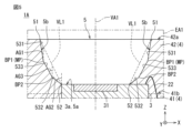
- FIG. 2 is an enlarged cross-sectional view of the EA1 region of the pressure sensor in Figure 2.
- the cut surface is a surface that cuts the recess 5 and includes the imaginary central axis VA1.
- the cut surface may also be a surface that cuts the recess 5 without passing through the imaginary central axis VA1.
- the inner wall surface 5b of the recess 5 has an upper end 51 which is a connection portion with the upper surface 42a of the protrusion 42, and a lower end 52 which is a connection portion with the bottom surface 5a.
- the inner wall surface 5b is recessed outward from an imaginary straight line VL1 which connects the upper end 51 and the lower end 52.
- "outward” means a direction radially away from the imaginary central axis VA1 in a plan view.
- the entire surface of the inner wall surface 5b is recessed outward from the imaginary straight line VL1.
- the inner wall surface 5b is bent at at least one point on the cut surface.
- the inner wall surface 5b is bent at one bending position BP1.
- the bending position BP1 is located at the center MP between the upper end 51 and the lower end 52 of the inner wall surface 5b in the Z direction, or below the center MP.
- the inner wall surface 5b has multiple divisions on the cut surface, separated by the bending position BP1.
- the inner wall surface 5b has an upper division 531 connected to the upper end 51 and a lower division 532 connected to the lower end 52.
- Each of the upper division 531 and the lower division 532 is linear on the cut surface.
- the angle AG2 of the lower division 532 in the Z direction is greater than the angle AG1 of the upper division 531 in the Z direction.
- the angle of the inner wall surface 5b in the Z direction may be simply referred to as the angle of the inner wall surface 5b or the angle of the division.
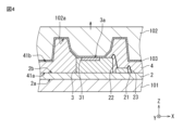
- FIG 4 is a cross-sectional view showing an example of the manufacturing process for the pressure sensor in Figure 2.
- the covering member 4 is formed using two molds: a lower mold 101 and an upper mold 102.
- an aggregate substrate on which a large number of substrates 2 are arranged in the planar direction is placed on the lower mold 101.
- Figure 4 shows a portion of the aggregate substrate that corresponds to one pressure sensor 1.
- the substrate 2 on the lower mold 101 is provided with a detection element 3, a circuit element 21, bonding wires 22, 23, etc.
- the upper die 102 is disposed above the lower die 101 so as to sandwich the substrate 2 between the upper die 102 and the lower die 101.
- the upper die 102 has a lower surface 102a that faces the lower die 101 in the Z direction.
- the lower surface 102a has a shape that corresponds to the shape of the covering member 4.
- a film 103 is provided on the lower surface 102a to prevent the resin that constitutes the covering member 4 from adhering to the upper mold 102.
- the film 103 is sucked toward the lower surface 102a through suction holes (not shown) that open in the lower surface 102a of the upper mold 102.
- the film 103 is a release film that contains Teflon (registered trademark).
- the resin that constitutes the covering member 4 is poured into the space between the substrate 2 and the upper mold 102 (more specifically, the film 103).
- the resin poured into the space hardens to form the covering member 4.
- Figure 4 shows the resin in its hardened state.
- the upper die 102 moves upward along the Z direction as shown by the arrow in FIG. 4.
- the film 103 also moves upward together with the upper die 102 and is peeled off from the hardened coating member 4.
- the inner wall surface 5b of the recess 5 is recessed outward from the imaginary straight line VL1 connecting the upper end 51 and the lower end 52 of the inner wall surface 5b.
- the angle of the inner wall surface 5b can be made larger at the lower part of the inner wall surface 5b (e.g., the lower divided part 532) compared to a configuration in which the inner wall surface 5b is not recessed outward from the imaginary straight line VL1.
- the angle of the upper part of the inner wall surface 5b (e.g., angle AG1 of the upper divided portion 531) is smaller than the angle of the lower part of the inner wall surface 5b (e.g., angle AG2 of the lower divided portion 532) on the cut surface.
- This makes it possible to prevent the opening surface of the recess 5 on the upper surface 42a of the protrusion 42 from becoming larger, compared to a configuration in which the entire surface of the inner wall surface 5b is at the angle of the lower part of the inner wall surface 5b. Therefore, it is possible to prevent the dimensions of the protrusion 42, the covering member 4, and the pressure sensor 1 in the XY directions from becoming larger.
- the dimension in the XY directions between the lower part of the inner wall surface 5b (e.g., lower division part 532) and the outer wall surface 42b of the protrusion 42 (hereinafter also referred to as the "wall thickness of the lower part of the protrusion 42") becomes larger compared to conventional pressure sensors.
- the wall thickness of the lower part of the protrusion 42 increases the mechanical strength of the lower part of the protrusion 42.
- the lower part of the protrusion 42 refers to the part of the protrusion 42 that is located between the lower part of the inner wall surface 5b and the outer wall surface 42b in the direction perpendicular to the Z axis.
- the wall thickness of the lower portion of the protrusion 42 is large, even if the position of the upper die 102 in the XY directions deviates from a predetermined position during the process of forming the coating member 4, the upper die 102 is unlikely to come into contact with the components to be covered by the coating member 4, such as the bonding wires 22 and 23. In other words, the tolerance for positional deviation in the XY directions of the upper die 102 is increased, making it easier to manufacture the pressure sensor 1.
- the inner wall surface 5b is bent at least in one place on the cut surface.
- the upper mold 102 for forming the bent inner wall surface 5b can be made more easily than an upper mold for forming the inner wall surface 5b having a wall surface that is not bent and is smoothly curved. Therefore, the pressure sensor 1 can be manufactured more easily compared to a configuration in which the inner wall surface 5b is not bent.
- the portion of the film 103 located at the bottom of the inner wall surface 5b is located deeper in the recess 5 of the covering member 4 than the portion located at the top of the inner wall surface 5b (see FIG. 4). Therefore, the portion located at the bottom of the inner wall surface 5b is more difficult to peel off from the covering member 4 than the portion located at the top of the inner wall surface 5b.
- the angle of the lower divided portion 532 is larger than the angle of the upper divided portion 531.
- the angle of the inner wall surface 5b is larger in the area of the inner wall surface 5b where the film 103 is particularly difficult to peel off. This further improves the ease with which the film 103 can be peeled off from the covering member 4.
- the lowest bending position BP1 is located at the center MP between the upper end 51 and the lower end 52 of the inner wall surface 5b in the Z direction, or below the center MP.
- the angle of the inner wall surface 5b can be larger in an area of the inner wall surface 5b where the film 103 is particularly difficult to peel off. This further improves the ease of peeling the film 103 from the covering member 4.
- FIG. 5 is a diagram showing the pressure sensor according to the second embodiment of the present disclosure, and is an enlarged cross-sectional view corresponding to the EA1 region in Fig. 2.
- the pressure sensor 1A according to the second embodiment differs from the pressure sensor 1 according to the first embodiment in that the inner wall surface 5b has three or more divisions at the cut surface.
- the same reference symbols are used for configurations similar to those of the pressure sensor 1, and descriptions thereof may be omitted.
- the inner wall surface 5b of the pressure sensor 1A is recessed outward from the imaginary straight line VL1 connecting the upper end 51 and the lower end 52 in the cross section, similar to the pressure sensor 1 according to the first embodiment.
- the inner wall surface 5b is bent at two points: a bending position BP1 and a bending position BP2 that is lower in the Z direction than the bending position BP1.
- the uppermost bending position BP1 on the inner wall surface 5b is located at the center MP between the upper end 51 and the lower end 52 of the inner wall surface 5b in the Z direction, or below the center MP.
- the bending position BP1 is located at the center MP in the Z direction.
- the lowest bending position BP2 on the inner wall surface 5b is located at the center MP between the upper end 51 and the lower end 52 of the inner wall surface 5b in the Z direction, or below the center MP. In this embodiment, the bending position BP2 is located below the center MP in the Z direction.
- the inner wall surface 5b has three divisions on the cut surface, separated by the bending positions BP1 and BP2.
- the portion of the inner wall surface 5b located above the bending position BP1 is the upper division 531 that connects to the upper end portion 51.
- the portion of the inner wall surface 5b located below the bending position BP2 is the lower division 532 that connects to the lower end portion 52.
- the portion of the inner wall surface 5b located between the bending positions BP1 and BP2 is the middle division 533.
- Each of the divisions 531 to 533 is linear on the cut surface.
- the angle of any one of the three or more divisions 531-533 in the Z direction is larger than the angle of each of the divisions located above the selected division in the Z direction. In other words, the angle of each division 531-533 is larger the lower the division 531-533 is located in the Z direction.
- the angle AG2 of the lower division 532 which is the division located at the lowest position, is greater than both the angle AG1 of the upper division 531, which is located above the lower division 532, and the angle AG3 of the middle division 533. Furthermore, the angle AG3 of the middle division 533 is greater than the angle AG1 of the upper division 531, which is located above the middle division 533. In other words, of the angles AG1 to AG3 of the three divisions 531 to 533, the angle AG2 of the lower division 532, which is located at the lowest position, is the largest, and the angle AG1 of the upper division 531, which is located at the highest position, is the smallest.
- the angle of each of the divisions 531-533 is larger for the divisions 531-533 located lower in the Z direction.
- the lower the position on the inner wall surface 5b the smaller the shear resistance with the film 103, making it easier for the film 103 to peel off. Therefore, the film 103 is more easily peeled off from the covering member 4 in the deep part of the recess 5 where it is particularly difficult to peel off.
- Fig. 6 is a diagram showing the pressure sensor according to the third embodiment of the present disclosure, and is an enlarged cross-sectional view corresponding to the EA1 region in Fig. 2.
- the pressure sensor 1B according to the third embodiment differs from the pressure sensor 1 according to the first embodiment in that the inner wall surface 5b is not bent at the cut surface, but instead has a curved portion.
- the same reference symbols are used for configurations similar to those of the pressure sensor 1, and descriptions thereof may be omitted.
- the inner wall surface 5b of the pressure sensor 1B is recessed outward from the imaginary straight line VL1 connecting the upper end 51 and the lower end 52 in the cross section, similar to the pressure sensor 1 according to the first embodiment.
- the inner wall surface 5b has a curved portion 534 that protrudes outward from the imaginary straight line VL1 on the cut surface.
- the curved portion 534 has a curved upper end 534a which is its upper end, and a curved lower end 534b which is its lower end.
- the curved upper end 534a is located below the center MP between the upper end 51 and the lower end 52 of the inner wall surface 5b in the Z direction. Furthermore, the curved upper end 534a is located outward from the imaginary straight line VL1 on the cut surface.
- the curved lower end 534b constitutes the lower end 52 of the inner wall surface 5b on the cut surface.
- the curved portion 534 is connected to the bottom surface 5a of the recess 5.
- the angle of the inner wall surface 5b in the curved portion 534 gradually increases downward.
- the angle of the inner wall surface 5b in the curved portion 534 is, for example, the angle of the tangent at each position of the curved portion 534 relative to the Z direction.
- the inner wall surface 5b except for the curved portion 534, is linear on the cut surface and is connected to the upper end portion 51.
- the inner wall surface 5b has a curved portion 534 that protrudes outward from the imaginary straight line VL1 in the cut surface.
- the angle of the inner wall surface 5b at the curved portion 534 gradually increases the further downward.
- the shear resistance between the curved portion 534 and the film 103 decreases the further downward the position of the inner wall surface 5b, making it easier for the film 103 to peel off.
- the angle of the inner wall surface 5b changes significantly between the upper and lower positions of the bent position.
- the angle of the inner wall surface 5b changes gradually with the position in the Z direction. This further improves the ease of peeling the film 103 from the covering member 4.
- the curved lower end 534b constitutes the lower end 52 of the inner wall surface 5b. Therefore, the lower part of the curved part 534, which has a large angle with respect to the Z direction, is provided at the lower part of the inner wall surface 5b (i.e., the deep part of the recess 5). This further improves the ease of peeling the film 103 from the covering member 4 in the deep part of the recess 5, where the film 103 is particularly difficult to peel off.
- the recess 5 is formed in a rotationally symmetric shape centered on the virtual central axis VA1, but the present disclosure is not limited to this.
- the inner wall surface 5b may be curved only in a partial region in the circumferential direction in a plan view, and may not be curved in the remaining region.
- the entire inner wall surface 5b is recessed outward from the virtual straight line VL1 in the cut surface, but only a portion of the inner wall surface 5b may be recessed outward from the virtual straight line VL1.
- the lowest bending position BP1 is located at the center MP or below the center MP, but it may be located above the center MP.
- the lowest bending position BP2 is located at the center MP or below the center MP, but it may be located above the center MP.
- the inner wall surface 5b is bent at two points on the cut surface, but it may be bent at three or more points.
- the inner wall surface 5b is not curved at the cut surface, but the present disclosure is not limited to this.
- the inner wall surface 5b may be curved in a portion other than the curved portion 534.
- the curved upper end 534a is located below the center MP, but the present disclosure is not limited to this.
- the curved upper end 534a may be located at the center MP, or may be located above the center MP.
- the curved upper end 534a may also constitute the upper end 51 of the inner wall surface 5b. In other words, on the cut surface, the entire surface of the inner wall surface 5b may be the curved portion 534.
- a substrate A detection element provided on an upper surface of the substrate and configured to detect pressure; a covering member provided on an upper surface of the substrate and covering a part of the detection element; Equipped with The covering member is A body provided on an upper surface of the substrate; a protrusion protruding upward from an upper surface of the main body; a recess that is recessed in a vertical direction from an upper surface of the protruding portion and exposes a part of the detection element; having the recess has a tapered shape in which an opening surface becomes smaller as it moves away from the upper surface of the protruding portion in the vertical direction, In a cross section cut along the vertical direction, an inner wall surface of the recess is recessed outward from an imaginary straight line connecting an upper end and a lower end of the inner wall surface.
- a pressure sensor is provided.
- a pressure sensor as described in the first aspect, in which the inner wall surface is bent at least at one location in the cross section.
- the inner wall surface has a plurality of divided portions separated by bending positions, The plurality of divided portions include upper divided portions connected to an upper end portion of the inner wall surface and lower divided portions connected to a lower end portion of the inner wall surface, An angle of the lower divided portion with respect to the vertical direction is larger than an angle of the upper divided portion with respect to the vertical direction.
- a pressure sensor According to a second aspect there is provided a pressure sensor.
- the inner wall surface has three or more of the divided portions, an angle of a division portion selected from the three or more division portions with respect to the vertical direction is greater than an angle of each of the division portions located above the selected division portion with respect to the vertical direction; According to a third aspect there is provided a pressure sensor.
- the inner wall surface is bent at at least one location, The lowest bending position on the inner wall surface is located at the center between the upper end and the lower end of the inner wall surface in the vertical direction, or below the center.
- the present invention provides a pressure sensor according to any one of the second to fourth aspects.
- a pressure sensor according to any one of the first to fifth aspects, in which, in the cross section, the inner wall surface has a curved portion that protrudes outward from the virtual straight line.
- the pressure sensor described in the sixth aspect in which, in the cross section, the lower end of the curved portion constitutes the lower end of the inner wall surface.
- the pressure sensor disclosed herein is useful as a variety of pressure sensors because the film can be easily peeled off from the covering member.
- Reference Signs List 1 1A, 1B Pressure sensor 2 Substrate 2b Top surface 3 Detection element 4 Covering member 41 Body 41b Top surface 42 Protruding portion 42a Top surface 5 Recessed portion 5b Inner wall surface 51 Top end portion 52 Bottom end portion 531 Top divided portion 532 Bottom divided portion 534 Curved portion 534b Curved bottom end portions AG1, AG2 Angle BP1 Bending position MP Center VL1 Virtual straight line
Landscapes
- Physics & Mathematics (AREA)
- General Physics & Mathematics (AREA)
- Chemical & Material Sciences (AREA)
- Analytical Chemistry (AREA)
- Measuring Fluid Pressure (AREA)
Abstract
本開示に係る圧力センサは、基板と、基板の上面に設けられて圧力を検出する検出素子と、基板の上面に設けられて検出素子の一部を覆う被覆部材とを備える。被覆部材は、基板の上面に設けられた本体と、本体の上面から上方へ突出した突出部と、突出部の上面から上下方向に沿って窪み、検出素子の一部を露出させる凹部とを有する。凹部は、上下方向において突出部の上面から離れるに従って開口面が小さくなるテーパ形状を有する。上下方向に沿って切断した断面において、凹部の内壁面は、内壁面の上端部と下端部とを結ぶ仮想直線よりも外方に窪んでいる。
Description
本開示は、MEMS(Micro Electro Mechanical Systems)技術を用いて形成される圧力センサに関する。
従来、この種の圧力センサとしては、例えば、特許文献1に記載のものが知られている。特許文献1に記載された圧力センサは、基板(ベース部材)と、基板上に設けられた検出素子と、基板上に設けられて検出素子を覆う被覆部材(樹脂パッケージ)とを備える。被覆部材は、基板上に設けられた直方体形状の本体部と、基板から離れる方向に本体部の上面から延びた柱状のリング保持部と、リング保持部の頂部から基板に向かって窪み、検出素子の一部を露出させる凹部とを有する。
被覆部材は、例えば、樹脂で構成され、トランスファーモールド法の一種であるFAM(Film Assisted Molding)プロセスによって形成される。当該プロセスでは、基板が載置された下金型と、当該下金型との間に基板を挟むように配置される上金型とが用いられる。基板と上金型との間の空間に樹脂が充填されることによって、基板上に被覆部材が形成される。上金型の下面には、上金型に樹脂が付着するのを防止するために、予めフィルムが設けられる。例えば、当該フィルムは、上金型の下面に設けられた吸引孔を介した吸引によって、当該下面に貼り付けられる。
しかしながら、従来の圧力センサでは、被覆部材の形成後に上金型及びフィルムを被覆部材から取り外すときに、凹部においてフィルムが被覆部材から剥離しにくいという問題があった。
したがって、本開示の目的は、前記課題を解決することにあって、被覆部材からのフィルムの剥離が容易な圧力センサを提供することにある。
本開示に係る圧力センサは、
基板と、
前記基板の上面に設けられ、圧力を検出する検出素子と、
前記基板の上面に設けられ、前記検出素子の一部を覆う被覆部材と、
を備え、
前記被覆部材は、
前記基板の上面に設けられた本体と、
前記本体の上面から上方へ突出した突出部と、
前記突出部の上面から上下方向に沿って窪み、前記検出素子の一部を露出させる凹部と、
を有し、
前記凹部は、上下方向において前記突出部の上面から離れるに従って開口面が小さくなるテーパ形状を有し、
上下方向に沿って切断した断面において、前記凹部の内壁面は、前記内壁面の上端部と下端部とを結ぶ仮想直線よりも外方に窪んでいる。
基板と、
前記基板の上面に設けられ、圧力を検出する検出素子と、
前記基板の上面に設けられ、前記検出素子の一部を覆う被覆部材と、
を備え、
前記被覆部材は、
前記基板の上面に設けられた本体と、
前記本体の上面から上方へ突出した突出部と、
前記突出部の上面から上下方向に沿って窪み、前記検出素子の一部を露出させる凹部と、
を有し、
前記凹部は、上下方向において前記突出部の上面から離れるに従って開口面が小さくなるテーパ形状を有し、
上下方向に沿って切断した断面において、前記凹部の内壁面は、前記内壁面の上端部と下端部とを結ぶ仮想直線よりも外方に窪んでいる。
本開示によれば、被覆部材からのフィルムの剥離が容易な圧力センサを提供することができる。
<本開示の基礎となった知見>
本発明者らは、被覆部材からのフィルムの剥離が容易な圧力センサを提供するために鋭意検討した結果、以下の新たな知見を得た。
本発明者らは、被覆部材からのフィルムの剥離が容易な圧力センサを提供するために鋭意検討した結果、以下の新たな知見を得た。
従来の圧力センサにおいて、凹部は、基板の厚み方向である上下方向においてベース部材に向かうにつれて、開口面が小さくなるテーパ形状を有する。詳しくは、凹部は、検出素子の一部が露出した底面と、リング保持部の頂部と当該底面とを接続する内壁面とを有する。内壁面は、上下方向に沿って延びている。
前述のFAMプロセスにおいて、フィルムは、被覆部材の形成後、上金型と共に上下方向に沿って上方へ移動し、被覆部材から剥がされる。このとき、凹部の内壁面上では、フィルムが上下方向に沿った内壁面の面方向に沿って移動することになり、フィルムと内壁面との間で剪断抵抗が生じる。そのため、フィルムの内壁面上に位置する部分は、上下方向に移動しにくく、被覆部材から剥離しにくい。
そこで、本発明者らは、内壁面の下部に上下方向に対する角度を大きくした部分を設ける構成、すなわち、上下方向に沿った断面において、内壁面が当該内壁面の上端部と下端部とを結ぶ仮想直線よりも外方に窪んだ構成に想到した。内壁面の下部の上下方向に対する角度を大きくすることによって、前記の剪断抵抗が小さくなるので、フィルムは上方に移動しやすくなる。その結果、被覆部材からのフィルムの剥離が容易になる。この新規な知見に基づき、本発明者らは以下の開示に至った。
以下、本開示の実施形態について、図面を参照しながら説明する。なお、以下の説明では、必要に応じて特定の方向又は位置を示す用語(例えば、「上」、「下」、「右」、「左」を含む用語)を用いるが、それらの用語の使用は図面を参照した本開示の理解を容易にするためであって、それらの用語の意味によって本開示の技術的範囲が限定されるものではない。また、以下の説明は、本質的に例示に過ぎず、本開示、その適用物、あるいは、その用途を制限することを意図するものではない。さらに、図面は模式的なものであり、各寸法の比率などは現実のものとは必ずしも合致していない。
本明細書において、「電気的に接続」とは、電流が複数の構成要素の間を導通可能であること、複数の構成要素が容量結合すること、及び複数の構成要素が電磁的に結合することのいずれも含む。
<第1実施形態>
図1及び図2を参照しながら、本開示の第1実施形態に係る圧力センサについて説明する。図1は、本開示の第1実施形態に係る圧力センサの平面図である。図2は、図1の圧力センサのII-II線断面図である。図面には、説明の便宜上、X-Y-Z直交座標系が示されているが、当該座標系は本開示の理解を容易にするためのものであって、本開示を限定するものではない。なお、当該座標系におけるZ方向は、本開示における「上下方向」の一例である。
図1及び図2を参照しながら、本開示の第1実施形態に係る圧力センサについて説明する。図1は、本開示の第1実施形態に係る圧力センサの平面図である。図2は、図1の圧力センサのII-II線断面図である。図面には、説明の便宜上、X-Y-Z直交座標系が示されているが、当該座標系は本開示の理解を容易にするためのものであって、本開示を限定するものではない。なお、当該座標系におけるZ方向は、本開示における「上下方向」の一例である。
図1及び図2に示すように、圧力センサ1は、基板2と、基板2上に設けられた検出素子3と、検出素子3を覆うように基板2上に設けられた被覆部材4とを備える。圧力センサ1によって測定される圧力としては、絶対圧、ゲージ圧、差圧、気流の圧力などがある。
図2に示すように、基板2は、下面2aと、その反対側の上面2bとを有する。例えば、基板2は、樹脂基板などの配線基板、セラミック基板、又はリードフレームである。本実施形態において、基板2は、プリント配線板である。図1に示すように、本実施形態において、基板2は、Z方向から見た平面視において、X方向又はY方向に延びた辺を有する正方形である。
図1及び図2に示すように、基板2の上面2bには、検出素子3と回路素子21とが配置されている。検出素子3は、圧力を検出する圧力センサ素子である。例えば、検出素子3は、ピエゾ抵抗型又は静電容量型の圧力センサ素子であり、MEMS(Micro Electro Mechanical Systems)素子である。本実施形態において、検出素子3は、直方体に形成され、基板2の上面2bを向く面と反対側の上面3aを有する。検出素子3は、上面3aに設けられ、圧力が作用する検出部31を有する。例えば、検出部31は、圧力を受けるメンブレンやダイヤフラムである。
例えば、回路素子21は、特定用途向け集積回路(ASIC:Application Specific Integrated Circuit)を備える素子である。本実施形態において、回路素子21は、検出素子3から出力された電圧信号をデジタル信号に変換するコンバータ、コンバータからのデジタル信号をフィルタリングするフィルタ、温度を検出する温度センサ、温度センサの検出温度に基づいてフィルタリングされたデジタル信号を補正するプロセッサ、検出温度を用いてデジタル信号を補正するときに使用する補正係数などを記憶するメモリなどを備える。
本実施形態において、検出素子3と回路素子21とは、図2に示すように、基板2の上面2bにおいてX方向に並んで配置されている。例えば、検出素子3及び回路素子21の各々は、ダイアタッチフィルム、ダイボンド材などの接着部材を介して、基板2に接合されている。
本実施形態において、検出素子3と回路素子21とは、検出素子3の上面3aから延びたボンディングワイヤ22を介して接続されている。また、回路素子21と、基板2とは、回路素子21の表面から延びたボンディングワイヤ23を介して接続されている。これにより、基板2に設けられた回路と、検出素子3と、回路素子21とは、電気的に接続されている。
なお、検出素子3と回路素子21とは、基板2の回路を介して電気的に接続されてもよい。例えば、検出素子3及び回路素子21の各々は、ボンディングワイヤやバンプを介して、基板2の回路に接続されてもよい。また、検出素子3と回路素子21とは、基板2上でZ方向に重ねて配置されてもよい。
被覆部材4は、基板2の上面2bに設けられ、検出素子3の一部、回路素子21、及びボンディングワイヤ22,23を覆っている。被覆部材4は、基板2の上面2bに設けられた本体41と、当該本体41からZ方向に沿って上方へ突出した突出部42とを有する。本体41は、基板2を向く下面41a及びその反対側の上面41bを有する。突出部42は、本体41の上面41bから突出している。本実施形態において、被覆部材4は、樹脂で構成されている。本体41と突出部42とは、一体成形されている。図2及び後述の図3~6には、本体41と突出部42との境界が破線で示されている。
例えば、本体41及び突出部42の各々は、平面視において、円形、楕円形、又は多角形である。
図1及び図2に示すように、本体41は、本実施形態において直方体であり、基板2の上面2bの全面に設けられている。
突出部42は、Z方向に沿って上方へ向かうにつれて細くなる円錐台形状を有する。突出部42は、頂面である上面42aと、当該上面42aと本体41の上面41bとを接続する外壁面42bとを有する。
図1及び図2に示すように、本体41の上面41bには、平面視において突出部42を囲むようにOリング6が設けられてもよい。例えば、Oリング6は、ゴム、シリコンなどの弾性部材で構成されている。Oリング6は、引き伸ばされた状態で突出部42の周囲に設けられ、突出部42の外壁面42bに接触してもよい。この場合、Oリング6は、圧力センサ1が電子機器に取り付けられたときに、当該電子部品の筐体と圧力センサ1との間で潰されて弾性変形し、これらの間に水分が流れ込むのを抑制してもよい。
被覆部材4には、突出部42の上面42aからZ方向に沿って下方へ窪み、検出素子3の一部を露出させる凹部5が設けられている。例えば、凹部5は、検出素子3の検出部31を露出させている。つまり、被覆部材4は、凹部5を除く部分で検出素子3を覆っている。
図2に示すように、凹部5は、本実施形態において、Z方向において突出部42の上面42aから離れるに従って開口面が小さくなるテーパ形状を有する。本実施形態において、凹部5は、Z方向に沿って延びた仮想中心軸VA1を中心とした回転対称形状に形成されている。凹部5の開口面の形状は、平面視において角部が丸められた略矩形である。
凹部5は、検出素子3が露出した底面5aと、当該底面5aと突出部42の上面42aとを接続する内壁面5bとを有する。底面5aは、その全面が検出素子3の上面3aによって構成されてもよく、図1に示すように、一部のみが当該上面3aによって構成され、残部が被覆部材4の表面として構成されてもよい。
図2及び図3に示す、Z方向に沿って切断した断面(以下「切断面」ともいう。)を参照して、凹部5の内壁面5bの形状について説明する。図3は、図2の圧力センサのEA1領域の拡大断面図である。本実施形態において、切断面は、凹部5を切断する面であって仮想中心軸VA1を含む面である。切断面は、仮想中心軸VA1を通らずに凹部5を切断する面であってもよい。
図3に示すように、切断面において、凹部5の内壁面5bは、突出部42の上面42aとの接続部である上端部51と、底面5aとの接続部である下端部52とを有する。内壁面5bは、上端部51と下端部52とを結ぶ仮想直線VL1よりも外方に窪んでいる。ここで「外方」とは、平面視において仮想中心軸VA1から放射方向に離れる方向である。本実施形態においては、切断面において、内壁面5bの全面が仮想直線VL1よりも外方に窪んでいる。
内壁面5bは、切断面において、少なくとも1箇所で屈曲している。第1実施形態において、内壁面5bは、1箇所の屈曲位置BP1において屈曲している。第1実施形態において、屈曲位置BP1は、Z方向における内壁面5bの上端部51と下端部52との中央MP、又は当該中央MPよりも下方に位置している。
内壁面5bは、切断面において、屈曲位置BP1を境界として区切られた複数の分割部を有する。本実施形態において、内壁面5bは、上端部51に接続する上分割部531と、下端部52に接続する下分割部532とを有する。上分割部531及び下分割部532の各々は、切断面において直線状である。
切断面において、下分割部532のZ方向に対する角度AG2は、上分割部531のZ方向に対する角度AG1よりも大きい。なお、以下の説明では、内壁面5bのZ方向に対する角度のことを、単に内壁面5bの角度又は分割部の角度ということがある。
図4を参照しながら、圧力センサ1における被覆部材4の形成方法の一例であるFAMプロセスについて説明する。図4は、図2の圧力センサの製造工程の一例を示す断面図である。
当該プロセスにおいて、被覆部材4は、下金型101と上金型102との2つの金型を用いて形成される。被覆部材4の形成工程において、下金型101上には、多数の基板2が面方向に並んだ集合基板が配置されている。図4には、当該集合基板のうち、1つの圧力センサ1に対応する部分が示されている。下金型101上の基板2は、検出素子3、回路素子21、ボンディングワイヤ22,23などが設けられた状態である。
上金型102は、基板2を下金型101との間に挟むように、下金型101の上方に配置される。上金型102は、Z方向において下金型101に対向する下面102aを有する。下面102aは、被覆部材4の形状に対応した形状を有する。
下面102a上には、被覆部材4を構成する樹脂が上金型102に付着するのを防止するフィルム103が設けられている。フィルム103は、上金型102の下面102aに開口した吸引孔(図示せず)を介して、下面102aに向かって吸引されている。例えば、フィルム103は、テフロン(登録商標)を含む離型フィルムである。
被覆部材4を構成する樹脂は、基板2と上金型102(詳しくは、フィルム103)との間の空間に流し込まれる。当該空間に流し込まれた樹脂が硬化することによって、被覆部材4が形成される。図4には、当該樹脂が硬化した状態が示されている。
次いで、上金型102は、図4に矢印で示すように、Z方向に沿って上方へ移動する。このとき、フィルム103も上金型102と共に上方へ移動し、硬化した被覆部材4から剥がされる。
第1実施形態に係る圧力センサ1によれば、切断面において、凹部5の内壁面5bは、内壁面5bの上端部51と下端部52とを結ぶ仮想直線VL1よりも外方に窪んでいる。この構成によれば、内壁面5bが仮想直線VL1よりも外方に窪んでいない構成と比較して、内壁面5bの下部(例えば、下分割部532)において、内壁面5bの角度を大きくすることができる。これにより、内壁面5bの下部において、内壁面5bとフィルム103との間に生じる剪断抵抗が小さくなるので、フィルム103が被覆部材4から剥離しやすくなる。したがって、被覆部材4からのフィルム103の剥離が容易な圧力センサ1を提供することができる。
また、内壁面5bが仮想直線VL1よりも外方に窪んでいるので、切断面において、内壁面5bの上部の角度(例えば、上分割部531の角度AG1)は、内壁面5bの下部の角度(例えば、下分割部532の角度AG2)よりも小さくなる。これにより、内壁面5bの全面が内壁面5bの下部の角度である構成と比較して、突出部42の上面42aにおける凹部5の開口面が大きくなるのを抑制することができる。したがって、突出部42、被覆部材4、及び圧力センサ1のXY方向における寸法が大きくなるのを抑制することができる。
また、内壁面5bの下部の角度が大きくなることによって、従来の圧力センサと比較して、内壁面5bの下部(例えば、下分割部532)と突出部42の外壁面42bとの間のXY方向における寸法(以下「突出部42の下部の壁厚」ともいう。)が大きくなる。これにより、突出部42の下部の機械的強度が高まる。ここで、突出部42の下部とは、Z軸に対する直交方向において、突出部42のうち、内壁面5bの下部と外壁面42bとの間に位置する部分をいう。
突出部42の下部の機械的強度が高まることによって、Oリング6からその弾性によって外壁面42bにかかる圧力に対する突出部42の耐久性が向上する。また、外部から突出部42に加わった衝撃が検出素子3に伝わりにくくなるので、検出素子3によって検出される圧力の正確性が向上する。
また、突出部42の下部の壁厚が大きいので、被覆部材4の形成工程において、上金型102のXY方向における位置が所定の位置からずれた場合にも、上金型102は、ボンディングワイヤ22,23などの被覆部材4によって被覆されるべき部材と接触しにくい。換言すれば、上金型102のXY方向における位置ずれの許容量が大きくなるので、圧力センサ1の製造が容易になる。
また、第1実施形態に係る圧力センサ1によれば、切断面において、内壁面5bは、少なくとも1箇所において屈曲している。屈曲した内壁面5bを形成するための上金型102は、屈曲せずに滑らかに湾曲する壁面を有する内壁面5bを形成するための上金型よりも容易に作製することができる。そのため、内壁面5bが屈曲していない構成と比較して、圧力センサ1の製造が容易になる。
フィルム103のうち、内壁面5bの下部に位置する部分は、内壁面5bの上部に位置する部分と比較して、被覆部材4の凹部5に深く入り込んだ部分に位置する(図4参照)。そのため、当該内壁面5bの下部に位置する部分は、内壁面5bの上部に位置する部分よりも被覆部材4から一層剥離しにくい。
第1実施形態に係る圧力センサ1によれば、下分割部532の角度が上分割部531の角度よりも大きい。つまり、内壁面5bのうち、フィルム103が特に剥離しにくい領域において、内壁面5bの角度が大きくなっている。したがって、被覆部材4からのフィルム103の剥離しやすさが一層向上する。
また、第1実施形態に係る圧力センサ1によれば、最も下方にある屈曲位置BP1は、Z方向における内壁面5bの上端部51と下端部52との中央MP、又は中央MPよりも下方に位置している。これにより、当該屈曲位置BP1が中央MPよりも上方に位置する構成と比較して、当該屈曲位置BP1よりも下方の分割部(例えば、下分割部532)の角度を大きくすることができる。つまり、内壁面5bのうち、フィルム103が特に剥離しにくい領域において、内壁面5bの角度が大きくすることができる。したがって、被覆部材4からのフィルム103の剥離しやすさが一層向上する。
<第2実施形態>
図5を参照しながら、本開示の第2実施形態に係る圧力センサについて説明する。図5は、本開示の第2実施形態に係る圧力センサを示す図であり、図2におけるEA1領域に対応する拡大断面図である。
図5を参照しながら、本開示の第2実施形態に係る圧力センサについて説明する。図5は、本開示の第2実施形態に係る圧力センサを示す図であり、図2におけるEA1領域に対応する拡大断面図である。
第2実施形態に係る圧力センサ1Aは、内壁面5bが切断面において3つ以上の分割部を有する点で、第1実施形態に係る圧力センサ1と異なっている。なお、以下の第2実施形態の説明では、圧力センサ1と同様の構成については、同一の参照符号を付して説明を省略することがある。
図5に示すように、圧力センサ1Aにおける内壁面5bは、切断面において、第1実施形態に係る圧力センサ1と同様に、上端部51と下端部52とを結ぶ仮想直線VL1よりも外方に窪んでいる。内壁面5bは、屈曲位置BP1と、当該屈曲位置BP1よりもZ方向において下方にある屈曲位置BP2との2箇所において屈曲している。
例えば、内壁面5bにおいて最も上方にある屈曲位置BP1は、Z方向における内壁面5bの上端部51と下端部52との中央MP、又は中央MPよりも下方に位置している。本実施形態において、屈曲位置BP1は、Z方向における中央MPに位置している。
内壁面5bにおいて最も下方にある屈曲位置BP2は、Z方向における内壁面5bの上端部51と下端部52との中央MP、又は中央MPよりも下方に位置している。本実施形態において、屈曲位置BP2は、Z方向における中央MPよりも下方に位置している。
内壁面5bは、切断面において、各屈曲位置BP1,BP2を境界として区切られた3つの分割部を有する。内壁面5bのうち、屈曲位置BP1よりも上方に位置する部分は、上端部51に接続する上分割部531である。内壁面5bのうち、屈曲位置BP2よりも下方に位置する部分は、下端部52に接続する下分割部532である。内壁面5bのうち、屈曲位置BP1と屈曲位置BP2との間に位置する部分は、中分割部533である。各分割部531~533は、切断面において直線状である。
切断面において、3つ以上の分割部531~533から任意に選択される分割部のZ方向に対する角度は、当該分割部よりも上方に位置する分割部の各々のZ方向に対する角度よりも大きい。換言すれば、各分割部531~533の角度は、Z方向において下方に位置する分割部531~533ほど大きくなっている。
具体的には、最も下方に位置する分割部である下分割部532の角度AG2は、当該下分割部532よりも上方に位置する上分割部531の角度AG1及び中分割部533の角度AG3の両方よりも大きい。また、中分割部533の角度AG3は、当該中分割部533よりも上方に位置する上分割部531の角度AG1よりも大きい。つまり、3つの分割部531~533の角度AG1~AG3において、最も下方に位置する下分割部532の角度AG2が最大であり、最も上方に位置する上分割部531の角度AG1が最小である。
第2実施形態に係る圧力センサ1Aによれば、各分割部531~533の角度は、Z方向において下方に位置する分割部531~533ほど大きくなっている。この構成によれば、内壁面5bのより下方の位置ほど、フィルム103との剪断抵抗が小さくなり、フィルム103が剥離しやすくなる。そのため、フィルム103が特に剥離しにくい凹部5の深部において、被覆部材4からのフィルム103の剥離しやすさが一層向上する。
<第3実施形態>
図6を参照しながら、本開示の第3実施形態に係る圧力センサについて説明する。図6は、本開示の第3実施形態に係る圧力センサを示す図であり、図2におけるEA1領域に対応する拡大断面図である。
図6を参照しながら、本開示の第3実施形態に係る圧力センサについて説明する。図6は、本開示の第3実施形態に係る圧力センサを示す図であり、図2におけるEA1領域に対応する拡大断面図である。
第3実施形態に係る圧力センサ1Bは、内壁面5bが切断面において屈曲しておらず、代わりに湾曲した部分を有する点で、第1実施形態に係る圧力センサ1と異なっている。なお、以下の第3実施形態の説明では、圧力センサ1と同様の構成については、同一の参照符号を付して説明を省略することがある。
図6に示すように、圧力センサ1Bにおける内壁面5bは、切断面において、第1実施形態に係る圧力センサ1と同様に、上端部51と下端部52とを結ぶ仮想直線VL1よりも外方に窪んでいる。
内壁面5bは、切断面において、仮想直線VL1よりも外方に突出した湾曲部534を有する。湾曲部534は、その上端部である湾曲上端部534aと、下端部である湾曲下端部534bとを有する。本実施形態において、湾曲上端部534aは、Z方向における内壁面5bの上端部51と下端部52との中央MPよりも下方に位置している。また、湾曲上端部534aは、切断面において、仮想直線VL1よりも外方に位置している。
湾曲下端部534bは、切断面において、内壁面5bの下端部52を構成している。すなわち、湾曲部534は、凹部5の底面5aに接続している。
湾曲部534における内壁面5bの角度は、下方に向かうにつれて漸次的に大きくなっている。ここで、湾曲部534における内壁面5bの角度とは、例えば、湾曲部534の各位置における接線のZ方向に対する角度である。
本実施形態において、内壁面5bの湾曲部534を除く部分は、切断面において直線状であり、上端部51に接続している。
第3実施形態に係る圧力センサ1Bによれば、内壁面5bは、切断面において仮想直線VL1よりも外方に突出した湾曲部534を有する。湾曲部534における内壁面5bの角度は、下方に向かうにつれて漸次的に大きくなっている。これにより、湾曲部534において、内壁面5bのより下方の位置ほど、フィルム103との剪断抵抗が小さくなり、フィルム103が剥離しやすくなる。
また、第1及び第2実施形態に係る圧力センサ1,1Aのように、屈曲した内壁面5bでは、屈曲位置の上方の位置と下方の位置との間で、内壁面5bの角度が大きく変化する。他方で、圧力センサ1Bの湾曲部534においては、内壁面5bの角度は、Z方向における位置とともに漸次的に変化している。そのため、被覆部材4からのフィルム103の剥離しやすさが一層向上する。
また、第3実施形態に係る圧力センサ1Bによれば、湾曲下端部534bは、内壁面5bの下端部52を構成している。そのため、Z方向に対する角度の大きい湾曲部534の下部は、内壁面5bの下部(すなわち、凹部5の深部)に設けられる。これにより、フィルム103が特に剥離しにくい凹部5の深部において、被覆部材4からのフィルム103の剥離しやすさが一層向上する。
なお、本開示は、前記実施形態に限定されるものではなく、その他種々の態様で実施することができる。例えば、前記実施形態では、凹部5が仮想中心軸VA1を中心とした回転対称形状に形成されているものとしたが、本開示はこれに限定されない。例えば、内壁面5bは、平面視での周方向における一部の領域のみにおいて屈曲し、残りの領域では屈曲していなくてもよい。
また、前記実施形態では、切断面において、内壁面5bの全面が仮想直線VL1よりも外方に窪んでいるものとしたが、内壁面5bの一部のみが仮想直線VL1よりも外方に窪んでいてもよい。
また、前記第1実施形態では、最も下方にある屈曲位置BP1が中央MP又は中央MPよりも下方に位置するものとしたが、中央MPよりも上方にあってもよい。また、前記第2実施形態では、最も下方にある屈曲位置BP2が中央MP又は中央MPよりも下方に位置するものとしたが、中央MPよりも上方にあってもよい。
また、前記第2実施形態において、内壁面5bが切断面において2箇所で屈曲しているものとしたが、3箇所以上で屈曲していてもよい。
また、前記第3実施形態では、切断面において、内壁面5bが屈曲していないものとしたが、本開示はこれに限定されない。例えば、内壁面5bは、湾曲部534を除く部分において屈曲していてもよい。
また、前記第3実施形態では、湾曲上端部534aが中央MPよりも下方に位置するものとしたが、本開示はこれに限定されない。例えば、湾曲上端部534aは、中央MPに位置してもよく、中央MPよりも上方に位置してもよい。また、湾曲上端部534aは、内壁面5bの上端部51を構成してもよい。つまり、切断面において、内壁面5bの全面が湾曲部534であってもよい。
前記様々な実施形態又は変形例のうちの任意の実施形態又は変形例を適宜組み合わせることによって、それぞれの有する効果を奏するようにすることができる。また、実施形態同士の組み合わせ、実施例同士の組み合わせ、又は実施形態と実施例との組み合わせが可能であると共に、異なる実施形態又は実施例の中の特徴同士の組み合わせも可能である。
本開示は、添付図面を参照しながら好ましい実施形態に関連して充分に記載されているが、この技術の熟練した人々にとっては種々の変形や修正は明白である。そのような変形や修正は、添付した請求の範囲による本開示の範囲から外れない限りにおいて、その中に含まれると理解されるべきである。
以上、図面を参照して本開示における種々の実施形態を詳細に説明したが、最後に、本開示の種々の態様について説明する。
本開示の第1態様によれば、
基板と、
前記基板の上面に設けられ、圧力を検出する検出素子と、
前記基板の上面に設けられ、前記検出素子の一部を覆う被覆部材と、
を備え、
前記被覆部材は、
前記基板の上面に設けられた本体と、
前記本体の上面から上方へ突出した突出部と、
前記突出部の上面から上下方向に沿って窪み、前記検出素子の一部を露出させる凹部と、
を有し、
前記凹部は、上下方向において前記突出部の上面から離れるに従って開口面が小さくなるテーパ形状を有し、
上下方向に沿って切断した断面において、前記凹部の内壁面は、前記内壁面の上端部と下端部とを結ぶ仮想直線よりも外方に窪んでいる、
圧力センサを提供する。
基板と、
前記基板の上面に設けられ、圧力を検出する検出素子と、
前記基板の上面に設けられ、前記検出素子の一部を覆う被覆部材と、
を備え、
前記被覆部材は、
前記基板の上面に設けられた本体と、
前記本体の上面から上方へ突出した突出部と、
前記突出部の上面から上下方向に沿って窪み、前記検出素子の一部を露出させる凹部と、
を有し、
前記凹部は、上下方向において前記突出部の上面から離れるに従って開口面が小さくなるテーパ形状を有し、
上下方向に沿って切断した断面において、前記凹部の内壁面は、前記内壁面の上端部と下端部とを結ぶ仮想直線よりも外方に窪んでいる、
圧力センサを提供する。
本開示の第2態様によれば、前記断面において、前記内壁面は、少なくとも1箇所で屈曲している、第1態様に記載の圧力センサを提供する。
本開示の第3態様によれば、
前記断面において、
前記内壁面は、屈曲位置を境界として区切られた複数の分割部を有し、
複数の前記分割部は、前記内壁面の上端部に接続する上分割部と、前記内壁面の下端部に接続する下分割部とを有し、
前記下分割部の上下方向に対する角度は、前記上分割部の上下方向に対する角度よりも大きい、
第2態様に記載の圧力センサを提供する。
前記断面において、
前記内壁面は、屈曲位置を境界として区切られた複数の分割部を有し、
複数の前記分割部は、前記内壁面の上端部に接続する上分割部と、前記内壁面の下端部に接続する下分割部とを有し、
前記下分割部の上下方向に対する角度は、前記上分割部の上下方向に対する角度よりも大きい、
第2態様に記載の圧力センサを提供する。
本開示の第4態様によれば、
前記断面において、
前記内壁面は、3つ以上の前記分割部を有し、
3つ以上の前記分割部から任意に選択される前記分割部の上下方向に対する角度は、当該分割部よりも上方に位置する前記分割部の各々の上下方向に対する角度よりも大きい、
第3態様に記載の圧力センサを提供する。
前記断面において、
前記内壁面は、3つ以上の前記分割部を有し、
3つ以上の前記分割部から任意に選択される前記分割部の上下方向に対する角度は、当該分割部よりも上方に位置する前記分割部の各々の上下方向に対する角度よりも大きい、
第3態様に記載の圧力センサを提供する。
本開示の第5態様によれば、
前記断面において、
前記内壁面は、少なくとも1箇所で屈曲し、
前記内壁面において最も下方にある屈曲位置は、上下方向における前記内壁面の上端部と下端部との中央、又は前記中央よりも下方に位置している、
第2~第4態様のいずれか1つに記載の圧力センサを提供する。
前記断面において、
前記内壁面は、少なくとも1箇所で屈曲し、
前記内壁面において最も下方にある屈曲位置は、上下方向における前記内壁面の上端部と下端部との中央、又は前記中央よりも下方に位置している、
第2~第4態様のいずれか1つに記載の圧力センサを提供する。
本開示の第6態様によれば、前記断面において、前記内壁面は、前記仮想直線よりも外方に突出した湾曲部を有する、第1~第5態様のいずれか1つに記載の圧力センサを提供する。
本開示の第7態様によれば、前記断面において、前記湾曲部の下端部は、前記内壁面の下端部を構成している、第6態様に記載の圧力センサを提供する。
本開示に係る圧力センサは、被覆部材からのフィルムの剥離が容易なので、種々の圧力センサとして有用である。
1,1A,1B 圧力センサ
2 基板
2b 上面
3 検出素子
4 被覆部材
41 本体
41b 上面
42 突出部
42a 上面
5 凹部
5b 内壁面
51 上端部
52 下端部
531 上分割部
532 下分割部
534 湾曲部
534b 湾曲下端部
AG1,AG2 角度
BP1 屈曲位置
MP 中央
VL1 仮想直線
2 基板
2b 上面
3 検出素子
4 被覆部材
41 本体
41b 上面
42 突出部
42a 上面
5 凹部
5b 内壁面
51 上端部
52 下端部
531 上分割部
532 下分割部
534 湾曲部
534b 湾曲下端部
AG1,AG2 角度
BP1 屈曲位置
MP 中央
VL1 仮想直線
Claims (7)
- 基板と、
前記基板の上面に設けられ、圧力を検出する検出素子と、
前記基板の上面に設けられ、前記検出素子の一部を覆う被覆部材と、
を備え、
前記被覆部材は、
前記基板の上面に設けられた本体と、
前記本体の上面から上方へ突出した突出部と、
前記突出部の上面から上下方向に沿って窪み、前記検出素子の一部を露出させる凹部と、
を有し、
前記凹部は、上下方向において前記突出部の上面から離れるに従って開口面が小さくなるテーパ形状を有し、
上下方向に沿って切断した断面において、前記凹部の内壁面は、前記内壁面の上端部と下端部とを結ぶ仮想直線よりも外方に窪んでいる、
圧力センサ。 - 前記断面において、前記内壁面は、少なくとも1箇所で屈曲している、請求項1に記載の圧力センサ。
- 前記断面において、
前記内壁面は、屈曲位置を境界として区切られた複数の分割部を有し、
複数の前記分割部は、前記内壁面の上端部に接続する上分割部と、前記内壁面の下端部に接続する下分割部とを有し、
前記下分割部の上下方向に対する角度は、前記上分割部の上下方向に対する角度よりも大きい、
請求項2に記載の圧力センサ。 - 前記断面において、
前記内壁面は、3つ以上の前記分割部を有し、
3つ以上の前記分割部から任意に選択される前記分割部の上下方向に対する角度は、当該分割部よりも上方に位置する前記分割部の各々の上下方向に対する角度よりも大きい、
請求項3に記載の圧力センサ。 - 前記断面において、
前記内壁面は、少なくとも1箇所で屈曲し、
前記内壁面において最も下方にある屈曲位置は、上下方向における前記内壁面の上端部と下端部との中央、又は前記中央よりも下方に位置している、
請求項2~4のいずれか1つに記載の圧力センサ。 - 前記断面において、前記内壁面は、前記仮想直線よりも外方に突出した湾曲部を有する、請求項1~5のいずれか1つに記載の圧力センサ。
- 前記断面において、前記湾曲部の下端部は、前記内壁面の下端部を構成している、請求項6に記載の圧力センサ。
Priority Applications (2)
| Application Number | Priority Date | Filing Date | Title |
|---|---|---|---|
| CN202480034172.2A CN121175546A (zh) | 2023-06-14 | 2024-05-14 | 压力传感器 |
| US19/377,177 US20260056074A1 (en) | 2023-06-14 | 2025-11-03 | Pressure sensor |
Applications Claiming Priority (2)
| Application Number | Priority Date | Filing Date | Title |
|---|---|---|---|
| JP2023097641 | 2023-06-14 | ||
| JP2023-097641 | 2023-06-14 |
Related Child Applications (1)
| Application Number | Title | Priority Date | Filing Date |
|---|---|---|---|
| US19/377,177 Continuation US20260056074A1 (en) | 2023-06-14 | 2025-11-03 | Pressure sensor |
Publications (1)
| Publication Number | Publication Date |
|---|---|
| WO2024257532A1 true WO2024257532A1 (ja) | 2024-12-19 |
Family
ID=93852058
Family Applications (1)
| Application Number | Title | Priority Date | Filing Date |
|---|---|---|---|
| PCT/JP2024/017760 Ceased WO2024257532A1 (ja) | 2023-06-14 | 2024-05-14 | 圧力センサ |
Country Status (3)
| Country | Link |
|---|---|
| US (1) | US20260056074A1 (ja) |
| CN (1) | CN121175546A (ja) |
| WO (1) | WO2024257532A1 (ja) |
Citations (5)
| Publication number | Priority date | Publication date | Assignee | Title |
|---|---|---|---|---|
| JP2003086724A (ja) * | 2001-09-07 | 2003-03-20 | Sharp Corp | 半導体装置および指紋検知装置 |
| JP2010021225A (ja) * | 2008-07-09 | 2010-01-28 | Sharp Corp | 電子部品およびその製造方法、並びに、電子部品を備えた電子装置 |
| WO2019208127A1 (ja) * | 2018-04-25 | 2019-10-31 | 株式会社村田製作所 | 半導体装置及び電子機器 |
| WO2022102234A1 (ja) * | 2020-11-16 | 2022-05-19 | 株式会社村田製作所 | 半導体装置及び電子機器 |
| WO2023032501A1 (ja) * | 2021-08-31 | 2023-03-09 | 株式会社村田製作所 | 圧力センサ素子及び圧力センサ |
-
2024
- 2024-05-14 WO PCT/JP2024/017760 patent/WO2024257532A1/ja not_active Ceased
- 2024-05-14 CN CN202480034172.2A patent/CN121175546A/zh active Pending
-
2025
- 2025-11-03 US US19/377,177 patent/US20260056074A1/en active Pending
Patent Citations (5)
| Publication number | Priority date | Publication date | Assignee | Title |
|---|---|---|---|---|
| JP2003086724A (ja) * | 2001-09-07 | 2003-03-20 | Sharp Corp | 半導体装置および指紋検知装置 |
| JP2010021225A (ja) * | 2008-07-09 | 2010-01-28 | Sharp Corp | 電子部品およびその製造方法、並びに、電子部品を備えた電子装置 |
| WO2019208127A1 (ja) * | 2018-04-25 | 2019-10-31 | 株式会社村田製作所 | 半導体装置及び電子機器 |
| WO2022102234A1 (ja) * | 2020-11-16 | 2022-05-19 | 株式会社村田製作所 | 半導体装置及び電子機器 |
| WO2023032501A1 (ja) * | 2021-08-31 | 2023-03-09 | 株式会社村田製作所 | 圧力センサ素子及び圧力センサ |
Also Published As
| Publication number | Publication date |
|---|---|
| CN121175546A (zh) | 2025-12-19 |
| US20260056074A1 (en) | 2026-02-26 |
Similar Documents
| Publication | Publication Date | Title |
|---|---|---|
| US8316725B2 (en) | Force sensor | |
| JP4740678B2 (ja) | 半導体装置 | |
| US8375799B2 (en) | Increased sensor die adhesion | |
| US8590389B2 (en) | MEMS pressure sensor device and manufacturing method thereof | |
| US20130247689A1 (en) | Force sensor | |
| EP2474820A2 (en) | Pressure sensor with low cost packaging | |
| US20170241852A1 (en) | Flip chip pressure sensor assembly | |
| US20150068315A1 (en) | Media isolated pressure sensor | |
| US7469590B2 (en) | Package structure of pressure sensor | |
| WO2021049138A1 (ja) | 半導体装置およびその製造方法 | |
| JP6258977B2 (ja) | センサおよびその製造方法 | |
| JP2011180146A (ja) | 半導体装置 | |
| CN113264497A (zh) | Mems芯片的封装结构 | |
| US9963339B2 (en) | Sensor device | |
| CN121175546A (zh) | 压力传感器 | |
| EP3273213A2 (en) | Low cost overmolded leadframe force sensor with multiple mounting positions | |
| WO2025154433A1 (ja) | 圧力センサ | |
| CN105304581B (zh) | 压力检测装置 | |
| WO2022239442A1 (ja) | 差圧センサ及びその製造方法 | |
| WO2018074094A1 (ja) | 圧力センサ | |
| WO2024219096A1 (ja) | 圧力センサ及び電子機器 | |
| US20250282610A1 (en) | Semiconductor device and method for manufacturing the same | |
| EP4530593A1 (en) | Pressure sensor with flange | |
| JP2018185215A (ja) | センサ | |
| CN121889333A (zh) | 传感器电子装置 |
Legal Events
| Date | Code | Title | Description |
|---|---|---|---|
| 121 | Ep: the epo has been informed by wipo that ep was designated in this application |
Ref document number: 24823154 Country of ref document: EP Kind code of ref document: A1 |
|
| WWE | Wipo information: entry into national phase |
Ref document number: CN2024800341722 Country of ref document: CN |
|
| NENP | Non-entry into the national phase |
Ref country code: DE |