WO2024257518A1 - 衝突防止制御システム及び方法 - Google Patents
衝突防止制御システム及び方法 Download PDFInfo
- Publication number
- WO2024257518A1 WO2024257518A1 PCT/JP2024/017361 JP2024017361W WO2024257518A1 WO 2024257518 A1 WO2024257518 A1 WO 2024257518A1 JP 2024017361 W JP2024017361 W JP 2024017361W WO 2024257518 A1 WO2024257518 A1 WO 2024257518A1
- Authority
- WO
- WIPO (PCT)
- Prior art keywords
- slider
- controller
- module
- collision prevention
- prevention control
- Prior art date
- Legal status (The legal status is an assumption and is not a legal conclusion. Google has not performed a legal analysis and makes no representation as to the accuracy of the status listed.)
- Pending
Links
Images


Classifications
-
- H—ELECTRICITY
- H02—GENERATION; CONVERSION OR DISTRIBUTION OF ELECTRIC POWER
- H02P—CONTROL OR REGULATION OF ELECTRIC MOTORS, ELECTRIC GENERATORS OR DYNAMO-ELECTRIC CONVERTERS; CONTROLLING TRANSFORMERS, REACTORS OR CHOKE COILS
- H02P25/00—Arrangements or methods for the control of AC motors characterised by the kind of AC motor or by structural details
- H02P25/02—Arrangements or methods for the control of AC motors characterised by the kind of AC motor or by structural details characterised by the kind of motor
- H02P25/06—Linear motors
- H02P25/064—Linear motors of the synchronous type
Definitions
- the present invention relates to a collision prevention control system and method used in a conveying device in which multiple sliders move along a conveying path having multiple modules.
- a transport device has been developed in which multiple sliders move along a transport path.
- the transport path is made up of a combination of multiple modules.
- the module is equipped with multiple coils that serve as the stators of the linear motor, and a drive circuit that controls the power supplied to the multiple coils.
- the slider is equipped with a permanent magnet that serves as the mover of the linear motor. When the power supplied to the multiple coils is controlled by the drive circuit and a moving magnetic field is generated in the multiple coils, the slider moves along the transport path.
- This type of conveying device has the advantage of being more flexible than conventional belt conveyors. For example, unlike conventional belt conveyors, there is no need to move multiple sliders all at once; instead, multiple sliders can be moved and positioned individually. Also, by rearranging the modules as appropriate, an appropriate conveying path can be created depending on the application. For this reason, this type of conveying device is used for a variety of applications (manufacturing, processing, packaging, etc.).
- a typical transport path is closed, and a slider repeatedly moves along the closed transport path.
- a number of actuators are placed near the transport path to work in cooperation with the slider. For example, when the slider stops in front of a product supply actuator, the actuator supplies a product to the slider. Next, when the slider stops in front of another actuator, the other actuator processes, assembles, etc. the product on the slider. Next, when the slider stops in front of a product removal actuator, the actuator removes the product from the slider. The above cycle is then repeated.
- a conventional collision prevention control method is to stop the rear slider when the distance between the front slider and the rear slider is equal to or less than a preset threshold (see Patent Document 1).
- the present invention was made in consideration of the above problems, and aims to provide a collision prevention control system and method that can reduce the calculation load on the centralized controller.
- one aspect of the present invention is a collision prevention control system used in a transport device in which multiple sliders move along a transport path having multiple modules, the collision prevention control system comprising a controller and multiple module controllers that control the drive circuits of the multiple modules, the module controller of the module in which the slider is present transmits slider information including at least the identification ID and current position of the slider to the controller, the controller transmits the slider information to the multiple module controllers, and the module controller of the module in which the slider to be controlled is present controls the slider to be controlled to prevent collision with an adjacent slider.
- Another aspect of the present invention is a collision prevention control method used in a transport device in which multiple sliders move along a transport path having multiple modules, the transport device comprising a controller and multiple module controllers that control drive circuits of the multiple modules, the module controller of the module in which the slider is present transmits slider information including at least identification information and position information of the slider to the controller, the controller transmits the slider information to the multiple module controllers, and the module controller of the module in which the slider to be controlled is present controls the slider to be controlled so as to prevent collision with an adjacent slider.
- collision prevention control is distributed to the module controllers of the modules in which the sliders to be controlled reside, thereby reducing the calculation load on the controllers and centralized controllers. Also, if a module controller receives slider information from other module controllers in distant locations via multiple module controllers, it takes time to receive the slider information. By having a module controller receive slider information from other module controllers via a controller, the time it takes to receive the slider information can be shortened.
- FIG. 1 is a schematic diagram of a transport device according to an embodiment of the present invention
- FIG. FIG. 2 is a perspective view showing the internal structure of the module.
- FIG. FIG. 4 is a perspective view showing a scale of the slider.
- FIG. 1 is a configuration diagram of a collision prevention control system. 4 is a flowchart of the operation of the controller. 4 is a flowchart of the operation of the module controller.
- FIG. 2 is a diagram illustrating an interference region.
- FIG. 13 is a diagram illustrating the operation of the module controller (operation pattern (1)).
- FIG. 13 is a diagram illustrating the operation of the module controller (operation pattern (2)).
- FIG. 13 is a diagram illustrating the operation of the module controller (operation pattern (3)).
- FIG. 13 is a diagram illustrating the operation of the module controller (operation pattern (4)).
- FIG. 13 is a diagram illustrating the operation of the module controller (operation pattern (5)).
- FIG. 13 is a diagram illustrating the operation of the module controller (operation
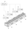
- FIG. 1 is a schematic diagram of a conveying device 1 according to one embodiment of the present invention.
- the conveying device 1 has a conveying path 2 having a number of modules 3. Each module 3 is linear and connected end to end. A number of actuators 5 that perform work are arranged near the conveying path 2. The positions of the modules 3 facing the actuators 5 are identified by unique position numbers A, B, C, and D.
- the conveying path 2 is provided with a belt conveyor 6 and a removable module 7.
- the belt conveyor 6 moves the slider 4 in the opposite direction to the module 3.
- the removable module 7 transfers the slider 4 between the module 3 and the belt conveyor 6.
- the conveying path 2 may be arranged in a vertical plane and the slider 4 may be circulated vertically, or the conveying path 2 may be arranged in a horizontal plane and the slider 4 may be circulated horizontally.
- the conveying device 1 is controlled by a centralized controller 8.
- the centralized controller 8 is a general-purpose PLC (Programmable Logic Controller), a personal computer, etc.
- the centralized controller 8 includes a processor, memory, and a communication interface.
- the memory includes ROM and RAM.
- the centralized controller 8 For example, the centralized controller 8 generates a target position command to move the slider 4 to position number A and sends it to the controller 9.
- the module controller of the module 3 sends a signal to the centralized controller 8 via the controller 9 that the slider 4 has reached position number A.
- the centralized controller 8 receives this signal, it sends a command to the actuator controller 10 to start work.
- the centralized controller 8 moves the slider 4 to position number B.
- the centralized controller 8 moves the slider 4 to the attachment/detachment module 7 and the belt conveyor 6.
- the actuator 5 is controlled by an actuator controller 10.
- the actuator controller 10 is a PLC, a personal computer, etc.
- the actuator controller 10 includes a processor, a memory, and a communication interface.
- the centralized controller 8 and the controllers 9 are connected by a communication link 12 such as DeviceNet, EtherCAT, or EtherNET/IP.
- the centralized controller 8 and the actuator controllers 10 are similarly connected by a communication link 13.
- the controller 9 and the module controllers of the modules 3 are connected by a communication line 14 capable of synchronous communication such as RS485 or I2C.
- the controller 9 executes the configuration software 11 when the conveying device 1 is started up.
- the memory 36 (see FIG. 6) of the controller 9 stores machine coordinates (movement coordinates) corresponding to the unique position numbers A, B, C, and D.
- the memory 36 of the controller 9 also stores the speed, acceleration, jerk, etc., when the module controller of the module 3 creates the motion profile (speed curve) of the slider 4. (Module)
- the module 3 includes a stator 20 having a plurality of coils 21. As shown in FIG. 4, a plurality of stators 20 (four in this embodiment) are provided for one module 3.
- FIG. 2 shows one stator 20. Each stator 20 includes a plurality of sets (two sets in this embodiment) of coils 21 for the U, V, and W phases. Power is supplied to the stator 20 by a drive circuit 22. A power line (not shown) is connected to the drive circuit 22.
- the drive circuit 22 is a power converter such as a PWM inverter.
- the drive circuit 22 is controlled by a module controller 24.
- a plurality of drive circuits 22 (four in this embodiment) are provided for one module controller 24.
- the drive circuit 22 is arranged on a driver board 23 shown in FIG. 3.
- the module controller 24 is also arranged on the driver board 23 shown in FIG. 3.
- the module 3 is equipped with a linear guide 25 that smoothly guides the linear movement of the slider 4.
- the rail 26 of the linear guide 25 is attached to the base 28 of the module 3.
- the carriage 27 of the linear guide 25 is attached to the slider 4.
- the module 3 is provided with sensors 29 for detecting the identification ID and current position of the slider 4.
- the sensors 29 are Hall sensors, magnetic resistance sensors, etc.
- the sensors 29 are arranged on a sensor board 30.
- the sensors 29 are provided corresponding to each stator 20. In this embodiment, four sensors 29 are provided.
- the slider 4 includes a driving permanent magnet 31 that serves as a mover of a linear motor. As shown in Fig. 5, the slider 4 includes a scale 32 that is parallel to the driving permanent magnet 31. The sensor 29 detects the magnetic field of the scale 32 to detect the identification ID and the current position of the slider 4. (Collision Prevention Control System)
- FIG 6 shows a configuration diagram of a collision prevention control system.
- the collision prevention control system includes a controller 9 and a plurality of module controllers 24.
- the controller 9 is a computer such as a personal computer.
- the controller 9 includes a processor 35, a memory 36, and a communication interface 37.
- the memory 36 includes a ROM and a RAM.
- the processor 35 executes a program stored in the memory 36.
- the controller 9 may be a microcomputer or an electric circuit such as an FPGA (Field Programmable Gate Array) or an ASIC (Application Specific Integrated Circuit).
- the centralized controller 8 and the controller 9 are connected by the above-mentioned communication link 12.
- the controller 9 and the module controller 24 are connected by a communication line 14 such as RS485 or I2C.
- Adjacent module controllers 24 are also connected by a communication line 15 such as RS485 or I2C.
- the controller 9 converts the target position command (position numbers A, B, C, D) for the slider 4 received from the centralized controller 8 into a target position command (movement coordinates) and transmits the target position command for the slider 4 to all module controllers 24.
- the module controller 24 is a microcomputer.
- the module controller 24 includes a processor 38, a memory 39, a communication interface 40, and an interface circuit 41.
- the module controller 24 may be a computer such as a personal computer, or may be an electric circuit such as an FPGA or ASIC.
- the module controller 24 receives a target position command (movement coordinates) for the slider 4 from the controller 9.
- the module controller 24 of the module 3 in which the slider 4 exists creates a motion profile (speed curve, etc.) for the slider 4 based on this target position command, generates a movement command (position command and speed command, or position command), and controls the drive circuit 22.
- the module controller 24 switches the drive circuit 22.
- the module controller 24 of the other module 3 takes over the motion profile and controls the drive circuit 22 of the other module 3.
- the module controller 24 includes an interface circuit 41.
- the interface circuit 41 processes the output signal of the sensor 29 that detects the current position of the slider 4 so that it can be feedback-controlled.
- the interface circuit 41 also processes the output signal of the current sensor 42 that detects the current in the stator 20 so that it can be feedback-controlled.
- the processor 38 of the module controller 24 performs position control, speed control, and current control of the slider 4. That is, the processor 38 generates a speed command based on the deviation between the position command of the movement command and the current position detected by the sensor 29. Then, the processor 38 generates a current command based on the deviation between the speed command and the current speed detected by the sensor 29. Then, the processor 38 generates a voltage command based on the deviation between the current command and the current current detected by the current sensor 42.
- the drive circuit 22 converts DC power to AC power using switching elements based on the voltage command generated by the processor 38, and supplies the AC power to the stator 20. (Collision prevention control method)
- Figure 7 shows a flowchart of the operation of the controller 9.
- the controller 9 receives a target position command (position number A, B, C, D) from the centralized controller 8 (S1)
- the controller 9 converts the target position command (position number A, B, C, D) into a target position command (movement coordinates) and transmits the target position command (movement coordinates) to all module controllers 24 (S2).
- the controller 9 also transmits information such as speed, acceleration, and jerk to create a motion profile (speed curve) of the slider 4 to all module controllers 24.
- the controller 9 receives slider information from the module controller 24 of the module 3 in which the slider 4 exists (S3).
- the slider information includes the identification ID, current position, current speed, and interference area of the slider 4.
- the identification ID is a number for identifying the slider 4.
- the current position is the current position of the slider 4 detected by the sensor 29.
- the current speed is the current speed of the slider 4 detected by the sensor 29.
- the interference area is, in other words, an area where other sliders 4 are prohibited from entering. As shown in FIG. 9, the interference area is the distance until the slider 4 decelerates and stops.
- the interference area is defined by the positive side safe stop position Xcw in the traveling direction of the slider 4 and the negative side safe stop position Xccw in the opposite direction.
- the scan time travel distance is the distance that the slider 4 travels during a position update period of the controller 9.
- the scan time travel distance is determined as in Equation 2.
- Scan time travel distance (mm) number of sliders x ⁇ s x speed (mm/s)
- ⁇ is the time from when the controller 9 inquires of one of the module controllers 24 about slider information until when one of the module controllers 24 responds to the controller 9 with the slider information.
- the deceleration stop distance is the distance when the slider 4 immediately decelerates to a stop.
- the deceleration stop distance is determined as shown in Equation 3.
- Equation 3 an emergency stop deceleration that is greater than the deceleration used to create the motion profile (speed curve) is used.
- the slider size (+) (mm) is the length from the center of the slider 4 to the end of the slider 4 in the direction of travel.
- the slider size (+) uses the longer of the slider 4 or the pallet 16.
- a margin may or may not be provided.
- the negative side safe stop position Xccw is set to 0 when the slider 4 is moving in the cw direction or when the slider 4 is stopped.
- the negative side safe stop position Xccw is set in the same manner as in Equation 1.
- the positive side safe stop position Xcw is set to, for example, 0 when the slider 4 moves in the ccw direction or when the slider 4 is stopped.
- the controller 9 receives slider information from the module controller 24 of the module 3 in which the slider 4 exists (S3). Then, the controller 9 transmits the received slider information to all module controllers 24 (S4). This allows all module controllers 24 to share the slider information.
- the slider information sent from the controller 9 to the module controller 24 is represented in the table format of Table 1, for example.
- FIG 8 shows a flowchart of the operation of the module controller 24.
- the module controller 24 of the module 3 in which the slider 4 to be controlled is located receives slider information from the controller 9 (S11).
- the module controller 24 determines whether the slider 4 to be controlled, which is assumed to have moved to the target position, will interfere with the interference area of the adjacent slider 4 (the slider 4 ahead in the traveling direction) (S12). If there is no interference, the module controller 24 sets the target position A received from the controller 9 as the target position (S13) and creates a motion profile (speed curve) based on the target position A (S15).
- the module controller 24 changes the target position to a provisional target position A1 to avoid interference (S14), and creates a motion profile based on the provisional target position A1 (S15).
- the module controller 24 generates a movement command (position command and speed command, or position command) based on the motion profile, and controls the drive circuit 22 to feedback control the slider 4 to be controlled (S16).
- the operation of the module controller (S12) to (S15) will be explained in detail by dividing it into patterns.
- the current position of the slider 4A to be controlled is A
- the current position of the adjacent slider 4B received from the controller 9 is B.
- the interference area 18 (+) of slider 4B is the plus side safe stop position Xcw received from the controller 9.
- the interference area 18 (-) of slider 4B is determined from the minus side safe stop position Xccw and slider size (-) received from the controller 9.
- the plus side safe stop position Xcw, minus side safe stop position Xccw, and slider size (+) (-) are stored in the memory 39 of the module controller 24.
- the symbols 19 (+) (-) indicate the slider size (+) (-) of slider 4A.
- the module controller 24 changes the target position from target position A received from the controller 9 to provisional target position A1 to avoid interference. Then, based on provisional target position A1, the velocity curve 17 is changed to velocity curve 17-1, shown by the dashed line in FIG. 11(a).
- the velocity curve 17-1 is updated at a predetermined update period (for example, 1 ms). As shown in FIG. 11(b), after a predetermined time has elapsed, when the slider 4B moves to the current position B shown in FIG. 11(b), the slider 4A will no longer interfere with the slider 4B even if it moves to the target position A. At this time, the module controller 24 resets the target position to the target position A received from the controller 9, and returns the velocity curve 17-1 to the original velocity curve 17. As a result, in this case, the operation of the slider 4A is not affected by the slider 4B.
- a predetermined update period for example, 1 ms
- Figures 12(a) and (b) show an example in which slider 4B is stopped.
- the module controller 24 changes target position A of slider 4A to provisional target position A1 to avoid the interference. Then, based on provisional target position A1, the velocity curve 17 is changed to velocity curve 17-1, shown by the dashed line in Figure 12(a).
- the slider 4B remains stopped even after a predetermined time has elapsed.
- the module controller 24 continues to hold the provisional target position A1 and stops the slider 4A at the provisional target position A1.
- Figures 13(a) and (b) show an example of slider 4B operating at a low speed.
- the module controller 24 changes target position A to provisional target position A1 to avoid the interference. Then, based on provisional target position A1, the speed curve 17 is changed to speed curve 17-1, shown by the dashed line in Figure 13(a).
- the module controller 24 changes the provisional target position A1 to a new provisional target position A2 and generates a speed curve 17-2. At this time, slider 4A repeatedly accelerates and decelerates until it reaches the same speed as slider 4B.
- Figures 14(a) and (b) show an example of slider 4B moving at high speed.
- the module controller 24 changes target position A to provisional target position A1 to avoid the interference. Then, based on provisional target position A1, the velocity curve 17 is changed to velocity curve 17-1, shown by the dashed line in Figure 14(a).
- the module controller 24 changes the provisional target position A1 to a new provisional target position A2 in accordance with the movement of slider 4B, and generates a new velocity curve 17-2.
- the new velocity curve 17-2 becomes closer to the original velocity curve 17.
- FIG. 15(a), (b), and (c) show an example in which slider 4A and slider 4B are moving facing each other.
- Slider 4A is controlled by the module controller 24 of the module 3 in which slider 4A is present.
- Slider 4B is controlled by the module controller 24 of the module 3 in which slider 4B is present.
- FIG. 15(a) at the start of the operation, slider 4A and slider 4B are separated. Slider 4A moves based on a velocity curve 33, and slider 4B moves based on a velocity curve 34.
- neither slider 4A nor slider 4B decelerates until the interference region 18 of slider 4A and the interference region 18 of slider 4B overlap.
- the module controller 24 of the module 3 in which the slider 4A exists changes the target position A to a provisional target position A1 that avoids interference, and changes the speed curve 33 to a speed curve 33-1 shown by a dashed line in Figure 15(c) based on the provisional target position A1. Then, the slider 4A is decelerated and stopped at an emergency stop deceleration that is greater than the deceleration when the sliders 4A and 4B move in the same direction.
- the module controller 24 of the module 3 in which the slider 4B exists changes the target position B to a provisional target position B1, changes the speed curve 34 to a speed curve 34-1, and decelerates and stops the slider 4B at the same emergency stop deceleration as the slider 4A. This makes it possible to prevent the sliders 4A and 4B from colliding with each other. When stopped, the slider 4A and the slider 4B are separated by a margin x 2. (effect)
- the control for collision prevention is distributed to the module controllers 24 of the modules 3 in which the sliders 4 to be controlled are located, the calculation load on the controller 9 and the centralized controller 8 can be reduced. Also, if a module controller 24 receives slider information from other module controllers 24 in distant locations via multiple module controllers 24, it takes time to receive the slider information. By having a module controller 24 receive slider information from other module controllers 24 via the controller 9, the time it takes to receive the slider information can be shortened.
- the slider information includes the identification ID, current position, and interference area of the slider 4, enabling a variety of controls to prevent collisions.
- the module controller 24 changes the target position of the slider 4 to the provisional target position to avoid the interference, so that the slider 4 to be controlled is not stopped unnecessarily, and the throughput of the conveying device 1 is improved.
- the controlled slider 4 and an adjacent slider 4 move in directions toward each other, the controlled slider 4 is decelerated and stopped at an emergency stop deceleration that is greater than the deceleration when they move in the same direction, so that collision between the two sliders 4 can be safely prevented.
- the interference area includes the deceleration and stopping distance until the slider 4 decelerates and stops, so collisions between the two sliders 4 when they move toward each other can be safely prevented.
- the interference region includes the scan time movement distance that the slider 4 moves during the position update period of the controller 9, so collisions between the two sliders 4 moving in directions toward each other can be safely prevented.
- the controller 9 transmits the target position command for the slider 4 received from the centralized controller 8 to the module controller 24, thereby reducing the calculation load on the centralized controller 8.
- the module controller of the module in which the slider to be controlled is located may calculate the distance between the slider to be controlled and an adjacent slider based on the slider's identification ID and current position information, and stop the slider to be controlled when this distance is equal to or less than a preset threshold.
- four drive circuits are provided for one module controller, but one drive circuit may be provided for one module controller.
- the centralized controller and the controller are separate, but the centralized controller and the controller may be integrated and the controller functions may be incorporated into the centralized controller.
Landscapes
- Engineering & Computer Science (AREA)
- Power Engineering (AREA)
- Control Of Conveyors (AREA)
- Control Of Linear Motors (AREA)
Abstract
集中コントローラの計算負荷を低減できる衝突防止制御システムを提供する。 衝突防止制御システムは、コントローラ(9)と、複数のモジュールのドライブ回路(22)を制御する複数のモジュールコントローラ(24)と、を備える。スライダが存在するモジュールのモジュールコントローラ(24)がスライダの少なくとも識別IDと現在位置を含むスライダ情報をコントローラ(9)に送信する。コントローラ(9)がスライダ情報を複数のモジュールコントローラ(24)に送信する。制御対象のスライダが存在するモジュールのモジュールコントローラ(24)が、隣接するスライダとの衝突を防止するように制御対象のスライダを制御する。
Description
本発明は、複数のモジュールを有する搬送経路を複数のスライダが移動する搬送装置に用いられる衝突防止制御システム及び方法に関する。
搬送経路を複数のスライダが移動する搬送装置が開発されている。搬送経路は、複数のモジュールを組み合わせて構成される。モジュールには、リニアモータの固定子となる複数のコイル、複数のコイルに供給する電力を制御するドライブ回路が設けられる。スライダには、リニアモータの可動子となる永久磁石が設けられる。複数のコイルに供給する電力をドライブ回路によって制御し、複数のコイルに移動磁場を発生させると、スライダが搬送経路に沿って移動する。
この種の搬送装置には、従来のベルトコンベヤに比べて、優れた柔軟性があるという特徴がある。例えば、従来のベルトコンベヤのように複数のスライダを一斉に移動させる必要がなく、複数のスライダを個別に移動させ、位置決めできる。また、モジュールを適宜組み替えれば、用途に応じた適切な搬送経路にすることができる。このため、この種の搬送装置は、様々な用途(製造、加工、パッケージング等)で利用されている。
典型的な搬送経路は閉じていて、スライダが閉じた搬送経路を繰り返し移動する。搬送経路の近傍には、スライダと協働して仕事を行う複数のアクチュエータが配置される。例えば、スライダが製品供給アクチュエータの前で停止すると、アクチュエータがスライダに製品を供給する。次に、スライダが他のアクチュエータの前で停止すると、他のアクチュエータがスライダ上の製品を加工、組立て等する。次に、スライダが製品取出しアクチュエータの前で停止すると、アクチュエータがスライダから製品を取り出す。以降は上記のサイクルを繰り返す。
複数のスライダが搬送経路を移動する搬送装置においては、スライダ同士の衝突を防止することが重要である。例えば、進行方向前方のスライダが停止したとき、衝突を防止するために後方のスライダも停止する必要がある。
従来の衝突防止制御方法として、前方のスライダと後方のスライダのスライダ間距離が予め設定された閾値以下のとき、後方のスライダを停止させることが行われている(特許文献1参照)。
しかし、従来の衝突防止制御方法においては、スライダの衝突防止のための計算や制御を集中コントローラが行っている。このため、スライダの数が増えるにしたがって、集中コントローラの計算負荷が増大するという課題がある。
本発明は上記の課題に鑑みてなされたものであり、集中コントローラの計算負荷を低減できる衝突防止制御システム及び方法を提供することを目的とする。
上記課題を解決するために、本発明の一態様は、複数のモジュールを有する搬送経路を複数のスライダが移動する搬送装置に用いられる衝突防止制御システムであって、コントローラと、複数のモジュールのドライブ回路を制御する複数のモジュールコントローラと、を備え、前記スライダが存在するモジュールのモジュールコントローラが前記スライダの少なくとも識別IDと現在位置を含むスライダ情報を前記コントローラに送信し、前記コントローラが前記スライダ情報を前記複数のモジュールコントローラに送信し、制御対象のスライダが存在するモジュールのモジュールコントローラが、隣接するスライダとの衝突を防止するように制御対象のスライダを制御する衝突防止制御システムである。
本発明の他の態様は、複数のモジュールを有する搬送経路を複数のスライダが移動する搬送装置に用いられる衝突防止制御方法であって、前記搬送装置が、コントローラと、複数のモジュールのドライブ回路を制御する複数のモジュールコントローラと、を備え、前記スライダが存在するモジュールのモジュールコントローラが前記スライダの少なくとも識別情報と位置情報を含むスライダ情報を前記コントローラに送信し、前記コントローラが前記スライダ情報を前記複数のモジュールコントローラに送信し、制御対象のスライダが存在するモジュールのモジュールコントローラが、隣接するスライダとの衝突を防止するように制御対象のスライダを制御する衝突防止制御方法である。
本発明によれば、衝突防止のための制御を制御対象のスライダが存在するモジュールのモジュールコントローラに分散させるので、コントローラや集中コントローラの計算負荷を低減できる。また、モジュールコントローラが離れた位置にある他のモジュールコントローラから複数のモジュールコントローラを介してスライダ情報を受け取るのでは、スライダ情報を受信するまでに時間がかかる。モジュールコントローラがコントローラを介して他のモジュールコントローラからスライダ情報を受信するようにすることで、スライダ情報を受信するまでの時間を短縮できる。
以下、添付図面に基づいて、本発明の実施形態の衝突防止制御システム及び方法を説明する。ただし、本発明の衝突防止制御システム及び方法は種々の形態で具体化することができ、本明細書に記載される実施形態に限定されるものではない。本実施形態は、明細書の開示を十分にすることによって、当業者が発明を十分に理解できるようにする意図をもって提供されるものである。
(搬送装置)
(搬送装置)
図1は、本発明の一実施形態の搬送装置1の概略図である。搬送装置1は、複数のモジュール3を有する搬送経路2を備える。各モジュール3は直線状であり、端と端が接続される。搬送経路2の近傍には、仕事を行う複数のアクチュエータ5が配置される。アクチュエータ5に対面するモジュール3の位置は、固有の位置番号A,B,C,Dで識別される。
閉じた搬送経路2を構成するために、搬送経路2には、ベルトコンベヤ6と着脱モジュール7が設けられる。ベルトコンベヤ6は、スライダ4をモジュール3とは反対方向に移動させる。着脱モジュール7は、モジュール3とベルトコンベヤ6との間でスライダ4を受け渡す。搬送経路2を垂直面内に配置し、スライダ4を垂直循環させてもよいし、搬送経路2を水平面内に配置し、スライダ4を水平循環させてもよい。
搬送装置1は、集中コントローラ8によって制御される。集中コントローラ8は、汎用PLC(Programmable Logic Controller)、パーソナルコンピュータ等である。集中コントローラ8は、プロセッサ、メモリ、通信インターフェースを備える。メモリは、ROMとRAMを備える。
例えば、集中コントローラ8は、スライダ4を位置番号Aに移動させる目標位置指令を生成し、コントローラ9に送信する。スライダ4がA点に到達すると、モジュール3のモジュールコントローラがコントローラ9を介して、スライダ4が位置番号Aに到達したという信号を集中コントローラ8に送る。集中コントローラ8は、この信号を受け取ったらアクチュエータコントローラ10に仕事開始の指令を送信する。アクチュエータ5の仕事が終わったら、集中コントローラ8は、スライダ4を位置番号Bに移動させる。全てのアクチュエータ5の仕事が終わったら、集中コントローラ8は、スライダ4を着脱モジュール7、ベルトコンベヤ6に移動させる。
アクチュエータ5は、アクチュエータコントローラ10によって制御される。アクチュエータコントローラ10は、PLC、パーソナルコンピュータ等である。アクチュエータコントローラ10は、プロセッサ、メモリ、通信インターフェースを備える。
集中コントローラ8とコントローラ9は、DeviceNet、EtherCAT、EtherNET/IP等の通信リンク12によって接続される。集中コントローラ8とアクチュエータコントローラ10も同様であり、通信リンク13によって接続される。コントローラ9とモジュール3のモジュールコントローラは、RS485、I2C等の同期通信可能な通信回線14によって接続される。
コントローラ9は、搬送装置1の立ち上げ時にコンフィグソフト11を実行する。これにより、コントローラ9のメモリ36(図6参照)には、固有の位置番号A、B、C、Dに対応する機械座標(移動座標)が記憶される。また、コントローラ9のメモリ36には、モジュール3のモジュールコントローラがスライダ4の運動プロファイル(速度曲線)を作成するときの速度、加速度、加加速度等が記憶される。
(モジュール)
(モジュール)
図2に示すように、モジュール3は、複数のコイル21を有する固定子20を備える。図4に示すように、1つのモジュール3に対して、複数(この実施形態では4つ)の固定子20が設けられる。図2には1つの固定子20を示す。各固定子20は、U,V,W相のコイル21を複数組(この実施形態では2組)備える。固定子20には、ドライブ回路22によって電力が供給される。ドライブ回路22には、図示しない電力線が接続される。ドライブ回路22は、PWMインバータ等の電力変換器である。ドライブ回路22は、モジュールコントローラ24によって制御される。1つのモジュールコントローラ24に対して複数(この実施形態では4つ)のドライブ回路22が設けられる。ドライブ回路22は、図3に示すドライバ基板23に配置される。モジュールコントローラ24も、図3に示すドライバ基板23に配置される。
図3に示すように、モジュール3は、スライダ4の直線移動を円滑に案内するリニアガイド25を備える。リニアガイド25のレール26がモジュール3のベース28に取り付けられる。リニアガイド25のキャリッジ27がスライダ4に取り付けられる。
モジュール3には、スライダ4の識別IDと現在位置を検出するためのセンサ29が設けられる。センサ29は、ホールセンサ、磁気抵抗センサ等である。センサ29は、センサ基板30に配置される。センサ29は、各固定子20に対応して設けられる。この実施形態では、4つのセンサ29が設けられる。
スライダ4は、リニアモータの可動子となる駆動用永久磁石31を備える。図5に示すように、スライダ4は、駆動用永久磁石31と平行にスケール32を備える。センサ29は、スケール32の磁場を検出することによって、スライダ4の識別IDと現在位置を検出する。
(衝突防止制御システム)
(衝突防止制御システム)
図6は、衝突防止制御システムの構成図を示す。衝突防止制御システムは、コントローラ9と、複数のモジュールコントローラ24を備える。コントローラ9は、パーソナルコンピュータ等のコンピュータである。コントローラ9は、プロセッサ35、メモリ36、通信インターフェース37を備える。メモリ36は、ROMとRAMを備える。プロセッサ35は、メモリ36に記憶されたプログラムを実行する。コントローラ9は、マイコンでもよいし、FPGA(Field Programmable Gate Array)、ASIC(Application Specific Integrated Circuit)等の電気回路でもよい。
集中コントローラ8とコントローラ9とは、上記の通信リンク12によって接続される。コントローラ9とモジュールコントローラ24は、RS485、I2C等の通信回線14によって接続される。隣接するモジュールコントローラ24も、RS485、I2C等の通信回線15によって接続される。
コントローラ9は、集中コントローラ8から受信したスライダ4の目標位置指令(位置番号A,B,C,D)を目標位置指令(移動座標)に変換して、全てのモジュールコントローラ24にスライダ4の目標位置指令を送信する。
モジュールコントローラ24は、マイコンである。モジュールコントローラ24は、プロセッサ38、メモリ39、通信インターフェース40,インターフェース回路41を備える。モジュールコントローラ24は、パーソナルコンピュータ等のコンピュータでもよいし、FPGA、ASIC等の電気回路でもよい。
モジュールコントローラ24は、コントローラ9からスライダ4の目標位置指令(移動座標)を受信する。スライダ4が存在するモジュール3のモジュールコントローラ24は、この目標位置指令に基づいて、スライダ4の運動プロファイル(速度曲線等)を作成し、移動指令(位置指令及び速度指令、又は位置指令)を生成し、ドライブ回路22を制御する。スライダ4が固定子20から他の固定子20に乗り移ったら、モジュールコントローラ24は、ドライブ回路22を切り換える。スライダ4がモジュール3から他のモジュール3に乗り移ったら、他のモジュール3のモジュールコントローラ24が運動プロファイルを引き継ぎ、他のモジュール3のドライブ回路22を制御する。
モジュールコントローラ24は、インターフェース回路41を備える。インターフェース回路41は、スライダ4の現在位置を検出するセンサ29の出力信号をフィードバック制御できるように信号処理する。また、インターフェース回路41は、固定子20の電流を検出する電流センサ42の出力信号をフィードバック制御できるように信号処理する。
モジュールコントローラ24のプロセッサ38は、スライダ4の位置制御、速度制御、電流制御を行う。すなわち、プロセッサ38は、移動指令の位置指令とセンサ29が検出した現在位置との偏差に基づき、速度指令を生成する。そして、速度指令とセンサ29が検出した現在速度との偏差に基づき、電流指令を生成する。そして、電流指令と電流センサ42が検出した現在電流との偏差に基づき、電圧指令を生成する。ドライブ回路22は、プロセッサ38が生成する電圧指令に基づき、スイッチング素子により直流電力を交流電力に変換し、交流電力を固定子20に供給する。
(衝突防止制御方法)
(衝突防止制御方法)
図7は、コントローラ9の動作のフローチャートを示す。コントローラ9が集中コントローラ8から目標位置指令(位置番号A,B,C,D)を受信すると(S1)、コントローラ9は、目標位置指令(位置番号A,B,C,D)を目標位置指令(移動座標)に変換し、目標位置指令(移動座標)を全てのモジュールコントローラ24に送信する(S2)。また、コントローラ9は、スライダ4の運動プロファイル(速度曲線)を作成するための速度、加速度、加加速度等の情報を全てのモジュールコントローラ24に送信する。
次に、コントローラ9は、スライダ4が存在するモジュール3のモジュールコントローラ24からスライダ情報を受信する(S3)。スライダ情報は、スライダ4の識別ID、現在位置、現在速度、及び干渉領域を含む。
識別IDは、スライダ4を特定するための番号である。現在位置は、センサ29が検出したスライダ4の現在位置である。現在速度は、センサ29が検出したスライダ4の現在速度である。干渉領域は、言い換えれば他のスライダ4の侵入禁止領域である。図9に示すように、干渉領域は、スライダ4が減速停止するまでの距離である。干渉領域は、スライダ4の進行方向のプラス側安全停止位置Xcwと逆方向のマイナス側安全停止位置Xccwによって画定される。
図9に示すように、スライダ4が移動座標上をcw方向に移動するとき、プラス側安全停止位置Xcwは、式1のように決定される。
(式1)
プラス側干渉領域Xcw=スキャンタイム移動距離(mm)+減速停止距離(mm)+スライダサイズ(+)(mm)+マージン(mm)
(式1)
プラス側干渉領域Xcw=スキャンタイム移動距離(mm)+減速停止距離(mm)+スライダサイズ(+)(mm)+マージン(mm)
スキャンタイム移動距離は、コントローラ9の位置更新周期の間にスライダ4が移動する距離である。スキャンタイム移動距離は、式2のように決定される。
(式2)
スキャンタイム移動距離(mm)=スライダ台数×αμs×速度(mm/s)
ここで、αは、コントローラ9が1台のモジュールコントローラ24にスライダ情報を問い合わせて、1台のモジュールコントローラ24がコントローラ9にスライダ情報を回答するまでの時間である。
(式2)
スキャンタイム移動距離(mm)=スライダ台数×αμs×速度(mm/s)
ここで、αは、コントローラ9が1台のモジュールコントローラ24にスライダ情報を問い合わせて、1台のモジュールコントローラ24がコントローラ9にスライダ情報を回答するまでの時間である。
減速停止距離は、スライダ4が直ちに減速停止したときの距離である。減速停止距離は、式3のように決定される。
(式3)
減速停止距離(mm)=(減速度(mm/s2)×0.5+速度(mm/s))×速度(mm/s)/減速度(mm/s2)
式3の減速度には、運動プロファイル(速度曲線)を作成するときの減速度よりも大きい緊急停止減速度を使用する。
(式3)
減速停止距離(mm)=(減速度(mm/s2)×0.5+速度(mm/s))×速度(mm/s)/減速度(mm/s2)
式3の減速度には、運動プロファイル(速度曲線)を作成するときの減速度よりも大きい緊急停止減速度を使用する。
図9に示すように、スライダサイズ(+)(mm)は、スライダ4の中心からスライダ4の進行方向の端までの長さである。スライダサイズ(+)には、スライダ4又はパレット16の長い方を使用する。マージンは設けても設けなくてもよい。
マイナス側安全停止位置Xccwは、スライダ4がcw方向に移動するとき、又はスライダ4が停止中のときには、0に設定される。
スライダ4が移動座標上をccw方向に移動するとき、マイナス側安全停止位置Xccwは、式1と同様に設定される。プラス側安全停止位置Xcwは、スライダ4がccw方向に移動するとき、又はスライダ4が停止中のとき、例えば0に設定される。
再び図7に示すように、コントローラ9は、スライダ4が存在するモジュール3のモジュールコントローラ24からスライダ情報を受信する(S3)。そして、受信したスライダ情報を全てのモジュールコントローラ24に送信する(S4)。これにより、全てのモジュールコントローラ24がスライダ情報を共有する。
コントローラ9がモジュールコントローラ24に送信するスライダ情報は、例えば表1のテーブル形式で表される。

図8は、モジュールコントローラ24の動作のフローチャートを示す。制御対象のスライダ4が存在するモジュール3のモジュールコントローラ24(以下、単にモジュールコントローラ24という)は、コントローラ9からスライダ情報を受信する(S11)。次に、モジュールコントローラ24は、目標位置に移動したと仮定した制御対象のスライダ4が隣り合うスライダ4(進行方向前方のスライダ4)の干渉領域に干渉するか否かを判断する(S12)。干渉しないとき、モジュールコントローラ24は、コントローラ9から受信した目標位置Aを目標位置に設定し(S13)、目標位置Aに基づいて運動プロファイル(速度曲線)を作成する(S15)。干渉するとき、モジュールコントローラ24は、干渉を回避するように目標位置を暫定目標位置A1に変化させ(S14)、暫定目標位置A1に基づいて運動プロファイルを作成する(S15)。次に、モジュールコントローラ24は、運動プロファイルに基づいて移動指令(位置指令と速度指令、又は位置指令)を生成し、ドライブ回路22を制御することによって、制御対象のスライダ4をフィードバック制御する(S16)。
以下に、モジュールコントローラの動作(S12)~(S15)をパターン分けして詳しく説明する。図10に示すように、制御対象のスライダ4Aの現在位置はAであり、コントローラ9から受信した隣り合うスライダ4Bの現在位置はBであるとする。スライダ4Bの干渉領域18(+)は、コントローラ9から受信したプラス側安全停止位置Xcwである。スライダ4Bの干渉領域18(-)は、コントローラ9から受信したマイナス側安全停止位置Xccwとスライダサイズ(-)によって求める。プラス側安全停止位置Xcw、マイナス側安全停止位置Xccw、スライダサイズ(+)(-)は、モジュールコントローラ24のメモリ39に記憶されている。符号19(+)(-)は、スライダ4Aのスライダサイズ(+)(-)を示す。
図10に示すように、制御対象のスライダ4Aがコントローラ9から受信した目標位置Aまで移動したと仮定する。目標位置Aにあるスライダ4を破線で示す。目標位置Aまで移動しても、スライダ4Aがスライダ4Bの干渉領域18と干渉しないとき、モジュールコントローラ24は、目標位置をコントローラ9から受信した目標位置Aに設定する。そして、図10に示すように、運動プロファイル(台形の速度曲線17)を作成する。なお、この速度曲線17は、スライダ4Aが移動する過程で、徐々に加速し、その後一定速になり、その後徐々に減速して目標位置Aで停止することを意味する。
図11(a)に示すように、目標位置Aまで移動したと仮定したスライダ4Aが隣り合うスライダ4Bの干渉領域18と干渉するとき、モジュールコントローラ24は、干渉を回避するように目標位置をコントローラ9から受信した目標位置Aから暫定目標位置A1に変化させる。そして、暫定目標位置A1を元に速度曲線17を図11(a)の破線で示す速度曲線17-1に変化させる。
速度曲線17-1は、所定の更新周期(例えば1ms)毎に更新される。図11(b)に示すように、所定時間経過後、スライダ4Bが図11(b)に示す現在位置Bまで移動すると、スライダ4Aは目標位置Aまで移動してもスライダ4Bに干渉しなくなる。このとき、モジュールコントローラ24は、目標位置をコントローラ9から受信した目標位置Aに再設定し、速度曲線17-1を当初の速度曲線17に戻す。結果的には、この場合、スライダ4Aの動作はスライダ4Bに影響されないことになる。
図12(a)(b)は、スライダ4Bが停止中の例を示す。図12(a)に示すように、目標位置Aまで移動したと仮定したスライダ4Aが停止中のスライダ4Bの干渉領域18と干渉するとき、モジュールコントローラ24は、干渉を回避するようにスライダ4Aの目標位置Aを暫定目標位置A1に変化させる。そして、暫定目標位置A1を元に速度曲線17を図12(a)の破線で示す速度曲線17-1に変化させる。
図12(b)に示すように、所定時間経過後もスライダ4Bが停止したままである。モジュールコントローラ24は、暫定目標位置A1を保持し続け、スライダ4Aを暫定目標位置A1に停止させる。
図13(a)(b)は、スライダ4Bが低速動作中の例を示す。図13(a)に示すように、目標位置Aまで移動したと仮定したスライダ4Aが低速動作中のスライダ4Bの干渉領域18と干渉するとき、モジュールコントローラ24は、干渉を回避するように目標位置Aを暫定目標位置A1に変化させる。そして、暫定目標位置A1を元に速度曲線17を図13(a)の破線で示す速度曲線17-1に変化させる。
図13(b)に示すように、スライダ4Aがスライダ4Bに追いついたとき、モジュールコントローラ24は、暫定目標位置A1を新たな暫定目標位置A2に変化させ、速度曲線17-2を生成する。このとき、スライダ4Aは、加減速を繰り返しながらスライダ4Bと同速度となるまで減速する。
図14(a)(b)は、スライダ4Bが高速動作中の例を示す。図14(a)に示すように、目標位置Aまで移動したと仮定したスライダ4Aが高速動作中のスライダ4Bの干渉領域18と干渉するとき、モジュールコントローラ24は、干渉を回避するように目標位置Aを暫定目標位置A1に変化させる。そして、暫定目標位置A1を元に速度曲線17を図14(a)の破線で示す速度曲線17-1に変化させる。
図14(b)に示すように、所定時間後、スライダ4Bがスライダ4Aから離れたとき、モジュールコントローラ24は、スライダ4Bの動きに合わせて暫定目標位置A1を新たな暫定目標位置A2に変化させ、新たな速度曲線17-2を生成する。新たな速度曲線17-2は、当初の速度曲線17に近づいたものになる。
図15(a)(b)(c)は、スライダ4Aとスライダ4Bが向かい合って移動中の例を示す。スライダ4Aは、スライダ4Aが存在するモジュール3のモジュールコントローラ24が制御する。スライダ4Bは、スライダ4Bが存在するモジュール3のモジュールコントローラ24が制御する。図15(a)に示すように、動作開始時点では、スライダ4Aとスライダ4Bは離れている。スライダ4Aは、速度曲線33に基づいて移動し、スライダ4Bは、速度曲線34に基づいて移動する。図15(a)から図15(b)に示すように、スライダ4Aの干渉領域18とスライダ4Bの干渉領域18が重なるまでは、スライダ4A、スライダ4B共に減速しない。図15(b)から(c)に示すように、スライダ4Aの干渉領域18とスライダ4Bの干渉領域18が干渉するとき、スライダ4Aが存在するモジュール3のモジュールコントローラ24は、目標位置Aを干渉を回避する暫定目標位置A1に変化させ、暫定目標位置A1を元に速度曲線33を図15(c)の破線で示す速度曲線33-1に変化させる。そして、スライダ4Aとスライダ4Bが同一方向に移動するときの減速度よりも大きい緊急停止減速度でスライダ4Aを減速停止させる。同様に、スライダ4Bが存在するモジュール3のモジュールコントローラ24は、目標位置Bを暫定目標位置B1に変化させ、速度曲線34を速度曲線34-1に変化させ、スライダ4Aと同じ緊急停止減速度でスライダ4Bを減速停止させる。これにより、スライダ4Aとスライダ4Bの衝突を防止することができる。停止時には、スライダ4Aとスライダ4Bは、マージン×2だけ離れる。
(効果)
(効果)
本実施形態の衝突防止制御システム及び方法によれば、以下の効果を奏する。
衝突防止のための制御を制御対象のスライダ4が存在するモジュール3のモジュールコントローラ24に分散させるので、コントローラ9や集中コントローラ8の計算負荷を低減できる。また、モジュールコントローラ24が離れた位置にある他のモジュールコントローラ24から複数のモジュールコントローラ24を介してスライダ情報を受け取るのでは、スライダ情報を受信するまでに時間がかかる。モジュールコントローラ24がコントローラ9を介して他のモジュールコントローラ24からスライダ情報を受信するようにすることで、スライダ情報を受信するまでの時間を短縮できる。
スライダ情報が、スライダ4の識別ID、現在位置及び干渉領域を含むので、衝突を防止するための多様な制御が可能になる。
モジュールコントローラ24が、目標位置まで移動したと仮定した制御対象のスライダ4が隣り合うスライダ4の干渉領域と干渉するとき、干渉を回避するように制御対象のスライダ4の目標位置を暫定目標位置に変化させるので、制御対象のスライダ4を無駄に停止させることが無くなり、搬送装置1のスループットが向上する。
制御対象のスライダ4と隣接するスライダ4が互いに向かい合う方向に移動するとき、これらが同一方向に移動するときの減速度よりも大きい緊急停止減速度で制御対象のスライダ4を減速停止させるので、2つのスライダ4の衝突を安全に防止できる。
干渉領域が、スライダ4が減速して停止するまでの減速停止距離を含むので、2つのスライダ4が互いに向かい合う方向に移動するときの衝突を安全に防止できる。
干渉領域が、コントローラ9の位置更新周期の間にスライダ4が移動するスキャンタイム移動距離を含むので、2つのスライダ4が互いに向かい合う方向に移動するときの衝突を安全に防止できる。
コントローラ9が、集中コントローラ8から受信したスライダ4の目標位置指令をモジュールコントローラ24に送信するので、集中コントローラ8の計算負荷を低減できる。
なお、本発明は上記実施形態に具現化されるのに限られることはなく、本発明の要旨を変更しない範囲で他の実施形態に具現化できる。
例えば、制御対象のスライダが存在するモジュールのモジュールコントローラが、スライダの識別IDと現在位置の情報に基づいて、制御対象のスライダと隣り合うスライダとの間の距離を計算し、この距離が予め設定された閾値以下のとき、制御対象のスライダを停止させてもよい。
上記実施形態では、1つのモジュールコントローラに対して4つのドライブ回路を設けているが、1つのモジュールコントローラに対して1つのドライブ回路を設けてもよい。
上記実施形態では、集中コントローラとコントローラを分離しているが、集中コントローラとコントローラを一体化し、コントローラの機能を集中コントローラに組み込んでもよい。
本明細書は、2023年6月16日出願の特願2023-098880に基づく。この内容はすべてここに含めておく。
1…搬送装置、2…搬送経路、3…モジュール、4…スライダ、8…集中コントローラ、9…コントローラ、22…ドライブ回路
Claims (8)
- 複数のモジュールを有する搬送経路を複数のスライダが移動する搬送装置に用いられる衝突防止制御システムであって、
コントローラと、
複数のモジュールのドライブ回路を制御する複数のモジュールコントローラと、を備え、
前記スライダが存在するモジュールのモジュールコントローラが前記スライダの少なくとも識別IDと現在位置を含むスライダ情報を前記コントローラに送信し、
前記コントローラが前記スライダ情報を前記複数のモジュールコントローラに送信し、
制御対象のスライダが存在するモジュールのモジュールコントローラが、隣接するスライダとの衝突を防止するように制御対象のスライダを制御する衝突防止制御システム。 - 前記スライダ情報は、前記スライダの識別ID、現在位置及び干渉領域を含むことを特徴とする請求項1に記載の衝突防止制御システム。
- 前記モジュールコントローラは、目標位置まで移動したと仮定した制御対象のスライダが隣り合うスライダの干渉領域と干渉するとき、干渉を回避するように制御対象のスライダの目標位置を暫定目標位置に変化させることを特徴とする請求項2に記載の衝突防止制御システム。
- 前記モジュールコントローラは、制御対象のスライダと隣接するスライダが互いに向かい合う方向に移動するとき、これらが同一方向に移動するときの減速度よりも大きい緊急停止減速度で制御対象のスライダを減速停止させることを特徴とする請求項1又は2に記載の衝突防止制御システム。
- 前記干渉領域は、前記スライダが減速して停止するまでの減速停止距離を含むことを特徴とする請求項2又は3に記載の衝突防止制御システム。
- 前記干渉領域は、前記コントローラの位置更新周期の間に前記スライダが移動するスキャンタイム移動距離を含むことを特徴とする請求項5に記載の衝突防止制御システム。
- 前記コントローラが、集中コントローラから受信したスライダの目標位置指令を前記モジュールコントローラに送信することを特徴とする請求項1又は2に記載の衝突防止制御システム。
- 複数のモジュールを有する搬送経路を複数のスライダが移動する搬送装置に用いられる衝突防止制御方法であって、
前記搬送装置が、コントローラと、複数のモジュールのドライブ回路を制御する複数のモジュールコントローラと、を備え、
前記スライダが存在するモジュールのモジュールコントローラが前記スライダの少なくとも識別情報と位置情報を含むスライダ情報を前記コントローラに送信し、
前記コントローラが前記スライダ情報を前記複数のモジュールコントローラに送信し、
制御対象のスライダが存在するモジュールのモジュールコントローラが、隣接するスライダとの衝突を防止するように制御対象のスライダを制御する衝突防止制御方法。
Priority Applications (1)
| Application Number | Priority Date | Filing Date | Title |
|---|---|---|---|
| CN202480036189.1A CN121219955A (zh) | 2023-06-16 | 2024-05-10 | 碰撞防止控制系统以及方法 |
Applications Claiming Priority (2)
| Application Number | Priority Date | Filing Date | Title |
|---|---|---|---|
| JP2023098880A JP2024179758A (ja) | 2023-06-16 | 2023-06-16 | 衝突防止制御システム及び方法 |
| JP2023-098880 | 2023-06-16 |
Publications (1)
| Publication Number | Publication Date |
|---|---|
| WO2024257518A1 true WO2024257518A1 (ja) | 2024-12-19 |
Family
ID=93851847
Family Applications (1)
| Application Number | Title | Priority Date | Filing Date |
|---|---|---|---|
| PCT/JP2024/017361 Pending WO2024257518A1 (ja) | 2023-06-16 | 2024-05-10 | 衝突防止制御システム及び方法 |
Country Status (4)
| Country | Link |
|---|---|
| JP (1) | JP2024179758A (ja) |
| CN (1) | CN121219955A (ja) |
| TW (1) | TW202501191A (ja) |
| WO (1) | WO2024257518A1 (ja) |
Citations (1)
| Publication number | Priority date | Publication date | Assignee | Title |
|---|---|---|---|---|
| JP2022184755A (ja) * | 2021-05-31 | 2022-12-13 | ベーウントエル・インダストリアル・オートメイション・ゲゼルシャフト・ミト・ベシュレンクテル・ハフツング | 衝突監視装置を有する搬送システム及び当該搬送システムを稼働させるための方法 |
-
2023
- 2023-06-16 JP JP2023098880A patent/JP2024179758A/ja active Pending
-
2024
- 2024-05-10 CN CN202480036189.1A patent/CN121219955A/zh active Pending
- 2024-05-10 WO PCT/JP2024/017361 patent/WO2024257518A1/ja active Pending
- 2024-05-16 TW TW113118036A patent/TW202501191A/zh unknown
Patent Citations (1)
| Publication number | Priority date | Publication date | Assignee | Title |
|---|---|---|---|---|
| JP2022184755A (ja) * | 2021-05-31 | 2022-12-13 | ベーウントエル・インダストリアル・オートメイション・ゲゼルシャフト・ミト・ベシュレンクテル・ハフツング | 衝突監視装置を有する搬送システム及び当該搬送システムを稼働させるための方法 |
Also Published As
| Publication number | Publication date |
|---|---|
| JP2024179758A (ja) | 2024-12-26 |
| TW202501191A (zh) | 2025-01-01 |
| CN121219955A (zh) | 2025-12-26 |
Similar Documents
| Publication | Publication Date | Title |
|---|---|---|
| EP3501880B1 (en) | Linear drive system having central, distributed and group control | |
| US10994943B2 (en) | Method for operating a long stator linear motor with transport units and collision monitoring | |
| EP3537247B1 (en) | Method and apparatus for coordinating external device motion with motion of independent movers in a linear drive system | |
| EP2599186B1 (en) | System and method for providing power to a moving element | |
| JP5334709B2 (ja) | 被印刷物のためのセグメント化された搬送系の少なくとも2つのブリッジを個別化する方法 | |
| US8794426B2 (en) | Pallet-based position adjustment system and method | |
| US12421056B2 (en) | Transport system and method for operating a transport system with collision monitoring | |
| US10826370B2 (en) | Method for operating a long stator linear motor with switch | |
| US11413968B2 (en) | Method and apparatus for providing improved motion control of movers in an independent cart system | |
| EP3301809B1 (en) | Method and apparatus for interleaved switching of track segments in a motion control system | |
| US11780333B2 (en) | System and method for collision prevention in a linear motion system | |
| US10921800B2 (en) | Motor control device | |
| US12195062B2 (en) | System and method for controlling movers in an independent cart system during heavy traffic | |
| US20220306406A1 (en) | Method for operating a transport system in the form of a long-stator linear motor | |
| US12091265B2 (en) | Method of operating a transport system and transport system | |
| WO2024257518A1 (ja) | 衝突防止制御システム及び方法 | |
| KR102447060B1 (ko) | 부서지기 쉬운 물체를 운송하기 위한 운송 장치 및 운송 방법 | |
| JP2014047022A (ja) | 移動体の制御方法 | |
| JP4170567B2 (ja) | 工作機械の移動装置および工作機械の移動装置の制御方法 | |
| KR102289024B1 (ko) | 이송 장치 | |
| JP4596806B2 (ja) | 駆動制御装置及び駆動制御方法 | |
| JP2001002207A (ja) | 荷移載装置 | |
| JP2004255418A (ja) | プレス機械のワーク搬送装置 | |
| JP2009181149A (ja) | 搬送装置のモーション制御装置 | |
| JP2004195487A (ja) | フィーダの非常退避方法 |
Legal Events
| Date | Code | Title | Description |
|---|---|---|---|
| 121 | Ep: the epo has been informed by wipo that ep was designated in this application |
Ref document number: 24823140 Country of ref document: EP Kind code of ref document: A1 |
|
| WWE | Wipo information: entry into national phase |
Ref document number: 1020267000666 Country of ref document: KR |