WO2024257518A1 - 衝突防止制御システム及び方法 - Google Patents
衝突防止制御システム及び方法 Download PDFInfo
- Publication number
- WO2024257518A1 WO2024257518A1 PCT/JP2024/017361 JP2024017361W WO2024257518A1 WO 2024257518 A1 WO2024257518 A1 WO 2024257518A1 JP 2024017361 W JP2024017361 W JP 2024017361W WO 2024257518 A1 WO2024257518 A1 WO 2024257518A1
- Authority
- WO
- WIPO (PCT)
- Prior art keywords
- slider
- controller
- module
- collision prevention
- prevention control
- Prior art date
- Legal status (The legal status is an assumption and is not a legal conclusion. Google has not performed a legal analysis and makes no representation as to the accuracy of the status listed.)
- Ceased
Links
Images



Classifications
-
- B—PERFORMING OPERATIONS; TRANSPORTING
- B65—CONVEYING; PACKING; STORING; HANDLING THIN OR FILAMENTARY MATERIAL
- B65G—TRANSPORT OR STORAGE DEVICES, e.g. CONVEYORS FOR LOADING OR TIPPING, SHOP CONVEYOR SYSTEMS OR PNEUMATIC TUBE CONVEYORS
- B65G43/00—Control devices, e.g. for safety, warning or fault-correcting
- B65G43/10—Sequence control of conveyors operating in combination
-
- B—PERFORMING OPERATIONS; TRANSPORTING
- B65—CONVEYING; PACKING; STORING; HANDLING THIN OR FILAMENTARY MATERIAL
- B65G—TRANSPORT OR STORAGE DEVICES, e.g. CONVEYORS FOR LOADING OR TIPPING, SHOP CONVEYOR SYSTEMS OR PNEUMATIC TUBE CONVEYORS
- B65G43/00—Control devices, e.g. for safety, warning or fault-correcting
- B65G43/08—Control devices operated by article or material being fed, conveyed or discharged
-
- B—PERFORMING OPERATIONS; TRANSPORTING
- B65—CONVEYING; PACKING; STORING; HANDLING THIN OR FILAMENTARY MATERIAL
- B65G—TRANSPORT OR STORAGE DEVICES, e.g. CONVEYORS FOR LOADING OR TIPPING, SHOP CONVEYOR SYSTEMS OR PNEUMATIC TUBE CONVEYORS
- B65G54/00—Non-mechanical conveyors not otherwise provided for
- B65G54/02—Non-mechanical conveyors not otherwise provided for electrostatic, electric, or magnetic
-
- H—ELECTRICITY
- H02—GENERATION; CONVERSION OR DISTRIBUTION OF ELECTRIC POWER
- H02P—CONTROL OR REGULATION OF ELECTRIC MOTORS, ELECTRIC GENERATORS OR DYNAMO-ELECTRIC CONVERTERS; CONTROLLING TRANSFORMERS, REACTORS OR CHOKE COILS
- H02P25/00—Arrangements or methods for the control of AC motors characterised by the kind of AC motor or by structural details
- H02P25/02—Arrangements or methods for the control of AC motors characterised by the kind of AC motor or by structural details characterised by the kind of motor
- H02P25/06—Linear motors
- H02P25/064—Linear motors of the synchronous type
-
- B—PERFORMING OPERATIONS; TRANSPORTING
- B65—CONVEYING; PACKING; STORING; HANDLING THIN OR FILAMENTARY MATERIAL
- B65G—TRANSPORT OR STORAGE DEVICES, e.g. CONVEYORS FOR LOADING OR TIPPING, SHOP CONVEYOR SYSTEMS OR PNEUMATIC TUBE CONVEYORS
- B65G2203/00—Indexing code relating to control or detection of the articles or the load carriers during conveying
- B65G2203/02—Control or detection
- B65G2203/0266—Control or detection relating to the load carrier(s)
- B65G2203/0283—Position of the load carrier
-
- B—PERFORMING OPERATIONS; TRANSPORTING
- B65—CONVEYING; PACKING; STORING; HANDLING THIN OR FILAMENTARY MATERIAL
- B65G—TRANSPORT OR STORAGE DEVICES, e.g. CONVEYORS FOR LOADING OR TIPPING, SHOP CONVEYOR SYSTEMS OR PNEUMATIC TUBE CONVEYORS
- B65G2812/00—Indexing codes relating to the kind or type of conveyors
- B65G2812/99—Conveyor systems not otherwise provided for
Definitions
- the present invention relates to a collision prevention control system and method used in a conveying device in which multiple sliders move along a conveying path having multiple modules.
- a transport device has been developed in which multiple sliders move along a transport path.
- the transport path is made up of a combination of multiple modules.
- the module is equipped with multiple coils that serve as the stators of the linear motor, and a drive circuit that controls the power supplied to the multiple coils.
- the slider is equipped with a permanent magnet that serves as the mover of the linear motor. When the power supplied to the multiple coils is controlled by the drive circuit and a moving magnetic field is generated in the multiple coils, the slider moves along the transport path.
- This type of conveying device has the advantage of being more flexible than conventional belt conveyors. For example, unlike conventional belt conveyors, there is no need to move multiple sliders all at once; instead, multiple sliders can be moved and positioned individually. Also, by rearranging the modules as appropriate, an appropriate conveying path can be created depending on the application. For this reason, this type of conveying device is used for a variety of applications (manufacturing, processing, packaging, etc.).
- a typical transport path is closed, and a slider repeatedly moves along the closed transport path.
- a number of actuators are placed near the transport path to work in cooperation with the slider. For example, when the slider stops in front of a product supply actuator, the actuator supplies a product to the slider. Next, when the slider stops in front of another actuator, the other actuator processes, assembles, etc. the product on the slider. Next, when the slider stops in front of a product removal actuator, the actuator removes the product from the slider. The above cycle is then repeated.
- a conventional collision prevention control method is to stop the rear slider when the distance between the front slider and the rear slider is equal to or less than a preset threshold (see Patent Document 1).
- the present invention was made in consideration of the above problems, and aims to provide a collision prevention control system and method that can reduce the calculation load on the centralized controller.
- one aspect of the present invention is a collision prevention control system used in a transport device in which multiple sliders move along a transport path having multiple modules, the collision prevention control system comprising a controller and multiple module controllers that control the drive circuits of the multiple modules, the module controller of the module in which the slider is present transmits slider information including at least the identification ID and current position of the slider to the controller, the controller transmits the slider information to the multiple module controllers, and the module controller of the module in which the slider to be controlled is present controls the slider to be controlled to prevent collision with an adjacent slider.
- Another aspect of the present invention is a collision prevention control method used in a transport device in which multiple sliders move along a transport path having multiple modules, the transport device comprising a controller and multiple module controllers that control drive circuits of the multiple modules, the module controller of the module in which the slider is present transmits slider information including at least identification information and position information of the slider to the controller, the controller transmits the slider information to the multiple module controllers, and the module controller of the module in which the slider to be controlled is present controls the slider to be controlled so as to prevent collision with an adjacent slider.
- collision prevention control is distributed to the module controllers of the modules in which the sliders to be controlled reside, thereby reducing the calculation load on the controllers and centralized controllers. Also, if a module controller receives slider information from other module controllers in distant locations via multiple module controllers, it takes time to receive the slider information. By having a module controller receive slider information from other module controllers via a controller, the time it takes to receive the slider information can be shortened.
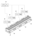
- FIG. 1 is a schematic diagram of a transport device according to an embodiment of the present invention
- FIG. FIG. 2 is a perspective view showing the internal structure of the module.
- FIG. FIG. 4 is a perspective view showing a scale of the slider.
- FIG. 1 is a configuration diagram of a collision prevention control system. 4 is a flowchart of the operation of the controller. 4 is a flowchart of the operation of the module controller.
- FIG. 2 is a diagram illustrating an interference region.
- FIG. 13 is a diagram illustrating the operation of the module controller (operation pattern (1)).
- FIG. 13 is a diagram illustrating the operation of the module controller (operation pattern (2)).
- FIG. 13 is a diagram illustrating the operation of the module controller (operation pattern (3)).
- FIG. 13 is a diagram illustrating the operation of the module controller (operation pattern (4)).
- FIG. 13 is a diagram illustrating the operation of the module controller (operation pattern (5)).
- FIG. 13 is a diagram illustrating the operation of the module controller (operation
- FIG. 1 is a schematic diagram of a conveying device 1 according to one embodiment of the present invention.
- the conveying device 1 has a conveying path 2 having a number of modules 3. Each module 3 is linear and connected end to end. A number of actuators 5 that perform work are arranged near the conveying path 2. The positions of the modules 3 facing the actuators 5 are identified by unique position numbers A, B, C, and D.
- the conveying path 2 is provided with a belt conveyor 6 and a removable module 7.
- the belt conveyor 6 moves the slider 4 in the opposite direction to the module 3.
- the removable module 7 transfers the slider 4 between the module 3 and the belt conveyor 6.
- the conveying path 2 may be arranged in a vertical plane and the slider 4 may be circulated vertically, or the conveying path 2 may be arranged in a horizontal plane and the slider 4 may be circulated horizontally.
- the conveying device 1 is controlled by a centralized controller 8.
- the centralized controller 8 is a general-purpose PLC (Programmable Logic Controller), a personal computer, etc.
- the centralized controller 8 includes a processor, memory, and a communication interface.
- the memory includes ROM and RAM.
- the centralized controller 8 For example, the centralized controller 8 generates a target position command to move the slider 4 to position number A and sends it to the controller 9.
- the module controller of the module 3 sends a signal to the centralized controller 8 via the controller 9 that the slider 4 has reached position number A.
- the centralized controller 8 receives this signal, it sends a command to the actuator controller 10 to start work.
- the centralized controller 8 moves the slider 4 to position number B.
- the centralized controller 8 moves the slider 4 to the attachment/detachment module 7 and the belt conveyor 6.
- the actuator 5 is controlled by an actuator controller 10.
- the actuator controller 10 is a PLC, a personal computer, etc.
- the actuator controller 10 includes a processor, a memory, and a communication interface.
- the centralized controller 8 and the controllers 9 are connected by a communication link 12 such as DeviceNet, EtherCAT, or EtherNET/IP.
- the centralized controller 8 and the actuator controllers 10 are similarly connected by a communication link 13.
- the controller 9 and the module controllers of the modules 3 are connected by a communication line 14 capable of synchronous communication such as RS485 or I2C.
- the controller 9 executes the configuration software 11 when the conveying device 1 is started up.
- the memory 36 (see FIG. 6) of the controller 9 stores machine coordinates (movement coordinates) corresponding to the unique position numbers A, B, C, and D.
- the memory 36 of the controller 9 also stores the speed, acceleration, jerk, etc., when the module controller of the module 3 creates the motion profile (speed curve) of the slider 4. (Module)
- the module 3 includes a stator 20 having a plurality of coils 21. As shown in FIG. 4, a plurality of stators 20 (four in this embodiment) are provided for one module 3.
- FIG. 2 shows one stator 20. Each stator 20 includes a plurality of sets (two sets in this embodiment) of coils 21 for the U, V, and W phases. Power is supplied to the stator 20 by a drive circuit 22. A power line (not shown) is connected to the drive circuit 22.
- the drive circuit 22 is a power converter such as a PWM inverter.
- the drive circuit 22 is controlled by a module controller 24.
- a plurality of drive circuits 22 (four in this embodiment) are provided for one module controller 24.
- the drive circuit 22 is arranged on a driver board 23 shown in FIG. 3.
- the module controller 24 is also arranged on the driver board 23 shown in FIG. 3.
- the module 3 is equipped with a linear guide 25 that smoothly guides the linear movement of the slider 4.
- the rail 26 of the linear guide 25 is attached to the base 28 of the module 3.
- the carriage 27 of the linear guide 25 is attached to the slider 4.
- the module 3 is provided with sensors 29 for detecting the identification ID and current position of the slider 4.
- the sensors 29 are Hall sensors, magnetic resistance sensors, etc.
- the sensors 29 are arranged on a sensor board 30.
- the sensors 29 are provided corresponding to each stator 20. In this embodiment, four sensors 29 are provided.
- the slider 4 includes a driving permanent magnet 31 that serves as a mover of a linear motor. As shown in Fig. 5, the slider 4 includes a scale 32 that is parallel to the driving permanent magnet 31. The sensor 29 detects the magnetic field of the scale 32 to detect the identification ID and the current position of the slider 4. (Collision Prevention Control System)
- FIG 6 shows a configuration diagram of a collision prevention control system.
- the collision prevention control system includes a controller 9 and a plurality of module controllers 24.
- the controller 9 is a computer such as a personal computer.
- the controller 9 includes a processor 35, a memory 36, and a communication interface 37.
- the memory 36 includes a ROM and a RAM.
- the processor 35 executes a program stored in the memory 36.
- the controller 9 may be a microcomputer or an electric circuit such as an FPGA (Field Programmable Gate Array) or an ASIC (Application Specific Integrated Circuit).
- the centralized controller 8 and the controller 9 are connected by the above-mentioned communication link 12.
- the controller 9 and the module controller 24 are connected by a communication line 14 such as RS485 or I2C.
- Adjacent module controllers 24 are also connected by a communication line 15 such as RS485 or I2C.
- the controller 9 converts the target position command (position numbers A, B, C, D) for the slider 4 received from the centralized controller 8 into a target position command (movement coordinates) and transmits the target position command for the slider 4 to all module controllers 24.
- the module controller 24 is a microcomputer.
- the module controller 24 includes a processor 38, a memory 39, a communication interface 40, and an interface circuit 41.
- the module controller 24 may be a computer such as a personal computer, or may be an electric circuit such as an FPGA or ASIC.
- the module controller 24 receives a target position command (movement coordinates) for the slider 4 from the controller 9.
- the module controller 24 of the module 3 in which the slider 4 exists creates a motion profile (speed curve, etc.) for the slider 4 based on this target position command, generates a movement command (position command and speed command, or position command), and controls the drive circuit 22.
- the module controller 24 switches the drive circuit 22.
- the module controller 24 of the other module 3 takes over the motion profile and controls the drive circuit 22 of the other module 3.
- the module controller 24 includes an interface circuit 41.
- the interface circuit 41 processes the output signal of the sensor 29 that detects the current position of the slider 4 so that it can be feedback-controlled.
- the interface circuit 41 also processes the output signal of the current sensor 42 that detects the current in the stator 20 so that it can be feedback-controlled.
- the processor 38 of the module controller 24 performs position control, speed control, and current control of the slider 4. That is, the processor 38 generates a speed command based on the deviation between the position command of the movement command and the current position detected by the sensor 29. Then, the processor 38 generates a current command based on the deviation between the speed command and the current speed detected by the sensor 29. Then, the processor 38 generates a voltage command based on the deviation between the current command and the current current detected by the current sensor 42.
- the drive circuit 22 converts DC power to AC power using switching elements based on the voltage command generated by the processor 38, and supplies the AC power to the stator 20. (Collision prevention control method)
- Figure 7 shows a flowchart of the operation of the controller 9.
- the controller 9 receives a target position command (position number A, B, C, D) from the centralized controller 8 (S1)
- the controller 9 converts the target position command (position number A, B, C, D) into a target position command (movement coordinates) and transmits the target position command (movement coordinates) to all module controllers 24 (S2).
- the controller 9 also transmits information such as speed, acceleration, and jerk to create a motion profile (speed curve) of the slider 4 to all module controllers 24.
- the controller 9 receives slider information from the module controller 24 of the module 3 in which the slider 4 exists (S3).
- the slider information includes the identification ID, current position, current speed, and interference area of the slider 4.
- the identification ID is a number for identifying the slider 4.
- the current position is the current position of the slider 4 detected by the sensor 29.
- the current speed is the current speed of the slider 4 detected by the sensor 29.
- the interference area is, in other words, an area where other sliders 4 are prohibited from entering. As shown in FIG. 9, the interference area is the distance until the slider 4 decelerates and stops.
- the interference area is defined by the positive side safe stop position Xcw in the traveling direction of the slider 4 and the negative side safe stop position Xccw in the opposite direction.
- the scan time travel distance is the distance that the slider 4 travels during a position update period of the controller 9.
- the scan time travel distance is determined as in Equation 2.
- Scan time travel distance (mm) number of sliders x ⁇ s x speed (mm/s)
- ⁇ is the time from when the controller 9 inquires of one of the module controllers 24 about slider information until when one of the module controllers 24 responds to the controller 9 with the slider information.
- the deceleration stop distance is the distance when the slider 4 immediately decelerates to a stop.
- the deceleration stop distance is determined as shown in Equation 3.
- Equation 3 an emergency stop deceleration that is greater than the deceleration used to create the motion profile (speed curve) is used.
- the slider size (+) (mm) is the length from the center of the slider 4 to the end of the slider 4 in the direction of travel.
- the slider size (+) uses the longer of the slider 4 or the pallet 16.
- a margin may or may not be provided.
- the negative side safe stop position Xccw is set to 0 when the slider 4 is moving in the cw direction or when the slider 4 is stopped.
- the negative side safe stop position Xccw is set in the same manner as in Equation 1.
- the positive side safe stop position Xcw is set to, for example, 0 when the slider 4 moves in the ccw direction or when the slider 4 is stopped.
- the controller 9 receives slider information from the module controller 24 of the module 3 in which the slider 4 exists (S3). Then, the controller 9 transmits the received slider information to all module controllers 24 (S4). This allows all module controllers 24 to share the slider information.
- the slider information sent from the controller 9 to the module controller 24 is represented in the table format of Table 1, for example.
- FIG 8 shows a flowchart of the operation of the module controller 24.
- the module controller 24 of the module 3 in which the slider 4 to be controlled is located receives slider information from the controller 9 (S11).
- the module controller 24 determines whether the slider 4 to be controlled, which is assumed to have moved to the target position, will interfere with the interference area of the adjacent slider 4 (the slider 4 ahead in the traveling direction) (S12). If there is no interference, the module controller 24 sets the target position A received from the controller 9 as the target position (S13) and creates a motion profile (speed curve) based on the target position A (S15).
- the module controller 24 changes the target position to a provisional target position A1 to avoid interference (S14), and creates a motion profile based on the provisional target position A1 (S15).
- the module controller 24 generates a movement command (position command and speed command, or position command) based on the motion profile, and controls the drive circuit 22 to feedback control the slider 4 to be controlled (S16).
- the operation of the module controller (S12) to (S15) will be explained in detail by dividing it into patterns.
- the current position of the slider 4A to be controlled is A
- the current position of the adjacent slider 4B received from the controller 9 is B.
- the interference area 18 (+) of slider 4B is the plus side safe stop position Xcw received from the controller 9.
- the interference area 18 (-) of slider 4B is determined from the minus side safe stop position Xccw and slider size (-) received from the controller 9.
- the plus side safe stop position Xcw, minus side safe stop position Xccw, and slider size (+) (-) are stored in the memory 39 of the module controller 24.
- the symbols 19 (+) (-) indicate the slider size (+) (-) of slider 4A.
- the module controller 24 changes the target position from target position A received from the controller 9 to provisional target position A1 to avoid interference. Then, based on provisional target position A1, the velocity curve 17 is changed to velocity curve 17-1, shown by the dashed line in FIG. 11(a).
- the velocity curve 17-1 is updated at a predetermined update period (for example, 1 ms). As shown in FIG. 11(b), after a predetermined time has elapsed, when the slider 4B moves to the current position B shown in FIG. 11(b), the slider 4A will no longer interfere with the slider 4B even if it moves to the target position A. At this time, the module controller 24 resets the target position to the target position A received from the controller 9, and returns the velocity curve 17-1 to the original velocity curve 17. As a result, in this case, the operation of the slider 4A is not affected by the slider 4B.
- a predetermined update period for example, 1 ms
- Figures 12(a) and (b) show an example in which slider 4B is stopped.
- the module controller 24 changes target position A of slider 4A to provisional target position A1 to avoid the interference. Then, based on provisional target position A1, the velocity curve 17 is changed to velocity curve 17-1, shown by the dashed line in Figure 12(a).
- the slider 4B remains stopped even after a predetermined time has elapsed.
- the module controller 24 continues to hold the provisional target position A1 and stops the slider 4A at the provisional target position A1.
- Figures 13(a) and (b) show an example of slider 4B operating at a low speed.
- the module controller 24 changes target position A to provisional target position A1 to avoid the interference. Then, based on provisional target position A1, the speed curve 17 is changed to speed curve 17-1, shown by the dashed line in Figure 13(a).
- the module controller 24 changes the provisional target position A1 to a new provisional target position A2 and generates a speed curve 17-2. At this time, slider 4A repeatedly accelerates and decelerates until it reaches the same speed as slider 4B.
- Figures 14(a) and (b) show an example of slider 4B moving at high speed.
- the module controller 24 changes target position A to provisional target position A1 to avoid the interference. Then, based on provisional target position A1, the velocity curve 17 is changed to velocity curve 17-1, shown by the dashed line in Figure 14(a).
- the module controller 24 changes the provisional target position A1 to a new provisional target position A2 in accordance with the movement of slider 4B, and generates a new velocity curve 17-2.
- the new velocity curve 17-2 becomes closer to the original velocity curve 17.
- FIG. 15(a), (b), and (c) show an example in which slider 4A and slider 4B are moving facing each other.
- Slider 4A is controlled by the module controller 24 of the module 3 in which slider 4A is present.
- Slider 4B is controlled by the module controller 24 of the module 3 in which slider 4B is present.
- FIG. 15(a) at the start of the operation, slider 4A and slider 4B are separated. Slider 4A moves based on a velocity curve 33, and slider 4B moves based on a velocity curve 34.
- neither slider 4A nor slider 4B decelerates until the interference region 18 of slider 4A and the interference region 18 of slider 4B overlap.
- the module controller 24 of the module 3 in which the slider 4A exists changes the target position A to a provisional target position A1 that avoids interference, and changes the speed curve 33 to a speed curve 33-1 shown by a dashed line in Figure 15(c) based on the provisional target position A1. Then, the slider 4A is decelerated and stopped at an emergency stop deceleration that is greater than the deceleration when the sliders 4A and 4B move in the same direction.
- the module controller 24 of the module 3 in which the slider 4B exists changes the target position B to a provisional target position B1, changes the speed curve 34 to a speed curve 34-1, and decelerates and stops the slider 4B at the same emergency stop deceleration as the slider 4A. This makes it possible to prevent the sliders 4A and 4B from colliding with each other. When stopped, the slider 4A and the slider 4B are separated by a margin x 2. (effect)
- the control for collision prevention is distributed to the module controllers 24 of the modules 3 in which the sliders 4 to be controlled are located, the calculation load on the controller 9 and the centralized controller 8 can be reduced. Also, if a module controller 24 receives slider information from other module controllers 24 in distant locations via multiple module controllers 24, it takes time to receive the slider information. By having a module controller 24 receive slider information from other module controllers 24 via the controller 9, the time it takes to receive the slider information can be shortened.
- the slider information includes the identification ID, current position, and interference area of the slider 4, enabling a variety of controls to prevent collisions.
- the module controller 24 changes the target position of the slider 4 to the provisional target position to avoid the interference, so that the slider 4 to be controlled is not stopped unnecessarily, and the throughput of the conveying device 1 is improved.
- the controlled slider 4 and an adjacent slider 4 move in directions toward each other, the controlled slider 4 is decelerated and stopped at an emergency stop deceleration that is greater than the deceleration when they move in the same direction, so that collision between the two sliders 4 can be safely prevented.
- the interference area includes the deceleration and stopping distance until the slider 4 decelerates and stops, so collisions between the two sliders 4 when they move toward each other can be safely prevented.
- the interference region includes the scan time movement distance that the slider 4 moves during the position update period of the controller 9, so collisions between the two sliders 4 moving in directions toward each other can be safely prevented.
- the controller 9 transmits the target position command for the slider 4 received from the centralized controller 8 to the module controller 24, thereby reducing the calculation load on the centralized controller 8.
- the module controller of the module in which the slider to be controlled is located may calculate the distance between the slider to be controlled and an adjacent slider based on the slider's identification ID and current position information, and stop the slider to be controlled when this distance is equal to or less than a preset threshold.
- four drive circuits are provided for one module controller, but one drive circuit may be provided for one module controller.
- the centralized controller and the controller are separate, but the centralized controller and the controller may be integrated and the controller functions may be incorporated into the centralized controller.
Landscapes
- Engineering & Computer Science (AREA)
- Power Engineering (AREA)
- Control Of Conveyors (AREA)
- Numerical Control (AREA)
- Control Of Linear Motors (AREA)
Abstract
Description
(搬送装置)
(モジュール)
(衝突防止制御システム)
(衝突防止制御方法)
(式1)
プラス側干渉領域Xcw=スキャンタイム移動距離(mm)+減速停止距離(mm)+スライダサイズ(+)(mm)+マージン(mm)
(式2)
スキャンタイム移動距離(mm)=スライダ台数×αμs×速度(mm/s)
ここで、αは、コントローラ9が1台のモジュールコントローラ24にスライダ情報を問い合わせて、1台のモジュールコントローラ24がコントローラ9にスライダ情報を回答するまでの時間である。
(式3)
減速停止距離(mm)=(減速度(mm/s2)×0.5+速度(mm/s))×速度(mm/s)/減速度(mm/s2)
式3の減速度には、運動プロファイル(速度曲線)を作成するときの減速度よりも大きい緊急停止減速度を使用する。

(効果)
Claims (8)
- 複数のモジュールを有する搬送経路を複数のスライダが移動する搬送装置に用いられる衝突防止制御システムであって、
コントローラと、
複数のモジュールのドライブ回路を制御する複数のモジュールコントローラと、を備え、
前記スライダが存在するモジュールのモジュールコントローラが前記スライダの少なくとも識別IDと現在位置を含むスライダ情報を前記コントローラに送信し、
前記コントローラが前記スライダ情報を前記複数のモジュールコントローラに送信し、
制御対象のスライダが存在するモジュールのモジュールコントローラが、隣接するスライダとの衝突を防止するように制御対象のスライダを制御する衝突防止制御システム。 - 前記スライダ情報は、前記スライダの識別ID、現在位置及び干渉領域を含むことを特徴とする請求項1に記載の衝突防止制御システム。
- 前記モジュールコントローラは、目標位置まで移動したと仮定した制御対象のスライダが隣り合うスライダの干渉領域と干渉するとき、干渉を回避するように制御対象のスライダの目標位置を暫定目標位置に変化させることを特徴とする請求項2に記載の衝突防止制御システム。
- 前記モジュールコントローラは、制御対象のスライダと隣接するスライダが互いに向かい合う方向に移動するとき、これらが同一方向に移動するときの減速度よりも大きい緊急停止減速度で制御対象のスライダを減速停止させることを特徴とする請求項1又は2に記載の衝突防止制御システム。
- 前記干渉領域は、前記スライダが減速して停止するまでの減速停止距離を含むことを特徴とする請求項2又は3に記載の衝突防止制御システム。
- 前記干渉領域は、前記コントローラの位置更新周期の間に前記スライダが移動するスキャンタイム移動距離を含むことを特徴とする請求項5に記載の衝突防止制御システム。
- 前記コントローラが、集中コントローラから受信したスライダの目標位置指令を前記モジュールコントローラに送信することを特徴とする請求項1又は2に記載の衝突防止制御システム。
- 複数のモジュールを有する搬送経路を複数のスライダが移動する搬送装置に用いられる衝突防止制御方法であって、
前記搬送装置が、コントローラと、複数のモジュールのドライブ回路を制御する複数のモジュールコントローラと、を備え、
前記スライダが存在するモジュールのモジュールコントローラが前記スライダの少なくとも識別情報と位置情報を含むスライダ情報を前記コントローラに送信し、
前記コントローラが前記スライダ情報を前記複数のモジュールコントローラに送信し、
制御対象のスライダが存在するモジュールのモジュールコントローラが、隣接するスライダとの衝突を防止するように制御対象のスライダを制御する衝突防止制御方法。
Priority Applications (3)
| Application Number | Priority Date | Filing Date | Title |
|---|---|---|---|
| DE112024002588.9T DE112024002588T5 (de) | 2023-06-16 | 2024-05-10 | Kollisionsverhinderungssteuerungssystem und -Verfahren |
| CN202480036189.1A CN121219955A (zh) | 2023-06-16 | 2024-05-10 | 碰撞防止控制系统以及方法 |
| KR1020267000666A KR20260025365A (ko) | 2023-06-16 | 2024-05-10 | 충돌 방지 제어 시스템 및 방법 |
Applications Claiming Priority (2)
| Application Number | Priority Date | Filing Date | Title |
|---|---|---|---|
| JP2023098880A JP2024179758A (ja) | 2023-06-16 | 2023-06-16 | 衝突防止制御システム及び方法 |
| JP2023-098880 | 2023-06-16 |
Publications (1)
| Publication Number | Publication Date |
|---|---|
| WO2024257518A1 true WO2024257518A1 (ja) | 2024-12-19 |
Family
ID=93851847
Family Applications (1)
| Application Number | Title | Priority Date | Filing Date |
|---|---|---|---|
| PCT/JP2024/017361 Ceased WO2024257518A1 (ja) | 2023-06-16 | 2024-05-10 | 衝突防止制御システム及び方法 |
Country Status (6)
| Country | Link |
|---|---|
| JP (1) | JP2024179758A (ja) |
| KR (1) | KR20260025365A (ja) |
| CN (1) | CN121219955A (ja) |
| DE (1) | DE112024002588T5 (ja) |
| TW (1) | TW202501191A (ja) |
| WO (1) | WO2024257518A1 (ja) |
Citations (1)
| Publication number | Priority date | Publication date | Assignee | Title |
|---|---|---|---|---|
| JP2022184755A (ja) * | 2021-05-31 | 2022-12-13 | ベーウントエル・インダストリアル・オートメイション・ゲゼルシャフト・ミト・ベシュレンクテル・ハフツング | 衝突監視装置を有する搬送システム及び当該搬送システムを稼働させるための方法 |
Family Cites Families (1)
| Publication number | Priority date | Publication date | Assignee | Title |
|---|---|---|---|---|
| CN111035394B (zh) | 2014-09-02 | 2023-06-30 | 苹果公司 | 身体活动和健身监视器 |
-
2023
- 2023-06-16 JP JP2023098880A patent/JP2024179758A/ja active Pending
-
2024
- 2024-05-10 DE DE112024002588.9T patent/DE112024002588T5/de active Pending
- 2024-05-10 CN CN202480036189.1A patent/CN121219955A/zh active Pending
- 2024-05-10 KR KR1020267000666A patent/KR20260025365A/ko active Pending
- 2024-05-10 WO PCT/JP2024/017361 patent/WO2024257518A1/ja not_active Ceased
- 2024-05-16 TW TW113118036A patent/TW202501191A/zh unknown
Patent Citations (1)
| Publication number | Priority date | Publication date | Assignee | Title |
|---|---|---|---|---|
| JP2022184755A (ja) * | 2021-05-31 | 2022-12-13 | ベーウントエル・インダストリアル・オートメイション・ゲゼルシャフト・ミト・ベシュレンクテル・ハフツング | 衝突監視装置を有する搬送システム及び当該搬送システムを稼働させるための方法 |
Also Published As
| Publication number | Publication date |
|---|---|
| TW202501191A (zh) | 2025-01-01 |
| KR20260025365A (ko) | 2026-02-24 |
| JP2024179758A (ja) | 2024-12-26 |
| CN121219955A (zh) | 2025-12-26 |
| DE112024002588T5 (de) | 2026-04-30 |
Similar Documents
| Publication | Publication Date | Title |
|---|---|---|
| US10994943B2 (en) | Method for operating a long stator linear motor with transport units and collision monitoring | |
| EP3501880B1 (en) | Linear drive system having central, distributed and group control | |
| EP3537247B1 (en) | Method and apparatus for coordinating external device motion with motion of independent movers in a linear drive system | |
| EP2599186B1 (en) | System and method for providing power to a moving element | |
| JP5334709B2 (ja) | 被印刷物のためのセグメント化された搬送系の少なくとも2つのブリッジを個別化する方法 | |
| US8794426B2 (en) | Pallet-based position adjustment system and method | |
| US12421056B2 (en) | Transport system and method for operating a transport system with collision monitoring | |
| US10826370B2 (en) | Method for operating a long stator linear motor with switch | |
| US20220306406A1 (en) | Method for operating a transport system in the form of a long-stator linear motor | |
| EP3301809B1 (en) | Method and apparatus for interleaved switching of track segments in a motion control system | |
| US20210370777A1 (en) | System and Method for Collision Prevention in a Linear Motion System | |
| US12195062B2 (en) | System and method for controlling movers in an independent cart system during heavy traffic | |
| US20190369612A1 (en) | Motor control device | |
| US20230365000A1 (en) | Method of operating a transport system and transport system | |
| JP2024179758A (ja) | 衝突防止制御システム及び方法 | |
| JP2014047022A (ja) | 移動体の制御方法 | |
| KR102447060B1 (ko) | 부서지기 쉬운 물체를 운송하기 위한 운송 장치 및 운송 방법 | |
| JP4170567B2 (ja) | 工作機械の移動装置および工作機械の移動装置の制御方法 | |
| CN108227638B (zh) | 数值控制装置 | |
| JP2009181149A (ja) | 搬送装置のモーション制御装置 | |
| KR20210055295A (ko) | 이송 장치 | |
| JP4596806B2 (ja) | 駆動制御装置及び駆動制御方法 | |
| JP2001002207A (ja) | 荷移載装置 | |
| JP2004216429A (ja) | タンデムプレスラインの異常処理システム | |
| JP2004195487A (ja) | フィーダの非常退避方法 |
Legal Events
| Date | Code | Title | Description |
|---|---|---|---|
| 121 | Ep: the epo has been informed by wipo that ep was designated in this application |
Ref document number: 24823140 Country of ref document: EP Kind code of ref document: A1 |
|
| ENP | Entry into the national phase |
Ref document number: 1020267000666 Country of ref document: KR Free format text: ST27 STATUS EVENT CODE: A-0-1-A10-A15-NAP-PA0105 (AS PROVIDED BY THE NATIONAL OFFICE) |
|
| WWE | Wipo information: entry into national phase |
Ref document number: 1020267000666 Country of ref document: KR |
|
| WWE | Wipo information: entry into national phase |
Ref document number: 112024002588 Country of ref document: DE |
|
| WWP | Wipo information: published in national office |
Ref document number: 1020267000666 Country of ref document: KR |
|
| WWP | Wipo information: published in national office |
Ref document number: 112024002588 Country of ref document: DE |
|
| 122 | Ep: pct application non-entry in european phase |
Ref document number: 24823140 Country of ref document: EP Kind code of ref document: A1 |