WO2024257510A1 - 放射線撮影システム、放射線撮影システムの撮影支援方法及びプログラム - Google Patents
放射線撮影システム、放射線撮影システムの撮影支援方法及びプログラム Download PDFInfo
- Publication number
- WO2024257510A1 WO2024257510A1 PCT/JP2024/017196 JP2024017196W WO2024257510A1 WO 2024257510 A1 WO2024257510 A1 WO 2024257510A1 JP 2024017196 W JP2024017196 W JP 2024017196W WO 2024257510 A1 WO2024257510 A1 WO 2024257510A1
- Authority
- WO
- WIPO (PCT)
- Prior art keywords
- control unit
- imaging
- fpd
- radiation
- information
- Prior art date
- Legal status (The legal status is an assumption and is not a legal conclusion. Google has not performed a legal analysis and makes no representation as to the accuracy of the status listed.)
- Ceased
Links
Images















Classifications
-
- A—HUMAN NECESSITIES
- A61—MEDICAL OR VETERINARY SCIENCE; HYGIENE
- A61B—DIAGNOSIS; SURGERY; IDENTIFICATION
- A61B6/00—Apparatus or devices for radiation diagnosis; Apparatus or devices for radiation diagnosis combined with radiation therapy equipment
Definitions
- the present invention relates to a radiography system, a radiography system imaging support method, and a program.
- Radiation imaging systems have been used that include a radiation irradiation device that generates radiation and a radiation imaging device that receives radiation and generates radiation image data.
- Radiation imaging includes a moving image imaging technique in which a subject is imaged continuously at regular intervals to obtain a plurality of frame images.
- video imaging There are two types of video imaging: “dynamic” imaging, in which the timing of radiation exposure and the timing of generating a radiographic image must be synchronized, and “fluoroscopic” imaging, in which only the timing of the start and end of imaging must be synchronized. For this reason, the radiation imaging systems of Patent Documents 1 and 2 perform a synchronization process for matching the timing of image generation by the radiation imaging device with the irradiation by the radiation irradiation device.
- the console recognizes the synchronization state, but there is no mention of making the synchronization state clear to the imaging technician.
- the imaging device displays on the display unit whether or not the signal is synchronized.
- the display screen is only displayed at a timing when the user is not likely to be looking at the display unit in the workflow during imaging. For this reason, there is room for improvement in calling the attention of imaging technicians.
- the objective of the present invention is to more effectively draw the user's attention by informing them at an appropriate time and in an appropriate manner whether or not the radiographic imaging device is synchronized.
- the radiation imaging system of the present invention comprises: a radiation image capturing device that captures moving images in synchronization with the radiation irradiation device; a presentation unit that presents information regarding a synchronization state of the radiation image capturing device with respect to the radiation irradiation device; A control unit that controls the presentation unit; Equipped with The control unit determines the synchronization status of the radiographic imaging device at at least one of the following times: when the radiographic imaging device is stored in a storage unit, when the radiographic imaging device is removed from the storage unit, when the radiographic imaging device to perform imaging is selected, when the control unit acquires imaging order information from an external device, when imaging order information is added, or when imaging order information is selected by a user, and causes the presentation unit to present information regarding the synchronization status of the radiographic imaging device.
- the imaging support method for the radiation imaging system of the present invention comprises the steps of: 1.
- An imaging support method for a radiation imaging system having a radiation image capturing device that captures a moving image in synchronization with a radiation irradiation device, a presentation unit that presents information regarding a synchronization state of the radiation image capturing device with respect to the radiation irradiation device, and a control unit that controls the presentation unit,
- the synchronization status of the radiographic imaging device is determined at least one of the following times: when the radiographic imaging device is stored in a storage unit, when the radiographic imaging device is removed from the storage unit, when the radiographic imaging device to perform imaging is selected, when the control unit acquires imaging order information from an external device, when imaging order information is added, or when imaging order information is selected by a user, and information regarding the synchronization status of the radiographic imaging device is presented on the presentation unit.
- the program of the present invention comprises: a radiation imaging device that captures moving images in synchronization with a radiation irradiation device, a presentation unit that presents information on a synchronization state of the radiation imaging device with respect to the radiation irradiation device, and a control unit that controls the presentation unit;
- the synchronization status of the radiographic imaging device is determined at least at one of the following times: when the radiographic imaging device is stored in a storage unit, when the radiographic imaging device is removed from the storage unit, when the radiographic imaging device to perform imaging is selected, when the control unit acquires imaging order information from an external device, when imaging order information is added, or when imaging order information is selected by a user, and a function is realized that causes the presentation unit to present information relating to the synchronization status of the radiographic imaging device.
- the present invention makes it possible to properly inform the user of whether or not the radiographic imaging device is synchronized, and to more effectively draw attention to the situation.
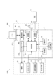
- FIG. 1 is a schematic configuration diagram showing a radiation imaging system according to an embodiment of the present invention
- FIG. 2 is a block diagram showing the configuration of a medical cart.
- FIG. 13 is a diagram showing an example of a display screen of examination information displayed on a display unit.
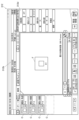
- FIG. 13 is a diagram showing an example of an examination screen of selected examination information.
- FIG. 13 is a diagram showing an examination screen on which radiography order information is added.
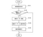
- 13 is a flowchart of a synchronization process.
- 13 is a flowchart showing a synchronization state presentation process (1).
- 13 is a display example in which an icon in an image display area of the examination screen is highlighted.
- FIG. 13 is a diagram showing an example of a positive screen.
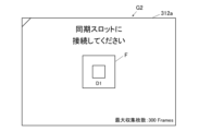
- FIG. 13 is a diagram showing an example of a negative screen.
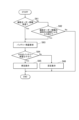
- FIG. 13 is a flowchart showing a synchronization state presentation process (2).
- 13 is a flowchart showing a synchronization state presentation process (3).
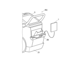
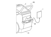
- FIG. 13 is an explanatory diagram showing a state in which the FPD is stored in a storage section.
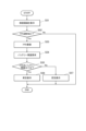
- 13 is a flowchart showing a synchronization state presentation process (4).
- FIG. 13 is an explanatory diagram showing a state in which the FPD is being removed from the storage section.
- FIG. 13 is a diagram showing an example of a negative screen.
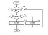
- 13 is a flowchart showing a synchronization state presentation process (5).
- 11 is a flowchart showing a battery remaining capacity presentation process (1).
- FIG. 13 is a diagram showing an example of a negative screen.
- 13 is a flowchart showing a battery remaining capacity presentation process (2).
- FIG. 13 is a flowchart showing a battery remaining capacity presentation process (3).
- FIG. 2 is a diagram showing a first screen.
- FIG. 2 is a diagram showing a second screen.
- 13 is a flowchart showing a battery remaining capacity presentation process (4).
- 13 is a flowchart showing a battery remaining capacity presentation process (5).
- 13 is a flowchart showing equipment information presentation processing (1).
- FIG. 13 is a diagram showing an example of a device information presentation screen.
- 13 is a flowchart showing equipment information presentation processing (2).
- 13 is a flowchart showing a device information presentation process (3).
- 13 is a flowchart showing a device information presentation process (4).
- Figure 1 is a schematic diagram showing the configuration of a radiography system 100.
- Figure 2 is a block diagram showing the configuration of a mobile cart RC.
- the radiation imaging system 100 is installed in a medical facility such as a hospital.
- a user U such as an imaging technician at a medical facility, makes rounds on patients.
- the user U moves to the destination, such as a ward or an operating room, where the patient is located, together with the radiation imaging system 100, and performs radiation imaging on the patient.
- the destination such as a ward or an operating room
- the radiation imaging system 100 performs radiation imaging on the patient.
- a case is shown in which the destination is a ward, and a bed B is installed in the ward.
- a patient S who is a subject, is subjected to radiation imaging while lying on the bed B, for example.
- the radiation imaging system 100 includes an FPD 1, which is a radiation image capturing device, and a mobile radiation irradiation device, a medical cart RC.
- FPD is an abbreviation for Flat Panel Detector.
- the FPD 1 and the medical cart RC can communicate with each other, for example, via wireless communication.
- the radiation imaging system 100 has one or more FPDs 1.
- the radiation imaging system 100 has at least one FPD 1 capable of both still image capture and moving image capture. Furthermore, the radiation imaging system 100 may also have an FPD 1 capable of only still image capture.
- Shooting a still image means acquiring an image of the subject S in response to a single shooting operation.
- the FPD and the radiation irradiation device are synchronized in still image shooting as well, the synchronization is performed immediately before irradiation (at least after the irradiation button is pressed).
- the synchronization in dynamic imaging which will be described later, differs from that in still image shooting in that it is performed before the irradiation button is pressed.
- synchronization of still image capture is a series of sequential request and response operations, in which the following operations are performed for each irradiation: irradiation start request ⁇ FPD preparation for imaging - completion ⁇ irradiation permission ⁇ irradiation ⁇ readout.
- synchronization of dynamic image capture is a non-sequential operation in which sequential exchanges are not performed between the radiation irradiation device and the FPD for each irradiation of radiation.
- synchronization of still image capture and synchronization of dynamic image capture differ.
- the term "synchronization" does not include “synchronization of still image capture” but refers to synchronization of video capture.
- Moving image capture refers to capturing a plurality of images of the subject S by capturing consecutive images of the subject S in response to a single capture operation.
- moving image capture methods a method of capturing images synchronously with pulse irradiation in which radiation such as X-rays is irradiated repeatedly at predetermined time intervals in a pulsed form is called dynamic imaging.
- dynamic photography may be referred to as capturing dynamic images.
- the FPD 1 is a device that generates radiation image data corresponding to the radiation R emitted from the radiation generating device 2 .
- the FPD 1 is configured in a panel shape and is portable.
- the user U can use the FPD 1 by mounting it on an imaging stand.
- the user U can use the FPD 1 by horizontally disposing it between the subject S and a bed B. In this case, the subject S is in a supine position on the bed.
- the user U can also use the FPD 1 by disposing it between the subject S and the bed as shown in FIG. 1.
- the FPD 1 includes, for example, a scintillator, a PD, a TFT switch, and the like.
- PD is an abbreviation for Photo Diode.
- TFT is an abbreviation for Thin Film Transistor.
- the scintillator, PD, TFT switch, and the like are not illustrated.
- the scintillator converts incident radiation R into light.
- the PDs are arranged in a matrix corresponding to the pixels.
- the TFT switches are arranged corresponding to each PD.
- the incident radiation R is converted into light by the scintillator and enters the PD.
- the PD that receives the incident radiation R accumulates the radiation R as an electric charge for each pixel.
- the electric charge accumulated in the PD flows out from the TFT switch to the signal line.
- the electric charge is amplified and A/D converted into radiation image data.
- the radiation image data is output to the mobile cart RC.
- the FPD 1 is an indirect conversion type. However, the FPD 1 may be configured as a direct conversion type that directly converts the radiation R into an electrical signal.
- RIS Radiology Information Systems
- the RIS 40 is a system that manages examinations using radiation equipment, treatment reservations, and examination results.
- the mobile car RC may be capable of communicating with an electronic medical record system and consoles of other radiography systems via the communication network N.
- the mobile car RC may also be capable of communicating with other mobile cars, PACS, other examination devices, bed systems, etc.
- PACS is an abbreviation for Picture Archiving and Communication System.
- the communication network N is wireless, but may be wired.
- the medical cart RC has a radiation generator 2 and a console 3.
- the radiation generating device 2 comprises a device body 21, an irradiation instruction switch 22, a tube 23, a tube support section 24, and a collimator 25.
- the radiation generating device 2 further comprises a generator 213, a storage section 26 for the FPD 1, an optical imaging section 28, and a second display section 29.
- the radiation generating device 2 can be moved by wheels 27 provided on the housing of the device body 21.
- the irradiation instruction switch 22 outputs an operation signal to the device body 21 by operation of the user U. Note that in FIG. 1, the irradiation instruction switch 22 sends an operation signal to the device body 21 via a wired connection. However, the irradiation instruction switch 22 may also send an operation signal to the device body 21 wirelessly.
- the generator 213 receives an imaging instruction signal from the control unit 211, which will be described later, by operating the irradiation instruction switch 22.
- the generator 213 applies a voltage to the tube 23 according to the imaging conditions that have been set in advance.
- the generator 213 also passes a current to the tube 23 according to the imaging conditions.
- the tube 23 generates radiation R (such as X-rays) by applying voltage and current from the generator 213. At this time, the tube 23 generates radiation R at a dose according to the preset imaging conditions and in a manner according to the imaging conditions. The tube 23 irradiates radiation R from an irradiation port.
- radiation R such as X-rays
- the tube support 24 is an arm that supports the tube 23 .
- the tube support 24 has a support part 241 extending upward from the device body 21, and a support part 242 extending forward from an upper part of the support part 241.
- the tip of the support part 242 supports the tube 23.
- the tube support part 24 has a joint mechanism (not shown).
- the tube support part 24 can move the tube 23 in the X-axis direction, the Y-axis direction, and the Z-axis direction by using the joint mechanism.
- the X-axis direction is the left-right direction on the paper surface of FIG. 1.
- the X-axis direction corresponds to the front-rear direction of the radiation generating device 2.
- the Y-axis direction is a direction perpendicular to the paper surface of FIG. 1.
- the Y-axis direction corresponds to the width direction of the radiation generating device 2.
- the Z-axis direction is the up-down direction on the paper surface of FIG. 1.
- the Z-axis direction is the vertical direction.
- the tube support part 24 can rotate the tube 23 around rotation axes parallel to the X-axis, Y-axis, and Z-axis by using the joint mechanism. This allows the tube support part 24 to change the irradiation direction of the radiation R.
- the collimator 25 is attached to an irradiation port of the housing of the bulb 23.
- the collimator 25 focuses the radiation R.
- the collimator 25 causes the irradiation field of the radiation R to have a preset rectangular shape.
- the collimator 25 also includes a lamp button (not shown). When the user operates the lamp button, the collimator 25 irradiates a range that is to become the irradiation field of the radiation R with visible light.
- the optical photographing unit 28 has an optical system such as a lens, and an image pickup element such as a CCD, a CMOS, etc.
- CCD is an abbreviation for Charge Coupled Device
- CMOS is an abbreviation for Complementary Metal Oxide Semiconductor.
- the optical photographing unit 28 is provided in the housing of the collimator 25. Note that the optical photographing unit 28 may be provided in the housing of the bulb 23 or in the bulb support unit 24.
- the optical photographing unit 28 optically photographs the subject S as a subject with visible light and generates optical image data under the control of the control unit 211. Furthermore, the optical photographing unit 28 outputs the optical image data to the control unit 211, etc.
- the optical photographing unit 28 optically photographs the subject S and generates optical image data of a still image or dynamic image (such as a live image).
- the second display unit 29 is configured with an LCD, an EL display, etc.
- LCD is an abbreviation for Liquid Crystal Display.
- EL is an abbreviation for Electro-Luminescence.
- the second display unit 29 displays various information in accordance with the display information, which is input to the second display unit 29 from the control unit 211, which will be described later.
- the second display unit 29 is provided on the outside of the housing of the bulb 23. It is assumed that the bulb 23 is oriented vertically downward. In this case, the second display unit 29 is attached to the cover of the bulb 23 so as to face forward (to the right in FIG. 1 ).
- the storage unit 26 is provided on the rear surface of the apparatus body 21 and stores the FPD 1 when not in use.
- the storage unit 26 can store one or a plurality of FPDs 1.
- the storage unit 26 has the following configuration.
- the storage unit 26 has three slots capable of storing the FPD 1. Each slot has a connector therein that can be connected to a connector (not shown) that the FPD 1 has. Each connector is connected to a power supply circuit 262.
- the power supply circuit 262 can charge the battery of the FPD 1 through the connector.
- only one of the three slots is provided with a connector 261 having a communication function for performing a synchronous process with the radiation generation device 2 for the FPD 1. In Fig. 2, only the connector 261 having the communication function is illustrated.
- the console 3 is configured by a PC, a mobile terminal, or a dedicated device.
- PC is an abbreviation for Personal Computer.
- the console 3 is mounted on the top of the device main body 21.
- the console 3 manages various types of information required for radiographic imaging. Furthermore, the console 3 acquires radiation image data generated by the FPD 1.
- the console 3 can store the radiation image data therein and transmit it to another external device (such as a PACS).
- the device main body 21 and the console 3 are illustrated as being housed in a single housing and integrated together.
- the device main body 21 and the console 3 may be configured as separate bodies.
- the console 3 includes a control unit, a storage unit, a communication unit, a display unit 31, an operation unit 32, and an audio output unit 33.
- the control unit, storage unit, and communication unit of the console 3 are respectively served by the control unit 211, storage unit 212, and communication unit 214 of the radiation generating device 2.
- the console 3 may be configured to include a dedicated control unit, storage unit, and communication unit. In that case, it is preferable that the control unit 211 of the radiation generating device 2 and the control unit of the console 3 are capable of communicating with each other via a wire.
- the control unit 211 is connected to each unit of the radiation generating device 2 except for the bulb 23 so as to be able to communicate with each other.
- the control unit 211 is composed of a CPU, a RAM, etc.
- the CPU reads out various programs stored in the storage unit 212 and loads them in the RAM.
- the CPU then executes various processes in cooperation with the loaded programs. As a result, the CPU controls each part of the radiation generation device 2 and the console 3.
- the storage unit 212 is configured from a non-volatile memory, a HDD, or the like.
- the storage unit 212 stores various programs executed by the control unit 211, and various data such as parameters and files required for executing the programs.
- the storage unit 212 stores programs for executing various processes described below.
- the memory unit 212 also stores various information related to the FPD 1 registered for the medical cart RC. This information includes information on a synchronization state and an expiration date, which will be described later, of the registered FPD 1. This information also includes information indicating for which imaging order, which will be described later, the FPD 1 is used.
- the storage unit 212 also stores examination information and radiography order information for the medical cart RC, which will be described later.
- the communication unit 214 is composed of a communication module and the like.
- the communication unit 214 is capable of transmitting and receiving various signals and various data to and from an external device such as the wirelessly connected FPD 1 or the RIS 40 connected via the communication network N.
- the display unit 31 is configured with an LCD, an EL display, or the like.
- the display unit 31 displays various types of information according to the display information input from the control unit 211 .
- the operation unit 32 includes, for example, one or more of a keyboard, a pointing device, a touch panel, etc.
- the touch panel is integrally formed with the display screen of the display unit 31.
- the touch panel may also be integrally formed with the display screen of the second display unit 29.
- the operation unit 32 accepts operation input from the user U and outputs the operation information to the control unit 211 .
- the audio output unit 33 includes an amplifier, a speaker, etc.
- the audio output unit 33 outputs audio in response to audio information input from the control unit 211.
- the console 3 can acquire examination information for the medical cart RC from the RIS 40 through the communication unit 214.
- new examination information and radiography order information may be added to the console 3 from the RIS 40.
- FIG. 3 shows an example of a display screen 311 of examination information displayed on the display unit 31.
- the control unit 211 displays one or more pieces of examination information in a list 311a on the display screen 311.
- the examination information is information about a scheduled examination.
- Each piece of examination information includes a patient ID, a patient name, an imaging region, a scheduled imaging date and time, a size of the FPD 1 corresponding to imaging, imaging conditions, and the like.
- the control unit 211 accepts a selection input of the examination information displayed in the list 311 a from the user via the operation unit 32 .
- the control unit 211 displays an examination screen 312 for the selected examination information.
- FIG. 4 shows an example of an examination screen 312 for selected examination information.
- the examination screen 312 displays an image display area 312a, a patient information display area 312b, an imaging order display area 312c, and a reading condition setting button 312d.
- an icon F indicating one or more FPDs 1 registered in the console 3 is displayed.
- Each FPD 1 used in a medical facility is assigned a unique serial number.
- a user U can register one or more FPDs 1 to be used for radiography by inputting the serial number from the operation unit 32.
- the control unit 211 requests and acquires information such as specifications of the registered FPD 1 from the FPD 1 and the RIS 40.
- the acquired information such as specifications of the FPD 1 includes, for example, the size that can be photographed, whether dynamic imaging is supported, etc.
- the acquired information such as specifications of the FPD 1 can also be input by the user U from the operation unit 32.
- the control unit 211 may periodically communicate with each registered FPD 1 via the communication unit 214. In this case, the control unit 211 determines whether wireless communication is possible with each FPD 1. For example, an FPD 1 placed in an area of the medical facility away from the medical cart RC cannot perform wireless communication. The control unit 211 may control the display unit 31 so as not to display the icon F of such an FPD 1 in the image display area 312a.
- the patient information display area 312b is an area for displaying patient information of the subject S who is the subject of the examination.
- the reading condition setting button 312d is a button for setting reading conditions at the time of photographing.
- the settable reading conditions include whether or not to execute automatic reading, the reading size at the time of photographing, the reading direction (vertical and horizontal), the reading position, the resolution, and the like.
- the imaging order display area 312c displays an icon C of the imaging order included in the selected examination information.
- the imaging order indicates the radiographic imaging to be performed in the examination whose examination information is displayed in the imaging order display area 312c.
- Multiple radiographic imaging may be scheduled for one examination. In this case, an imaging order is displayed for each individual radiographic imaging. Furthermore, these multiple imaging orders are displayed in order from the top in the order in which the imaging will be performed.
- the storage unit 212 stores a unique order number and imaging conditions for each piece of imaging order information.
- the imaging conditions include the type of imaging, tube voltage, tube current, current time product (mAs value), imaging part, imaging direction, S value, etc.
- the S value is the sensitivity equivalent to the radiation dose during radiography.
- the imaging conditions for a dynamic imaging order include the frame rate.
- the types of photography include still image photography and dynamic photography.
- the photographing conditions include whether or not an additional filter is used and the type thereof, and whether or not a grid is used and the type thereof.
- the additional filter is a piece of equipment used on the radiation generating device 2 side to adjust the amount of radiation during imaging.
- the grid is a device used on the FPD 1 side to reduce scattered radiation occurring in a captured image.
- the icon C of the radiography order displayed in the radiography order display area 312c simply displays part of the radiography conditions. Specifically, the icon C of the radiography order displays the scan size, the region to be radiographed, the type of radiography, etc. In the case of the examination screen 312 illustrated in FIG. 4, it is shown that still image capture, dynamic image capture, and dynamic image capture are performed in this order during the examination.
- the console 3 may receive new imaging order information of the examination information by transmission from the RIS 40 . Furthermore, the user U may operate the operation unit 32 to add new photographing order information to the console 3 . For example, the user U can add a new photographing order by clicking a blank space in the photographing order display area 312c. When the blank space in the photographing order display area 312c is clicked, a dialogue screen for inputting a photographing order is displayed. The user U can input necessary information from the dialogue screen. As a result, an icon C of a new photographing order is displayed in the blank space in the photographing order display area 312c, as shown by the two-dot chain line in FIG. 5.
- the control unit 211 also displays some or all of the content displayed on the display unit 31 on the second display unit 29.
- the control unit 211 can also accept input from the user U via the touch panel of the second display unit 29. The same applies to all of the display content of the display unit 31 described hereinafter.
- the display unit 31 and the second display unit 29 function as a presentation unit.
- the user U captures a radiographic image as follows. First, the user U places the radiation imaging system 100 near the subject S, such as beside the bed B. Then, the user U makes the subject S lie down. Then, the user U adjusts the approximate position and orientation of the tube 23 so that the irradiation port of the housing of the tube 23 faces the imaging site of the subject S. Then, the user U takes out the FPD 1 from the storage unit 26, and places the FPD 1 between the back of the subject S and the bed B.
- the user U finely adjusts the orientation and irradiation field of the tube 23 so that the irradiation axis of the radiation R is perpendicular to the radiation entrance surface of the FPD 1. Then, the user U performs radiation imaging. That is, the user U causes the tube 23 to irradiate the imaging site of the subject S with radiation R. Then, the FPD 1 generates radiation image data of a still image or a dynamic image showing the diagnostic target site.
- the control unit 211 controls the radiation generating device 2 so as to repeatedly irradiate radiation in a pulsed manner at a preset cycle.
- the FPD 1 repeatedly generates radiographic images in synchronization with the irradiation of radiation at a preset cycle, thereby enabling the FPD 1 to generate radiographic image data of a dynamic image made up of a plurality of frame images. For this reason, it is necessary to synchronize the radiation irradiation timing by the radiation generation device 2 and the generation timing of the radiographic image by the FPD 1 with high accuracy.
- the control unit 211 executes a synchronization process to make the radiation generating device 2 and the FPD 1 in a synchronized state using a program in the storage unit 212.
- the control unit 211 functions as a synchronization processing unit.
- the control unit 211 includes an oscillator.
- the oscillator can be configured with a crystal oscillator, a ceramic oscillator, or the like that generates a clock with a predetermined cycle.
- the control unit 211 generates a timing signal and time information using a clock generated by an oscillator.
- the timing signal is a pulse signal that is output every time one or more clocks are generated.
- the time information is a count value that counts up the timing signal.
- the control unit 211 transmits a timing signal and time information to the FPD 1. This causes the FPD 1 to generate a copy signal with the same period as the timing signal. Furthermore, the FPD 1 counts up the copy signal taking into account the time information. This results in a synchronized state in which the control unit 211 and the FPD 1 count up the count value by the same value.
- control unit 211 may transmit information to the FPD 1 in advance that specifies the count value that is the timing for irradiating radiation by the radiation generating device 2. This allows the FPD 1 to generate radiation images at the appropriate timing. Therefore, the FPD 1 can capture good dynamic images.
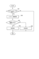
- FIG. 6 is a flowchart of the synchronization process performed by the control unit 211.
- the synchronization process is performed on the premise that the FPD 1 capable of capturing dynamic images is connected to the connector 261 of the communication-enabled slot. It is preferable that the control unit 211 and the FPD 1 are connected by wire, not wirelessly, by connecting the connectors to each other. This is because the control unit 211 and the FPD 1 can be synchronized with high accuracy by reducing communication interruptions and the effects of noise if they are connected by wire. However, under a good wireless communication environment, the control unit 211 may perform synchronization processing with the FPD 1 via wireless communication.
- the control unit 211 may start the synchronization process when the FPD 1 is connected to the connector 261 with which communication is possible.
- the control unit 211 may also start the synchronization process when a command is input by the user U from the operation unit 32.
- the control unit 211 transmits a synchronization instruction to the FPD 1 (S1).
- the FPD 1 receives the synchronization instruction, it returns a response signal to the control unit 211 (S101).
- the control unit 211 receives the response signal, it initializes the count value of the time information (S2), and then transmits the time information and a timing signal to the FPD 1 (S3).
- the FPD 1 generates a copy signal of the received timing signal (S102), and further counts up the count value of the received time information based on the copy signal (S103).
- S104 a notification of completion of synchronization to the control unit 211
- the control unit 211 ends the synchronization process when it receives a notification of completion of synchronization from the FPD 1 .
- the control unit 211 sets an expiration date for the synchronization process.
- the control unit 211 also transmits information about the expiration date to the FPD 1.
- the control unit 211 also registers the expiration date in the storage unit 212 together with the serial number of the FPD 1 that performed the synchronization process.
- the control unit 211 then monitors the arrival of the expiration date for the synchronization process for the FPD 1 whose expiration date has been registered.
- the FPD 1 may display, on a display unit that displays status information, that the synchronization process has been completed and the FPD 1 is in a synchronous state.
- the FPD 1 may also monitor the expiration date. In this case, the FPD 1 may switch the display of the synchronization status on the display unit to an asynchronous state when the expiration date arrives.
- the control unit 211 executes a synchronization state presentation process for presenting information on the synchronization state of the FPD 1, using a predetermined program stored in the storage unit 212.
- the control unit 211 functions as a synchronization state presentation processing unit.
- the information relating to the synchronization state is information that indicates to the user U whether or not the target FPD 1 is in a synchronized state.
- the "information relating to the synchronization state" will be referred to as "synchronization information”.
- the control unit 211 presents the synchronization information by displaying the display unit 31 and the second display unit 29.
- the synchronization information may be displayed either directly or indirectly.
- a direct display is, for example, a display that clearly indicates that synchronization is in progress.
- An indirect display is, for example, a display that does not clearly indicate that synchronization is in progress but allows the user U to understand that synchronization is in progress.
- the synchronization state presentation process is performed according to a number of patterns described below.
- the radiation imaging system 100 may be a system that performs the synchronization state presentation process in only one of a plurality of patterns described below. Also, the radiation imaging system 100 may be a system that performs the synchronization state presentation process in a combination of two or more of a plurality of patterns.
- the synchronization state presentation process (1) executed by the control unit 211 will be described.
- the control unit 211 presents synchronization information.
- the control unit 211 periodically and repeatedly executes the synchronization state presentation process (1).
- FIG. 7 is a flowchart showing the synchronization state presentation process (1) performed by the control unit 211.
- the control unit 211 displays the examination screen 312 shown in Fig. 5 on the display unit 31 (S11). While the examination screen 312 is being displayed, the user U can select an FPD 1 to be used for imaging from among the registered FPDs 1.
- an icon F of the registered FPD 1 is displayed in the image display area 312a of the examination screen 312, an icon F of the registered FPD 1 is displayed. 5 shows an example in which only one icon F is displayed. However, if a plurality of FPDs 1 are registered in the storage unit 212, the icons F of all the FPDs 1 are displayed in the image display area 312a.
- the control unit 211 determines whether or not there is a selection input for the FPD 1 from the user U (S12). If there is no input, the control unit 211 ends the synchronization state presentation process (1). On the other hand, when the control unit 211 detects a selection input of the FPD 1 from the user U, it highlights the icon of the selected FPD 1. The two-dot chain line in Fig. 8 indicates the highlighting. The highlighting is achieved by changing the color or brightness of the icon F, adding a border around the icon F, or the like. Then, the control unit 211 registers in the storage unit 212 that the selected FPD 1 will be used in the radiography order displayed on the examination screen 312 (S13).
- the control unit 211 refers to the information about the selected FPD1 that is recorded in the storage unit 212. The control unit 211 then determines whether the selected FPD1 is in a synchronized state and whether that state continues (S14).
- the control unit 211 causes the display unit 31 to display a positive screen G1 (S15).
- the positive screen G1 is a screen indicating that the FPD 1 is synchronized. 9, the positive screen G1 displays that the dynamic image capturing order is possible. This display corresponds to "presentation of information regarding the synchronization state.”
- the control unit 211 may refer to the storage unit 212 and display information M1 of the time during which synchronization can be maintained based on information on the expiration date of the synchronization state in the positive screen G1.
- the control unit 211 causes the display unit 31 to display a negative screen G2 (S16).
- the negative screen G2 is a screen indicating that the FPD 1 is not synchronized. 10
- the negative screen G2 displays that synchronization is required by the slot connector 261. This display corresponds to "presentation of synchronization information.”
- control unit 211 goes through S15 or S16 and ends the synchronization state presentation process (1).
- the control unit 211 may end the display of the displayed positive screen G1 or negative screen G2 after a certain period of time has elapsed.
- the control unit 211 may display a confirmation button on the displayed positive screen G1 or negative screen G2. In this case, the control unit 211 may end the display of the screen after receiving an input of the confirmation button from the user U.
- the selected FPD 1 may not have the functionality to perform dynamic imaging.
- the control unit 211 may display a screen indicating that the FPD 1 cannot capture dynamic images.
- the synchronization state presentation process (2) executed by the control unit 211 will be described.
- the control unit 211 presents synchronization information when new photographing order information is acquired by addition or the like or when photographing order information is selected by the user through the synchronization state presentation process (2).
- the control unit 211 periodically and repeatedly executes the synchronization state presentation process (2).
- FIG. 11 is a flowchart showing the synchronization state presentation process (2) performed by the control unit 211.
- the control unit 211 determines whether or not examination information or radiography order information for the medical cart RC has been received from the RIS 40, which is an external device (S21). If the examination information or the photographing order information is not received, the control unit 211 advances the process to S22. On the other hand, if the examination information or the photographing order information is received, the control unit 211 advances the process to S23.
- control unit 211 determines whether or not the user U has added or selected radiography order information from the examination screen 312 (FIG. 5), for example. If there is no such input, the control unit 211 ends the synchronization state presentation process (2). If the above input has been received, the control unit 211 advances the process to S23.
- the control unit 211 refers to information recorded in the storage unit 212 regarding the FPD 1 capable of dynamic radiography that is registered in the storage unit 212. Then, the control unit 211 determines whether or not the registered FPD 1 is in a synchronous state and whether or not the synchronous state continues. As a result, if the synchronized state of the FPD 1 continues, the control unit 211 causes the display unit 31 to display a positive screen indicating that the FPD 1 is in a synchronized state (S24). This positive screen may be the same as the positive screen G1 in FIG. 9 described above. On the other hand, if the synchronized state of the FPD 1 is not maintained, the control unit 211 causes the display unit 31 to display a negative screen (S25). This negative screen may be the same as the negative screen G2 of FIG.
- the control unit 211 may perform the determination in S23 for all FPDs 1 capable of capturing dynamic images. Then, the control unit 211 may display a positive screen if there is at least one FPD 1 that continues to be in a synchronized state. Furthermore, the control unit 211 may display a negative screen when there is not even one FPD 1 that continues to be in a synchronized state.
- control unit 211 goes through S24 or S25 and ends the synchronization status presentation process (2).
- the display of the positive screen or the negative screen is ended in the same manner as in the synchronization state presentation process (1).
- the control unit 211 may cause the display unit 31 to display a screen indicating that the FPD 1 cannot perform dynamic imaging.
- the synchronization state presentation process (3) executed by the control unit 211 will be described.
- the control unit 211 presents synchronization information through the synchronization state presentation process (3).
- the control unit 211 periodically and repeatedly executes the synchronization state presentation process (3).
- the change in the synchronous state corresponds to a case where the synchronous state of the FPD 1 is released due to the expiration date.
- the change in the synchronization state may also include a transition from an asynchronous state to a synchronous state.
- the control unit 211 requires a certain amount of time to elapse from the start of execution of the synchronization process to its completion.
- the change in the synchronization state may also include the moment when the synchronization process is completed.
- FIG. 12 is a flowchart showing the synchronization state presentation process (3) performed by the control unit 211.
- the control unit 211 refers to the information of the FPD 1 registered in the storage unit 212. Then, the control unit 211 judges whether or not there is an FPD 1 whose synchronous state is to be released (S31). In this case, the release of the synchronous state refers to the state immediately before the synchronous state is released.
- the term "immediately before” may be, for example, one to several seconds before, or a shorter time.
- the control unit 211 ends the synchronous state presentation process (3). Furthermore, if there is an FPD 1 whose synchronization state is to be released, the control unit 211 causes the display unit 31 to display the negative screen of Fig. 10 (S32). The negative screen may be the negative screen G2 of Fig. 10. Then, the control unit 211 ends the synchronization state presentation process (3).
- the process for ending the display of the negative screen is the same as in the synchronization status presentation process (1).
- the control unit 211 may monitor the FPD 1 during execution of the synchronization process, and when the synchronization process is completed, cause the display unit 31 to display a positive screen.
- the positive screen may be the positive screen G1 in FIG. In this case, the display of the positive screen is terminated in the same manner as in the synchronous state presentation process (1).
- Fig. 13 is an explanatory diagram showing a state in which the FPD 1 is stored in the storage unit 26.
- Fig. 14 is a flowchart showing the synchronization state presentation process (4) performed by the control unit 211.
- the control unit 211 detects the connection of the FPD 1 to a connector in any of the slots in the storage unit 26 (S41).
- the control unit 211 can detect the connection of the FPD 1 to any of the connectors through the power supply circuit 262 connected to each connector.
- control unit 211 If the control unit 211 does not detect the connection of the FPD 1 to any of the connectors, it ends the synchronization state presentation process (4). Furthermore, when the control unit 211 detects that the FPD 1 is connected to any of the connectors, the control unit 211 refers to information about the FPD 1 that is recorded in the storage unit 212 . Then, the control unit 211 determines whether or not the connected FPD 1 is in a synchronized state and whether or not that state continues (S42).
- the control unit 211 causes the display unit 31 to display a positive screen indicating that the FPD 1 is in a synchronized state (S43).
- This positive screen may be the same as the positive screen G1 in FIG. 9 described above.
- the control unit 211 causes the display unit 31 to display a negative screen G3 of Fig. 16 (S44).
- the negative screen G3 indicates that the FPD 1 is in an asynchronous state. Then, the control unit 211 ends the synchronization state presentation process (4).
- the display of the positive screen or the negative screen G3 is terminated in the same manner as in the synchronous state presentation process (1). Furthermore, there may be cases where the FPD 1 stored in the storage unit 26 does not have a function for performing dynamic imaging. In such cases, the control unit 211 may cause the display unit 31 to display a screen indicating that the FPD 1 cannot capture dynamic images.
- the synchronization state presentation process (5) executed by the control unit 211 will be described.
- the control unit 211 performs a synchronization state presentation process (5) to present synchronization information.
- the control unit 211 periodically and repeatedly executes the synchronization state presentation process (5).
- FIG. 15 is an explanatory diagram showing a state in which the FPD 1 is being removed from the storage unit 26.
- the control unit 211 detects the removal of the FPD 1 from the connector in any of the slots in the storage unit 26 (S46).
- the control unit 211 can detect the removal of the FPD 1 from any of the connectors through the power supply circuit 262 connected to each connector.
- control unit 211 If the control unit 211 does not detect the removal of the FPD 1 from any of the connectors, it ends the synchronization state presentation process (5). Furthermore, when removal of the FPD 1 from any of the connectors is detected, the control unit 211 refers to information about the removed FPD 1 that is recorded in the storage unit 212 . Then, the control unit 211 determines whether or not the removed FPD 1 is in a synchronized state and whether or not the synchronized state continues (S47).
- the control unit 211 causes the display unit 31 to display a positive screen indicating that the FPD 1 is in a synchronized state (S48).
- This positive screen may be the same as the positive screen G1 in FIG. 9 described above.
- the control unit 211 causes the display unit 31 to display the negative screen G3 of FIG. 16 (S49). Then, the control unit 211 ends the synchronization state presentation process (5).
- the display of the positive screen or the negative screen G3 is terminated in the same manner as in the synchronous state presentation process (1).
- the control unit 211 may cause the display unit 31 to display a screen indicating that the FPD 1 cannot capture dynamic images.
- the control unit 211 presents information regarding both the synchronous state and the asynchronous state of the FPD 1. From the viewpoint of drawing the attention of the user U, the presentation of the synchronous state is more important than the presentation of the asynchronous state. Therefore, in the synchronous state presentation processes (1), (2), (4), and (5), the control unit 211 may omit the presentation of the synchronous state.
- each screen presenting synchronization information may be supplemented with information identifying the FPD 1.
- information identifying the FPD 1 For example, specific information such as the type, model number, and serial number of the target FPD 1 may also be displayed on each screen.
- the control unit 211 executes a battery remaining capacity display process for displaying information related to the remaining battery capacity of the FPD 1, using a predetermined program stored in the storage unit 212.
- the control unit 211 functions as a battery remaining capacity display processing unit.
- the information relating to the remaining battery level is information that indicates to the user U whether the remaining battery level is appropriate for the target FPD 1 to perform dynamic imaging.
- the "information relating to the remaining battery level" will be referred to as "battery information”.
- the control unit 211 presents the battery information by displaying the display unit 31 and the second display unit 29.
- the battery information may be displayed either directly or indirectly.
- a direct display is, for example, a display that clearly indicates the remaining battery charge itself or whether the remaining battery charge is sufficient.
- An indirect display is, for example, a display that allows the user U to understand whether dynamic shooting is possible or not depending on the remaining battery charge.
- the remaining battery capacity display process is performed according to a number of patterns which will be described below.
- the radiation imaging system 100 may execute the battery remaining capacity display process in only one of a plurality of patterns described below. Also, the radiation imaging system 100 may execute the battery remaining capacity display process in a combination of two or more of a plurality of patterns.
- the battery remaining capacity display process (1) executed by the control unit 211 will be described.
- the control unit 211 presents battery information.
- the control unit 211 periodically and repeatedly executes the battery remaining capacity display process (1).
- FIG. 18 is a flowchart showing the battery remaining capacity display process (1) performed by the control unit 211.
- the control unit 211 displays the examination screen 312 shown in FIG. 5 on the display unit 31 (S51).
- the control unit 211 determines whether or not there is a selection input for the FPD 1 from the user U (S52). If there is no input, the control unit 211 ends the remaining battery level presentation process (1). On the other hand, when the control unit 211 detects a selection input of the FPD 1 from the user U, the control unit 211 performs the following process: The control unit 211 registers in the storage unit 212 that the selected FPD 1 will be used in the radiography order displayed on the examination screen 312 (S53).
- control unit 211 communicates with the selected FPD1 and requests the current remaining battery level (S54). The control unit 211 then obtains the current remaining battery level in response to the response from the FPD1.
- the control unit 211 judges whether the remaining battery level of the selected FPD 1 is equal to or greater than a predetermined value (S55).
- the predetermined value here indicates a remaining battery level at which dynamic radiography can be performed. This value may be set in advance.
- the control unit 211 causes the display unit 31 to display a positive screen (S56).
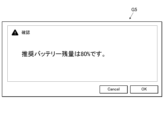
- the positive screen is a screen that clearly indicates that the remaining battery charge is sufficient for dynamic imaging. This screen may be, for example, the same as the positive screen G1 in Fig. 9.
- Fig. 9 shows that the remaining battery power is sufficient to capture a dynamic image, and therefore, capture is possible. This display corresponds to "information regarding the remaining battery power.”
- the control unit 211 may display the remaining battery charge instead of the information M1 of FIG. 9 showing the time during which synchronization can be maintained.
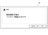
- the control unit 211 causes the display unit 31 to display a negative screen G4 (S57).
- the negative screen G4 is a screen that clearly indicates that the remaining battery level is insufficient for dynamic radiography. 19, the negative screen G4 displays that the FPD 1 needs to be charged by the connector 261 of any of the slots. This display corresponds to "information regarding the remaining battery capacity.”
- control unit 211 goes through S56 or S57 and ends the remaining battery level presentation process (1).
- the control unit 211 may end the display of the displayed positive screen or negative screen G4 after a certain period of time has elapsed.
- the control unit 211 may display a confirmation button on the displayed positive screen or negative screen G4. In this case, the control unit 211 may end the display of the screen after receiving input of the confirmation button.
- the control unit 211 may display the "information regarding the remaining battery power" in stages. For example, it is assumed that a recommended battery remaining capacity and a smaller feasible battery remaining capacity are set.
- the recommended battery remaining capacity is a value that is sufficient to perform dynamic radiography.
- the feasible battery remaining capacity is a value that allows dynamic radiography to be performed.
- the control unit 211 may display a screen showing a recommended remaining battery level when the FPD 1 has a value less than the recommended remaining battery level and equal to or greater than the executable remaining battery level (see FIG. 22). Also, the control unit 211 may display the executable remaining battery level when the FPD 1 has a value less than the executable remaining battery level (see FIG. 23). A display encouraging charging of the battery of the FPD 1 may be added to these screens.
- the control unit 211 may perform the synchronization status presentation process (1) and the battery remaining capacity presentation process (1) in parallel. In that case, the control unit 211 may perform the displays based on each process at different times. The control unit 211 may also divide the display area into two and perform each display.
- control unit 211 may perform individual display for all combinations of the determination results of the respective processes. For example, the control unit 211 may perform the following display. (i) An indication that the FPD 1 is synchronizing and the battery level is sufficient. (ii) FPD1 is synchronizing but the battery level is insufficient. (iii) An indication that the FPD 1 is asynchronous and the battery level is sufficient. (iv) FPD1 is out of sync and the battery is low.
- the battery remaining capacity display process (2) executed by the control unit 211 will be described.
- the control unit 211 presents the battery information when new photographing order information is acquired by addition or the like or when photographing order information is selected by the user through the battery remaining amount presentation process (2).
- the control unit 211 periodically and repeatedly executes the battery remaining capacity display process (2).
- FIG. 20 is a flowchart showing the battery remaining capacity display process (2) performed by the control unit 211.
- the control unit 211 determines whether or not examination information or radiography order information for the medical cart RC has been received from the RIS 40 (S61). If the examination information or the photographing order information is not received, the control unit 211 advances the process to S62. On the other hand, if the examination information or the photographing order information is received, the control unit 211 advances the process to S63.
- control unit 211 determines whether or not the user U has added or selected radiography order information from the examination screen 312 (FIG. 5). If there is no such input, the control unit 211 ends the battery remaining capacity display process (2). If the above input has been received, the control unit 211 advances the process to S63.
- control unit 211 communicates with the FPD1 capable of dynamic imaging registered in the memory unit 212, and requests the current remaining battery level. The control unit 211 then obtains the current remaining battery level in response to the FPD1.
- the control unit 211 determines whether or not the remaining battery level of the selected FPD 1 is equal to or greater than the value that allows dynamic radiography (S64). As a result, if the remaining battery level of the selected FPD 1 is equal to or greater than the level at which dynamic radiography is possible, the control unit 211 causes the display unit 31 to display a positive screen (S65).
- This positive screen may be the positive screen G1 in FIG. 9, as in the above-described battery remaining capacity presentation process (1).
- the control unit 211 causes the display unit 31 to display a negative screen (S66).
- the negative screen may be the same screen as the negative screen G4 in FIG. 19.
- the control unit 211 may perform the determination in S64 for all FPDs 1 capable of capturing dynamic images. If there is even one FPD 1 whose remaining battery charge is equal to or greater than the value that allows dynamic imaging, the control unit 211 may display a positive screen. Also, the control unit 211 may display a negative screen when there is no FPD 1 whose remaining battery charge is equal to or greater than the value that allows dynamic imaging.
- control unit 211 goes through S65 or S66 and ends the remaining battery level presentation process (2).
- the display of the positive screen or the negative screen is ended in the same manner as in the battery remaining capacity display process (1).
- the gradual display of the "information relating to the battery remaining capacity" is the same as in the battery remaining capacity presentation process (1).
- the control unit 211 may perform the synchronization status presentation process (2) and the battery remaining capacity presentation process (2) in parallel. This case is the same as the case where the synchronization status presentation process (1) and the battery remaining capacity presentation process (1) are performed in parallel.
- the remaining battery power display process (3) executed by the control unit 211 will be described.
- the control unit 211 displays battery information through a remaining battery charge display process (3).
- the control unit 211 periodically and repeatedly executes the remaining battery level display process (3).
- FIG. 21 is a flowchart showing the battery remaining capacity display process (3) performed by the control unit 211.
- the control unit 211 communicates with the FPD 1 capable of dynamic radiography registered in the storage unit 212 and requests the current remaining battery level (S71). If there are multiple FPDs 1 capable of dynamic radiography, the control unit 211 requests the current remaining battery levels from all of those FPDs 1. Then, the control unit 211 acquires the current remaining battery level value from the response of the FPD 1 .
- the control unit 211 compares the remaining battery level of the selected FPD 1 with a first threshold value (S72).
- a first threshold value (S72)
- the control unit 211 prepares two threshold levels, a first threshold level and a second threshold level, where the first threshold level is greater than the second threshold level.
- the first threshold value indicates a recommended battery remaining capacity value that is sufficient to perform dynamic radiography
- the second threshold value indicates a viable battery remaining capacity value that allows dynamic radiography to be performed.
- control unit 211 ends the remaining battery level presentation process (3).
- the control unit 211 may display on the display unit 31 that the remaining battery charge of the FPD 1 is equal to or greater than the recommended remaining battery charge.
- the control unit 211 compares the remaining battery charge value with a second threshold (S73). If the remaining battery charge value of the FPD 1 is not less than the second threshold value, the first screen G5 of FIG. 22 is displayed on the display unit 31 (S74).
- the second screen G6 of FIG. 23 is displayed on the display unit 31 (S75).
- the first screen G5 is a screen showing that the remaining battery charge value of the FPD 1 is greater than the executable battery charge but less than the recommended battery charge.
- the second screen G6 is a screen showing that the remaining battery charge value of the FPD 1 is less than the executable battery charge.
- control unit 211 goes through S74 or S75 and ends the remaining battery level display process (3).
- the control unit 211 may set only one threshold value for the remaining battery capacity and make a determination.
- the threshold value is set to only the second threshold value.
- the control unit 211 omits step S72 in the battery remaining amount display process (3).
- the control unit 211 may end the process when it determines NO in step S73.
- the control unit 211 may display on the display unit 31 that the FPD 1 has an executable remaining battery amount or more when it determines NO in step S73.
- control unit 211 may perform the battery level display process (3) for the FPD 1 with the highest remaining battery level.
- the display of the first screen G5 or the second screen G6 is terminated in the same manner as in the display of the screen in the battery remaining capacity display process (1).
- the remaining battery power display process (4) executed by the control unit 211 will be described.
- the control unit 211 displays battery information.
- the control unit 211 periodically and repeatedly executes the remaining battery level display process (4).
- FIG. 24 is a flowchart showing the remaining battery power display process (4) performed by the control unit 211.
- the control unit 211 detects the connection of the FPD 1 to a connector in any of the slots in the storage unit 26 (S81).
- control unit 211 If the control unit 211 does not detect the connection of the FPD 1 to any of the connectors, it ends the remaining battery level presentation process (4). Furthermore, if the control unit 211 detects that the FPD 1 is connected to any of the connectors, the process proceeds to S82.
- control unit 211 communicates with the connected FPD1 and requests the current remaining battery level. The control unit 211 then obtains the current remaining battery level in response to the FPD1.
- the control unit 211 determines whether or not the remaining battery level of the connected FPD 1 is equal to or greater than the value that allows dynamic imaging (S83). As a result, if the remaining battery level of the connected FPD 1 is equal to or greater than the level at which dynamic radiography is possible, the control unit 211 causes the display unit 31 to display a positive screen (S84). Note that this positive screen may be the positive screen G1 in Fig. 9, as in the case of the above-mentioned battery level presentation process (1).
- the control unit 211 causes the display unit 31 to display a negative screen (S85).
- this negative screen may be the negative screen G4 in FIG. 19, as in the case of the battery remaining level presentation process (1) described above.
- control unit 211 goes through S84 or S85 and ends the remaining battery level display process (4).
- the display of the positive screen or the negative screen is ended in the same manner as in the battery remaining capacity display process (1).
- the stepwise display of the "information relating to the battery remaining capacity" is the same as in the battery remaining capacity display process (1).
- control unit 211 may cause the display unit 31 to display a screen indicating that the FPD 1 cannot capture dynamic images.
- the control unit 211 may perform the synchronization status presentation process (4) and the battery remaining capacity presentation process (4) in parallel. This case is the same as the case where the synchronization status presentation process (1) and the battery remaining capacity presentation process (1) are performed in parallel.
- the remaining battery power display process (5) executed by the control unit 211 will be described.
- the control unit 211 displays battery information in a battery remaining capacity display process (5).
- the control unit 211 periodically and repeatedly executes the remaining battery level display process (5).
- FIG. 25 is a flowchart showing the remaining battery power display process (5) performed by the control unit 211.
- the control unit 211 detects removal of the FPD 1 from the connector in any of the slots in the storage unit 26 (S91).
- control unit 211 If the control unit 211 does not detect the removal of the FPD 1 from any of the connectors, it ends the remaining battery level presentation process (5). Moreover, if the control unit 211 detects removal of the FPD 1 from any of the connectors, the process proceeds to S92.
- control unit 211 communicates with the removed FPD 1 and requests the current remaining battery level. The control unit 211 then obtains the current remaining battery level based on the response from the FPD 1.
- the control unit 211 determines whether or not the remaining battery level of the removed FPD 1 is equal to or greater than a level sufficient for dynamic imaging (S93). As a result, if the remaining battery level of the removed FPD 1 is equal to or greater than the level at which dynamic radiography is possible, the control unit 211 causes the display unit 31 to display a positive screen (S94). Note that this positive screen may be the positive screen G1 in Fig. 9, as in the case of the above-mentioned battery level presentation process (1).
- the control unit 211 causes the display unit 31 to display a negative screen (S95).
- this negative screen may be the negative screen G4 in FIG. 19, as in the case of the battery level display process (1) described above.
- control unit 211 goes through S94 or S95 and ends the remaining battery level display process (5).
- the display of the positive screen or the negative screen is ended in the same manner as in the battery remaining capacity display process (1).
- the stepwise display of the "information relating to the battery remaining capacity" is the same as in the battery remaining capacity display process (1).
- control unit 211 may cause the display unit 31 to display a screen indicating that the FPD 1 cannot capture dynamic images.
- the control unit 211 may perform the synchronization status presentation process (5) and the battery remaining capacity presentation process (5) in parallel. This case is the same as the case where the synchronization status presentation process (1) and the battery remaining capacity presentation process (1) are performed in parallel.
- the control unit 211 displays information in two cases.
- the two cases are when the remaining battery capacity of the FPD 1 is sufficient for capturing dynamic images and when it is insufficient. From the viewpoint of alerting the user U, of the above two cases, the case where the remaining battery power is insufficient for capturing dynamic images is of higher importance. Therefore, in the battery remaining power presentation processes (1), (2), (4), and (5), the control unit 211 may omit presenting information when the remaining battery power of the FPD 1 is sufficient for capturing dynamic images.
- each screen that displays battery information may include information that identifies the FPD 1.
- each screen may display specific information such as the type, model number, and serial number of the target FPD 1.
- the control unit 211 executes an equipment information presentation process for presenting information on equipment required for capturing a radiographic image, using a predetermined program stored in the storage unit 212.
- the control unit 211 functions as an equipment information presentation processing unit.
- Equipment required for capturing a radiation image includes an FPD, a grid, an additional filter, etc. Examples of equipment are not limited to these.
- the equipment includes any equipment that may be required depending on the imaging conditions and the imaging mode. In the following description, an example in which the equipment includes an FPD and a grid will be described.
- the equipment-related information is information indicating the equipment required for the target shooting. This information may include information that specifically identifies the equipment, such as the specifications, format, model, and type of the equipment.
- equipment information information regarding equipment
- the equipment information presentation process is performed according to a number of patterns which will be described below.
- the radiation imaging system 100 may perform the equipment information presentation process in only one of a plurality of patterns described below. Also, the radiation imaging system 100 may perform the equipment information presentation process in a combination of two or more of the plurality of patterns.
- the device information presentation process (1) executed by the control unit 211 will be described.
- the control unit 211 presents equipment information.
- the control unit 211 periodically and repeatedly executes the device information presentation process (1).
- FIG. 26 is a flow chart showing the equipment information presentation process (1) performed by the control unit 211.
- the control unit 211 displays the examination screen 312 shown in FIG. 5 on the display unit 31 (S111).
- the control unit 211 determines whether or not there is a selection input for the FPD 1 from the user U (S112). If there is no input, the control unit 211 ends the equipment information presentation process (1). On the other hand, when the control unit 211 detects a selection input of the FPD 1 from the user U, the control unit 211 performs the following process: The control unit 211 registers in the storage unit 212 that the selected FPD 1 will be used in the radiography order displayed on the examination screen 312 (S113).
- the control unit 211 identifies the equipment information based on the radiography order information of the medical cart RC stored in the storage unit 212 (S114).
- the equipment information is the specifications, format, model, type, etc. of the FPD 1 and grid equipment that are necessary or appropriate for the radiography order.
- control unit 211 specifies the FPD 1 from among the FPDs 1 registered in the storage unit 212. However, the control unit 211 may specify an FPD 1 from outside the range of the registered FPDs 1. In addition, when there are multiple pieces of radiography order information for the mobile cart RC stored in the memory unit 212, the control unit 211 may identify the equipment information based on all of the radiography order information.
- the control unit 211 causes the display unit 31 to display a device information presentation screen G7 shown in FIG. 27 on which the identified device information is displayed (S115). Then, the control unit 211 ends the device information presentation process (1).
- the control unit 211 may end the display of the displayed equipment information presentation screen G7 after a certain period of time has elapsed. Alternatively, the control unit 211 may display a confirmation button on the displayed equipment information presentation screen G7. In this case, the control unit 211 may end the display of the screen after receiving input from the confirmation button.
- the control unit 211 may perform the equipment information presentation process (1) and the synchronization status presentation process (1) or the battery remaining capacity presentation process (1) in parallel. In that case, the control unit 211 may perform the display based on each process at different times. The control unit 211 may also divide the display area and perform each display.
- Equipment information presentation process (2) The device information presentation process (2) executed by the control unit 211 will be described.
- the control unit 211 presents equipment information when new photographing order information is acquired by addition or the like or when photographing order information is selected by the user.
- the control unit 211 periodically and repeatedly executes the device information presentation process (2).
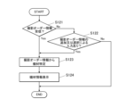
- FIG. 28 is a flowchart showing the device information presentation process (2) performed by the control unit 211.
- the control unit 211 determines whether or not examination information or radiography order information for the medical cart RC has been received from the RIS 40, which is an external device (S121). If the examination information or the photographing order information is not received, the control unit 211 advances the process to S122. On the other hand, if the examination information or the photographing order information is received, the control unit 211 advances the process to S123.
- control unit 211 determines whether or not the user U has added or selected radiography order information from the examination screen 312 (FIG. 5). If there is no input, the control unit 211 ends the equipment information presentation process (2). If the above input has been received, the control unit 211 advances the process to S123.
- the control unit 211 specifies equipment information based on the radiography order information added in S121 or S122.
- the equipment information is the specifications, format, model, type, etc. of the FPD 1 and the grid equipment necessary or appropriate for the radiography indicated by the radiography order information.
- the control unit 211 specifies the FPD 1 from among the FPDs 1 registered in the storage unit 212.
- the control unit 211 may specify an FPD 1 from outside the range of registered FPDs 1.
- the control unit 211 causes the display unit 31 to display a device information presentation screen G7 shown in FIG. 27 on which the identified device information is displayed (S124). Then, the control unit 211 ends the device information presentation process (2).
- the display of the equipment information presentation screen G7 is ended in the same manner as in the equipment information presentation process (1).
- the control unit 211 may perform the equipment information presentation process (2) and the synchronization state presentation process (2) or the battery remaining capacity presentation process (2) in parallel. This case is the same as the case where the equipment information presentation process (1) and the synchronization state presentation process (1) or the battery remaining capacity presentation process (1) are performed in parallel.
- Equipment information presentation process (3) The device information presentation process (3) executed by the control unit 211 will be described.
- the control unit 211 presents equipment information.
- the control unit 211 periodically and repeatedly executes the device information presentation process (3).
- FIG. 29 is a flow chart showing the device information presentation process (3) performed by the control unit 211.
- the control unit 211 displays the examination screen 312 shown in FIG. 5 on the display unit 31 (S131).
- the user U can select an image capture order to be executed by selecting an icon C of an image capture order displayed on the examination screen 312 using the operation unit 32 .
- the control unit 211 determines whether or not a radiography order has been selected and input by the user U (S132). If no input has been made, the control unit 211 ends the equipment information presentation process (3). On the other hand, when the control unit 211 detects a selection input of a radiography order from the user U, the control unit 211 performs the following process: The control unit 211 registers in the storage unit 212 that the selected radiography order is a subject of radiography (S133).
- the control unit 211 identifies the equipment information based on the radiography order selected by the user U (S134).
- the equipment information is the specifications, format, model, type, etc. of the FPD 1 and grid equipment necessary or appropriate for the radiography indicated by the radiography order information.
- the control unit 211 preferably identifies the FPD1 from among the FPD1s registered in the storage unit 212. However, the control unit 211 may identify an FPD1 from outside the range of registered FPD1s.
- the control unit 211 causes the display unit 31 to display a device information presentation screen G7 shown in FIG. 27 on which the identified device information is displayed (S135). Then, the control unit 211 ends the device information presentation process (3).
- the display of the equipment information presentation screen G7 is terminated in the same manner as in the equipment information presentation process (1).
- Equipment information presentation process (4) The device information presentation process (4) executed by the control unit 211 will be described.
- the control unit 211 presents equipment information.
- the control unit 211 periodically and repeatedly executes the device information presentation process (4).
- Preparatory operations for imaging include moving the medical cart RC, adjusting the position and orientation of the tube 23 on the tube support portion 24, and the like.
- the movement of the medical cart RC can be detected by an acceleration sensor provided somewhere on the medical cart RC, a rotation sensor provided on the wheels 27, etc.
- the adjustment of the position and orientation of the tube 23 can be detected by an acceleration sensor provided near the tube 23 on the tube support part 24.
- the adjustment of the orientation can be detected by an acceleration sensor and a rotation sensor provided in the joint mechanism of the tube support part 24.
- the control unit 211 illustrates an example of the equipment information presentation process (4) in which equipment information is presented by moving the medical cart RC.
- FIG. 30 is a flow chart showing the device information presentation process (4) performed by the control unit 211.
- the control unit 211 determines whether or not movement of the medical cart RC has occurred (S141). If the movement of the medical cart RC is not detected, the control unit 211 ends the equipment information presentation process (4).
- the control unit 211 identifies the equipment information based on the radiography order information of the medical examination cart RC stored in the storage unit 212 (S142).
- the equipment information is the specifications, format, model, type, etc. of the FPD1 and grid equipment necessary or appropriate for the radiography indicated by the radiography order information.
- control unit 211 specifies the FPD 1 from among the FPDs 1 registered in the storage unit 212. However, the control unit 211 may specify an FPD 1 from outside the range of the registered FPDs 1. In addition, when there are multiple pieces of radiography order information for the mobile cart RC stored in the memory unit 212, the control unit 211 may identify the equipment information based on all of the radiography order information.
- the control unit 211 causes the display unit 31 to display a device information presentation screen G7 shown in FIG. 27 on which the identified device information is displayed (S143). Then, the control unit 211 ends the device information presentation process (4).
- the display of the equipment information presentation screen G7 is terminated in the same manner as in the equipment information presentation process (1).
- the control unit 211 can select whether to execute or not execute the various processes described above depending on the settings.
- the various processes refer to synchronization status presentation processes (1) to (5), remaining battery capacity presentation processes (1) to (5), and device information presentation processes (1) to (4).
- the above settings can be made by the user U through the operation unit 32.
- the operation unit 32 functions as a setting input unit.
- the control unit 211 causes the display unit 31 to present synchronization information of the FPD 1 . If the synchronization information is presented when the FPD 1 is stored in the storage unit 26, the user U will pay attention to the synchronization information. This enables the system 100 to allow the user U to accurately recognize the synchronization information. Furthermore, the system 100 can reduce the chance of the user U making a mistake in capturing dynamic images using an unsynchronized FPD 1 .
- the control unit 211 causes the display unit 31 to display the synchronization information of the FPD 1 . If the synchronization information is presented when the FPD 1 is removed from the storage unit 26, the user U will pay attention to the synchronization information. This enables the system 100 to allow the user U to accurately recognize the synchronization information. Furthermore, the system 100 can reduce the chance of the user U making a mistake in capturing dynamic images using an unsynchronized FPD 1 .
- the control unit 211 causes the display unit 31 to present synchronization information of the FPD 1. If the synchronization information is presented when the FPD 1 is selected, the user U will pay attention to the synchronization information. Furthermore, when the FPD 1 is selected, the user U often focuses his or her attention on the display unit 31. This enables the system 100 to allow the user U to accurately recognize the synchronization information. Furthermore, the system 100 can reduce the chance of the user U making a mistake in capturing dynamic images using an unsynchronized FPD 1 .
- the control unit 211 when radiography order information is acquired from an external device, or when radiography order information is added, the control unit 211 causes the display unit 31 to present synchronization information of the FPD 1.
- the control unit 211 when the imaging order information is acquired, for example, when the user selects the imaging order information, the control unit 211 causes the display unit 31 to present the synchronization information of the FPD 1. If the synchronization information is presented when the photographing order information is acquired, the user U will pay attention to the synchronization information. Furthermore, when the photographing order information is acquired, the user U often focuses his or her attention on the display unit 31. This enables the system 100 to allow the user U to accurately recognize the synchronization information. Furthermore, the system 100 can reduce the chance of the user U making a mistake in capturing dynamic images using an unsynchronized FPD 1 .
- the control unit 211 causes the display unit 31 to present the synchronization information of the FPD 1.
- a change in the synchronization state of the FPD 1 is an important matter for the user U who is taking dynamic images. In this way, the system 100 can allow the user U to promptly and accurately recognize this important matter from the time it occurs. Furthermore, it is difficult for the user U to recognize a change in the synchronization state that is not apparent from the appearance of the FPD 1. However, the system 100 makes it possible for the user U to accurately recognize a change in the synchronization state. Furthermore, the system 100 can reduce the chance of the user U making a mistake in capturing dynamic images using an unsynchronized FPD 1 .
- the control unit 211 causes the display unit 31 to present information M1 on the time during which the FPD 1 can maintain the synchronous state. Therefore, the system 100 can allow the user U to accurately recognize the time during which the FPD 1 can maintain the synchronized state. Furthermore, the system 100 can reduce the chance of the user U making a mistake in capturing dynamic images with an FPD 1 whose synchronization time has expired.
- the control unit 211 causes the display unit 31 to display battery information of the FPD 1 at a determined timing. Therefore, the system 100 can draw the user U's attention to the battery information, as compared to a case in which the battery information is constantly presented.
- the control unit 211 causes the display unit 31 to display battery information of the FPD 1. If the battery information is presented when the FPD 1 is stored in the storage unit 26, the user U will pay attention to the battery information. This enables the system 100 to allow the user U to accurately recognize the battery information. Furthermore, the system 100 can reduce the chance of the user U making a mistake in capturing dynamic images using the FPD 1 that has a low battery.
- the control unit 211 causes the display unit 31 to display battery information of the FPD 1. If the battery information is presented when the FPD 1 is removed from the storage unit 26, the user U will pay attention to the battery information. This enables the system 100 to allow the user U to accurately recognize the battery information. Furthermore, the system 100 can reduce the chance of the user U making a mistake in capturing dynamic images using an FPD 1 that has a low battery.
- the control unit 211 causes the display unit 31 to display battery information of the FPD 1. If the battery information is presented when the FPD 1 is selected, the user U will pay attention to the battery information. Furthermore, when the FPD 1 is selected, the user U often focuses his or her attention on the display unit 31. This enables the system 100 to allow the user U to accurately recognize the battery information. Furthermore, the system 100 can reduce the chance of the user U making a mistake in capturing dynamic images using an FPD 1 that has a low battery.
- the control unit 211 when radiography order information is acquired from an external device or when radiography order information is added, the control unit 211 causes the display unit 31 to present battery information of the FPD 1.
- radiography order information is acquired, such as when radiography order information is selected by a user
- the control unit 211 causes the display unit 31 to present battery information of the FPD 1. If the battery information is presented when the photographing order information is acquired, the user U will pay attention to the battery information. Furthermore, when the photographing order information is acquired, the user U often focuses his or her attention on the display unit 31. This enables the system 100 to allow the user U to accurately recognize the battery information. Furthermore, the system 100 can reduce the chance of the user U making a mistake in capturing dynamic images using an FPD 1 that has a low battery.
- the control unit 211 causes the display unit 31 to present battery information of the FPD 1.
- a decrease in the remaining battery power of the FPD 1 is an important matter for the user U who is taking dynamic images. In this way, the system 100 can promptly and accurately make the user U aware of this important matter from the time it occurs. In addition, it is difficult for the user U to recognize a decrease in the remaining battery power, which is not visible from the outside of the FPD 1. However, the system 100 makes it possible for the user U to accurately recognize the change in the remaining battery power. Furthermore, the system 100 can reduce the chance of the user U making a mistake in capturing dynamic images using an FPD 1 that has a low battery.
- the control unit 211 causes the display unit 31 to present equipment information relating to equipment required for shooting at a predetermined timing. Therefore, the system 100 can draw the user U's attention to the equipment information, as compared to a case in which the equipment information is constantly presented.
- the control unit 211 causes the display unit 31 to present equipment information. If the equipment information is presented when the FPD 1 is selected, the user U will pay attention to the equipment information. Furthermore, when the FPD 1 is selected, the user U often focuses his or her attention on the display unit 31. This enables the system 100 to allow the user U to accurately recognize the equipment information. Furthermore, the FPD 1 that will perform imaging is often selected at the preparation stage before imaging using the FPD 1 is performed. This allows the system 100 to enable the user U to properly prepare the equipment and smoothly prepare for photography. Furthermore, the system 100 can reduce mistakes made by the user U, such as a lack of equipment or an incorrect selection of equipment, that prevent imaging using the FPD 1 from being performed.
- the control unit 211 causes the display unit 31 to present equipment information. If the equipment information is presented when the photographing order information is acquired, the user U will pay attention to the equipment information. Furthermore, when the photographing order information is acquired, the user U often focuses his or her attention on the display unit 31. This enables the system 100 to allow the user U to accurately recognize the equipment information. Furthermore, when an imaging order is received, the user U often starts preparations for imaging using the FPD 1 . This allows the system 100 to allow the user U to properly prepare the equipment and smoothly prepare for photography. Furthermore, the system 100 can reduce mistakes made by the user U, such as a lack of equipment or an incorrect selection of equipment, that prevent imaging using the FPD 1 from being performed.
- the control unit 211 causes the display unit 31 to display equipment information. If the equipment information is presented when an image capture order is selected, the user U will pay attention to the equipment information. Furthermore, when selecting an image capture order, the user U often focuses his or her attention on the display unit 31. This enables the system 100 to allow the user U to accurately recognize the equipment information. Furthermore, when an imaging order is selected, the user U often starts preparations for imaging using the FPD 1 . This allows the system 100 to allow the user U to properly prepare the equipment and smoothly prepare for photography. Furthermore, the system 100 can reduce mistakes made by the user U, such as a lack of equipment or an incorrect selection of equipment, that prevent imaging using the FPD 1 from being performed.
- the control unit 211 causes the display unit 31 to present equipment information. If the equipment information is presented when a preparation operation for shooting is detected, the user U will pay attention to the equipment information. This allows the system 100 to allow the user U to accurately recognize the equipment information. Furthermore, the system 100 can provide equipment information to the user U who is preparing to shoot at the right time. Therefore, the user U can properly prepare the equipment and smoothly prepare for photography. Furthermore, the system 100 can reduce mistakes made by the user U, such as a lack of equipment or an incorrect selection of equipment, that prevent imaging using the FPD 1 from being performed.
- the radiation imaging system 100 has a mobile radiology cart RC as a mobile radiation irradiation device. This makes it possible to move to various locations within the medical facility and perform radiation image capture. Furthermore, the control unit 211 can perform a synchronization state presentation process, a battery remaining amount presentation process, or an equipment information presentation process. Therefore, in radiographic image capture that involves movement due to rounds, the system 100 can provide accurate imaging support.
- the display units 31 and 29 are disposed on the console 3, the frame of the tube 23, and the device body 21. This allows the user U to receive various pieces of information at a position appropriate for the work being performed.
- the system 100 presents various information by sound, light, or vibration, allowing the user U to perform shooting without gazing at the display unit. Therefore, the system 100 can improve the operability of the user U.
- the radiation imaging system 100 has an operation unit 32 into which a setting for whether to execute or not execute presentation on the display unit 31 is input. Therefore, it is possible to receive the presentation of information suitable for the environment in which the radiation imaging system 100 is used. In addition, since the presentation of unnecessary information can be avoided, it is possible to more accurately provide necessary information to the user U. Furthermore, in the imaging order display area (reference numeral 312c in FIG. 4), when there is no imaging order for dynamic imaging or when imaging has already been performed even if there is an imaging order for dynamic imaging, the presentation of unnecessary information can be avoided by not presenting the synchronization state.
- the subject S When capturing a radiation image, the subject S is positioned in advance. During positioning, an offset calibration image is captured using the FPD 1.
- the offset calibration image is an image obtained by capturing an image using the FPD 1 without irradiating radiation. A plurality of offset calibration images are acquired and averaged. The offset calibration image obtained by this averaging is used for correction processing such as noise removal of the radiation image irradiated with radiation.
- the control unit 211 may use the offset calibration image described above to determine whether or not the radiographic image obtained by imaging is appropriate. Specifically, the control unit 211 determines the change in posture after positioning from the fluctuation of the signal of the offset calibration image.
- the control unit 211 displays the appropriateness of the radiographic image on the display unit 31. If the change in posture is greater than the specified range, the control unit 211 displays the defective capture of the radiographic image on the display unit 31. This allows the user U to determine whether radiation can be irradiated before the radiation irradiation. Also, even after the start of irradiation, the user U can immediately determine whether the image is appropriate. Therefore, it becomes possible to decide on the spot whether to retake the image. Alternatively, if it is determined that the offset calibration image is not appropriate after the start of irradiation, the offset calibration image can be acquired again after the radiation irradiation is completed.
- the FPD 1 may be equipped with detection elements such as strain gauges and pressure sensors.
- the control unit 211 receives the detection results of the detection elements on the spot through the FPD 1.
- the detection results of the detection elements indicate the fluctuations in the pressure that the FPD 1 receives from the subject S. Therefore, the control unit 211 can determine the change in posture after positioning from the detection results of the detection elements. In this case as well, the control unit 211 can determine the change in posture when capturing a radiographic image and decide whether the radiographic image is appropriate.
- the image data of the radiographic image captured by the FPD 1 may be transmitted to a portable terminal such as a registered tablet in advance.
- the image data obtained from the FPD 1 may be transmitted by the console 3 to the portable terminal. This enables medical personnel such as doctors to easily and quickly check images.
- the control unit 211 causes the display unit 31 and the second display unit 29 to display a pre-imaging screen indicating that imaging will be performed immediately before imaging is performed.
- the control unit 211 may display this pre-shooting screen on the display unit 31 and the second display unit 29 so that it is visually different between still image shooting and dynamic image shooting.
- the visual difference is preferably a visually clear one, such as a difference in color or brightness, a difference in screen configuration, or only one of the screens flashing. This allows the user U to clearly recognize whether still image shooting or dynamic image shooting is being performed.
- the control unit 211 may also cause the second display unit 29 to display the display status of radiation.
- the display status of radiation is a status of whether or not radiation is being irradiated. This allows the user U to check the display status of radiation during imaging while looking at the second display unit 29 on the tube 23 side without looking at the console 3.
- control unit 211 may cause the audio output unit 33 to output a sound that is repeated at regular intervals during irradiation of radiation for imaging.
- the user U can grasp the irradiation time by ear by counting the sounds output during irradiation of radiation. Therefore, the user U can irradiate radiation for an appropriate time while gazing at an area to be monitored or observed during capture of a radiation image.
- a display unit may be provided in a location other than the display unit 31 and the second display unit 29.
- This display unit displays the same content as the display unit 31 or the second display unit 29.
- This display unit may be provided in the radiation imaging system 100 together with the display unit 31 and the second display unit 29 or in place of the display unit 31 and the second display unit 29.
- This display unit may be provided at a location other than the display unit 31 and the second display unit 29 of the device body 21 of the medical cart RC.
- the control unit 211 may present various pieces of information in a form different from that displayed by the display unit 31 or the second display unit 29 .
- the various processes mentioned above refer to synchronization status presentation processes (1) to (5), remaining battery capacity presentation processes (1) to (5), and device information presentation processes (1) to (4).
- the other modes include sound, light, vibration, etc.
- the audio output unit 33 is utilized.
- a lamp is newly provided in the radiation imaging system 100.
- vibration a vibrator is newly provided in the radiation imaging system 100.
- the control unit 211 can display various types of information by changing the continuous repeated output, the number of repeated outputs, the period of the repeated output, etc.
- the control unit 211 may use a combination of multiple types of sound, multiple colors of light, etc.
- the radiation generation device 2 and the console 3 share the control unit 211 , the storage unit 212 , and the communication unit 214 .
- the present invention is not limited to this, and the radiation generating device 2 and the console 3 may each have a control unit, a storage unit, and a communication unit separately.
- only one of the control unit of the radiation generating device 2 and the control unit of the console 3 may execute the various processes described above.
- the various processes mentioned above refer to synchronization status presentation processes (1) to (5), remaining battery capacity presentation processes (1) to (5), and device information presentation processes (1) to (4).
- the control unit of the radiation generating device 2 and the control unit of the console 3 may separately share and perform smaller units of processing included in the various types of processing described above.
- the above-described radiation imaging system 100 includes a medical cart RC, but is not limited to this.
- both the radiation generating device 2 and the console 3 may be stored in a stationary housing or a portable housing other than a medical cart.
- the radiation generating device 2 and the console 3 may be configured as separate entities rather than being integrated.
- the present invention has industrial applicability for a radiography system, a radiography system imaging support method, and a program.
- FPD radio imaging device
- Radiation generating device Radiation irradiation device
- Console 21 Device body 211 Control unit 212 Memory unit 213 Generator 214 Communication unit 22 Irradiation instruction switch 23 Tube 24 Tube support unit 25 Collimator 26 Storage unit 27 Wheels 28
- Optical photographing unit 31 Display unit 32 Operation unit (setting input unit) 33 Audio output unit 100 Radiography system 261 Connector 262 Power supply circuit 311 Display screen 311a List 312 Examination screen B Bed C Icon F Icon G1 Positive screen G2 Negative screen G3 Negative screen G4 Negative screen G7 Equipment information presentation screen G7 Equipment information presentation screen ID Patient M1 Information N Communication network R Radiation RC Mobile radiation irradiation device S Subject (subject) U User
Landscapes
- Health & Medical Sciences (AREA)
- Life Sciences & Earth Sciences (AREA)
- Medical Informatics (AREA)
- Engineering & Computer Science (AREA)
- Radiology & Medical Imaging (AREA)
- Biomedical Technology (AREA)
- Biophysics (AREA)
- Nuclear Medicine, Radiotherapy & Molecular Imaging (AREA)
- Optics & Photonics (AREA)
- Pathology (AREA)
- Physics & Mathematics (AREA)
- High Energy & Nuclear Physics (AREA)
- Heart & Thoracic Surgery (AREA)
- Molecular Biology (AREA)
- Surgery (AREA)
- Animal Behavior & Ethology (AREA)
- General Health & Medical Sciences (AREA)
- Public Health (AREA)
- Veterinary Medicine (AREA)
- Apparatus For Radiation Diagnosis (AREA)
Abstract
撮影装置の信号の同期の有無を適正に提示するために、放射線撮影システム100は、放射線照射装置2と同期する放射線画像撮影装置1と、放射線画像撮影装置の同期情報を提示する提示部31とその制御部211とを備える。制御部は、放射線画像撮影装置が格納部26に格納された時又は放射線画像撮影装置が格納部から取り出された時に同期情報を提示部に提示する。或いは、制御部は、放射線画像撮影装置が選択された時、制御部において、撮影オーダー情報が取得、追加、選択された時に同期情報を提示部に提示する。
Description
本発明は、放射線撮影システム、放射線撮影システムの撮影支援方法及びプログラムに関する。
従来より、放射線を発生させる放射線照射装置と、放射線を受けて放射線画像データを生成する放射線撮影装置とを備えた放射線撮影システムが利用されている。
放射線画像撮影には、被検体を一定間隔で連続して撮影を行って複数のフレーム画像を得る動画撮影の手法がある。
動画撮影においては、放射線曝射のタイミングと放射線画像の生成のタイミングとの同期を図る必要がある「動態」撮影と、撮影開始、終了のタイミングのみ同期する必要がある「透視」撮影の二種類がある。
このため、特許文献1及び2の放射線撮影システムでは、放射線照射装置の照射に放射線撮影装置の画像生成のタイミングを合わせる同期処理を行っていた。
放射線画像撮影には、被検体を一定間隔で連続して撮影を行って複数のフレーム画像を得る動画撮影の手法がある。
動画撮影においては、放射線曝射のタイミングと放射線画像の生成のタイミングとの同期を図る必要がある「動態」撮影と、撮影開始、終了のタイミングのみ同期する必要がある「透視」撮影の二種類がある。
このため、特許文献1及び2の放射線撮影システムでは、放射線照射装置の照射に放射線撮影装置の画像生成のタイミングを合わせる同期処理を行っていた。
特許文献1のシステムの場合、コンソールは同期状態を認識しているが、撮影技術者に対する同期状態の明示が言及されていない。
特許文献2のシステムの場合、表示装置に撮影装置が信号の同期の有無を表示部に表示させている。しかしながら、撮影時のワークフローにおいてユーザーが表示部を見ていないと思われるタイミングで表示画面に表示するのみなどの問題がある。このため、撮影技術者に対する注意を喚起するには改善の余地があった。
特許文献2のシステムの場合、表示装置に撮影装置が信号の同期の有無を表示部に表示させている。しかしながら、撮影時のワークフローにおいてユーザーが表示部を見ていないと思われるタイミングで表示画面に表示するのみなどの問題がある。このため、撮影技術者に対する注意を喚起するには改善の余地があった。
本発明は、放射線画像撮影装置の同期の有無を適切なタイミング、方法でユーザーへ伝えることで、より効果的に注意を喚起することを課題とする。
上記課題を解決するために、本発明の放射線撮影システムは、
放射線照射装置と同期して動画撮影を行う放射線画像撮影装置と、
前記放射線照射装置に対する前記放射線画像撮影装置の同期状態に関する情報を提示する提示部と、
前記提示部を制御する制御部と、
を備え、
前記制御部は、前記放射線画像撮影装置が格納部に格納された時、前記放射線画像撮影装置が前記格納部から取り出された時、撮影を行う前記放射線画像撮影装置が選択された時、前記制御部が外部装置から撮影オーダー情報を取得した時、撮影オーダー情報が追加された時、又は、ユーザーにより撮影オーダー情報が選択された時の少なくともいずれか一つのタイミングで前記放射線画像撮影装置の同期状態を判定し、前記放射線画像撮影装置の同期状態に関する情報を前記提示部に提示させる。
放射線照射装置と同期して動画撮影を行う放射線画像撮影装置と、
前記放射線照射装置に対する前記放射線画像撮影装置の同期状態に関する情報を提示する提示部と、
前記提示部を制御する制御部と、
を備え、
前記制御部は、前記放射線画像撮影装置が格納部に格納された時、前記放射線画像撮影装置が前記格納部から取り出された時、撮影を行う前記放射線画像撮影装置が選択された時、前記制御部が外部装置から撮影オーダー情報を取得した時、撮影オーダー情報が追加された時、又は、ユーザーにより撮影オーダー情報が選択された時の少なくともいずれか一つのタイミングで前記放射線画像撮影装置の同期状態を判定し、前記放射線画像撮影装置の同期状態に関する情報を前記提示部に提示させる。
また、本発明の放射線撮影システムの撮影支援方法は、
放射線照射装置と同期して動画撮影を行う放射線画像撮影装置と前記放射線照射装置に対する前記放射線画像撮影装置の同期状態に関する情報を提示する提示部と前記提示部を制御する制御部とを有する放射線撮影システムの撮影支援方法であって、
前記放射線画像撮影装置が格納部に格納された時、前記放射線画像撮影装置が前記格納部から取り出された時、撮影を行う前記放射線画像撮影装置が選択された時、前記制御部が外部装置から撮影オーダー情報を取得した時、撮影オーダー情報が追加された時、又は、ユーザーにより撮影オーダー情報が選択された時の少なくともいずれか一つのタイミングで前記放射線画像撮影装置の同期状態を判定し、前記放射線画像撮影装置の同期状態に関する情報を前記提示部に提示させる。
放射線照射装置と同期して動画撮影を行う放射線画像撮影装置と前記放射線照射装置に対する前記放射線画像撮影装置の同期状態に関する情報を提示する提示部と前記提示部を制御する制御部とを有する放射線撮影システムの撮影支援方法であって、
前記放射線画像撮影装置が格納部に格納された時、前記放射線画像撮影装置が前記格納部から取り出された時、撮影を行う前記放射線画像撮影装置が選択された時、前記制御部が外部装置から撮影オーダー情報を取得した時、撮影オーダー情報が追加された時、又は、ユーザーにより撮影オーダー情報が選択された時の少なくともいずれか一つのタイミングで前記放射線画像撮影装置の同期状態を判定し、前記放射線画像撮影装置の同期状態に関する情報を前記提示部に提示させる。
本発明のプログラムは、
放射線照射装置と同期して動画撮影を行う放射線画像撮影装置と前記放射線照射装置に対する前記放射線画像撮影装置の同期状態に関する情報を提示する提示部と前記提示部を制御する制御部とを有する放射線撮影システムのコンピュータに、
前記放射線画像撮影装置が格納部に格納された時、前記放射線画像撮影装置が前記格納部から取り出された時、撮影を行う前記放射線画像撮影装置が選択された時、前記制御部が外部装置から撮影オーダー情報を取得した時、撮影オーダー情報が追加された時、又は、ユーザーにより撮影オーダー情報が選択された時の少なくともいずれか一つのタイミングで前記放射線画像撮影装置の同期状態を判定し、前記放射線画像撮影装置の同期状態に関する情報を前記提示部に提示させる機能を実現させる。
放射線照射装置と同期して動画撮影を行う放射線画像撮影装置と前記放射線照射装置に対する前記放射線画像撮影装置の同期状態に関する情報を提示する提示部と前記提示部を制御する制御部とを有する放射線撮影システムのコンピュータに、
前記放射線画像撮影装置が格納部に格納された時、前記放射線画像撮影装置が前記格納部から取り出された時、撮影を行う前記放射線画像撮影装置が選択された時、前記制御部が外部装置から撮影オーダー情報を取得した時、撮影オーダー情報が追加された時、又は、ユーザーにより撮影オーダー情報が選択された時の少なくともいずれか一つのタイミングで前記放射線画像撮影装置の同期状態を判定し、前記放射線画像撮影装置の同期状態に関する情報を前記提示部に提示させる機能を実現させる。
本発明によれば、放射線画像撮影装置の同期の有無を適切にユーザーへ伝え、より効果的に注意を喚起することができる。
添付図面を参照して、本発明に係る実施の形態を詳細に説明する。なお、本発明は、図示例に限定されるものではない。
[放射線撮影システムの概略構成]
図1、図2を参照して、本実施形態の装置構成を説明する。図1は放射線撮影システム100を示す概略構成図である。図2は回診車RCの構成を示すブロック図である。
図1、図2を参照して、本実施形態の装置構成を説明する。図1は放射線撮影システム100を示す概略構成図である。図2は回診車RCの構成を示すブロック図である。
放射線撮影システム100は、病院などの医療施設に設けられる。
医療施設の撮影技師などのユーザーUは、回診対象の患者の回診を行う。その際、ユーザーUは、放射線撮影システム100とともに、当該患者がいる病棟、手術室等の回診先に移動して、患者を放射線撮影する。ここでは、回診先が病棟であり、病棟にベッドBが設置されている場合を例示する。被写体としての患者の被検者Sは、例えば、ベッドBの上で臥位の姿勢をとっている状態で放射線撮影が行われる。
医療施設の撮影技師などのユーザーUは、回診対象の患者の回診を行う。その際、ユーザーUは、放射線撮影システム100とともに、当該患者がいる病棟、手術室等の回診先に移動して、患者を放射線撮影する。ここでは、回診先が病棟であり、病棟にベッドBが設置されている場合を例示する。被写体としての患者の被検者Sは、例えば、ベッドBの上で臥位の姿勢をとっている状態で放射線撮影が行われる。
放射線撮影システム100は、放射線画像撮影装置であるFPD1と、移動型放射線照射装置である回診車RCと、を備える。FPDは、Flat Panel Detectorの略称である。
FPD1と回診車RCとは、例えば、無線通信を介して互いに通信可能である。
FPD1と回診車RCとは、例えば、無線通信を介して互いに通信可能である。
放射線撮影システム100は、一又は複数のFPD1を有する。放射線撮影システム100は、静止画撮影と動画撮影の両方が可能なFPD1を少なくとも一台以上有する。さらに、放射線撮影システム100は、静止画撮影のみが可能なFPD1も有してもよい。
静止画撮影とは、1回の撮影操作に応じて一枚の被写体Sの画像を取得することをいう。
静止画撮影においてもFPDと放射線照射装置は同期しているが、同期は照射の直前(少なくとも照射ボタン押下後)に行われる。これに対して、後述する動態撮影の同期は、照射ボタンが押下される前から実施される点が静止画撮影の同期とは異なる。
また、静止画撮影の同期は、照射開始要求→FPDの撮影準備~完了→照射許可→照射→読出しの動作が照射ごとに行われる、一連の逐次的な要求と応答による動作である。これに対して、動態撮影の同期は放射線の照射ごとに放射線照射装置とFPDとの間で逐次的なやり取りは行われない、非逐次的な動作である。この点においても静止画撮影と動態撮影の同期は異なる。本願明細書及び特許請求の範囲において「同期」という場合には、特にことわりがない場合には、「静止画撮影の同期」は含まれず、動画撮影の同期を示すものとする。
動画撮影とは、一回の撮影操作に応じて、被写体Sに対し、連続する複数回の撮影を行って被写体Sの複数の画像を取得することをいう。動画撮影のうち、X線等の放射線をパルス状にして所定時間間隔で繰り返し照射するパルス照射に同期的に撮影を行う方法を、動態撮影と呼ぶ。
また、以下の説明では、動態撮影を動態画像の撮影という場合がある。
静止画撮影とは、1回の撮影操作に応じて一枚の被写体Sの画像を取得することをいう。
静止画撮影においてもFPDと放射線照射装置は同期しているが、同期は照射の直前(少なくとも照射ボタン押下後)に行われる。これに対して、後述する動態撮影の同期は、照射ボタンが押下される前から実施される点が静止画撮影の同期とは異なる。
また、静止画撮影の同期は、照射開始要求→FPDの撮影準備~完了→照射許可→照射→読出しの動作が照射ごとに行われる、一連の逐次的な要求と応答による動作である。これに対して、動態撮影の同期は放射線の照射ごとに放射線照射装置とFPDとの間で逐次的なやり取りは行われない、非逐次的な動作である。この点においても静止画撮影と動態撮影の同期は異なる。本願明細書及び特許請求の範囲において「同期」という場合には、特にことわりがない場合には、「静止画撮影の同期」は含まれず、動画撮影の同期を示すものとする。
動画撮影とは、一回の撮影操作に応じて、被写体Sに対し、連続する複数回の撮影を行って被写体Sの複数の画像を取得することをいう。動画撮影のうち、X線等の放射線をパルス状にして所定時間間隔で繰り返し照射するパルス照射に同期的に撮影を行う方法を、動態撮影と呼ぶ。
また、以下の説明では、動態撮影を動態画像の撮影という場合がある。
[FPD]
FPD1は、放射線発生装置2から放射された放射線Rに応じた放射線画像データを生成する装置である。
FPD1は、パネル状に構成されている。FPD1は、可搬型である。
ユーザーUは、FPD1を撮影台に装填して用いることが可能である。ユーザーUは、被検者SとベッドBとの間にFPD1を水平に配置して用いることが可能である。その際、被検者Sは、ベッドの上で臥位の姿勢をとっている。また、ユーザーUは、図1のように、被検者Sとベッドとの間にFPD1を配置して用いることが可能である。
FPD1は、放射線発生装置2から放射された放射線Rに応じた放射線画像データを生成する装置である。
FPD1は、パネル状に構成されている。FPD1は、可搬型である。
ユーザーUは、FPD1を撮影台に装填して用いることが可能である。ユーザーUは、被検者SとベッドBとの間にFPD1を水平に配置して用いることが可能である。その際、被検者Sは、ベッドの上で臥位の姿勢をとっている。また、ユーザーUは、図1のように、被検者Sとベッドとの間にFPD1を配置して用いることが可能である。
FPD1は、例えば、シンチレーター、PD、TFTスイッチ等を有する。PDは、Photo Diodeの略称である。TFTは、Thin Film Transistorの略称である。シンチレーター、PD、TFTスイッチ等の図示は省略する。シンチレーターは、入射した放射線Rを光に変換する。PDは、画素に対応してマトリックス状に配置される。TFTスイッチは、各PDに対応して配置される。
入射した放射線Rは、シンチレーターで光に変換され、PDに入射する。放射線Rが入射したPDは、画素ごとに電荷として蓄積する。PDに蓄積された電荷は、TFTスイッチから信号線に流れ出す。電荷は、増幅されて放射線画像データにA/D変換される。放射線画像データは、回診車RCに出力される。
上記FPD1は、間接変換型である。但し、FPD1は、放射線Rを直接電気信号に変換する直接変換型で構成されてもよい。
入射した放射線Rは、シンチレーターで光に変換され、PDに入射する。放射線Rが入射したPDは、画素ごとに電荷として蓄積する。PDに蓄積された電荷は、TFTスイッチから信号線に流れ出す。電荷は、増幅されて放射線画像データにA/D変換される。放射線画像データは、回診車RCに出力される。
上記FPD1は、間接変換型である。但し、FPD1は、放射線Rを直接電気信号に変換する直接変換型で構成されてもよい。
[回診車]
回診車RCは、図2のように、通信ネットワークNを介して、RIS40との通信が可能である。RISは、Radiology Information Systemsの略称である。RIS40は、放射線機器による検査と、治療の予約から検査結果までの管理を行うシステムである。
なお、回診車RCは、通信ネットワークNを介して、電子カルテシステム、他の放射線撮影システムが備えるコンソールとの通信が可能であってもよい。また、回診車RCは、他の回診車、PACS、他の検査装置、ベッドシステム等との通信が可能であってもよい。PACSは、Picture Archiving and Communication Systemの略称である。
上記通信ネットワークNは、無線である。但し、通信ネットワークNは、有線でもよい。
回診車RCは、図2のように、通信ネットワークNを介して、RIS40との通信が可能である。RISは、Radiology Information Systemsの略称である。RIS40は、放射線機器による検査と、治療の予約から検査結果までの管理を行うシステムである。
なお、回診車RCは、通信ネットワークNを介して、電子カルテシステム、他の放射線撮影システムが備えるコンソールとの通信が可能であってもよい。また、回診車RCは、他の回診車、PACS、他の検査装置、ベッドシステム等との通信が可能であってもよい。PACSは、Picture Archiving and Communication Systemの略称である。
上記通信ネットワークNは、無線である。但し、通信ネットワークNは、有線でもよい。
回診車RCは、放射線発生装置2と、コンソール3と、を有する。
放射線発生装置2は、装置本体21、照射指示スイッチ22、管球23、管球支持部24、コリメーター25を備える。さらに、放射線発生装置2は、ジェネレーター213、FPD1の格納部26、光学撮影部28、第2表示部29を備える。また、放射線発生装置2は、装置本体21の筐体に備えられた車輪27により移動可能である。
照射指示スイッチ22は、ユーザーUの操作により操作信号を装置本体21へ出力する。なお、図1では、照射指示スイッチ22は、有線で装置本体21に操作信号を送っている。しかし、照射指示スイッチ22は、無線で装置本体21に操作信号を送ってもよい。
ジェネレーター213は、照射指示スイッチ22の操作により、後述する制御部211から撮影指示信号を受信する。ジェネレーター213は、予め設定された撮影条件に応じた電圧を管球23へ印加する。また、ジェネレーター213は、撮影条件に応じた電流を管球23へ通電する。
管球23は、ジェネレーター213からの電圧の印加と通電により、放射線R(X線など)を発生させる。このとき、管球23は、予め設定された撮影条件に応じた線量で、撮影条件に応じた態様で放射線Rを発生させる。管球23は、放射線Rを照射口から照射する。
管球支持部24は、管球23を支持するアームである。
管球支持部24は、装置本体21から上方に延びる支持部241と、支持部241の上部から前方に延びる支持部242とを有する。支持部242の先端部は、管球23を支持している。
また、管球支持部24は、図示しない関節機構を有する。管球支持部24は、関節機構により、管球23を、X軸方向とY軸方向とZ軸方向とに移動させることができる。X軸方向は、図1の紙面左右方向である。X軸方向は、放射線発生装置2の前後方向に相当する。Y軸方向は、図1の紙面と直交する方向である。Y軸方向は、放射線発生装置2の幅方向に相当する。Z軸方向は、図1の紙面上下方向である。Z軸方向は、鉛直方向である。
また、管球支持部24は、関節機構により、管球23を、X軸、Y軸、Z軸のそれぞれと平行な回転軸回りに回転させることができる。これにより、管球支持部24は、放射線Rの照射方向を変えることができる。
管球支持部24は、装置本体21から上方に延びる支持部241と、支持部241の上部から前方に延びる支持部242とを有する。支持部242の先端部は、管球23を支持している。
また、管球支持部24は、図示しない関節機構を有する。管球支持部24は、関節機構により、管球23を、X軸方向とY軸方向とZ軸方向とに移動させることができる。X軸方向は、図1の紙面左右方向である。X軸方向は、放射線発生装置2の前後方向に相当する。Y軸方向は、図1の紙面と直交する方向である。Y軸方向は、放射線発生装置2の幅方向に相当する。Z軸方向は、図1の紙面上下方向である。Z軸方向は、鉛直方向である。
また、管球支持部24は、関節機構により、管球23を、X軸、Y軸、Z軸のそれぞれと平行な回転軸回りに回転させることができる。これにより、管球支持部24は、放射線Rの照射方向を変えることができる。
コリメーター25は、管球23の筐体の照射口に取り付けられている。コリメーター25は、放射線Rを絞る。コリメーター25により、放射線Rの照射野は、予め設定された矩形状となる。
また、コリメーター25は、図示しないランプボタンを備える。そして、ユーザーのランプボタンの操作により、コリメーター25は、放射線Rの照射野となる範囲に可視光を照射する。
また、コリメーター25は、図示しないランプボタンを備える。そして、ユーザーのランプボタンの操作により、コリメーター25は、放射線Rの照射野となる範囲に可視光を照射する。
光学撮影部28は、レンズなどの光学系と、CCD、CMOSなどの撮像素子と、を有する。CCDは、Charge Coupled Deviceの略称である。CMOSは、Complementary Metal Oxide Semiconductorの略称である。
本実施形態において、光学撮影部28は、コリメーター25の筐体に設けられている。なお、光学撮影部28は、管球23の筐体や管球支持部24に設けられてもよい。
光学撮影部28は、制御部211の制御に従い、被写体としての被検者Sを可視光で光学的に撮影して光学画像データを生成する。さらに、光学撮影部28は、光学画像データを制御部211などに出力する。光学撮影部28は、被検者Sを光学撮影して静止画又は動態(ライブ画像など)の光学画像データを生成する。
本実施形態において、光学撮影部28は、コリメーター25の筐体に設けられている。なお、光学撮影部28は、管球23の筐体や管球支持部24に設けられてもよい。
光学撮影部28は、制御部211の制御に従い、被写体としての被検者Sを可視光で光学的に撮影して光学画像データを生成する。さらに、光学撮影部28は、光学画像データを制御部211などに出力する。光学撮影部28は、被検者Sを光学撮影して静止画又は動態(ライブ画像など)の光学画像データを生成する。
第2表示部29は、LCDやELディスプレイ等により構成される。LCDは、Liquid Crystal Displayの略称である。ELは、Electro-Luminescenceの略称である。
第2表示部29は、表示情報に従って各種情報を表示する。表示情報は、後述する制御部211から第2表示部29に入力される。
第2表示部29は、管球23の筐体の外側に装備されている。管球23が鉛直下方に向けられたとする。この場合に、第2表示部29は、前方(図1における右側)を向くように管球23のカバーに取り付けられている。
第2表示部29は、表示情報に従って各種情報を表示する。表示情報は、後述する制御部211から第2表示部29に入力される。
第2表示部29は、管球23の筐体の外側に装備されている。管球23が鉛直下方に向けられたとする。この場合に、第2表示部29は、前方(図1における右側)を向くように管球23のカバーに取り付けられている。
格納部26は、装置本体21の後面に設けられ、不使用時のFPD1を格納する。また、格納部26は、一または複数のFPD1を格納することができる。
本実施形態は、格納部26について、以下の構成を例示する。
格納部26は、FPD1を格納可能なスロットを三つ備えている。各スロットは、内部に、FPD1が備える図示しないコネクターと接続可能なコネクターが設けられている。
各コネクターは、電源回路262と接続されている。電源回路262は、コネクターを通じてFPD1が有するバッテリーの充電を行うことができる。
また、三つのスロットの内の一つだけには、FPD1に対して放射線発生装置2と同期処理を行うための通信機能を有するコネクター261が設けられている。図2では通信機能を有するコネクター261のみを図示している。
本実施形態は、格納部26について、以下の構成を例示する。
格納部26は、FPD1を格納可能なスロットを三つ備えている。各スロットは、内部に、FPD1が備える図示しないコネクターと接続可能なコネクターが設けられている。
各コネクターは、電源回路262と接続されている。電源回路262は、コネクターを通じてFPD1が有するバッテリーの充電を行うことができる。
また、三つのスロットの内の一つだけには、FPD1に対して放射線発生装置2と同期処理を行うための通信機能を有するコネクター261が設けられている。図2では通信機能を有するコネクター261のみを図示している。
[回診車:コンソール]
コンソール3は、PC、携帯端末あるいは専用の装置によって構成される。PCは、Personal Computerの略称である。コンソール3は、装置本体21の上部に搭載される。
コンソール3は、放射線画像撮影を行うための各種情報の管理を行う。
また、コンソール3は、FPD1が生成した放射線画像データを取得する。コンソール3は、放射線画像データを自身に保存したり、他の外部装置(PACS等)へ送信したりすることが可能である。
コンソール3は、PC、携帯端末あるいは専用の装置によって構成される。PCは、Personal Computerの略称である。コンソール3は、装置本体21の上部に搭載される。
コンソール3は、放射線画像撮影を行うための各種情報の管理を行う。
また、コンソール3は、FPD1が生成した放射線画像データを取得する。コンソール3は、放射線画像データを自身に保存したり、他の外部装置(PACS等)へ送信したりすることが可能である。
なお、本実施形態では、装置本体21とコンソール3とは、一の筐体に格納されて一体になっている構成を例示する。ただし、装置本体21とコンソール3とは、別体で構成してもよい。
コンソール3は、制御部と、記憶部と、通信部と、表示部31と、操作部32と、音声出力部33と、を備える。
コンソール3の制御部、記憶部及び通信部は、放射線発生装置2の制御部211、記憶部212及び通信部214がそれぞれを兼ねている。なお、コンソール3は、専用の制御部、記憶部及び通信部を備える構成としてもよい。その場合、放射線発生装置2の制御部211とコンソール3の制御部とは、互いに有線で通信可能とすることが好ましい。
コンソール3の制御部、記憶部及び通信部は、放射線発生装置2の制御部211、記憶部212及び通信部214がそれぞれを兼ねている。なお、コンソール3は、専用の制御部、記憶部及び通信部を備える構成としてもよい。その場合、放射線発生装置2の制御部211とコンソール3の制御部とは、互いに有線で通信可能とすることが好ましい。
制御部211は、管球23を除く放射線発生装置2の各部と通信可能に接続されている。
制御部211は、CPU、RAMなどにより構成される。そして、CPUは、記憶部212に記憶されている各種プログラムを読出してRAM内に展開する。そして、CPUは、展開したプログラムとの協働で各種処理を実行する。その結果、CPUは、放射線発生装置2及びコンソール3の各部を制御する。
制御部211は、CPU、RAMなどにより構成される。そして、CPUは、記憶部212に記憶されている各種プログラムを読出してRAM内に展開する。そして、CPUは、展開したプログラムとの協働で各種処理を実行する。その結果、CPUは、放射線発生装置2及びコンソール3の各部を制御する。
記憶部212は、不揮発性のメモリーやHDDなどにより構成される。
記憶部212は、制御部211が実行する各種プログラムやプログラムの実行に必要なパラメーター、ファイルなどの各種データを記憶している。
記憶部212は、後述する各種の処理を実行するためのプログラムを記憶している。
記憶部212は、制御部211が実行する各種プログラムやプログラムの実行に必要なパラメーター、ファイルなどの各種データを記憶している。
記憶部212は、後述する各種の処理を実行するためのプログラムを記憶している。
また、記憶部212は、回診車RCに対して登録されたFPD1に関する各種の情報を記憶する。
この情報には、登録されたFPD1の後述する同期状態や有効期限の情報が含まれる。また、この情報には、FPD1が後述するいずれの撮影オーダーで使用されるかを示す情報等も含まれる。
また、記憶部212には、回診車RCの後述する検査情報及び撮影オーダー情報も記憶されている。
この情報には、登録されたFPD1の後述する同期状態や有効期限の情報が含まれる。また、この情報には、FPD1が後述するいずれの撮影オーダーで使用されるかを示す情報等も含まれる。
また、記憶部212には、回診車RCの後述する検査情報及び撮影オーダー情報も記憶されている。
通信部214は、通信モジュールなどで構成される。
通信部214は、外部装置との間で各種信号や各種データを送受信することが可能である。外部装置は、無線接続されたFPD1や通信ネットワークNを介して接続されたRIS40等である。
通信部214は、外部装置との間で各種信号や各種データを送受信することが可能である。外部装置は、無線接続されたFPD1や通信ネットワークNを介して接続されたRIS40等である。
表示部31は、LCDやELディスプレイ等により構成される。
表示部31は、制御部211から入力される表示情報に従って、各種情報を表示する。
表示部31は、制御部211から入力される表示情報に従って、各種情報を表示する。
操作部32は、例えば、キーボード、ポインティングデバイス、タッチパネル等の内の一又は複数を備える。タッチパネルは、表示部31の表示画面に一体的に形成されている。また、タッチパネルは、第2表示部29の表示画面にも一体的に形成してもよい。
操作部32は、ユーザーUからの操作入力を受け付けて、その操作情報を制御部211に出力する。
操作部32は、ユーザーUからの操作入力を受け付けて、その操作情報を制御部211に出力する。
音声出力部33は、アンプ、スピーカー等を備える。音声出力部33は、制御部211から入力される音声情報に応じて、音声出力を行う。
[検査情報及び撮影オーダー]
コンソール3は、通信部214を通じて、RIS40から回診車RCに対する検査情報を取得することができる。また、コンソール3には、RIS40から新たな検査情報や撮影オーダー情報が追加される場合がある。
図3は表示部31に表示される検査情報の表示画面311の一例を示す。
制御部211は、表示画面311内の一覧311aにおいて、一又は複数の検査情報を並べて表示する。検査情報は、予定されている検査に関する情報である。
各検査情報は、患者ID、患者氏名、撮影部位、撮影予定日時、撮影に対応するFPD1のサイズ、撮影条件等を含む。
コンソール3は、通信部214を通じて、RIS40から回診車RCに対する検査情報を取得することができる。また、コンソール3には、RIS40から新たな検査情報や撮影オーダー情報が追加される場合がある。
図3は表示部31に表示される検査情報の表示画面311の一例を示す。
制御部211は、表示画面311内の一覧311aにおいて、一又は複数の検査情報を並べて表示する。検査情報は、予定されている検査に関する情報である。
各検査情報は、患者ID、患者氏名、撮影部位、撮影予定日時、撮影に対応するFPD1のサイズ、撮影条件等を含む。
制御部211は、操作部32を介して、ユーザーからの一覧311aに表示された検査情報の選択入力を受け付ける。
一覧311aから検査情報の選択が行われると、制御部211は、選択された検査情報の検査画面312の表示を行う。
図4は選択された検査情報の検査画面312の一例を示す。
一覧311aから検査情報の選択が行われると、制御部211は、選択された検査情報の検査画面312の表示を行う。
図4は選択された検査情報の検査画面312の一例を示す。
検査画面312には、画像表示領域312a、患者情報表示領域312b、撮影オーダー表示領域312c及び読取条件設定ボタン312d等が表示される。
画像表示領域312aには、コンソール3に登録されている一又は複数のFPD1を示すアイコンFが表示される。
医療施設で使用されるFPD1は、個別にシリアルナンバーが定められている。そして、ユーザーUは、操作部32からのシリアルナンバーの入力によって、放射線撮影に使用する一又は複数のFPD1を登録することができる。
FPD1の登録が行われると、制御部211は、登録されたFPD1の仕様等の情報を当該FPD1やRIS40に要求して取得する。取得されるFPD1の仕様等の情報は、例えば、撮影可能なサイズ、動態撮影の対応の可否等である。取得されるFPD1の仕様等の情報は、ユーザーUが操作部32から入力することもできる。
医療施設で使用されるFPD1は、個別にシリアルナンバーが定められている。そして、ユーザーUは、操作部32からのシリアルナンバーの入力によって、放射線撮影に使用する一又は複数のFPD1を登録することができる。
FPD1の登録が行われると、制御部211は、登録されたFPD1の仕様等の情報を当該FPD1やRIS40に要求して取得する。取得されるFPD1の仕様等の情報は、例えば、撮影可能なサイズ、動態撮影の対応の可否等である。取得されるFPD1の仕様等の情報は、ユーザーUが操作部32から入力することもできる。
なお、制御部211は、登録された各FPD1に対して、定期的に通信部214によって通信を行ってもよい。この場合、制御部211は、各FPD1に対して無線通信が可能か否かの判定を行う。例えば、医療施設内で回診車RCから離れた区域に置かれたFPD1は、無線通信を行うことができない。制御部211は、そのようなFPD1のアイコンFを画像表示領域312aに表示しないように表示部31を制御してもよい。
患者情報表示領域312bは、検査対象の被検者Sの患者情報を表示する領域である。
読取条件設定ボタン312dは、撮影時の読取条件を設定するためのボタンである。設定可能な読取条件には、自動読み取りの実行の有無、撮影時の読取サイズ、縦横の読取方向、読取位置、解像度等が含まれる。
読取条件設定ボタン312dは、撮影時の読取条件を設定するためのボタンである。設定可能な読取条件には、自動読み取りの実行の有無、撮影時の読取サイズ、縦横の読取方向、読取位置、解像度等が含まれる。
撮影オーダー表示領域312cには、選択された検査情報に含まれている撮影オーダーのアイコンCが表示される。撮影オーダーは、撮影オーダー表示領域312cに検査情報が表示されている検査で行われる放射線画像撮影を示す。一つの検査につき、複数の放射線画像撮影が予定される場合がある。その場合、個々の放射線画像撮影ごとに撮影オーダーが表示される。また、これら複数の撮影オーダーは、撮影が行われる順番で上から並んで表示される。
記憶部212は、個々の撮影オーダー情報について、固有のオーダーナンバーと撮影条件とを記憶している。
撮影条件には、撮影の種別、管電圧、管電流、電流時間積(mAs値)、撮影部位、撮影方向、S値等が含まれる。S値は、放射線撮影時の放射線量に相当する感度である。また、動態撮影の撮影オーダーの撮影条件には、フレームレートが含まれる。
撮影の種別としては、静止画撮影と動態撮影とが挙げられる。
さらに、撮影条件には、付加フィルターの使用の有無と種類及びグリッドの使用の有無と種類が含まれる。
付加フィルターは、撮影時の放射線量を調整するために放射線発生装置2側に使用される機材である。
グリッドは、撮影画像に生じる散乱線を低減するためにFPD1側に使用される機材である。
撮影条件には、撮影の種別、管電圧、管電流、電流時間積(mAs値)、撮影部位、撮影方向、S値等が含まれる。S値は、放射線撮影時の放射線量に相当する感度である。また、動態撮影の撮影オーダーの撮影条件には、フレームレートが含まれる。
撮影の種別としては、静止画撮影と動態撮影とが挙げられる。
さらに、撮影条件には、付加フィルターの使用の有無と種類及びグリッドの使用の有無と種類が含まれる。
付加フィルターは、撮影時の放射線量を調整するために放射線発生装置2側に使用される機材である。
グリッドは、撮影画像に生じる散乱線を低減するためにFPD1側に使用される機材である。
撮影オーダー表示領域312cに表示された撮影オーダーのアイコンCには、撮影条件の一部の内容が簡易的に表示される。具体的には、撮影オーダーのアイコンCには、撮影の読取サイズ、撮影部位、撮影の種別等が表示される。
図4に例示された検査画面312の場合には、検査において、静止画撮影、動態撮影、動態撮影が順番に行われることを示している。
図4に例示された検査画面312の場合には、検査において、静止画撮影、動態撮影、動態撮影が順番に行われることを示している。
コンソール3は、RIS40からの送信により、検査情報の撮影オーダー情報が新たに追加される場合がある。
また、コンソール3は、ユーザーUによる操作部32の操作によって撮影オーダー情報が新たに追加される場合がある。
例えば、ユーザーUが、撮影オーダー表示領域312cの空欄部分をクリックすることで新たな撮影オーダーを追加することができる。撮影オーダー表示領域312cの空欄部分がクリックされると、撮影オーダーを入力するダイアログ画面が表示される。ユーザーUがダイアログ画面から必要事項を入力することができる。これにより、図5の二点鎖線に示すように、撮影オーダー表示領域312cの空欄部分には、新たな撮影オーダーのアイコンCが表示される。
また、コンソール3は、ユーザーUによる操作部32の操作によって撮影オーダー情報が新たに追加される場合がある。
例えば、ユーザーUが、撮影オーダー表示領域312cの空欄部分をクリックすることで新たな撮影オーダーを追加することができる。撮影オーダー表示領域312cの空欄部分がクリックされると、撮影オーダーを入力するダイアログ画面が表示される。ユーザーUがダイアログ画面から必要事項を入力することができる。これにより、図5の二点鎖線に示すように、撮影オーダー表示領域312cの空欄部分には、新たな撮影オーダーのアイコンCが表示される。
なお、制御部211は、表示部31に表示する内容の一部または全部を第2表示部29にも表示させる。また、制御部211は、ユーザーUによる第2表示部29のタッチパネルからの入力も受け付けることができる。なお、これ以降に説明する表示部31の表示内容についても全て同様とする。
表示部31及び第2表示部29は、提示部として機能する。
表示部31及び第2表示部29は、提示部として機能する。
[基本的な放射線画像撮影の手順]
このように構成された放射線撮影システム100を用いた放射線撮影で、ユーザーUは、以下のようにして放射線画像撮影を行う。
まず、ユーザーUは、放射線撮影システム100を、ベッドBの脇等の被検者Sの近傍に配置する。そして、ユーザーUは、被検者Sに臥位の姿勢をとらせる。そして、ユーザーUは、管球23の筐体の照射口が被検者Sの撮影部位の方を向くように、管球23のおおよその位置及び向きを調整する。そして、ユーザーUは、格納部26からFPD1を取り出し、FPD1を被検者Sの背中とベッドBとの間に配置する。そして、ユーザーUは、放射線Rの照射軸がFPD1の放射線入射面と直交するよう、管球23の向き及び照射野を微調整する。そして、ユーザーUは、放射線撮影を行う。つまり、ユーザーUは、管球23により被検者Sの撮影部位に放射線Rを照射させる。そして、FPD1は、診断対象部位が写った静止画又は動態画像の放射線画像データを生成する。
このように構成された放射線撮影システム100を用いた放射線撮影で、ユーザーUは、以下のようにして放射線画像撮影を行う。
まず、ユーザーUは、放射線撮影システム100を、ベッドBの脇等の被検者Sの近傍に配置する。そして、ユーザーUは、被検者Sに臥位の姿勢をとらせる。そして、ユーザーUは、管球23の筐体の照射口が被検者Sの撮影部位の方を向くように、管球23のおおよその位置及び向きを調整する。そして、ユーザーUは、格納部26からFPD1を取り出し、FPD1を被検者Sの背中とベッドBとの間に配置する。そして、ユーザーUは、放射線Rの照射軸がFPD1の放射線入射面と直交するよう、管球23の向き及び照射野を微調整する。そして、ユーザーUは、放射線撮影を行う。つまり、ユーザーUは、管球23により被検者Sの撮影部位に放射線Rを照射させる。そして、FPD1は、診断対象部位が写った静止画又は動態画像の放射線画像データを生成する。
[同期処理]
上述の動態画像の撮影の際には、制御部211は、既定の周期でパルス状に繰り返して放射線が照射させるように放射線発生装置2の制御が行われる。
これに対して、FPD1は、既定周期の放射線の照射に同期して放射線画像を繰り返し生成する。これにより、FPD1は、複数のフレーム画像からなる動態画像の放射線画像データを生成することができる。
このため、放射線発生装置2による放射線の照射タイミングとFPD1による放射線画像の生成タイミングとは、高精度で同期を図る必要がある。
上述の動態画像の撮影の際には、制御部211は、既定の周期でパルス状に繰り返して放射線が照射させるように放射線発生装置2の制御が行われる。
これに対して、FPD1は、既定周期の放射線の照射に同期して放射線画像を繰り返し生成する。これにより、FPD1は、複数のフレーム画像からなる動態画像の放射線画像データを生成することができる。
このため、放射線発生装置2による放射線の照射タイミングとFPD1による放射線画像の生成タイミングとは、高精度で同期を図る必要がある。
制御部211は、記憶部212内のプログラムによって、放射線発生装置2とFPD1とを同期可能な状態にするための同期処理を実行する。この場合、制御部211は、同期処理部として機能する。
具体的に説明する。制御部211は、発振器を備えている。発振器は、所定周期のクロックを生成する水晶発振子やセラミック発振子等で構成することができる。
制御部211は、発振器が生成するクロックを用いて、タイミング信号と時刻情報を生成する。
タイミング信号は、一又は複数のクロックが生成される度に出力されるパルス状の信号等である。
時刻情報は、タイミング信号をカウントアップするカウント値である。
制御部211は、発振器が生成するクロックを用いて、タイミング信号と時刻情報を生成する。
タイミング信号は、一又は複数のクロックが生成される度に出力されるパルス状の信号等である。
時刻情報は、タイミング信号をカウントアップするカウント値である。
制御部211は、同期処理において、FPD1にタイミング信号と時刻情報とを送信する。これにより、FPD1は、タイミング信号と同周期のコピー信号を生成する。さらに、FPD1は、時刻情報を加味してコピー信号をカウントアップする。これにより、制御部211とFPD1が同じ値でカウント値のカウントアップを行う同期状態となる。
動態画像の撮影の際には、予め、制御部211が、放射線発生装置2による放射線の照射タイミングとなるカウント値を特定する情報をFPD1に送信してもよい。これにより、FPD1は、適正なタイミングで放射線画像を生成することができる。従って、FPD1は、良好な動態画像の撮影を行うことができる。
図6は制御部211が行う同期処理のフローチャートである。
同期処理は、通信可能なスロットのコネクター261に動態画像の撮影可能なFPD1が接続されていることを前提として行われる。制御部211とFPD1は、無線でなく、コネクター同士を接続した有線接続状態であることが好ましい。有線接続状態であれば、制御部211とFPD1は、通信の途切れやノイズの影響を低減して精度良く同期を図ることができるからである。
但し、良好な無線通信環境下であれば、制御部211は、FPD1に対して無線通信で同期処理を行ってもよい。
同期処理は、通信可能なスロットのコネクター261に動態画像の撮影可能なFPD1が接続されていることを前提として行われる。制御部211とFPD1は、無線でなく、コネクター同士を接続した有線接続状態であることが好ましい。有線接続状態であれば、制御部211とFPD1は、通信の途切れやノイズの影響を低減して精度良く同期を図ることができるからである。
但し、良好な無線通信環境下であれば、制御部211は、FPD1に対して無線通信で同期処理を行ってもよい。
制御部211は、同期処理を、FPD1が通信可能なコネクター261に接続されたことを契機として開始してもよい。また、制御部211は、同期処理を、操作部32からのユーザーUによる指令の入力を受けて開始してもよい。
制御部211は、同期指示をFPD1に送信する(S1)。FPD1は、同期指示を受信すると、応答信号を制御部211に返信する(S101)。
制御部211は、応答信号を受信すると、時刻情報のカウント値を初期化する(S2)。そして、制御部211は、時刻情報とタイミング信号とをFPD1に送信する(S3)。
FPD1は、受信したタイミング信号のコピー信号を生成する(S102)。さらに、FPD1は、受信した時刻情報のカウント値をコピー信号に基づいてカウントアップする(S103)。
これにより、FPD1側の同期が完了したので、FPD1は、同期の完了を制御部211に送信する(S104)。
制御部211は、FPD1からの同期の完了を受信することで同期処理を終了する。
制御部211は、応答信号を受信すると、時刻情報のカウント値を初期化する(S2)。そして、制御部211は、時刻情報とタイミング信号とをFPD1に送信する(S3)。
FPD1は、受信したタイミング信号のコピー信号を生成する(S102)。さらに、FPD1は、受信した時刻情報のカウント値をコピー信号に基づいてカウントアップする(S103)。
これにより、FPD1側の同期が完了したので、FPD1は、同期の完了を制御部211に送信する(S104)。
制御部211は、FPD1からの同期の完了を受信することで同期処理を終了する。
なお、上記同期処理において、FPD1は、受信したタイミング信号と完全に同一のコピー信号を生成することは精度的に困難である。従って、FPD1側の時刻情報のカウント値は、時間がたつにつれて誤差が生じ得る。
このため、制御部211は、同期処理の有効期限を設定している。制御部211は、同期処理の際に、FPD1に対して有効期限の情報も送信する。また、制御部211は、同期処理を行ったFPD1のシリアルナンバーと共に有効期限を記憶部212に登録する。そして、制御部211は、有効期限が登録されたFPD1について、同期処理の有効期限の到来を監視する。
このため、制御部211は、同期処理の有効期限を設定している。制御部211は、同期処理の際に、FPD1に対して有効期限の情報も送信する。また、制御部211は、同期処理を行ったFPD1のシリアルナンバーと共に有効期限を記憶部212に登録する。そして、制御部211は、有効期限が登録されたFPD1について、同期処理の有効期限の到来を監視する。
また、同期処理後は、FPD1は、状態情報を表示する表示部において、同期処理済みの同期状態であることを表示してもよい。また、FPD1も有効期限を監視してもよい。その場合、FPD1は、有効期限が到来すると、表示部の同期状態の表示を非同期状態に切り替えてもよい。
[同期状態提示処理]
制御部211は、記憶部212に格納された所定のプログラムによって、FPD1の同期状態に関する情報を提示する同期状態提示処理を実行する。この場合、制御部211は、同期状態提示処理部として機能する。
同期状態に関する情報とは、対象となるFPD1が同期状態であるか否かをユーザーUに示す情報である。以下、「同期状態に関する情報」を「同期情報」と記載する。
制御部211は、同期情報の提示を、表示部31及び第2表示部29の表示によって行う。同期情報の表示は、直接的な表示と間接的な表示のいずれでもよい。直接的な表示とは、例えば、同期中であることを明示する表示である。間接的な表示とは、例えば、同期中であるとは明示しないが、同期中であることがユーザーUに理解可能な表示である。
制御部211は、記憶部212に格納された所定のプログラムによって、FPD1の同期状態に関する情報を提示する同期状態提示処理を実行する。この場合、制御部211は、同期状態提示処理部として機能する。
同期状態に関する情報とは、対象となるFPD1が同期状態であるか否かをユーザーUに示す情報である。以下、「同期状態に関する情報」を「同期情報」と記載する。
制御部211は、同期情報の提示を、表示部31及び第2表示部29の表示によって行う。同期情報の表示は、直接的な表示と間接的な表示のいずれでもよい。直接的な表示とは、例えば、同期中であることを明示する表示である。間接的な表示とは、例えば、同期中であるとは明示しないが、同期中であることがユーザーUに理解可能な表示である。
同期状態提示処理は、以下に説明する複数のパターンに従って行われる。
放射線撮影システム100は、同期状態提示処理を、以下に説明する複数のパターンの内の一つのみを実施するシステムであってもよい。また、放射線撮影システム100は、同期状態提示処理を複数のパターンの内の二つ以上を組み合わせて実施するシステムであってもよい。
放射線撮影システム100は、同期状態提示処理を、以下に説明する複数のパターンの内の一つのみを実施するシステムであってもよい。また、放射線撮影システム100は、同期状態提示処理を複数のパターンの内の二つ以上を組み合わせて実施するシステムであってもよい。
[同期状態提示処理(1)]
制御部211が実行する同期状態提示処理(1)について説明する。
制御部211は、同期状態提示処理(1)により、ユーザーUが撮影に使用するFPD1の選択を行うと、同期情報の提示を行う。
制御部211は、定期的に同期状態提示処理(1)を繰り返し実行する。
制御部211が実行する同期状態提示処理(1)について説明する。
制御部211は、同期状態提示処理(1)により、ユーザーUが撮影に使用するFPD1の選択を行うと、同期情報の提示を行う。
制御部211は、定期的に同期状態提示処理(1)を繰り返し実行する。
図7は制御部211が行う同期状態提示処理(1)の処理を示すフローチャートである。
制御部211は、図5に示す検査画面312を表示部31に表示する(S11)。検査画面312の表示中は、ユーザーUは、登録されているFPD1の中から撮影に使用するFPD1を選択することが可能である。検査画面312の画像表示領域312aには、登録されているFPD1のアイコンFが表示されている。
なお、図5にはアイコンFが一つのみ表示されている場合が例示されている。但し、記憶部212に複数のFPD1が登録されている場合には、全てのFPD1のアイコンFが画像表示領域312aに表示される。
制御部211は、図5に示す検査画面312を表示部31に表示する(S11)。検査画面312の表示中は、ユーザーUは、登録されているFPD1の中から撮影に使用するFPD1を選択することが可能である。検査画面312の画像表示領域312aには、登録されているFPD1のアイコンFが表示されている。
なお、図5にはアイコンFが一つのみ表示されている場合が例示されている。但し、記憶部212に複数のFPD1が登録されている場合には、全てのFPD1のアイコンFが画像表示領域312aに表示される。
検査画面312の表示状態で、制御部211は、ユーザーUからのFPD1の選択入力の有無を判定する(S12)。そして、入力がない場合には、制御部211は、同期状態提示処理(1)を終了する。
一方、制御部211は、ユーザーUからのFPD1の選択入力を検出すると、選択されたFPD1のアイコンの強調表示を行う。図8の二点鎖線は強調表示を示している。強調表示は、アイコンFの色彩や明度の変更、アイコンFの縁取りの表示の追加等である。
そして、制御部211は、選択されたFPD1が検査画面312に表示された撮影オーダーで使用されることを記憶部212に登録する(S13)。
一方、制御部211は、ユーザーUからのFPD1の選択入力を検出すると、選択されたFPD1のアイコンの強調表示を行う。図8の二点鎖線は強調表示を示している。強調表示は、アイコンFの色彩や明度の変更、アイコンFの縁取りの表示の追加等である。
そして、制御部211は、選択されたFPD1が検査画面312に表示された撮影オーダーで使用されることを記憶部212に登録する(S13)。
制御部211は、選択されたFPD1について記憶部212に記録されている情報を参照する。そして、制御部211は、選択されたFPD1の同期状態の有無及びその継続状態を判定する(S14)。
その結果、選択されたFPD1の同期状態が継続している場合には、制御部211は、表示部31に肯定的画面G1を表示させる(S15)。肯定的画面G1は、FPD1が同期中であることを示す画面である。
図9のように、肯定的画面G1には、動態画像の撮影オーダーに対して撮影可能であることが表示されている。この表示が、「同期状態に関する情報の提示」に相当する。
また、制御部211は、記憶部212を参照して、肯定的画面G1中に同期状態の有効期限の情報から同期を維持できる時間の情報M1を表示させてもよい。
図9のように、肯定的画面G1には、動態画像の撮影オーダーに対して撮影可能であることが表示されている。この表示が、「同期状態に関する情報の提示」に相当する。
また、制御部211は、記憶部212を参照して、肯定的画面G1中に同期状態の有効期限の情報から同期を維持できる時間の情報M1を表示させてもよい。
一方、選択されたFPD1の同期状態が継続していない場合には、制御部211は、表示部31に否定的画面G2を表示させる(S16)。否定的画面G2は、FPD1が同期していないことを示す画面である。
図10のように、否定的画面G2には、スロットのコネクター261によって同期させる必要があることが表示されている。この表示が、「同期情報の提示」に相当する。
図10のように、否定的画面G2には、スロットのコネクター261によって同期させる必要があることが表示されている。この表示が、「同期情報の提示」に相当する。
そして、制御部211は、S15又はS16を経て、同期状態提示処理(1)の処理を終了する。
なお、制御部211は、表示された肯定的画面G1又は否定的画面G2を一定時間の経過により表示を終了してもよい。或いは、制御部211は、表示された肯定的画面G1又は否定的画面G2に確認ボタンを表示してもよい。その場合、制御部211は、ユーザーUからの確認ボタンの入力を受けてから画面の表示を終了してもよい。
なお、制御部211は、表示された肯定的画面G1又は否定的画面G2を一定時間の経過により表示を終了してもよい。或いは、制御部211は、表示された肯定的画面G1又は否定的画面G2に確認ボタンを表示してもよい。その場合、制御部211は、ユーザーUからの確認ボタンの入力を受けてから画面の表示を終了してもよい。
なお、選択されたFPD1が動態撮影を行う機能を有さない場合がある。その場合には、制御部211は、FPD1が動態画像の撮影を行えないことを提示する画面の表示を行ってもよい。
[同期状態提示処理(2)]
制御部211が実行する同期状態提示処理(2)について説明する。
制御部211は、同期状態提示処理(2)により、追加等により新たな撮影オーダー情報を取得した場合やユーザーにより撮影オーダー情報が選択された場合に、同期情報の提示を行う。
制御部211は、定期的に同期状態提示処理(2)を繰り返し実行する。
制御部211が実行する同期状態提示処理(2)について説明する。
制御部211は、同期状態提示処理(2)により、追加等により新たな撮影オーダー情報を取得した場合やユーザーにより撮影オーダー情報が選択された場合に、同期情報の提示を行う。
制御部211は、定期的に同期状態提示処理(2)を繰り返し実行する。
図11は制御部211が行う同期状態提示処理(2)の処理を示すフローチャートである。
制御部211は、外部装置であるRIS40から回診車RCに対する検査情報又は撮影オーダー情報の受信の有無を判定する(S21)。
検査情報又は撮影オーダー情報が受信されない場合には、制御部211は、S22に処理を進める。また、検査情報又は撮影オーダー情報が受信された場合には、制御部211は、S23に処理を進める。
制御部211は、外部装置であるRIS40から回診車RCに対する検査情報又は撮影オーダー情報の受信の有無を判定する(S21)。
検査情報又は撮影オーダー情報が受信されない場合には、制御部211は、S22に処理を進める。また、検査情報又は撮影オーダー情報が受信された場合には、制御部211は、S23に処理を進める。
S22において、制御部211は、例えば、検査画面312(図5)からのユーザーUによる撮影オーダー情報の追加または選択による入力の有無を判定する。
そして、上記入力がない場合には、制御部211は、同期状態提示処理(2)を終了する。
また、上記入力があった場合には、制御部211は、S23に処理を進める。
そして、上記入力がない場合には、制御部211は、同期状態提示処理(2)を終了する。
また、上記入力があった場合には、制御部211は、S23に処理を進める。
S23において、制御部211は、記憶部212に登録された動態撮影が可能なFPD1について記憶部212に記録されている情報を参照する。そして、制御部211は、登録されたFPD1の同期状態の有無及びその継続状態を判定する。
その結果、FPD1の同期状態が継続している場合には、制御部211は、表示部31に同期状態であることを示す肯定的画面を表示させる(S24)。この肯定的画面は、前述した図9の肯定的画面G1と同じでもよい。
一方、FPD1の同期状態が継続していない場合には、制御部211は、表示部31に否定的画面を表示させる(S25)。この否定的画面は、前述した図10の否定的画面G2と同じでもよい。
その結果、FPD1の同期状態が継続している場合には、制御部211は、表示部31に同期状態であることを示す肯定的画面を表示させる(S24)。この肯定的画面は、前述した図9の肯定的画面G1と同じでもよい。
一方、FPD1の同期状態が継続していない場合には、制御部211は、表示部31に否定的画面を表示させる(S25)。この否定的画面は、前述した図10の否定的画面G2と同じでもよい。
なお、記憶部212に複数のFPD1が登録されている場合には、制御部211は、動態画像の撮影が可能な全てのFPD1について、S23の判定を行ってもよい。
そして、制御部211は、その中に同期状態が継続しているFPD1が一つでも存在する場合に肯定的画面を表示させてもよい。
また、制御部211は、その中に同期状態が継続しているFPD1が一つも存在しない場合に否定的画面を表示させてもよい。
そして、制御部211は、その中に同期状態が継続しているFPD1が一つでも存在する場合に肯定的画面を表示させてもよい。
また、制御部211は、その中に同期状態が継続しているFPD1が一つも存在しない場合に否定的画面を表示させてもよい。
そして、制御部211は、S24又はS25を経て、同期状態提示処理(2)の処理を終了する。
なお、同期状態提示処理(2)において、肯定的画面又は否定的画面の表示終了については、同期状態提示処理(1)の場合と同じである。
また、登録されているFPD1が全て動態撮影を行う機能を有さない場合がある。その場合には、制御部211は、表示部31にFPD1が動態画像の撮影を行えないことを提示する画面を表示させてもよい。
また、登録されているFPD1が全て動態撮影を行う機能を有さない場合がある。その場合には、制御部211は、表示部31にFPD1が動態画像の撮影を行えないことを提示する画面を表示させてもよい。
[同期状態提示処理(3)]
制御部211が実行する同期状態提示処理(3)について説明する。
制御部211は、同期状態提示処理(3)により、FPD1の同期状態が変化すると、同期情報の提示を行う。
制御部211は、定期的に同期状態提示処理(3)を繰り返し実行する。
制御部211が実行する同期状態提示処理(3)について説明する。
制御部211は、同期状態提示処理(3)により、FPD1の同期状態が変化すると、同期情報の提示を行う。
制御部211は、定期的に同期状態提示処理(3)を繰り返し実行する。
なお、上記同期状態の変化は、FPD1の同期状態が有効期限の到来によって解除される場合が相当する。
また、同期状態の変化として、非同期状態から同期状態への遷移も含んでもよい。具体的には、制御部211は、同期処理の実行開始から完了までに一定の経過時間を要する。上記同期状態の変化は、同期処理の完了の瞬間も含んでもよい。
また、同期状態の変化として、非同期状態から同期状態への遷移も含んでもよい。具体的には、制御部211は、同期処理の実行開始から完了までに一定の経過時間を要する。上記同期状態の変化は、同期処理の完了の瞬間も含んでもよい。
図12は制御部211が行う同期状態提示処理(3)の処理を示すフローチャートである。
制御部211は、記憶部212に登録されたFPD1の情報を参照する。そして、制御部211は、同期状態が解除されるFPD1が存在するか否かを判定する(S31)。この場合の同期状態の解除とは、同期状態が解除される直前の状態を示す。直前とは、例えば、1~数秒前、或いは、より短い時間でもよい。
制御部211は、記憶部212に登録されたFPD1の情報を参照する。そして、制御部211は、同期状態が解除されるFPD1が存在するか否かを判定する(S31)。この場合の同期状態の解除とは、同期状態が解除される直前の状態を示す。直前とは、例えば、1~数秒前、或いは、より短い時間でもよい。
そして、制御部211は、同期状態が解除されるFPD1が存在しない場合には、同期状態提示処理(3)を終了する。
また、制御部211は、同期状態が解除されるFPD1が存在する場合には、表示部31に図10の否定的画面を表示させる(S32)。否定的画面は、図10の否定的画面G2でもよい。
そして、制御部211は、同期状態提示処理(3)の処理を終了する。
また、制御部211は、同期状態が解除されるFPD1が存在する場合には、表示部31に図10の否定的画面を表示させる(S32)。否定的画面は、図10の否定的画面G2でもよい。
そして、制御部211は、同期状態提示処理(3)の処理を終了する。
なお、否定的画面の表示終了については、同期状態提示処理(1)の場合と同じである。
また、同期状態の変化が、非同期状態から同期状態への遷移も含む場合には、以下の処理を行ってもよい。
制御部211は、同期処理実行中のFPD1について監視し、完了したときに、表示部31に肯定的画面を表示させてもよい。肯定的画面は、図9の肯定的画面G1でもよい。
この場合も、肯定的画面の表示終了については、同期状態提示処理(1)の場合と同じである。
制御部211は、同期処理実行中のFPD1について監視し、完了したときに、表示部31に肯定的画面を表示させてもよい。肯定的画面は、図9の肯定的画面G1でもよい。
この場合も、肯定的画面の表示終了については、同期状態提示処理(1)の場合と同じである。
[同期状態提示処理(4)]
制御部211が実行する同期状態提示処理(4)について説明する。
制御部211は、同期状態提示処理(4)により、FPD1が格納部26に格納されると、同期情報の提示を行う。
制御部211は、定期的に同期状態提示処理(4)を繰り返し実行する。
制御部211が実行する同期状態提示処理(4)について説明する。
制御部211は、同期状態提示処理(4)により、FPD1が格納部26に格納されると、同期情報の提示を行う。
制御部211は、定期的に同期状態提示処理(4)を繰り返し実行する。
図13は、FPD1が格納部26に格納される状態を示した説明図である。図14は制御部211が行う同期状態提示処理(4)の処理を示すフローチャートである。
制御部211は、格納部26のいずれかのスロット内のコネクターに対するFPD1の接続を検出する(S41)。
制御部211は、各コネクターに接続された電源回路262を通じていずれかのコネクターに対するFPD1の接続を検出することができる。
制御部211は、格納部26のいずれかのスロット内のコネクターに対するFPD1の接続を検出する(S41)。
制御部211は、各コネクターに接続された電源回路262を通じていずれかのコネクターに対するFPD1の接続を検出することができる。
そして、制御部211は、いずれのコネクターにもFPD1の接続が検出されない場合には、同期状態提示処理(4)を終了する。
また、制御部211は、いずれかのコネクターにFPD1の接続が検出された場合には、FPD1について記憶部212に記録されている情報を参照する。
そして、制御部211は、接続されたFPD1の同期状態の有無及びその継続状態を判定する(S42)。
また、制御部211は、いずれかのコネクターにFPD1の接続が検出された場合には、FPD1について記憶部212に記録されている情報を参照する。
そして、制御部211は、接続されたFPD1の同期状態の有無及びその継続状態を判定する(S42)。
その結果、FPD1の同期状態が継続している場合には、制御部211は、表示部31に同期状態であることを示す肯定的画面を表示させる(S43)。この肯定的画面は、前述した図9の肯定的画面G1と同じでもよい。
一方、FPD1の同期状態が継続していない場合には、制御部211は、表示部31に図16の否定的画面G3を表示させる(S44)。否定的画面G3は、FPD1が非同期状態であることを示す。
そして、制御部211は、同期状態提示処理(4)の処理を終了する。
一方、FPD1の同期状態が継続していない場合には、制御部211は、表示部31に図16の否定的画面G3を表示させる(S44)。否定的画面G3は、FPD1が非同期状態であることを示す。
そして、制御部211は、同期状態提示処理(4)の処理を終了する。
なお、肯定的画面や否定的画面G3の表示終了については、同期状態提示処理(1)の場合と同じである。
また、格納部26に格納されたFPD1が動態撮影を行う機能を有さない場合がある。その場合には、制御部211は、表示部31にFPD1が動態画像の撮影を行えないことを提示する画面を表示させてもよい。
また、格納部26に格納されたFPD1が動態撮影を行う機能を有さない場合がある。その場合には、制御部211は、表示部31にFPD1が動態画像の撮影を行えないことを提示する画面を表示させてもよい。
[同期状態提示処理(5)]
制御部211が実行する同期状態提示処理(5)について説明する。
制御部211は、同期状態提示処理(5)により、FPD1が格納部26から抜去されて取り出されると、同期情報の提示を行う。
制御部211は、定期的に同期状態提示処理(5)を繰り返し実行する。
制御部211が実行する同期状態提示処理(5)について説明する。
制御部211は、同期状態提示処理(5)により、FPD1が格納部26から抜去されて取り出されると、同期情報の提示を行う。
制御部211は、定期的に同期状態提示処理(5)を繰り返し実行する。
図15は、FPD1が格納部26から抜去される状態を示した説明図である。図17は制御部211が行う同期状態提示処理(5)の処理を示すフローチャートである。
制御部211は、格納部26のいずれかのスロット内のコネクターに対するFPD1の抜去を検出する(S46)。
制御部211は、各コネクターに接続された電源回路262を通じていずれかのコネクターに対するFPD1の抜去を検出することができる。
制御部211は、格納部26のいずれかのスロット内のコネクターに対するFPD1の抜去を検出する(S46)。
制御部211は、各コネクターに接続された電源回路262を通じていずれかのコネクターに対するFPD1の抜去を検出することができる。
そして、制御部211は、いずれのコネクターからもFPD1の抜去が検出されない場合には、同期状態提示処理(5)を終了する。
また、制御部211は、いずれかのコネクターからFPD1の抜去が検出された場合には、抜去されたFPD1について記憶部212に記録されている情報を参照する。
そして、制御部211は、抜去されたFPD1の同期状態の有無及びその継続状態を判定する(S47)。
また、制御部211は、いずれかのコネクターからFPD1の抜去が検出された場合には、抜去されたFPD1について記憶部212に記録されている情報を参照する。
そして、制御部211は、抜去されたFPD1の同期状態の有無及びその継続状態を判定する(S47)。
その結果、FPD1の同期状態が継続している場合には、制御部211は、表示部31に同期状態であることを示す肯定的画面を表示させる(S48)。この肯定的画面は、前述した図9の肯定的画面G1と同じでもよい。
一方、FPD1の同期状態が継続していない場合には、制御部211は、表示部31に図16の否定的画面G3を表示させる(S49)。
そして、制御部211は、同期状態提示処理(5)の処理を終了する。
一方、FPD1の同期状態が継続していない場合には、制御部211は、表示部31に図16の否定的画面G3を表示させる(S49)。
そして、制御部211は、同期状態提示処理(5)の処理を終了する。
なお、肯定的画面や否定的画面G3の表示終了については、同期状態提示処理(1)の場合と同じである。
また、格納部26から抜去されたFPD1が動態撮影を行う機能を有さない場合がある。その場合には、制御部211は、表示部31にFPD1が動態画像の撮影を行えないことを提示する画面を表示させてもよい。
また、格納部26から抜去されたFPD1が動態撮影を行う機能を有さない場合がある。その場合には、制御部211は、表示部31にFPD1が動態画像の撮影を行えないことを提示する画面を表示させてもよい。
[同期状態提示処理:その他]
なお、同期状態提示処理(1),(2),(4),(5)では、制御部211が、FPD1が同期状態と非同期状態の両方について情報を提示している。
ユーザーUに対する注意喚起の観点からすれば、同期状態の提示と非同期状態の提示とでは、後者の方が重要度が高い。従って、同期状態提示処理(1),(2),(4),(5)において、制御部211は、同期状態の提示は省略してもよい。
なお、同期状態提示処理(1),(2),(4),(5)では、制御部211が、FPD1が同期状態と非同期状態の両方について情報を提示している。
ユーザーUに対する注意喚起の観点からすれば、同期状態の提示と非同期状態の提示とでは、後者の方が重要度が高い。従って、同期状態提示処理(1),(2),(4),(5)において、制御部211は、同期状態の提示は省略してもよい。
同期状態提示処理(1)~(5)において同期情報を提示する各画面は、FPD1を特定する情報を付加してもよい。例えば、各画面内に対象となるFPD1の形式や型番、シリアル番号等の特定情報も表示してもよい。
[バッテリー残量提示処理]
制御部211は、記憶部212に格納された所定のプログラムによって、FPD1のバッテリー残量に関する情報を提示するバッテリー残量提示処理を実行する。この場合、制御部211は、バッテリー残量提示処理部として機能する。
バッテリー残量に関する情報とは、対象となるFPD1が動態撮影を行うためにバッテリー残量が適正か否かをユーザーUに示す情報である。以下、「バッテリー残量に関する情報」を「バッテリー情報」と記載する。
制御部211は、バッテリー情報の提示を、表示部31及び第2表示部29の表示によって行う。バッテリー情報の表示は、直接的な表示と間接的な表示のいずれでもよい。直接的な表示とは、例えば、バッテリー残量そのものや必要なバッテリー残量であるか否かを明示する表示である。間接的な表示とは、例えば、バッテリー残量に応じて動態撮影が可能であるか否かがユーザーUに理解可能な表示である。
制御部211は、記憶部212に格納された所定のプログラムによって、FPD1のバッテリー残量に関する情報を提示するバッテリー残量提示処理を実行する。この場合、制御部211は、バッテリー残量提示処理部として機能する。
バッテリー残量に関する情報とは、対象となるFPD1が動態撮影を行うためにバッテリー残量が適正か否かをユーザーUに示す情報である。以下、「バッテリー残量に関する情報」を「バッテリー情報」と記載する。
制御部211は、バッテリー情報の提示を、表示部31及び第2表示部29の表示によって行う。バッテリー情報の表示は、直接的な表示と間接的な表示のいずれでもよい。直接的な表示とは、例えば、バッテリー残量そのものや必要なバッテリー残量であるか否かを明示する表示である。間接的な表示とは、例えば、バッテリー残量に応じて動態撮影が可能であるか否かがユーザーUに理解可能な表示である。
バッテリー残量提示処理は、以下に説明する複数のパターンに従って行われる。
放射線撮影システム100は、バッテリー残量提示処理を、以下に説明する複数のパターンの内の一つのみを実施してもよい。また、放射線撮影システム100は、バッテリー残量提示処理を複数のパターンの内の二つ以上を組み合わせて実施してもよい。
放射線撮影システム100は、バッテリー残量提示処理を、以下に説明する複数のパターンの内の一つのみを実施してもよい。また、放射線撮影システム100は、バッテリー残量提示処理を複数のパターンの内の二つ以上を組み合わせて実施してもよい。
[バッテリー残量提示処理(1)]
制御部211が実行するバッテリー残量提示処理(1)について説明する。
制御部211は、バッテリー残量提示処理(1)により、ユーザーUが撮影に使用するFPD1の選択を行うと、バッテリー情報の提示を行う。
制御部211は、定期的にバッテリー残量提示処理(1)を繰り返し実行する。
制御部211が実行するバッテリー残量提示処理(1)について説明する。
制御部211は、バッテリー残量提示処理(1)により、ユーザーUが撮影に使用するFPD1の選択を行うと、バッテリー情報の提示を行う。
制御部211は、定期的にバッテリー残量提示処理(1)を繰り返し実行する。
図18は制御部211が行うバッテリー残量提示処理(1)の処理を示すフローチャートである。
制御部211は、図5に示す検査画面312を表示部31に表示する(S51)。
制御部211は、図5に示す検査画面312を表示部31に表示する(S51)。
検査画面312の表示状態で、制御部211は、ユーザーUからのFPD1の選択入力の有無を判定する(S52)。そして、入力がない場合には、制御部211は、バッテリー残量提示処理(1)を終了する。
一方、制御部211は、ユーザーUからのFPD1の選択入力を検出すると次の処理を行う。制御部211は、選択されたFPD1が検査画面312に表示された撮影オーダーで使用されることを記憶部212に登録する(S53)。
一方、制御部211は、ユーザーUからのFPD1の選択入力を検出すると次の処理を行う。制御部211は、選択されたFPD1が検査画面312に表示された撮影オーダーで使用されることを記憶部212に登録する(S53)。
次いで、制御部211は、選択されたFPD1に対して通信を行い、現在のバッテリーの残量値を要求する(S54)。そして、制御部211は、FPD1の応答によって、現在のバッテリーの残量値を取得する。
制御部211は、選択されたFPD1のバッテリーの残量値が所定値以上であるか否かを判定する(S55)。ここでいう所定値とは、動態撮影の実行可能なバッテリーの残量値を示す。この値は、予め設定してもよい。
その結果、選択されたFPD1のバッテリーの残量値が、所定値以上である場合には、制御部211は、表示部31に肯定的画面を表示させる(S56)。肯定的画面は、動態撮影のためにバッテリー残量が足りていることを明示した画面である。
この画面は、例えば、前述した図9の肯定的画面G1と同じものでもよい。図9には、バッテリーの残量値が動態画像の撮影に足りているために撮影可能であることが表示されている。この表示が、「バッテリー残量に関する情報」に相当する。
また、制御部211は、図9の同期を維持できる時間の情報M1の表示に替えて、バッテリーの残量値を表示させてもよい。
その結果、選択されたFPD1のバッテリーの残量値が、所定値以上である場合には、制御部211は、表示部31に肯定的画面を表示させる(S56)。肯定的画面は、動態撮影のためにバッテリー残量が足りていることを明示した画面である。
この画面は、例えば、前述した図9の肯定的画面G1と同じものでもよい。図9には、バッテリーの残量値が動態画像の撮影に足りているために撮影可能であることが表示されている。この表示が、「バッテリー残量に関する情報」に相当する。
また、制御部211は、図9の同期を維持できる時間の情報M1の表示に替えて、バッテリーの残量値を表示させてもよい。
一方、選択されたFPD1のバッテリーの残量値が、所定値に満たない場合には、制御部211は、表示部31に否定的画面G4を表示させる(S57)。否定的画面G4は、動態撮影のためにバッテリー残量が足りていないことを明示した画面である。
図19のように、否定的画面G4には、いずれかのスロットのコネクター261によってFPD1が充電する必要があることが表示されている。この表示が、「バッテリー残量に関する情報」に相当する。
図19のように、否定的画面G4には、いずれかのスロットのコネクター261によってFPD1が充電する必要があることが表示されている。この表示が、「バッテリー残量に関する情報」に相当する。
そして、制御部211は、S56又はS57を経て、バッテリー残量提示処理(1)の処理を終了する。
なお、制御部211は、表示された肯定的画面又は否定的画面G4を一定時間の経過により表示を終了してもよい。或いは、制御部211は、表示された肯定的画面又は否定的画面G4に確認ボタンを表示してもよい。その場合、制御部211は、確認ボタンの入力を受けてから画面の表示を終了してもよい。
なお、制御部211は、表示された肯定的画面又は否定的画面G4を一定時間の経過により表示を終了してもよい。或いは、制御部211は、表示された肯定的画面又は否定的画面G4に確認ボタンを表示してもよい。その場合、制御部211は、確認ボタンの入力を受けてから画面の表示を終了してもよい。
なお、制御部211は、「バッテリー残量に関する情報」の表示を段階的に行ってもよい。
例えば、推奨バッテリー残量とこれより少ない実行可能バッテリー残量のそれぞれの値が定められているとする。推奨バッテリー残量は、動態撮影を行うのに十分に余裕がある値である。実行可能バッテリー残量は、動態撮影を行うのが可能な値である。
制御部211は、FPD1が推奨バッテリー残量未満且つ実行可能バッテリー残量以上の値である場合に、バッテリー残量の推奨値を示す画面を表示してもよい(図22参照)。また、制御部211は、FPD1が実行可能バッテリー残量未満の値である場合に、バッテリー残量の実行可能バッテリー残量を表示してもよい(図23参照)。これらの画面には、FPD1のバッテリーの充電を奨励する表示を加えてもよい。
例えば、推奨バッテリー残量とこれより少ない実行可能バッテリー残量のそれぞれの値が定められているとする。推奨バッテリー残量は、動態撮影を行うのに十分に余裕がある値である。実行可能バッテリー残量は、動態撮影を行うのが可能な値である。
制御部211は、FPD1が推奨バッテリー残量未満且つ実行可能バッテリー残量以上の値である場合に、バッテリー残量の推奨値を示す画面を表示してもよい(図22参照)。また、制御部211は、FPD1が実行可能バッテリー残量未満の値である場合に、バッテリー残量の実行可能バッテリー残量を表示してもよい(図23参照)。これらの画面には、FPD1のバッテリーの充電を奨励する表示を加えてもよい。
制御部211は、同期状態提示処理(1)とバッテリー残量提示処理(1)とが並行して行われる場合がある。その場合には、制御部211は、それぞれの処理に基づいて行われる表示をタイミングをずらして行ってもよい。また、制御部211は、表示領域を二分割してそれぞれの表示を行ってもよい。
また、制御部211は、それぞれの処理の判断結果を組み合わせた全ての組み合わせについて個別の表示を行ってもよい。例えば、制御部211は、以下の表示を行ってもよい。
(i)FPD1が同期中であってバッテリー残量が十分である表示。
(ii)FPD1が同期中だがバッテリー残量が足りない表示。
(iii)FPD1が非同期中であってバッテリー残量が十分である表示。
(iv)FPD1が非同期中であってバッテリー残量が足りない表示。
(i)FPD1が同期中であってバッテリー残量が十分である表示。
(ii)FPD1が同期中だがバッテリー残量が足りない表示。
(iii)FPD1が非同期中であってバッテリー残量が十分である表示。
(iv)FPD1が非同期中であってバッテリー残量が足りない表示。
[バッテリー残量提示処理(2)]
制御部211が実行するバッテリー残量提示処理(2)について説明する。
制御部211は、バッテリー残量提示処理(2)により、追加等により新たな撮影オーダー情報を取得した場合やユーザーにより撮影オーダー情報が選択された場合に、バッテリー情報の提示を行う。
制御部211は、定期的にバッテリー残量提示処理(2)を繰り返し実行する。
制御部211が実行するバッテリー残量提示処理(2)について説明する。
制御部211は、バッテリー残量提示処理(2)により、追加等により新たな撮影オーダー情報を取得した場合やユーザーにより撮影オーダー情報が選択された場合に、バッテリー情報の提示を行う。
制御部211は、定期的にバッテリー残量提示処理(2)を繰り返し実行する。
図20は制御部211が行うバッテリー残量提示処理(2)の処理を示すフローチャートである。
制御部211は、RIS40から回診車RCに対する検査情報又は撮影オーダー情報の受信の有無を判定する(S61)。
検査情報又は撮影オーダー情報が受信されない場合には、制御部211は、S62に処理を進める。また、検査情報又は撮影オーダー情報が受信された場合には、制御部211は、S63に処理を進める。
制御部211は、RIS40から回診車RCに対する検査情報又は撮影オーダー情報の受信の有無を判定する(S61)。
検査情報又は撮影オーダー情報が受信されない場合には、制御部211は、S62に処理を進める。また、検査情報又は撮影オーダー情報が受信された場合には、制御部211は、S63に処理を進める。
S62において、制御部211は、検査画面312(図5)からのユーザーUによる撮影オーダー情報の追加または選択による入力の有無を判定する。
そして、上記入力がない場合には、制御部211は、バッテリー残量提示処理(2)を終了する。
また、上記入力があった場合には、制御部211は、S63に処理を進める。
そして、上記入力がない場合には、制御部211は、バッテリー残量提示処理(2)を終了する。
また、上記入力があった場合には、制御部211は、S63に処理を進める。
S63において、制御部211は、記憶部212に登録された動態撮影が可能なFPD1に対して通信を行い、現在のバッテリーの残量値を要求する。そして、制御部211は、FPD1の応答によって、現在のバッテリーの残量値を取得する。
制御部211は、選択されたFPD1のバッテリーの残量値が動態撮影を可能な値以上であるか否かを判定する(S64)。
その結果、選択されたFPD1のバッテリーの残量値が動態撮影の可能な値以上である場合には、制御部211は、表示部31に肯定的画面を表示させる(S65)。
なお、この肯定的画面が図9の肯定的画面G1でもよいことは、前述したバッテリー残量提示処理(1)の場合と同じである。
その結果、選択されたFPD1のバッテリーの残量値が動態撮影の可能な値以上である場合には、制御部211は、表示部31に肯定的画面を表示させる(S65)。
なお、この肯定的画面が図9の肯定的画面G1でもよいことは、前述したバッテリー残量提示処理(1)の場合と同じである。
一方、選択されたFPD1のバッテリーの残量値が、動態撮影の可能な値に満たない場合には、制御部211は、表示部31に否定的画面を表示させる(S66)。否定的画面は、図19の否定的画面G4と同じ画面でもよい。
なお、記憶部212に複数のFPD1が登録されている場合には、制御部211は、動態画像の撮影が可能な全てのFPD1について、S64の判定を行ってもよい。
そして、制御部211は、その中にバッテリー残量が動態撮影の可能な値以上であるFPD1が一つでも存在する場合に肯定的画面を表示させてもよい。
また、制御部211は、その中にバッテリー残量が動態撮影の可能な値以上であるFPD1が一つも存在しない場合に否定的画面を表示させてもよい。
そして、制御部211は、その中にバッテリー残量が動態撮影の可能な値以上であるFPD1が一つでも存在する場合に肯定的画面を表示させてもよい。
また、制御部211は、その中にバッテリー残量が動態撮影の可能な値以上であるFPD1が一つも存在しない場合に否定的画面を表示させてもよい。
そして、制御部211は、S65又はS66を経て、バッテリー残量提示処理(2)の処理を終了する。
なお、バッテリー残量提示処理(2)において、肯定的画面又は否定的画面の表示終了については、バッテリー残量提示処理(1)の場合と同じである。
また、バッテリー残量提示処理(2)において、「バッテリー残量に関する情報」の段階的表示については、バッテリー残量提示処理(1)の場合と同じである。
また、バッテリー残量提示処理(2)において、「バッテリー残量に関する情報」の段階的表示については、バッテリー残量提示処理(1)の場合と同じである。
制御部211は、同期状態提示処理(2)とバッテリー残量提示処理(2)とが並行して行われる場合がある。この場合については、同期状態提示処理(1)とバッテリー残量提示処理(1)とが並行して行われる場合と同じである。
[バッテリー残量提示処理(3)]
制御部211が実行するバッテリー残量提示処理(3)について説明する。
制御部211は、バッテリー残量提示処理(3)により、FPD1のバッテリー残量が所定の閾値より低下すると、バッテリー情報の提示を行う。
制御部211は、定期的にバッテリー残量提示処理(3)を繰り返し実行する。
制御部211が実行するバッテリー残量提示処理(3)について説明する。
制御部211は、バッテリー残量提示処理(3)により、FPD1のバッテリー残量が所定の閾値より低下すると、バッテリー情報の提示を行う。
制御部211は、定期的にバッテリー残量提示処理(3)を繰り返し実行する。
図21は制御部211が行うバッテリー残量提示処理(3)の処理を示すフローチャートである。
制御部211は、記憶部212に登録された動態撮影が可能なFPD1に対して通信を行い、現在のバッテリーの残量値を要求する(S71)。動態撮影が可能なFPD1が複数存在する場合には、制御部211は、それら全てのFPD1に対して現在のバッテリーの残量値を要求する。
そして、制御部211は、FPD1の応答によって、現在のバッテリーの残量値を取得する。
制御部211は、記憶部212に登録された動態撮影が可能なFPD1に対して通信を行い、現在のバッテリーの残量値を要求する(S71)。動態撮影が可能なFPD1が複数存在する場合には、制御部211は、それら全てのFPD1に対して現在のバッテリーの残量値を要求する。
そして、制御部211は、FPD1の応答によって、現在のバッテリーの残量値を取得する。
制御部211は、選択されたFPD1のバッテリーの残量値を第1閾値と比較する(S72)。
ここで、制御部211は、第1閾値と第2閾値からなる二段階の閾値を用意している。第1閾値は、第2閾値よりも大きい。
例えば、第1閾値は、動態撮影を行うのに十分に余裕がある推奨バッテリー残量の値を示す。第2閾値は、動態撮影を行うのが可能な実行可能バッテリー残量の値を示す。
ここで、制御部211は、第1閾値と第2閾値からなる二段階の閾値を用意している。第1閾値は、第2閾値よりも大きい。
例えば、第1閾値は、動態撮影を行うのに十分に余裕がある推奨バッテリー残量の値を示す。第2閾値は、動態撮影を行うのが可能な実行可能バッテリー残量の値を示す。
制御部211は、FPD1のバッテリーの残量値が第1閾値未満ではない場合には、バッテリー残量提示処理(3)を終了する。
なお、制御部211は、FPD1のバッテリー残量が推奨バッテリー残量以上であることを表示部31で表示してもよい。
なお、制御部211は、FPD1のバッテリー残量が推奨バッテリー残量以上であることを表示部31で表示してもよい。
制御部211は、FPD1のバッテリーの残量値が第1閾値未満である場合には、バッテリーの残量値を第2閾値と比較する(S73)。
そして、FPD1のバッテリーの残量値が第2閾値未満ではない場合には、表示部31で図22の第1画面G5を表示する(S74)。
そして、FPD1のバッテリーの残量値が第2閾値未満ではない場合には、表示部31で図22の第1画面G5を表示する(S74)。
また、FPD1のバッテリーの残量値が第2閾値未満である場合には、表示部31で図23の第2画面G6を表示する(S75)。
第1画面G5は、FPD1のバッテリーの残量値が実行可能バッテリー残量よりは大きいが推奨バッテリー残量には満たないことを示す画面である。
第2画面G6は、FPD1のバッテリーの残量値が実行可能バッテリー残量にも満たないことを示す画面である。
第2画面G6は、FPD1のバッテリーの残量値が実行可能バッテリー残量にも満たないことを示す画面である。
そして、制御部211は、S74又はS75を経て、バッテリー残量提示処理(3)の処理を終了する。
なお、バッテリー残量提示処理(3)において、制御部211は、バッテリーの残量値の閾値を一つのみ設定して判定を行ってもよい。
例えば、閾値を第2閾値のみとする。この場合、制御部211は、バッテリー残量提示処理(3)において、S72のステップを省略する。さらに、S73のステップにおいて、制御部211は、NOと判定した場合に処理を終了してもよい。または、制御部211は、73のステップとNOと判定した場合に、FPD1が実行可能バッテリー残量以上であることを表示部31で表示してもよい。
例えば、閾値を第2閾値のみとする。この場合、制御部211は、バッテリー残量提示処理(3)において、S72のステップを省略する。さらに、S73のステップにおいて、制御部211は、NOと判定した場合に処理を終了してもよい。または、制御部211は、73のステップとNOと判定した場合に、FPD1が実行可能バッテリー残量以上であることを表示部31で表示してもよい。
なお、動態撮影が可能なFPD1が複数存在する場合には、制御部211は、最もバッテリー残量が多いFPD1に対してバッテリー残量提示処理(3)を行ってもよい。
なお、バッテリー残量提示処理(3)において、第1画面G5又は第2画面G6の表示終了については、バッテリー残量提示処理(1)の画面の表示終了の場合と同じである。
[バッテリー残量提示処理(4)]
制御部211が実行するバッテリー残量提示処理(4)について説明する。
制御部211は、バッテリー残量提示処理(4)により、FPD1が格納部26に格納されると(図13参照)、バッテリー情報の提示を行う。
制御部211は、定期的にバッテリー残量提示処理(4)を繰り返し実行する。
制御部211が実行するバッテリー残量提示処理(4)について説明する。
制御部211は、バッテリー残量提示処理(4)により、FPD1が格納部26に格納されると(図13参照)、バッテリー情報の提示を行う。
制御部211は、定期的にバッテリー残量提示処理(4)を繰り返し実行する。
図24は制御部211が行うバッテリー残量提示処理(4)の処理を示すフローチャートである。
制御部211は、格納部26のいずれかのスロット内のコネクターに対するFPD1の接続を検出する(S81)。
制御部211は、格納部26のいずれかのスロット内のコネクターに対するFPD1の接続を検出する(S81)。
そして、制御部211は、いずれのコネクターにもFPD1の接続が検出されない場合には、バッテリー残量提示処理(4)を終了する。
また、制御部211は、いずれかのコネクターにFPD1の接続が検出された場合にはS82に処理を進める。
また、制御部211は、いずれかのコネクターにFPD1の接続が検出された場合にはS82に処理を進める。
S82において、制御部211は、接続されたFPD1に対して通信を行い、現在のバッテリーの残量値を要求する。そして、制御部211は、FPD1の応答によって、現在のバッテリーの残量値を取得する。
制御部211は、接続されたFPD1のバッテリーの残量値が動態撮影を可能な値以上であるか否かを判定する(S83)。
その結果、接続されたFPD1のバッテリーの残量値が動態撮影の可能な値以上である場合には、制御部211は、表示部31に肯定的画面を表示させる(S84)。なお、この肯定的画面が図9の肯定的画面G1でもよいことは、前述したバッテリー残量提示処理(1)の場合と同じである。
その結果、接続されたFPD1のバッテリーの残量値が動態撮影の可能な値以上である場合には、制御部211は、表示部31に肯定的画面を表示させる(S84)。なお、この肯定的画面が図9の肯定的画面G1でもよいことは、前述したバッテリー残量提示処理(1)の場合と同じである。
一方、接続されたFPD1のバッテリーの残量値が、動態撮影の可能な値に満たない場合には、制御部211は、表示部31に否定的画面を表示させる(S85)。なお、この否定的画面が図19の否定的画面G4でもよいことは、前述したバッテリー残量提示処理(1)の場合と同じである。
そして、制御部211は、S84又はS85を経て、バッテリー残量提示処理(4)の処理を終了する。
なお、バッテリー残量提示処理(4)において、肯定的画面又は否定的画面の表示終了については、バッテリー残量提示処理(1)の場合と同じである。
また、バッテリー残量提示処理(4)において、「バッテリー残量に関する情報」の段階的表示については、バッテリー残量提示処理(1)の場合と同じである。
また、バッテリー残量提示処理(4)において、「バッテリー残量に関する情報」の段階的表示については、バッテリー残量提示処理(1)の場合と同じである。
また、格納部26に格納されたFPD1が動態撮影を行う機能を有さない場合がある。その場合には、制御部211は、表示部31にFPD1が動態画像の撮影を行えないことを提示する画面を表示させてもよい。
制御部211は、同期状態提示処理(4)とバッテリー残量提示処理(4)とが並行して行われる場合がある。この場合については、同期状態提示処理(1)とバッテリー残量提示処理(1)とが並行して行われる場合と同じである。
[バッテリー残量提示処理(5)]
制御部211が実行するバッテリー残量提示処理(5)について説明する。
制御部211は、バッテリー残量提示処理(5)により、FPD1が格納部26から抜去されて取り出されると(図15参照)、バッテリー情報の提示を行う。
制御部211は、定期的にバッテリー残量提示処理(5)を繰り返し実行する。
制御部211が実行するバッテリー残量提示処理(5)について説明する。
制御部211は、バッテリー残量提示処理(5)により、FPD1が格納部26から抜去されて取り出されると(図15参照)、バッテリー情報の提示を行う。
制御部211は、定期的にバッテリー残量提示処理(5)を繰り返し実行する。
図25は制御部211が行うバッテリー残量提示処理(5)の処理を示すフローチャートである。
制御部211は、格納部26のいずれかのスロット内のコネクターに対するFPD1の抜去を検出する(S91)。
制御部211は、格納部26のいずれかのスロット内のコネクターに対するFPD1の抜去を検出する(S91)。
そして、制御部211は、いずれのコネクターにもFPD1の抜去が検出されない場合には、バッテリー残量提示処理(5)を終了する。
また、制御部211は、いずれかのコネクターにFPD1の抜去が検出された場合にはS92に処理を進める。
また、制御部211は、いずれかのコネクターにFPD1の抜去が検出された場合にはS92に処理を進める。
S92において、制御部211は、抜去されたFPD1に対して通信を行い、現在のバッテリーの残量値を要求する。そして、制御部211は、FPD1の応答によって、現在のバッテリーの残量値を取得する。
制御部211は、抜去されたFPD1のバッテリーの残量値が動態撮影を十分に可能な値以上であるか否かを判定する(S93)。
その結果、抜去されたFPD1のバッテリーの残量値が動態撮影の可能な値以上である場合には、制御部211は、表示部31に肯定的画面を表示させる(S94)。なお、この肯定的画面が図9の肯定的画面G1でもよいことは、前述したバッテリー残量提示処理(1)の場合と同じである。
その結果、抜去されたFPD1のバッテリーの残量値が動態撮影の可能な値以上である場合には、制御部211は、表示部31に肯定的画面を表示させる(S94)。なお、この肯定的画面が図9の肯定的画面G1でもよいことは、前述したバッテリー残量提示処理(1)の場合と同じである。
一方、抜去されたFPD1のバッテリーの残量値が、動態撮影の可能な値に満たない場合には、制御部211は、表示部31に否定的画面を表示させる(S95)。なお、この否定的画面が図19の否定的画面G4でもよいことは、前述したバッテリー残量提示処理(1)の場合と同じである。
そして、制御部211は、S94又はS95を経て、バッテリー残量提示処理(5)の処理を終了する。
なお、バッテリー残量提示処理(5)において、肯定的画面又は否定的画面の表示終了については、バッテリー残量提示処理(1)の場合と同じである。
また、バッテリー残量提示処理(5)において、「バッテリー残量に関する情報」の段階的表示については、バッテリー残量提示処理(1)の場合と同じである。
また、バッテリー残量提示処理(5)において、「バッテリー残量に関する情報」の段階的表示については、バッテリー残量提示処理(1)の場合と同じである。
また、格納部26に抜去されたFPD1が動態撮影を行う機能を有さない場合がある。その場合には、制御部211は、表示部31にFPD1が動態画像の撮影を行えないことを提示する画面を表示させてもよい。
制御部211は、同期状態提示処理(5)とバッテリー残量提示処理(5)とが並行して行われる場合がある。この場合については、同期状態提示処理(1)とバッテリー残量提示処理(1)とが並行して行われる場合と同じである。
[バッテリー残量提示処理:その他]
なお、バッテリー残量提示処理(1),(2),(4),(5)では、制御部211が二つの場合で情報を提示している。ここでいう、二つの場合とは、FPD1のバッテリー残量が動態画像の撮影に足りる場合と足りない場合である。
ユーザーUに対する注意喚起の観点からすれば、上記二つの場合では、動態画像の撮影に足りない場合の方が重要度が高い。従って、バッテリー残量提示処理(1),(2),(4),(5)において、制御部211は、FPD1のバッテリー残量が動態画像の撮影に足りる場合の情報提示は省略してもよい。
なお、バッテリー残量提示処理(1),(2),(4),(5)では、制御部211が二つの場合で情報を提示している。ここでいう、二つの場合とは、FPD1のバッテリー残量が動態画像の撮影に足りる場合と足りない場合である。
ユーザーUに対する注意喚起の観点からすれば、上記二つの場合では、動態画像の撮影に足りない場合の方が重要度が高い。従って、バッテリー残量提示処理(1),(2),(4),(5)において、制御部211は、FPD1のバッテリー残量が動態画像の撮影に足りる場合の情報提示は省略してもよい。
バッテリー残量提示処理(1)~(5)においてバッテリー情報を提示する各画面は、FPD1を特定する情報を付加してもよい。例えば、各画面内に対象となるFPD1の形式や型番、シリアル番号等の特定情報も表示してもよい。
[機材情報提示処理]
制御部211は、記憶部212に格納された所定のプログラムによって、放射線画像の撮影に必要な機材に関する情報を提示する機材情報提示処理を実行する。この場合、制御部211は、機材情報提示処理部として機能する。
放射線画像の撮影に必要な機材としては、FPD、グリッド、付加フィルター等が挙げられる。機材の例としてはこれらに限定されない。機材は、撮影条件や撮影の態様に応じて必要となる場合があるあらゆる機材が対象となる。以下の説明では、機材としてFPDとグリッドを対象とする場合を例示する。
機材に関する情報とは、対象となる撮影に必要な機材を示す情報である。この情報は、機材を詳細に特定する情報、例えば、機材の仕様、形式、機種、種別等を含んでもよい。
以下、「機材に関する情報」を「機材情報」と記載する。
制御部211は、記憶部212に格納された所定のプログラムによって、放射線画像の撮影に必要な機材に関する情報を提示する機材情報提示処理を実行する。この場合、制御部211は、機材情報提示処理部として機能する。
放射線画像の撮影に必要な機材としては、FPD、グリッド、付加フィルター等が挙げられる。機材の例としてはこれらに限定されない。機材は、撮影条件や撮影の態様に応じて必要となる場合があるあらゆる機材が対象となる。以下の説明では、機材としてFPDとグリッドを対象とする場合を例示する。
機材に関する情報とは、対象となる撮影に必要な機材を示す情報である。この情報は、機材を詳細に特定する情報、例えば、機材の仕様、形式、機種、種別等を含んでもよい。
以下、「機材に関する情報」を「機材情報」と記載する。
機材情報提示処理は、以下に説明する複数のパターンに従って行われる。
放射線撮影システム100は、機材情報提示処理を、以下に説明する複数のパターンの内の一つのみを実施してもよい。また、放射線撮影システム100は、機材情報提示処理を複数のパターンの内の二つ以上を組み合わせて実施してもよい。
放射線撮影システム100は、機材情報提示処理を、以下に説明する複数のパターンの内の一つのみを実施してもよい。また、放射線撮影システム100は、機材情報提示処理を複数のパターンの内の二つ以上を組み合わせて実施してもよい。
[機材情報提示処理(1)]
制御部211が実行する機材情報提示処理(1)について説明する。
制御部211は、機材情報提示処理(1)により、ユーザーUが撮影に使用するFPD1の選択を行うと、機材情報の提示を行う。
制御部211は、定期的に機材情報提示処理(1)を繰り返し実行する。
制御部211が実行する機材情報提示処理(1)について説明する。
制御部211は、機材情報提示処理(1)により、ユーザーUが撮影に使用するFPD1の選択を行うと、機材情報の提示を行う。
制御部211は、定期的に機材情報提示処理(1)を繰り返し実行する。
図26は制御部211が行う機材情報提示処理(1)の処理を示すフローチャートである。
制御部211は、図5に示す検査画面312を表示部31に表示する(S111)。
制御部211は、図5に示す検査画面312を表示部31に表示する(S111)。
検査画面312の表示状態で、制御部211は、ユーザーUからのFPD1の選択入力の有無を判定する(S112)。そして、入力がない場合には、制御部211は、機材情報提示処理(1)を終了する。
一方、制御部211は、ユーザーUからのFPD1の選択入力を検出すると次の処理を行う。制御部211は、選択されたFPD1が検査画面312に表示された撮影オーダーで使用されることを記憶部212に登録する(S113)。
一方、制御部211は、ユーザーUからのFPD1の選択入力を検出すると次の処理を行う。制御部211は、選択されたFPD1が検査画面312に表示された撮影オーダーで使用されることを記憶部212に登録する(S113)。
次いで、制御部211は、記憶部212に記憶された回診車RCの撮影オーダー情報に基づいて機材情報を特定する(S114)。機材情報は、撮影オーダーに必要又は適正なFPD1及びグリッドの機材の仕様、形式、機種、種別等である。
制御部211は、FPD1の特定を、記憶部212に登録されているFPD1の中から行うことが好ましい。但し、制御部211は、登録されているFPD1の範囲外から特定してもよい。
また、記憶部212に記憶された回診車RCの撮影オーダー情報が複数ある場合には、制御部211は、全ての撮影オーダー情報に基づいて機材情報を特定してもよい。
また、記憶部212に記憶された回診車RCの撮影オーダー情報が複数ある場合には、制御部211は、全ての撮影オーダー情報に基づいて機材情報を特定してもよい。
制御部211は、表示部31に、特定した機材情報を記した図27に示す機材情報提示画面G7を表示させる(S115)。
そして、制御部211は、機材情報提示処理(1)の処理を終了する。
そして、制御部211は、機材情報提示処理(1)の処理を終了する。
なお、制御部211は、表示された機材情報提示画面G7を一定時間の経過により表示を終了してもよい。或いは、制御部211は、表示された機材情報提示画面G7に確認ボタンを表示してもよい。その場合、制御部211は、確認ボタンの入力を受けてから画面の表示を終了してもよい。
制御部211は、機材情報提示処理(1)と同期状態提示処理(1)やバッテリー残量提示処理(1)とが並行して行われる場合がある。その場合には、制御部211は、それぞれの処理に基づいて行われる表示をタイミングをずらして行ってもよい。また、制御部211は、表示領域を分割してそれぞれの表示を行ってもよい。
[機材情報提示処理(2)]
制御部211が実行する機材情報提示処理(2)について説明する。
制御部211は、機材情報提示処理(2)により、追加等により新たな撮影オーダー情報を取得した場合やユーザーにより撮影オーダー情報が選択された場合に、機材情報の提示を行う。
制御部211は、定期的に機材情報提示処理(2)を繰り返し実行する。
制御部211が実行する機材情報提示処理(2)について説明する。
制御部211は、機材情報提示処理(2)により、追加等により新たな撮影オーダー情報を取得した場合やユーザーにより撮影オーダー情報が選択された場合に、機材情報の提示を行う。
制御部211は、定期的に機材情報提示処理(2)を繰り返し実行する。
図28は制御部211が行う機材情報提示処理(2)の処理を示すフローチャートである。
制御部211は、外部装置であるRIS40から回診車RCに対する検査情報又は撮影オーダー情報の受信の有無を判定する(S121)。
検査情報又は撮影オーダー情報が受信されない場合には、制御部211は、S122に処理を進める。また、検査情報又は撮影オーダー情報が受信された場合には、制御部211は、S123に処理を進める。
制御部211は、外部装置であるRIS40から回診車RCに対する検査情報又は撮影オーダー情報の受信の有無を判定する(S121)。
検査情報又は撮影オーダー情報が受信されない場合には、制御部211は、S122に処理を進める。また、検査情報又は撮影オーダー情報が受信された場合には、制御部211は、S123に処理を進める。
S122において、制御部211は、検査画面312(図5)からのユーザーUによる撮影オーダー情報の追加または選択による入力の有無を判定する。
そして、上記入力がない場合には、制御部211は、機材情報提示処理(2)を終了する。
また、上記入力があった場合には、制御部211は、S123に処理を進める。
そして、上記入力がない場合には、制御部211は、機材情報提示処理(2)を終了する。
また、上記入力があった場合には、制御部211は、S123に処理を進める。
S123において、制御部211は、S121又はS122で追加された撮影オーダー情報に基づいて機材情報を特定する。機材情報は、撮影オーダー情報が示す撮影に必要又は適正なFPD1及びグリッドの機材の仕様、形式、機種、種別等である。
この場合も、制御部211は、FPD1の特定を、記憶部212に登録されているFPD1の中から行うことが好ましい。但し、制御部211は、登録されているFPD1の範囲外から特定してもよい。
この場合も、制御部211は、FPD1の特定を、記憶部212に登録されているFPD1の中から行うことが好ましい。但し、制御部211は、登録されているFPD1の範囲外から特定してもよい。
制御部211は、表示部31に、特定した機材情報を記した図27に示す機材情報提示画面G7を表示させる(S124)。
そして、制御部211は、機材情報提示処理(2)の処理を終了する。
そして、制御部211は、機材情報提示処理(2)の処理を終了する。
なお、機材情報提示処理(2)において、機材情報提示画面G7の表示終了については、機材情報提示処理(1)の場合と同じである。
また、制御部211は、機材情報提示処理(2)と同期状態提示処理(2)やバッテリー残量提示処理(2)とが並行して行われる場合がある。この場合については、機材情報提示処理(1)と同期状態提示処理(1)又はバッテリー残量提示処理(1)とが並行して行われる場合と同じである。
また、制御部211は、機材情報提示処理(2)と同期状態提示処理(2)やバッテリー残量提示処理(2)とが並行して行われる場合がある。この場合については、機材情報提示処理(1)と同期状態提示処理(1)又はバッテリー残量提示処理(1)とが並行して行われる場合と同じである。
[機材情報提示処理(3)]
制御部211が実行する機材情報提示処理(3)について説明する。
制御部211は、機材情報提示処理(3)により、ユーザーUが撮影を行う撮影オーダーの選択を行うと、機材情報の提示を行う。
制御部211は、定期的に機材情報提示処理(3)を繰り返し実行する。
制御部211が実行する機材情報提示処理(3)について説明する。
制御部211は、機材情報提示処理(3)により、ユーザーUが撮影を行う撮影オーダーの選択を行うと、機材情報の提示を行う。
制御部211は、定期的に機材情報提示処理(3)を繰り返し実行する。
図29は制御部211が行う機材情報提示処理(3)の処理を示すフローチャートである。
制御部211は、図5に示す検査画面312を表示部31に表示する(S131)。
ユーザーUは、検査画面312に表示された撮影オーダーのアイコンCを操作部32で選択することで実行する撮影オーダーを選択することができる。
制御部211は、図5に示す検査画面312を表示部31に表示する(S131)。
ユーザーUは、検査画面312に表示された撮影オーダーのアイコンCを操作部32で選択することで実行する撮影オーダーを選択することができる。
検査画面312の表示状態で、制御部211は、ユーザーUからの撮影オーダーの選択入力の有無を判定する(S132)。そして、入力がない場合には、制御部211は、機材情報提示処理(3)を終了する。
一方、制御部211は、ユーザーUからの撮影オーダーの選択入力を検出すると次の処理を行う。制御部211は、選択された撮影オーダーが撮影の対象であることを記憶部212に登録する(S133)。
一方、制御部211は、ユーザーUからの撮影オーダーの選択入力を検出すると次の処理を行う。制御部211は、選択された撮影オーダーが撮影の対象であることを記憶部212に登録する(S133)。
次いで、制御部211は、ユーザーUに選択された撮影オーダーに基づいて機材情報を特定する(S134)。機材情報は、撮影オーダー情報が示す撮影に必要又は適正なFPD1及びグリッドの機材の仕様、形式、機種、種別等である。
制御部211は、FPD1の特定を、記憶部212に登録されているFPD1の中から行うことが好ましい。但し、制御部211は、登録されているFPD1の範囲外から特定してもよい。
制御部211は、表示部31に、特定した機材情報を記した図27に示す機材情報提示画面G7を表示させる(S135)。
そして、制御部211は、機材情報提示処理(3)の処理を終了する。
そして、制御部211は、機材情報提示処理(3)の処理を終了する。
なお、機材情報提示処理(3)において、機材情報提示画面G7の表示終了については、機材情報提示処理(1)の場合と同じである。
[機材情報提示処理(4)]
制御部211が実行する機材情報提示処理(4)について説明する。
制御部211は、機材情報提示処理(4)により、撮影の準備動作が検出されると、機材情報の提示を行う。
制御部211は、定期的に機材情報提示処理(4)を繰り返し実行する。
制御部211が実行する機材情報提示処理(4)について説明する。
制御部211は、機材情報提示処理(4)により、撮影の準備動作が検出されると、機材情報の提示を行う。
制御部211は、定期的に機材情報提示処理(4)を繰り返し実行する。
撮影の準備動作としては、回診車RCの移動、管球支持部24における管球23の位置や向きの調節等が挙げられる。
回診車RCの移動は、回診車RCのいずれかの箇所に設けられた加速度センサー、車輪27に設けられた回転センサー等から検出することができる。
管球23の位置や向きの調節は、管球支持部24における管球23の付近に設けられた加速度センサーから検出することができる。また、向きの調節は、管球支持部24の関節機構に設けられた加速度センサーや回転センサーから検出することができる。
制御部211は、機材情報提示処理(4)について、回診車RCの移動により機材情報の提示を行う場合を例示する。
回診車RCの移動は、回診車RCのいずれかの箇所に設けられた加速度センサー、車輪27に設けられた回転センサー等から検出することができる。
管球23の位置や向きの調節は、管球支持部24における管球23の付近に設けられた加速度センサーから検出することができる。また、向きの調節は、管球支持部24の関節機構に設けられた加速度センサーや回転センサーから検出することができる。
制御部211は、機材情報提示処理(4)について、回診車RCの移動により機材情報の提示を行う場合を例示する。
図30は制御部211が行う機材情報提示処理(4)の処理を示すフローチャートである。
制御部211は、回診車RCの移動の発生の有無を判定する(S141)。
回診車RCの移動が検出されない場合には、制御部211は、機材情報提示処理(4)を終了する。
制御部211は、回診車RCの移動の発生の有無を判定する(S141)。
回診車RCの移動が検出されない場合には、制御部211は、機材情報提示処理(4)を終了する。
一方、回診車RCの移動が検出された場合には、制御部211は、記憶部212に記憶された回診車RCの撮影オーダー情報に基づいて機材情報を特定する(S142)。機材情報は、撮影オーダー情報が示す撮影に必要又は適正なFPD1及びグリッドの機材の仕様、形式、機種、種別等である。
制御部211は、FPD1の特定を、記憶部212に登録されているFPD1の中から行うことが好ましい。但し、制御部211は、登録されているFPD1の範囲外から特定してもよい。
また、記憶部212に記憶された回診車RCの撮影オーダー情報が複数ある場合には、制御部211は、全ての撮影オーダー情報に基づいて機材情報を特定してもよい。
また、記憶部212に記憶された回診車RCの撮影オーダー情報が複数ある場合には、制御部211は、全ての撮影オーダー情報に基づいて機材情報を特定してもよい。
制御部211は、表示部31に、特定した機材情報を記した図27に示す機材情報提示画面G7を表示させる(S143)。
そして、制御部211は、機材情報提示処理(4)の処理を終了する。
そして、制御部211は、機材情報提示処理(4)の処理を終了する。
なお、機材情報提示処理(4)において、機材情報提示画面G7の表示終了については、機材情報提示処理(1)の場合と同じである。
[提示処理の実行の設定について]
なお、制御部211は、設定に応じて、上述の各種の処理の実行と非実行とを選択することが可能である。
各種の処理とは、同期状態提示処理(1)~(5)、バッテリー残量提示処理(1)~(5)、機材情報提示処理(1)~(4)を示す。
上記設定は、操作部32からのユーザーUの操作によって行うことができる。この場合、操作部32は、設定入力部として機能する。
なお、制御部211は、設定に応じて、上述の各種の処理の実行と非実行とを選択することが可能である。
各種の処理とは、同期状態提示処理(1)~(5)、バッテリー残量提示処理(1)~(5)、機材情報提示処理(1)~(4)を示す。
上記設定は、操作部32からのユーザーUの操作によって行うことができる。この場合、操作部32は、設定入力部として機能する。
[発明の実施形態の技術的効果]
放射線撮影システム100では、FPD1が格納部26に格納された時に制御部211がFPD1の同期情報を表示部31に提示させる。
FPD1が格納部26に格納された時に同期情報が提示されれば、ユーザーUは、同期情報に注意が向く。これにより、システム100は、ユーザーUに同期情報を的確に認識させることが可能となる。
さらに、システム100は、ユーザーUが同期されていないFPD1で動態画像の撮影を行うミスを低減させることが可能となる。
放射線撮影システム100では、FPD1が格納部26に格納された時に制御部211がFPD1の同期情報を表示部31に提示させる。
FPD1が格納部26に格納された時に同期情報が提示されれば、ユーザーUは、同期情報に注意が向く。これにより、システム100は、ユーザーUに同期情報を的確に認識させることが可能となる。
さらに、システム100は、ユーザーUが同期されていないFPD1で動態画像の撮影を行うミスを低減させることが可能となる。
放射線撮影システム100では、FPD1が格納部26から取り出された時に制御部211がFPD1の同期情報を表示部31に提示させる。
FPD1が格納部26から取り出された時に同期情報が提示されれば、ユーザーUは、同期情報に注意が向く。これにより、システム100は、ユーザーUに同期情報を的確に認識させることが可能となる。
さらに、システム100は、ユーザーUが同期されていないFPD1で動態画像の撮影を行うミスを低減させることが可能となる。
FPD1が格納部26から取り出された時に同期情報が提示されれば、ユーザーUは、同期情報に注意が向く。これにより、システム100は、ユーザーUに同期情報を的確に認識させることが可能となる。
さらに、システム100は、ユーザーUが同期されていないFPD1で動態画像の撮影を行うミスを低減させることが可能となる。
放射線撮影システム100は、撮影を行うFPD1が選択された時に制御部211がFPD1の同期情報を表示部31に提示させる。
FPD1を選択した時に同期情報が提示されれば、ユーザーUは、同期情報に注意が向く。また、FPD1の選択時にはユーザーUは、表示部31を注視している場合が多い。これにより、システム100は、ユーザーUに同期情報を的確に認識させることが可能となる。
さらに、システム100は、ユーザーUが同期されていないFPD1で動態画像の撮影を行うミスを低減させることが可能となる。
FPD1を選択した時に同期情報が提示されれば、ユーザーUは、同期情報に注意が向く。また、FPD1の選択時にはユーザーUは、表示部31を注視している場合が多い。これにより、システム100は、ユーザーUに同期情報を的確に認識させることが可能となる。
さらに、システム100は、ユーザーUが同期されていないFPD1で動態画像の撮影を行うミスを低減させることが可能となる。
放射線撮影システム100は、外部装置から撮影オーダー情報を取得した時、撮影オーダー情報を追加した時に制御部211がFPD1の同期情報を表示部31に提示させる。
あるいは、放射線撮影システム100は、ユーザーにより撮影オーダー情報が選択された時など、撮影オーダー情報を取得した時に制御部211がFPD1の同期情報を表示部31に提示させる。
撮影オーダー情報を取得した時に同期情報が提示されれば、ユーザーUは、同期情報に注意が向く。また、撮影オーダー情報の取得時にはユーザーUは、表示部31を注視している場合が多い。これにより、システム100は、ユーザーUに同期情報を的確に認識させることが可能となる。
さらに、システム100は、ユーザーUが同期されていないFPD1で動態画像の撮影を行うミスを低減させることが可能となる。
あるいは、放射線撮影システム100は、ユーザーにより撮影オーダー情報が選択された時など、撮影オーダー情報を取得した時に制御部211がFPD1の同期情報を表示部31に提示させる。
撮影オーダー情報を取得した時に同期情報が提示されれば、ユーザーUは、同期情報に注意が向く。また、撮影オーダー情報の取得時にはユーザーUは、表示部31を注視している場合が多い。これにより、システム100は、ユーザーUに同期情報を的確に認識させることが可能となる。
さらに、システム100は、ユーザーUが同期されていないFPD1で動態画像の撮影を行うミスを低減させることが可能となる。
放射線撮影システム100は、FPD1の同期状態が変化した時に制御部211がFPD1の同期情報を表示部31に提示させる。
FPD1の同期状態の変化は、動態画像の撮影を行うユーザーUにとっては重要事項である。これにより、システム100は、ユーザーUに、この重要事項を発生時から速やかに的確に認識させることが可能である。
また、FPD1の外見に現れない同期状態の変化は、ユーザーUからは認識することが難しい。しかし、システム100は、ユーザーUに、同期状態の変化を的確に認識させることが可能である。
さらに、システム100は、ユーザーUが同期されていないFPD1で動態画像の撮影を行うミスを低減させることが可能となる。
FPD1の同期状態の変化は、動態画像の撮影を行うユーザーUにとっては重要事項である。これにより、システム100は、ユーザーUに、この重要事項を発生時から速やかに的確に認識させることが可能である。
また、FPD1の外見に現れない同期状態の変化は、ユーザーUからは認識することが難しい。しかし、システム100は、ユーザーUに、同期状態の変化を的確に認識させることが可能である。
さらに、システム100は、ユーザーUが同期されていないFPD1で動態画像の撮影を行うミスを低減させることが可能となる。
制御部211は、FPD1が同期状態を維持できる時間の情報M1を表示部31に提示させている。
従って、システム100は、FPD1が同期状態を維持できる時間をユーザーUに的確に認識させることが可能である。
さらに、システム100は、ユーザーUが同期の時間切れとなったFPD1で動態画像の撮影を行うミスを低減させることが可能となる。
従って、システム100は、FPD1が同期状態を維持できる時間をユーザーUに的確に認識させることが可能である。
さらに、システム100は、ユーザーUが同期の時間切れとなったFPD1で動態画像の撮影を行うミスを低減させることが可能となる。
制御部211は、FPD1のバッテリー情報を決められたタイミングで表示部31に提示させている。
従って、システム100は、定常的にバッテリー情報が提示されている場合に比べて、ユーザーUにバッテリー情報に注意を向けさせることが可能となる。
従って、システム100は、定常的にバッテリー情報が提示されている場合に比べて、ユーザーUにバッテリー情報に注意を向けさせることが可能となる。
放射線撮影システム100は、FPD1が格納部26に格納された時に制御部211がFPD1のバッテリー情報を表示部31に提示させる。
FPD1が格納部26に格納された時にバッテリー情報が提示されれば、ユーザーUは、バッテリー情報に注意が向く。これにより、システム100は、ユーザーUにバッテリー情報を的確に認識させることが可能となる。
さらに、システム100は、ユーザーUがバッテリーの足りないFPD1で動態画像の撮影を行うミスを低減させることが可能となる。
FPD1が格納部26に格納された時にバッテリー情報が提示されれば、ユーザーUは、バッテリー情報に注意が向く。これにより、システム100は、ユーザーUにバッテリー情報を的確に認識させることが可能となる。
さらに、システム100は、ユーザーUがバッテリーの足りないFPD1で動態画像の撮影を行うミスを低減させることが可能となる。
放射線撮影システム100は、FPD1が格納部26から取り出された時に制御部211がFPD1のバッテリー情報を表示部31に提示させる。
FPD1が格納部26から取り出された時にバッテリー情報が提示されれば、ユーザーUは、バッテリー情報に注意が向く。これにより、システム100は、ユーザーUにバッテリー情報を的確に認識させることが可能となる。
さらに、システム100は、ユーザーUがバッテリーの足りないFPD1で動態画像の撮影を行うミスを低減させることが可能となる。
FPD1が格納部26から取り出された時にバッテリー情報が提示されれば、ユーザーUは、バッテリー情報に注意が向く。これにより、システム100は、ユーザーUにバッテリー情報を的確に認識させることが可能となる。
さらに、システム100は、ユーザーUがバッテリーの足りないFPD1で動態画像の撮影を行うミスを低減させることが可能となる。
放射線撮影システム100は、撮影を行うFPD1が選択された時に制御部211がFPD1のバッテリー情報を表示部31に提示させる。
FPD1を選択した時にバッテリー情報が提示されれば、ユーザーUは、バッテリー情報に注意が向く。また、FPD1の選択時にはユーザーUは、表示部31を注視している場合が多い。これにより、システム100は、ユーザーUにバッテリー情報を的確に認識させることが可能となる。
さらに、システム100は、ユーザーUがバッテリーの足りないFPD1で動態画像の撮影を行うミスを低減させることが可能となる。
FPD1を選択した時にバッテリー情報が提示されれば、ユーザーUは、バッテリー情報に注意が向く。また、FPD1の選択時にはユーザーUは、表示部31を注視している場合が多い。これにより、システム100は、ユーザーUにバッテリー情報を的確に認識させることが可能となる。
さらに、システム100は、ユーザーUがバッテリーの足りないFPD1で動態画像の撮影を行うミスを低減させることが可能となる。
放射線撮影システム100は、外部装置から撮影オーダー情報を取得した時、撮影オーダー情報を追加した時に制御部211がFPD1のバッテリー情報を表示部31に提示させる。あるいは、ユーザーにより撮影オーダー情報が選択された時など、撮影オーダー情報を取得した時に制御部211がFPD1のバッテリー情報を表示部31に提示させる。
撮影オーダー情報を取得した時にバッテリー情報が提示されれば、ユーザーUは、バッテリー情報に注意が向く。また、撮影オーダー情報の取得時にはユーザーUは、表示部31を注視している場合が多い。これにより、システム100は、ユーザーUにバッテリー情報を的確に認識させることが可能となる。
さらに、システム100は、ユーザーUがバッテリーの足りないFPD1で動態画像の撮影を行うミスを低減させることが可能となる。
撮影オーダー情報を取得した時にバッテリー情報が提示されれば、ユーザーUは、バッテリー情報に注意が向く。また、撮影オーダー情報の取得時にはユーザーUは、表示部31を注視している場合が多い。これにより、システム100は、ユーザーUにバッテリー情報を的確に認識させることが可能となる。
さらに、システム100は、ユーザーUがバッテリーの足りないFPD1で動態画像の撮影を行うミスを低減させることが可能となる。
放射線撮影システム100は、FPD1のバッテリー残量がしきい値を下回った時に制御部211がFPD1のバッテリー情報を表示部31に提示させる。
FPD1のバッテリー残量の低下は、動態画像の撮影を行うユーザーUにとっては重要事項である。これにより、システム100は、ユーザーUに、この重要事項を発生時から速やかに的確に認識させることが可能である。
また、FPD1の外見に現れないバッテリー残量の低下は、ユーザーUからは認識することが難しい。しかし、システム100は、ユーザーUに、バッテリー残量の変化を的確に認識させることが可能である。
さらに、システム100は、ユーザーUがバッテリーの足りないFPD1で動態画像の撮影を行うミスを低減させることが可能となる。
FPD1のバッテリー残量の低下は、動態画像の撮影を行うユーザーUにとっては重要事項である。これにより、システム100は、ユーザーUに、この重要事項を発生時から速やかに的確に認識させることが可能である。
また、FPD1の外見に現れないバッテリー残量の低下は、ユーザーUからは認識することが難しい。しかし、システム100は、ユーザーUに、バッテリー残量の変化を的確に認識させることが可能である。
さらに、システム100は、ユーザーUがバッテリーの足りないFPD1で動態画像の撮影を行うミスを低減させることが可能となる。
制御部211は、撮影に必要な機材に関する機材情報を決められたタイミングで表示部31に提示させている。
従って、システム100は、定常的に機材情報が提示されている場合に比べて、ユーザーUに機材情報に注意を向けさせることが可能となる。
従って、システム100は、定常的に機材情報が提示されている場合に比べて、ユーザーUに機材情報に注意を向けさせることが可能となる。
放射線撮影システム100は、撮影を行うFPD1が選択された時に制御部211が機材情報を表示部31に提示させる。
FPD1を選択した時に機材情報が提示されれば、ユーザーUは、機材情報に注意が向く。また、FPD1の選択時にはユーザーUは、表示部31を注視している場合が多い。これにより、システム100は、ユーザーUに機材情報を的確に認識させることが可能となる。
また、撮影を行うFPD1が選択されるのは、これからFPD1による撮影が行われる準備段階である場合が多い。
これにより、システム100は、ユーザーUが的確に機材を用意すること及び撮影の準備を円滑に行わせることが可能となる。
さらに、システム100は、ユーザーUが機材不足や機材の選択ミスでFPD1による撮影ができなくなるミスを低減させることが可能となる。
FPD1を選択した時に機材情報が提示されれば、ユーザーUは、機材情報に注意が向く。また、FPD1の選択時にはユーザーUは、表示部31を注視している場合が多い。これにより、システム100は、ユーザーUに機材情報を的確に認識させることが可能となる。
また、撮影を行うFPD1が選択されるのは、これからFPD1による撮影が行われる準備段階である場合が多い。
これにより、システム100は、ユーザーUが的確に機材を用意すること及び撮影の準備を円滑に行わせることが可能となる。
さらに、システム100は、ユーザーUが機材不足や機材の選択ミスでFPD1による撮影ができなくなるミスを低減させることが可能となる。
放射線撮影システム100は、外部装置から撮影オーダー情報を取得した時や撮影オーダー情報を追加した時など、ユーザーにより撮影オーダー情報が選択された時に制御部211が機材情報を表示部31に提示させる。
撮影オーダー情報を取得した時に機材情報が提示されれば、ユーザーUは、機材情報に注意が向く。また、撮影オーダー情報の取得時にはユーザーUは、表示部31を注視している場合が多い。これにより、システム100は、ユーザーUに機材情報を的確に認識させることが可能となる。
また、撮影オーダーを取得すると、ユーザーUは、FPD1による撮影の準備を始める場合が多い。
これにより、システム100は、ユーザーUが的確に機材を用意し、撮影の準備を円滑に行わせることが可能となる。
さらに、システム100は、ユーザーUが機材不足や機材の選択ミスでFPD1による撮影ができなくなるミスを低減させることが可能となる。
撮影オーダー情報を取得した時に機材情報が提示されれば、ユーザーUは、機材情報に注意が向く。また、撮影オーダー情報の取得時にはユーザーUは、表示部31を注視している場合が多い。これにより、システム100は、ユーザーUに機材情報を的確に認識させることが可能となる。
また、撮影オーダーを取得すると、ユーザーUは、FPD1による撮影の準備を始める場合が多い。
これにより、システム100は、ユーザーUが的確に機材を用意し、撮影の準備を円滑に行わせることが可能となる。
さらに、システム100は、ユーザーUが機材不足や機材の選択ミスでFPD1による撮影ができなくなるミスを低減させることが可能となる。
放射線撮影システム100は、実行する撮影オーダーが選択された時に制御部211が機材情報を表示部31に提示させる。
撮影オーダーが選択された時に機材情報が提示されれば、ユーザーUは、機材情報に注意が向く。また、撮影オーダーの選択時にはユーザーUは、表示部31を注視している場合が多い。これにより、システム100は、ユーザーUに機材情報を的確に認識させることが可能となる。
また、撮影オーダーが選択されると、ユーザーUは、FPD1による撮影の準備を始める場合が多い。
これにより、システム100は、ユーザーUが的確に機材を用意し、撮影の準備を円滑に行わせることが可能となる。
さらに、システム100は、ユーザーUが機材不足や機材の選択ミスでFPD1による撮影ができなくなるミスを低減させることが可能となる。
撮影オーダーが選択された時に機材情報が提示されれば、ユーザーUは、機材情報に注意が向く。また、撮影オーダーの選択時にはユーザーUは、表示部31を注視している場合が多い。これにより、システム100は、ユーザーUに機材情報を的確に認識させることが可能となる。
また、撮影オーダーが選択されると、ユーザーUは、FPD1による撮影の準備を始める場合が多い。
これにより、システム100は、ユーザーUが的確に機材を用意し、撮影の準備を円滑に行わせることが可能となる。
さらに、システム100は、ユーザーUが機材不足や機材の選択ミスでFPD1による撮影ができなくなるミスを低減させることが可能となる。
放射線撮影システム100は、撮影の準備動作が検出された時に制御部211が機材情報を表示部31に提示させる。
撮影の準備動作が検出された時に機材情報が提示されれば、ユーザーUは、機材情報に注意が向く。これにより、システム100は、ユーザーUに機材情報を的確に認識させることが可能となる。
また、システム100は、撮影の準備を行っているユーザーUに対して機材情報を的確なタイミングで与えることができる。
従って、ユーザーUが的確に機材を用意し、撮影の準備を円滑に行わせることが可能となる。
さらに、システム100は、ユーザーUが機材不足や機材の選択ミスでFPD1による撮影ができなくなるミスを低減させることが可能となる。
撮影の準備動作が検出された時に機材情報が提示されれば、ユーザーUは、機材情報に注意が向く。これにより、システム100は、ユーザーUに機材情報を的確に認識させることが可能となる。
また、システム100は、撮影の準備を行っているユーザーUに対して機材情報を的確なタイミングで与えることができる。
従って、ユーザーUが的確に機材を用意し、撮影の準備を円滑に行わせることが可能となる。
さらに、システム100は、ユーザーUが機材不足や機材の選択ミスでFPD1による撮影ができなくなるミスを低減させることが可能となる。
放射線撮影システム100は、移動型放射線照射装置としての回診車RCを有する。
このため、医療設備内の各所に移動して放射線画像撮影を行うことが可能である。
さらに、制御部211が同期状態提示処理、バッテリー残量提示処理又は機材情報提示処理を行うことができる。このため、回診による移動を伴う放射線画像撮影において、システム100は、的確な撮影支援を行うことが可能となる。
このため、医療設備内の各所に移動して放射線画像撮影を行うことが可能である。
さらに、制御部211が同期状態提示処理、バッテリー残量提示処理又は機材情報提示処理を行うことができる。このため、回診による移動を伴う放射線画像撮影において、システム100は、的確な撮影支援を行うことが可能となる。
放射線撮影システム100は、表示部31,29が、コンソール3、管球23の枠部、装置本体21に配置されている。このため、ユーザーUは、作業に応じた位置で、各種情報の提示を受けることが可能となる。
また、システム100は、各種情報の提示を音、光又は振動によって行うことで、ユーザーUが表示部に注視しないで撮影作業を行うことが可能となる。このため、システム100は、ユーザーUの作業性の向上を図ることが可能となる。
また、システム100は、各種情報の提示を音、光又は振動によって行うことで、ユーザーUが表示部に注視しないで撮影作業を行うことが可能となる。このため、システム100は、ユーザーUの作業性の向上を図ることが可能となる。
放射線撮影システム100は、表示部31の提示の実行と非実行との設定が入力される操作部32を有する。
このため、放射線撮影システム100の利用する環境に適した情報の提示を受けることが可能となる。また、不要な情報の提示を回避することができるので、必要な情報をより的確にユーザーUに提供することが可能となる。更に、撮影オーダー表示領域(図4の符号312c)において、動態撮影の撮影オーダーが存在しない場合や動態撮影の撮影オーダーが存在しても撮影済みの場合には、同期状態の提示を行わないようにすることで、不要な情報の提示を回避することもできる。
このため、放射線撮影システム100の利用する環境に適した情報の提示を受けることが可能となる。また、不要な情報の提示を回避することができるので、必要な情報をより的確にユーザーUに提供することが可能となる。更に、撮影オーダー表示領域(図4の符号312c)において、動態撮影の撮影オーダーが存在しない場合や動態撮影の撮影オーダーが存在しても撮影済みの場合には、同期状態の提示を行わないようにすることで、不要な情報の提示を回避することもできる。
[その他]
以上、本発明について上記実施形態に基づいて説明を行ったが、上記実施形態における記述は、本発明に係る放射線撮影システムの好適な一例であり、これに限定されるものではない。
以上、本発明について上記実施形態に基づいて説明を行ったが、上記実施形態における記述は、本発明に係る放射線撮影システムの好適な一例であり、これに限定されるものではない。
放射線画像の撮影時には、事前に被検者Sのポジショニングが行われる。そして、ポジショニングの際には、FPD1を使用してオフセットキャリブ画像の撮影が行われる。オフセットキャリブ画像は、放射線の照射を行わずにFPD1による撮影を行うことで得られる画像である。このオフセットキャリブ画像は、複数枚取得され、平均化される。この平均化によって得られたオフセットキャリブ画像は、放射線を照射した放射線画像のノイズ除去等の補正処理に使用される。
放射線画像の撮影において、ポジショニング後に被検者Sが動いて姿勢を変えられてしまうと、良好な放射線画像の撮影を行うことができない。
制御部211は、前述したオフセットキャリブ画像を利用して、撮影により得られた放射線画像の適否を判定してもよい。
具体的には、制御部211は、オフセットキャリブ画像の信号の変動から、ポジショニング後の姿勢の変化を判定する。制御部211は、姿勢の変化が既定の範囲内である場合には、表示部31により放射線画像の適正を提示する。また、制御部211は、姿勢の変化が規定よりも大きく生じた場合には、表示部31により放射線画像の撮影の不良を提示する。
これにより、ユーザーUは、放射線を照射可能かどうかについて、放射線照射前のタイミングで判断することができる。また、照射開始後のタイミングでも、画像の適否をすぐに判断することができる。従って、撮影のやり直し等をその場で決定することが可能となる。或いは、照射開始後のタイミングでオフセットキャリブ画像が適していないと判断した場合、放射線の照射が終わった後に再度オフセットキャリブ画像を取得することもできる。
放射線画像の撮影において、ポジショニング後に被検者Sが動いて姿勢を変えられてしまうと、良好な放射線画像の撮影を行うことができない。
制御部211は、前述したオフセットキャリブ画像を利用して、撮影により得られた放射線画像の適否を判定してもよい。
具体的には、制御部211は、オフセットキャリブ画像の信号の変動から、ポジショニング後の姿勢の変化を判定する。制御部211は、姿勢の変化が既定の範囲内である場合には、表示部31により放射線画像の適正を提示する。また、制御部211は、姿勢の変化が規定よりも大きく生じた場合には、表示部31により放射線画像の撮影の不良を提示する。
これにより、ユーザーUは、放射線を照射可能かどうかについて、放射線照射前のタイミングで判断することができる。また、照射開始後のタイミングでも、画像の適否をすぐに判断することができる。従って、撮影のやり直し等をその場で決定することが可能となる。或いは、照射開始後のタイミングでオフセットキャリブ画像が適していないと判断した場合、放射線の照射が終わった後に再度オフセットキャリブ画像を取得することもできる。
また、FPD1に歪みゲージや加圧センサー等の検出素子を搭載してもよい。この場合、撮影時に、制御部211は、検出素子の検出結果をFPD1を通じてその場で受信する。検出素子の検出結果は、FDP1が被検者Sから受ける圧力の変動を示す。従って、制御部211は、検出素子の検出結果からポジショニング後の姿勢の変化を判断することができる。
この場合も、制御部211は、放射線画像の撮影時における姿勢の変化を判断して、放射線画像の適否を決定することができる。
この場合も、制御部211は、放射線画像の撮影時における姿勢の変化を判断して、放射線画像の適否を決定することができる。
また、FPD1が撮影した放射線画像の画像データは、予め、登録されたタブレット等の携行端末に送信する構成としてもよい。また、FPD1から取得したコンソール3が携行端末に送信する構成としてもよい。
これにより、医者等の医療従事者が簡易且つ迅速に画像確認を行うことが可能となる。
これにより、医者等の医療従事者が簡易且つ迅速に画像確認を行うことが可能となる。
また、放射線撮影システム100では、制御部211が、撮影実行の直前に表示部31や第2表示部29に、撮影実行を示す撮影前画面を表示させる。
制御部211は、この撮影前画面を、静止画撮影の場合と動態撮影の場合とで視覚的に異なるように表示部31及び第2表示部29に表示させてもよい。視覚的の異なりは、例えば、色彩や明度の違い、画面構成の違い、一方の画面のみ点滅等、視覚的に明確なものが好ましい。
これにより、ユーザーUは、実行されるのが、静止画撮影と動態撮影のいずれであるかを明確に認識することが可能となる。
制御部211は、この撮影前画面を、静止画撮影の場合と動態撮影の場合とで視覚的に異なるように表示部31及び第2表示部29に表示させてもよい。視覚的の異なりは、例えば、色彩や明度の違い、画面構成の違い、一方の画面のみ点滅等、視覚的に明確なものが好ましい。
これにより、ユーザーUは、実行されるのが、静止画撮影と動態撮影のいずれであるかを明確に認識することが可能となる。
また、制御部211は、第2表示部29に、放射線の表示状態を表示させてもよい。例えば、放射線の表示状態は、放射線が照射されているか否かの状態である。これにより、ユーザーUは、コンソール3を見ないで管球23側にある第2表示部29を見ながら撮影時の放射線の表示状態を確認することができる。
また、制御部211は、撮影時の放射線の照射中に、音声出力部33から一定の時間間隔で繰り返される音を出力させてもよい。
ユーザーUは、放射線の照射時に出力される音を数えることで、耳から照射時間を把握することが可能となる。従って、ユーザーUは、放射線画像の撮影時に、監視又は観察したいところに注視しながら、適正な時間で放射線の照射を行うことが可能となる。
ユーザーUは、放射線の照射時に出力される音を数えることで、耳から照射時間を把握することが可能となる。従って、ユーザーUは、放射線画像の撮影時に、監視又は観察したいところに注視しながら、適正な時間で放射線の照射を行うことが可能となる。
放射線撮影システム100において、表示部31及び第2表示部29以外の場所に表示部を設けてもよい。この表示部には、表示部31又は第2表示部29と同じ内容が表示される。この表示部には、表示部31及び第2表示部29と共に又は表示部31及び第2表示部29に替えて放射線撮影システム100に設けてもよい。
この表示部は、回診車RCの装置本体21の表示部31及び第2表示部29とは異なるいずれかの部位に設けてもよい。また、表示部は、FPD1に設けてもよい。
この表示部は、回診車RCの装置本体21の表示部31及び第2表示部29とは異なるいずれかの部位に設けてもよい。また、表示部は、FPD1に設けてもよい。
また、制御部211は、前述した各種の処理において、表示部31又は第2表示部29による表示とは別の態様で各種の情報の提示を行ってもよい。
前述した各種の処理とは、同期状態提示処理(1)~(5)、バッテリー残量提示処理(1)~(5)、機材情報提示処理(1)~(4)を示す。
別の態様とは、音、光又は振動等である。音の場合には、音声出力部33を利用する。
光の場合は、ランプを新たに放射線撮影システム100に設ける。振動の場合は、バイブレーターを新たに放射線撮影システム100に設ける。
制御部211は、音、光又は振動を用いる場合、連続する繰り返しの出力、当該繰り返し出力の数、繰り返し出力の周期等を変えることで、各種の情報を示すことができる。また、制御部211は、複数種類の音声、複数の色彩の光等を組み合わせて利用してもよい。
前述した各種の処理とは、同期状態提示処理(1)~(5)、バッテリー残量提示処理(1)~(5)、機材情報提示処理(1)~(4)を示す。
別の態様とは、音、光又は振動等である。音の場合には、音声出力部33を利用する。
光の場合は、ランプを新たに放射線撮影システム100に設ける。振動の場合は、バイブレーターを新たに放射線撮影システム100に設ける。
制御部211は、音、光又は振動を用いる場合、連続する繰り返しの出力、当該繰り返し出力の数、繰り返し出力の周期等を変えることで、各種の情報を示すことができる。また、制御部211は、複数種類の音声、複数の色彩の光等を組み合わせて利用してもよい。
上述した放射線撮影システム100では、放射線発生装置2とコンソール3とが、制御部211、記憶部212及び通信部214を共用化している。
しかし、これに限定されず、放射線発生装置2とコンソール3とが、それぞれ個別に、制御部、記憶部及び通信部を有する構成としてもよい。
その場合、放射線発生装置2の制御部とコンソール3の制御部は、いずれか一方のみが前述した各種の処理を実行してもよい。
前述した各種の処理とは、同期状態提示処理(1)~(5)、バッテリー残量提示処理(1)~(5)、機材情報提示処理(1)~(4)を示す。
或いは、放射線発生装置2の制御部とコンソール3の制御部は、前述した各種の処理に含まれるより小さな単位の処理を別々に分担して行ってもよい。
しかし、これに限定されず、放射線発生装置2とコンソール3とが、それぞれ個別に、制御部、記憶部及び通信部を有する構成としてもよい。
その場合、放射線発生装置2の制御部とコンソール3の制御部は、いずれか一方のみが前述した各種の処理を実行してもよい。
前述した各種の処理とは、同期状態提示処理(1)~(5)、バッテリー残量提示処理(1)~(5)、機材情報提示処理(1)~(4)を示す。
或いは、放射線発生装置2の制御部とコンソール3の制御部は、前述した各種の処理に含まれるより小さな単位の処理を別々に分担して行ってもよい。
上述した放射線撮影システム100は、回診車RCを有しているが、これに限定されない。
例えば、放射線発生装置2とコンソール3は、いずれも、据え置き型、又は、回診車以外の可搬型の筐体に格納してもよい。また、放射線発生装置2とコンソール3とは一体化せず、別体で構成してもよい。
例えば、放射線発生装置2とコンソール3は、いずれも、据え置き型、又は、回診車以外の可搬型の筐体に格納してもよい。また、放射線発生装置2とコンソール3とは一体化せず、別体で構成してもよい。
また、上記実施形態では、主に動態撮影について言及しているが、動態撮影の他の動画撮影(例えば、透視撮影等)の場合も上記実施形態で提示した内容は適用可能である。
また、以上の実施形態における放射線撮影システム100を構成する各部の細部構成及び細部動作に関して本発明の趣旨を逸脱することのない範囲で適宜変更可能である。
本発明は、放射線撮影システム、放射線撮影システムの撮影支援方法及びプログラムについて産業上の利用可能性がある。
1 FPD(放射線画像撮影装置)
2 放射線発生装置(放射線照射装置)
3 コンソール
21 装置本体
211 制御部
212 記憶部
213 ジェネレーター
214 通信部
22 照射指示スイッチ
23 管球
24 管球支持部
25 コリメーター
26 格納部
27 車輪
28 光学撮影部
31 表示部
32 操作部(設定入力部)
33 音声出力部
100 放射線撮影システム
261 コネクター
262 電源回路
311 表示画面
311a 一覧
312 検査画面
B ベッド
C アイコン
F アイコン
G1 肯定的画面
G2 否定的画面
G3 否定的画面
G4 否定的画面
G7 機材情報提示画面
G7 機材情報提示画面
ID 患者
M1 情報
N 通信ネットワーク
R 放射線
RC 回診車(移動型放射線照射装置)
S 被検者(被写体)
U ユーザー
2 放射線発生装置(放射線照射装置)
3 コンソール
21 装置本体
211 制御部
212 記憶部
213 ジェネレーター
214 通信部
22 照射指示スイッチ
23 管球
24 管球支持部
25 コリメーター
26 格納部
27 車輪
28 光学撮影部
31 表示部
32 操作部(設定入力部)
33 音声出力部
100 放射線撮影システム
261 コネクター
262 電源回路
311 表示画面
311a 一覧
312 検査画面
B ベッド
C アイコン
F アイコン
G1 肯定的画面
G2 否定的画面
G3 否定的画面
G4 否定的画面
G7 機材情報提示画面
G7 機材情報提示画面
ID 患者
M1 情報
N 通信ネットワーク
R 放射線
RC 回診車(移動型放射線照射装置)
S 被検者(被写体)
U ユーザー
Claims (11)
- 放射線照射装置と同期して動画撮影を行う放射線画像撮影装置と、
前記放射線照射装置に対する前記放射線画像撮影装置の同期状態に関する情報を提示する提示部と、
前記提示部を制御する制御部と、
を備え、
前記制御部は、前記放射線画像撮影装置が格納部に格納された時、前記放射線画像撮影装置が前記格納部から取り出された時、撮影を行う前記放射線画像撮影装置が選択された時、前記制御部が外部装置から撮影オーダー情報を取得した時、撮影オーダー情報が追加された時、又は、ユーザーにより撮影オーダー情報が選択された時の少なくともいずれか一つのタイミングで前記放射線画像撮影装置の同期状態を判定し、前記放射線画像撮影装置の同期状態に関する情報を前記提示部に提示させる放射線撮影システム。 - 前記制御部は、前記放射線画像撮影装置が前記放射線照射装置と同期を維持できる時間の情報を前記提示部に提示させる請求項1に記載の放射線撮影システム。
- 前記制御部は、前記放射線画像撮影装置のバッテリー残量に関する情報を決められたタイミングで前記提示部に提示させる請求項1に記載の放射線撮影システム。
- 前記制御部は、前記格納部に前記放射線画像撮影装置が格納された時、前記格納部から前記放射線画像撮影装置が取り出された時、撮影を行う前記放射線画像撮影装置が選択された時、前記制御部が外部装置から撮影オーダー情報を取得した時、撮影オーダー情報が追加された時、ユーザーにより撮影オーダー情報が選択された時、又は、前記放射線画像撮影装置のバッテリー残量がしきい値を下回った時の少なくともいずれか一つのタイミングで、前記放射線画像撮影装置のバッテリー残量に関する情報を前記提示部に提示させる請求項3に記載の放射線撮影システム。
- 前記制御部は、撮影に必要な機材に関する情報を決められたタイミングで前記提示部に提示させる請求項1に記載の放射線撮影システム。
- 前記制御部は、撮影を行う前記放射線画像撮影装置が選択された時、前記制御部が外部装置から撮影オーダー情報を取得した時、撮影オーダー情報が追加された時、ユーザーにより撮影オーダー情報が選択された時、又は、撮影の準備動作の検出時の少なくともいずれか一つのタイミングで、前記撮影に必要な機材に関する情報を前記提示部に提示させる請求項5に記載の放射線撮影システム。
- 前記放射線照射装置としての移動型放射線照射装置を有する請求項1から請求項6のいずれか一項に記載の放射線撮影システム。
- 前記提示部は、コンソール、管球の枠部、装置本体又は前記放射線画像撮影装置に配置され、前記提示部は、音、光又は振動によって提示を行う請求項1に記載の放射線撮影システム。
- 前記提示部の提示の実行と非実行との設定が入力される設定入力部を有する請求項1から請求項6のいずれか一項に記載の放射線撮影システム。
- 放射線照射装置と同期して動画撮影を行う放射線画像撮影装置と前記放射線照射装置に対する前記放射線画像撮影装置の同期状態に関する情報を提示する提示部と前記提示部を制御する制御部とを有する放射線撮影システムの撮影支援方法であって、
前記放射線画像撮影装置が格納部に格納された時、前記放射線画像撮影装置が前記格納部から取り出された時、撮影を行う前記放射線画像撮影装置が選択された時、前記制御部が外部装置から撮影オーダー情報を取得した時、撮影オーダー情報が追加された時、又は、ユーザーにより撮影オーダー情報が選択された時の少なくともいずれか一つのタイミングで前記放射線画像撮影装置の同期状態を判定し、前記放射線画像撮影装置の同期状態に関する情報を前記提示部に提示させる放射線撮影システムの撮影支援方法。 - 放射線照射装置と同期して動画撮影を行う放射線画像撮影装置と前記放射線照射装置に対する前記放射線画像撮影装置の同期状態に関する情報を提示する提示部と前記提示部を制御する制御部とを有する放射線撮影システムのコンピュータに、
前記放射線画像撮影装置が格納部に格納された時、前記放射線画像撮影装置が前記格納部から取り出された時、撮影を行う前記放射線画像撮影装置が選択された時、前記制御部が外部装置から撮影オーダー情報を取得した時、撮影オーダー情報が追加された時、又は、ユーザーにより撮影オーダー情報が選択された時の少なくともいずれか一つのタイミングで前記放射線画像撮影装置の同期状態を判定し、前記放射線画像撮影装置の同期状態に関する情報を前記提示部に提示させる機能を実現させるプログラム。
Priority Applications (1)
| Application Number | Priority Date | Filing Date | Title |
|---|---|---|---|
| JP2025527546A JPWO2024257510A1 (ja) | 2023-06-16 | 2024-05-09 |
Applications Claiming Priority (2)
| Application Number | Priority Date | Filing Date | Title |
|---|---|---|---|
| JP2023099168 | 2023-06-16 | ||
| JP2023-099168 | 2023-06-16 |
Publications (1)
| Publication Number | Publication Date |
|---|---|
| WO2024257510A1 true WO2024257510A1 (ja) | 2024-12-19 |
Family
ID=93852022
Family Applications (1)
| Application Number | Title | Priority Date | Filing Date |
|---|---|---|---|
| PCT/JP2024/017196 Ceased WO2024257510A1 (ja) | 2023-06-16 | 2024-05-09 | 放射線撮影システム、放射線撮影システムの撮影支援方法及びプログラム |
Country Status (2)
| Country | Link |
|---|---|
| JP (1) | JPWO2024257510A1 (ja) |
| WO (1) | WO2024257510A1 (ja) |
Citations (7)
| Publication number | Priority date | Publication date | Assignee | Title |
|---|---|---|---|---|
| JP2004313757A (ja) * | 2003-03-28 | 2004-11-11 | Konica Minolta Holdings Inc | 医用画像撮影システム及び医用画像管理方法 |
| JP2010081960A (ja) * | 2008-09-29 | 2010-04-15 | Fujifilm Corp | 放射線画像撮影システム |
| JP2017221325A (ja) * | 2016-06-14 | 2017-12-21 | 株式会社島津製作所 | X線装置、それを制御する制御装置および制御方法、並びに制御プログラム |
| JP2019166108A (ja) * | 2018-03-23 | 2019-10-03 | コニカミノルタ株式会社 | 放射線撮影システム |
| JP2019166073A (ja) * | 2018-03-23 | 2019-10-03 | コニカミノルタ株式会社 | 放射線撮影システム |
| JP2020010886A (ja) * | 2018-07-19 | 2020-01-23 | キヤノン株式会社 | 放射線撮影装置、その制御方法およびプログラム |
| JP2020199139A (ja) * | 2019-06-12 | 2020-12-17 | コニカミノルタ株式会社 | 制御装置、放射線撮影システム、制御方法及びプログラム |
-
2024
- 2024-05-09 JP JP2025527546A patent/JPWO2024257510A1/ja active Pending
- 2024-05-09 WO PCT/JP2024/017196 patent/WO2024257510A1/ja not_active Ceased
Patent Citations (7)
| Publication number | Priority date | Publication date | Assignee | Title |
|---|---|---|---|---|
| JP2004313757A (ja) * | 2003-03-28 | 2004-11-11 | Konica Minolta Holdings Inc | 医用画像撮影システム及び医用画像管理方法 |
| JP2010081960A (ja) * | 2008-09-29 | 2010-04-15 | Fujifilm Corp | 放射線画像撮影システム |
| JP2017221325A (ja) * | 2016-06-14 | 2017-12-21 | 株式会社島津製作所 | X線装置、それを制御する制御装置および制御方法、並びに制御プログラム |
| JP2019166108A (ja) * | 2018-03-23 | 2019-10-03 | コニカミノルタ株式会社 | 放射線撮影システム |
| JP2019166073A (ja) * | 2018-03-23 | 2019-10-03 | コニカミノルタ株式会社 | 放射線撮影システム |
| JP2020010886A (ja) * | 2018-07-19 | 2020-01-23 | キヤノン株式会社 | 放射線撮影装置、その制御方法およびプログラム |
| JP2020199139A (ja) * | 2019-06-12 | 2020-12-17 | コニカミノルタ株式会社 | 制御装置、放射線撮影システム、制御方法及びプログラム |
Also Published As
| Publication number | Publication date |
|---|---|
| JPWO2024257510A1 (ja) | 2024-12-19 |
Similar Documents
| Publication | Publication Date | Title |
|---|---|---|
| JP5623817B2 (ja) | 放射線撮影システム | |
| JP5880433B2 (ja) | 放射線画像撮影システム | |
| JP4838442B2 (ja) | 放射線撮影システムおよびその制御方法ならびに記憶媒体 | |
| JP5436281B2 (ja) | 放射線撮影システム、コンソール、放射線撮影用カセッテ、及びプログラム | |
| JP2019005073A (ja) | 放射線画像撮影システム | |
| JP2015083026A (ja) | 放射線画像撮影システムおよびコンソール | |
| JP2020162971A (ja) | 放射線撮像装置および放射線撮像システム | |
| CN114760924B (zh) | 摄影辅助装置、其工作方法及计算机可读取存储介质 | |
| JP6540348B2 (ja) | 放射線撮影システム | |
| JP6900178B2 (ja) | 放射線撮影システム用制御装置 | |
| JP2017108854A (ja) | 放射線撮影装置、放射線撮影システム、放射線撮影システムの制御方法 | |
| JP7501456B2 (ja) | 放射線撮影システム、プログラム及び制御端末 | |
| CN115413230B (zh) | 摄影辅助装置、其工作方法及存储介质 | |
| JP2025031780A (ja) | 処理装置および放射線撮影システム | |
| JP2011072666A (ja) | X線画像撮影装置およびx線画像処理方法 | |
| JP2017113344A (ja) | 動態撮影装置及び動態撮影システム | |
| JP2017094011A (ja) | 放射線撮影装置、放射線撮影システム、および放射線撮影装置の制御方法。 | |
| JP5570351B2 (ja) | コンソール、入力端末、および、x線画像撮影システム | |
| JP2016043153A (ja) | 可搬型放射線画像撮影装置および放射線画像撮影システム | |
| WO2024257506A1 (ja) | 放射線撮影システム、放射線撮影システムの撮影方法及びプログラム | |
| JP7484434B2 (ja) | 放射線画像撮影装置、放射線画像撮影システム、制御装置及びプログラム | |
| JP5712374B2 (ja) | 歯科用デジタルx線撮影装置 | |
| JP7298742B2 (ja) | 放射線撮影システム及びコンソール | |
| CN115348836B (zh) | 摄影辅助装置、其工作方法及存储介质 | |
| WO2024224895A1 (ja) | 移動式放射線撮影装置、通知方法及びプログラム |
Legal Events
| Date | Code | Title | Description |
|---|---|---|---|
| 121 | Ep: the epo has been informed by wipo that ep was designated in this application |
Ref document number: 24823132 Country of ref document: EP Kind code of ref document: A1 |
|
| ENP | Entry into the national phase |
Ref document number: 2025527546 Country of ref document: JP Kind code of ref document: A |
|
| NENP | Non-entry into the national phase |
Ref country code: DE |