WO2024257464A1 - 経路生成システム - Google Patents
経路生成システム Download PDFInfo
- Publication number
- WO2024257464A1 WO2024257464A1 PCT/JP2024/014690 JP2024014690W WO2024257464A1 WO 2024257464 A1 WO2024257464 A1 WO 2024257464A1 JP 2024014690 W JP2024014690 W JP 2024014690W WO 2024257464 A1 WO2024257464 A1 WO 2024257464A1
- Authority
- WO
- WIPO (PCT)
- Prior art keywords
- block
- route
- points
- transport
- blocks
- Prior art date
- Legal status (The legal status is an assumption and is not a legal conclusion. Google has not performed a legal analysis and makes no representation as to the accuracy of the status listed.)
- Ceased
Links
Images





Classifications
-
- G—PHYSICS
- G05—CONTROLLING; REGULATING
- G05D—SYSTEMS FOR CONTROLLING OR REGULATING NON-ELECTRIC VARIABLES
- G05D1/00—Control of position, course, altitude or attitude of land, water, air or space vehicles, e.g. using automatic pilots
- G05D1/20—Control system inputs
- G05D1/22—Command input arrangements
- G05D1/229—Command input data, e.g. waypoints
Definitions
- This disclosure relates to a route generation system that generates a travel route for a transport vehicle.
- a route planning device and a transportation system are known that quickly create a route plan that minimizes the total transportation time or total transportation distance of multiple automated guided vehicles (AGVs) traveling from an initial point to a destination point (destination) (see, for example, Patent Document 1).
- AGVs automated guided vehicles
- the conventional system described above creates route plans for all transport vehicles in a short calculation time, but when the driving area becomes large, the route planning calculations become enormous. Conventional systems do not take this into consideration, and route planning for a vast driving area requires a huge calculation load. In some cases, the amount of memory used to search for routes may reach the upper limit of the available memory, making it impossible to generate routes.
- This disclosure describes a route generation system that can reduce the load required for route generation even in vast driving areas.
- One aspect of the present disclosure is a route generation system that generates a route for one or more transport vehicles to travel from a departure point to a destination in a travel area, the system including a controller that generates a route for the transport vehicles to travel, the travel area having a plurality of points where the transport vehicles can pass and stop, the controller sets a first block divided into three or more and a second block connected to the first block for the plurality of points, extracts points included in a source block, which is one of the first blocks to which the departure point belongs, a destination block, which is one of the first blocks to which the destination belongs, and the second block, and generates a route from among the extracted points.
- the controller sets three or more divided first blocks and second blocks connected to them. That is, multiple points in the travel area are divided into any of these blocks.
- the controller extracts points contained in the source block, destination block, and second block of the three or more first blocks, and generates a route from among them.
- the areas (points) searched by the controller when generating a route are narrowed down (limited) to a portion of the travel area, rather than the entire travel area (all points). This reduces the load required for route generation even in vast travel areas.
- the second block may be set to include points that are frequently passed through based on a simulation of all transport patterns. In this case, the second block can be set appropriately to suit the actual environment.
- the controller may set the second block individually for the route along which each of the multiple transport vehicles travels. By changing the second block for each transport vehicle, the frequency of interference between the transport vehicles can be reduced.
- An upper limit may be set for the number of points contained in each of the first blocks. In this case, the number of areas (points) that the controller searches when generating a route is reduced, further reducing the load required for route generation.
- At least one of the multiple points in the travel area may be connected to only three or fewer passages, and the second block may include the at least one point.
- the second block may include multiple points, each with four or more passages connected to it.
- This disclosure makes it possible to reduce the load required for route generation even in vast driving areas.
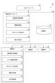
- FIG. 1 is an overall schematic diagram of an automated guided vehicle system to which the path generation system of the present disclosure is applied.
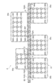
- FIG. 2(a) is a diagram showing a travel area (travel route), and FIG. 2(b) is a diagram showing one unit thereof.
- FIG. 3 is a functional block diagram showing the functional configuration of a controller according to an embodiment.
- FIG. 4 is a diagram for explaining a plurality of first blocks and one second block set by the controller.
- FIG. 5 is a diagram for explaining areas searched by the controller when generating a route.
- FIG. 6 is a diagram showing a travel area and first and second blocks according to the first modified example.
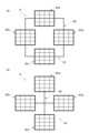
- 7(a) and 7(b) are diagrams showing a travel area and first and second blocks according to second and third modified examples, respectively.
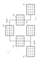
- 8(a) and 8(b) are diagrams showing a travel area and first and second blocks according to the fourth and fifth modified examples, respectively.
- FIG. 9 is a diagram showing a travel area and first and second blocks according to
- the automated guided vehicle system 1 is, for example, a transport system that transports items within a building 100.
- the automated guided vehicle system 1 includes a plurality of automated guided vehicles 10 that transport items, and a travel area A in which the automated guided vehicles 10 travel.
- three processing devices first processing device 31, second processing device 32, and third processing device 33
- an unloading station 34 and a carrying-in station 35 are provided within the building 100.
- the travel area A is provided in an area excluding the first processing device 31 to the third processing device 3, and the unloading station 34 and the carrying-in station 35.
- the items handled in the automated guided vehicle system 1 may be parts or products that can be transported by each automated guided vehicle 10, and are not particularly limited.
- the automated guided vehicle system 1 will be abbreviated as “guided vehicle system 1"
- the automated guided vehicle 10 will be abbreviated as “guided vehicle 10”.
- the transport vehicle system 1 may also include one or more automated warehouses (not shown) for storing multiple items.
- the automated warehouse may have storage shelves capable of loading multiple items, a stacker crane for transferring items to the storage shelves, and multiple entry/exit ports to which items can be transferred by the transport vehicle 10 (none of which are shown).
- the number and arrangement of the processing devices, and the travel area A may be freely determined and are not limited to the example shown in FIG. 1.
- the transport vehicle 10 travels autonomously along a preset route 2.
- the transport vehicle 10 is, for example, an AGV (Automated Guided Vehicle).
- the travel area A is a two-dimensional area on the floor surface (travel surface) and is an area in which each transport vehicle 10 can travel.
- the travel area A has a large number (plurality) of points P where each transport vehicle 10 can pass and stop, and a plurality of segments (paths) S provided between these points P (specifically, between two adjacent points P) and connecting these points P.
- Each point P may be provided with a code such as a barcode or a two-dimensional code so that the travel control unit 15 of each transport vehicle 10 can detect the position of the vehicle.
- Each transport vehicle 10 has a reading device (not shown).
- each transport vehicle 10 detects the position of the vehicle by reading information from the two-dimensional code.
- the two-dimensional code may include information for identifying the direction.
- the two-dimensional code may not include information for identifying the direction, and each transport vehicle 10 may have a direction detection means such as a compass for identifying the direction of the vehicle (direction of travel).
- the transport vehicle 10 may travel while detecting magnetic signals output from a magnetic tape or a magnetic marker.
- the transport vehicle 10 may generate light from a laser or the like and detect the reflected light reflected by a mirror attached to the wall of a building, etc., to detect its own position while traveling, or may detect its own position using information from a GPS, etc.
- SLAM Simultaneous Localization and Mapping
- the transport vehicle system 1 may be provided with a charging point or charging station for supplying power to the transport vehicle 10.
- Each linear segment S shown by a dashed line in the figure has a length equivalent to the distance (pitch) between two points P, i.e., the section length.
- the section length in each segment S may be constant in the travel area A, but it does not have to be constant.
- the section length in some segments S may be longer than the (average) section length in many other segments S, or conversely, it may be shorter.
- an upper limit is set on the length of the segment S, i.e., the section length, to achieve stable travel.
- the upper limit on the section length is, for example, about 1000 mm to 3000 mm.
- each point P is associated with a spin turn time (seconds) as information necessary for searching and generating a travel route for the transport vehicle 10.
- the spin turn time (seconds) is set to a specific time (turn time) for two cases: when the transport vehicle 10 stops at the point P and makes a 90-degree spin turn, and when the transport vehicle 10 makes a 180-degree spin turn.
- Each segment S is also associated with a section length (mm) and a travel speed (mm/second). From these two pieces of information, the time it takes for the transport vehicle 10 to travel the segment S (travel time) is calculated.
- These turn times and travel times are indices used in the route search process by the route generation unit 14 described later, and are also "costs" from another perspective.
- Each point P may also be called a "stop point.”
- the guided vehicle system 1 includes a route generation system 6 that generates a travel route R for each of the multiple guided vehicles 10 to travel from a starting point P from to a destination P to in a travel area A.
- a route generation system 6 that generates a travel route R for each of the multiple guided vehicles 10 to travel from a starting point P from to a destination P to in a travel area A.
- Each of the starting point P from and the destination P to is any two points P in the travel area A.
- the route generation system 6 includes a plurality of transport vehicles 10 that transport items, a transport vehicle controller 20 that controls the plurality of transport vehicles 10, and a host controller 5 that issues transport requests to the transport vehicle controller 20.
- the transport vehicle 10 executes travel control and loading/unloading control for transporting an article from a starting point P from to a destination P to .
- the transport vehicle controller 20 and the transport vehicle 10 cooperate to generate a travel route R from the starting point P from to the destination P to . That is, the controller function for generating the travel route R is distributed to the transport vehicle controller 20 and the transport vehicle 10.
- the lifter of the transport vehicle 10 is raised and lowered to load the article from each processing device or transfer station onto the transport vehicle 10, and unload the article from the transport vehicle 10 to each processing device or transfer station.
- the transport vehicle controller 20 is a control device that manages multiple transport vehicles 10.
- the transport vehicle controller 20 is a computer having a ROM (Read Only Memory) in which programs and the like are stored, a RAM (Random Access Memory) for temporarily storing data, a storage medium such as a HDD (Hard Disk Drive), a processor such as a CPU (Central Processing Unit), and a communication circuit such as a wireless LAN.
- the transport vehicle controller 20 can be configured as software in which a program stored in the ROM is loaded onto the RAM and executed by the CPU, for example.
- the transport vehicle controller 20 may be configured as hardware using electronic circuits and the like.
- the transport vehicle controller 20 may be configured as one device or multiple devices. When configured as multiple devices, these are connected via a communication network such as the Internet or an intranet to logically construct a single transport vehicle controller 20.
- the transport vehicle controller 20 is connected to the transport vehicle 10 and the upper controller 5 by wire or wirelessly.
- the transport vehicle controller 20 receives information from the transport vehicle 10 regarding the current position and current speed of the transport vehicle 10.
- the transport vehicle controller 20 receives a transport request from the upper controller 5 to transport an item from one processing device to another.
- a transport request is generated, for example, when an item arrives at the end of the outgoing conveyor, or when an item arrives at the dispensing station after processing in upstream equipment is completed.
- the transport vehicle controller 20 generates a transport command in response to the received transport request and assigns the transport command to the transport vehicle 10.
- the transport command is a control command for transporting an item by the transport vehicle 10 from the source transfer station in the transport request to the destination transfer station.
- the transport command includes information regarding the transfer of the item at the source transfer station, travel along the route 2 from the source transfer station to the destination transfer station, and the transfer of the item at the destination transfer station.
- the transport vehicle controller 20 has a transport request receiving unit 21, an information acquiring unit 23, a first block setting unit 24, an allocation determining unit 25, and a storage unit 27.
- the transport request receiving unit 21 receives a transport request from the upper controller 5 and generates a transport command in response to the received transport request.
- the information acquiring unit 23 acquires information about the travel area A and information about the travel state of all transport vehicles 10.
- the allocation determining unit 25 assigns an empty transport vehicle (empty unmanned transport vehicle), which is a transport vehicle 10 that is not executing another transport request, to the transport request.
- the first block setting unit 24 will be described later.
- the storage unit 27 stores information about the divided blocks B1a to B1e (first blocks; see FIG. 4) set by the first block setting unit 24 for the travel area A.
- the transport vehicle 10 has a transport command receiving unit 11, an area information acquiring unit 12, a second block setting unit 13, a route generating unit 14, and a travel control unit 15 as functions related to the travel control of the vehicle itself.
- the transport command receiving unit 11, the area information acquiring unit 12, the second block setting unit 13, the route generating unit 14, and the travel control unit 15 are also configured to include storage media such as ROM, RAM, and HDD, processors such as CPU, and communication circuits such as wireless LAN.
- the transport command receiving unit 11 receives a transport command transmitted from the allocation determination unit 25 of the transport vehicle controller 20.
- the area information acquiring unit 12 acquires information related to the travel area A.
- the information acquired by the information acquiring unit 23 of the transport vehicle controller 20 and the area information acquiring unit 12 of the transport vehicle 10 includes information related to each point P and each segment S described above.
- the second block setting unit 13 will be described later.
- the route generation unit 14 generates a driving route R for the vehicle based on the divided blocks B1a to B1e set by the first block setting unit 24 and the shared block B2 set by the second block setting unit 13.
- the route generation system 6 When generating the travel route R for each transport vehicle 10 that is to execute a transport request, the route generation system 6 does not subject all points P in the travel area A to route search, but rather subjects only some of the points P to route search.
- the first block setting unit 24 of the transport vehicle controller 20 sets three or more divided blocks B1a to B1e for all points P in the travel area A. For example, five divided blocks B1a to B1e exist to divide the travel area A.
- An upper limit is set for the number of points P included in each of the divided blocks B1a to B1e.
- the upper limit number of points P that can be included in each divided block may be set to less than 50, less than 100, or less than 200, for example. It may be determined according to the size of the travel area A.
- the upper limit number may be determined according to the computing power or performance of the memory in the transport vehicle controller 20.
- the number of divided blocks is not particularly limited, but in the example shown in FIG. 4, the divided blocks are set so that the number of points P included in each divided block is approximately 9 to 17.
- the multiple division blocks are set based on the loading station and unloading station of each processing device, so that multiple points around them belong to one division block.
- the second block setting unit 13 of the transport vehicle 10 sets a shared block (second block) B2 to include a point P with a high passing frequency based on a simulation of all transport patterns as a preparation for the route generation unit 14 to generate the travel route R.
- the shared block B2 is connected to the divided blocks B1a to B1e via multiple segments S.
- first block setting unit 24 of the transport vehicle controller 20 may set the divided blocks B1a to B1e by dividing the area other than the shared block B2 after the shared block B2 is set by the second block setting unit 13.
- the divided block (first block) and the shared block (second block) are set separately.
- FIG. 4 shows block setting X1 in this embodiment.
- points P included in shared block B2 are assigned numbers from 3000 to 3100.
- Points P included in divided blocks B1a to B1e are assigned numbers other than 3000 to 3100.
- divided block B1a is assigned numbers from 3201 to 3300
- divided block B1b is assigned numbers from 3301 to 3500
- divided block B1c is assigned numbers from 3501 to 3700
- divided block B1d is assigned numbers from 3701 to 3900
- divided block B1e is assigned numbers from 3901 to 4100.
- the shared block B2 includes a plurality of points P, each of which is connected to only three or fewer segments S.
- the shared block B2 includes a plurality of points P, each of which is connected to only three or fewer segments S.
- the shared block B2 includes a first type point P1, which is connected to only one segment S, a second type point P2, which is connected to only two segments S, and a third type point P3, which is connected to only three segments S.
- the shared block B2 is set as an area that must be passed through in order to travel between different divided blocks.
- the route generating unit 14 of the transportation vehicle 10 extracts divided block B1b (source block) to which the starting point P from (No. 3304) belongs, divided block B1e (destination block) to which the destination P to (No. 4001) belongs, and point P included in the shared block B from among divided blocks B1a to B1e, and generates a travel route R from among them.
- the route generating unit 14 finds the shortest route by using a known method such as the Dijkstra algorithm as a route search algorithm.
- the Dijkstra algorithm always finds the shortest route.
- Other divided blocks are not used in the route search (they are treated as if they do not exist).
- the route generation unit 14 generates a travel route R indicated by a thick arrow in FIG. 5.
- the travel route R is made up of a source route R1b generated in the divided block B1b, a shared route R2 generated in the shared block B2, and a destination route R1e generated in the divided block B1e.
- the setting of three or more divided blocks (first blocks) and the setting of one or more shared blocks (second blocks) may be performed offline when creating the map data.
- the travel control unit 15 causes the transport vehicle 10 to travel along the travel route R generated by the route generation unit 14.
- the first block setting unit 24 sets the divided blocks B1a to B1e divided into three or more, and the second block setting unit 13 sets the shared block B2. That is, all points P in the travel area A are divided into any of these blocks.
- the route generation unit 14 extracts points P included in the divided block B1b (transport source block) to which the starting point P from belongs, the divided block B1e (transport destination block) to which the destination P to belongs, and the shared block B from among the divided blocks B1a to B1e, and generates a travel route R from among them.
- the area (points P) searched by the route generation unit 14 during route generation is narrowed down (limited) to a part of the travel area A rather than the entirety (all points). This reduces the load required for route generation even in a vast travel area A.
- the shared block B2 is set to include points P that are frequently passed through, based on a simulation of all transport patterns. This allows the shared block B2 to be set appropriately to suit the actual environment.
- the second block setting unit 13 sets a shared block B2 individually for the travel route R on which each transport vehicle 10 travels. By changing the shared block B2 for each transport vehicle 10, the frequency of interference between transport vehicles 10 can be reduced.
- An upper limit is set for the number of points P contained in each of the divided blocks B1a to B1e. This reduces the number of areas (points P) that the route generation unit 14 searches when generating a route, further reducing the load required for route generation.
- the present invention is not limited to the above embodiments.
- three or more divided blocks (first blocks) and one or more shared blocks (second blocks) may be set in different manners.
- five divided blocks B1a to B1e are formed into an L-shaped block overall and are connected to each other, and a single shared block B2 may be set that connects the centers of the five divided blocks in an L-shaped line.
- the shared block B2 includes multiple points P, each of which is connected to four or more segments S. While one transport vehicle 10 sets such a shared block B2, another transport vehicle 10 may set a different shared block (for example, a block that is shifted in position from the shared block B2 in FIG. 6). Note that in FIG. 6 and subsequent figures, the points P are not shown, and the positions of the points P are expressed as lattice points.
- a single shared block B2 may connect four divided blocks B1a to B1d.
- a cross-shaped shared block B2 may connect four divided blocks B1a to B1d.
- block settings X3 and X4 may be combined to connect each divided block to all other divided blocks with shared blocks B2a and B2b.
- block setting X6 shown in FIG. 8(b) only some divided blocks may be connected to all other divided blocks with shared blocks B2a and B2b.
- shared block B2a may connect divided blocks B1a and B1b, and this may serve as the base for shared block B2b to connect four divided blocks B1c to B1f.
- the transportation vehicle controller 20 and the transportation vehicle 10 cooperate to generate the travel route R from the starting point P from to the destination P to .
- the transportation vehicle controller 20 only a controller provided in the transportation vehicle 10, or only a controller provided separately from the transportation vehicle controller 20 and the transportation vehicle 10 may generate the travel route R.
- the transportation vehicle controller 20 and another controller may cooperate to generate the travel route R, or the controller provided in the transportation vehicle 10 and another controller may cooperate to generate the travel route R.
- the transport vehicle system 1 may include only one transport vehicle 10, and the route generation system 6 may generate a travel route R for the one transport vehicle 10.
- the transport vehicle 10 is not limited to an AGV, and may be, for example, an overhead traveling vehicle or a tracked vehicle.
- a route generation system that generates a route for one or more transport vehicles to travel from a starting point to a destination in a travel area, a controller that generates the route along which the transport vehicle travels; the travel area has a plurality of points at which the transport vehicle can pass and stop;
- the controller A first block divided into three or more parts and a second block connected to the first block are set for the plurality of points;
- a route generation system that extracts the points included in a source block, which is one of the first blocks to which the departure point belongs, a destination block, which is one of the first blocks to which the destination belongs, and the second block, and generates the route from the extracted points.
- the path generation system according to claim 1 or 2 wherein the controller sets the second block individually for the path on which each of the multiple guided vehicles travels.
- at least one of the plurality of points in the travel area is connected to only three or less paths;
- [6] The route generation system according to any one of [1] to [4], wherein the second block includes a plurality of points, each of which has four or more passages connected thereto.
Landscapes
- Engineering & Computer Science (AREA)
- Aviation & Aerospace Engineering (AREA)
- Radar, Positioning & Navigation (AREA)
- Remote Sensing (AREA)
- Physics & Mathematics (AREA)
- General Physics & Mathematics (AREA)
- Automation & Control Theory (AREA)
- Control Of Position, Course, Altitude, Or Attitude Of Moving Bodies (AREA)
Abstract
経路生成システムは、搬送車が走行エリアにおいて出発地から目的地まで走行する経路を生成するコントローラを備える。コントローラは、走行エリアの複数のポイントに対し、3つ以上に分かれた第1のブロックと、第1のブロックに接続された第2のブロックとを設定し、第1のブロックのうち出発地が属する1つの第1のブロックである搬送元ブロック、第1のブロックのうち目的地が属する1つの第1のブロックである搬送先ブロック、及び第2のブロックに含まれるポイントを抽出し、抽出したポイントの中から経路を生成する。
Description
本開示は、搬送車の走行経路を生成する経路生成システムに関する。
従来、複数の自動無人搬送車(AGV:Automated Guided Vehicle)が初期地点から搬送先地点(目的地)まで走行するにあたり、搬送車の総搬送時間又は総搬送距離を最短とする経路計画を短時間で作成する経路計画装置及び搬送システムが知られている(例えば、特許文献1参照)。
上記した従来のシステムは、すべての搬送車の経路計画を短い計算時間で作成するが、走行エリアが広くなった場合には、経路計画の計算が膨大となる。従来のシステムではこの点が考慮されておらず、広大な走行エリアにおける経路計画では多大な計算負荷を要する。場合によっては、経路の探索に用いるメモリ量が使用可能なメモリ量の上限に達してしまい、経路の生成が不可能となる可能性もある。
本開示は、広大な走行エリアにおいても経路生成に要する負荷を軽減できる経路生成システムを説明する。
本開示の一態様は、1つ又は複数の搬送車が走行エリアにおいて出発地から目的地まで走行するための経路を生成する経路生成システムであって、搬送車が走行する経路を生成するコントローラを備え、走行エリアは、搬送車が通過及び停止できる複数のポイントを有し、コントローラは、複数のポイントに対し、3つ以上に分かれた第1のブロックと、第1のブロックに接続された第2のブロックとを設定し、第1のブロックのうち出発地が属する1つの第1のブロックである搬送元ブロック、第1のブロックのうち目的地が属する1つの第1のブロックである搬送先ブロック、及び第2のブロックに含まれるポイントを抽出し、抽出したポイントの中から経路を生成する。
この経路生成システムによれば、コントローラによって、3つ以上に分かれた第1のブロックと、それらに接続される第2のブロックとが設定される。すなわち、走行エリアの複数のポイントが、これらの何れかのブロックに分けられる。コントローラによって、3つ以上の第1のブロックのうちの搬送元ブロックと搬送先ブロック、及び、第2のブロックとに含まれるポイントが抽出され、それらの中から経路が生成される。このように、経路生成時にコントローラが探索するエリア(ポイント)が、走行エリアの全体(全ポイント)ではなく一部に絞られる(限定される)。これにより、広大な走行エリアにおいても経路生成に要する負荷を軽減できる。
第2のブロックは、全搬送パターンのシミュレーションに基づいて、通過頻度の高いポイントを含むように設定されてもよい。この場合、実環境に合わせて適切に第2のブロックを設定することができる。
コントローラは、複数の搬送車のそれぞれが走行する経路について個別に第2のブロックを設定してもよい。第2のブロックを搬送車毎に変えることで、搬送車同士の干渉が発生する頻度を抑えることができる。
第1のブロックのそれぞれに含まれるポイントの個数には上限が設定されていてもよい。この場合、経路生成時にコントローラが探索するエリア(ポイント)の個数が減るので、経路生成に要する負荷を更に軽減できる。
走行エリア内の複数のポイントのうち少なくとも1つのポイントには、3つ以下の通路のみが接続されており、第2のブロックは、当該少なくとも1つのポイントを含んでもよい。
第2のブロックは、それぞれ4つ以上の通路が接続された複数のポイントを含んでもよい。
本開示によれば、広大な走行エリアにおいても経路生成に要する負荷を軽減できる。
以下、本開示の実施形態について、図面を参照しながら説明する。なお、図面の説明において同一要素には同一符号を付し、重複する説明は省略する。
まず図1を参照して、本実施形態の経路生成システム6(図3参照)が適用される無人搬送車システム1について説明する。図1に示されるように、無人搬送車システム1は、例えば、建屋100内において物品の搬送等を行う搬送システムである。無人搬送車システム1は、物品を搬送する複数の無人搬送車10と、無人搬送車10が走行する走行エリアAとを備える。図1に示される例では、建屋100内に、例えば、3つの処理装置(第1処理装置31、第2処理装置32、及び第3処理装置33)と、搬出ステーション34及び搬入ステーション35とが設けられている。走行エリアAは、第1処理装置31~第3処理装置3、及び、搬出ステーション34及び搬入ステーション35を除く領域に設けられている。無人搬送車システム1において扱われる物品は、各無人搬送車10によって搬送可能な部品又は商品等であればよく、特に限定されない。以下、無人搬送車システム1は「搬送車システム1」と略称され、無人搬送車10は「搬送車10」と略称される。
搬送車システム1において、第1処理装置31~第3処理装置3、及び、搬出ステーション34及び搬入ステーション35のそれぞれは、走行エリアA内の所定の経路に沿って走行する搬送車10によって、物品を移載可能に配置されている。搬送車システム1が、複数の物品を保管する1つ又は複数の自動倉庫(図示せず)を備えてもよい。自動倉庫は、複数の物品を載置可能な保管棚と、保管棚に対して物品を移載するスタッカクレーンと、搬送車10によって物品が移載可能な複数の出入ポートと、を有してもよい(何れも図示せず)。処理装置の個数と配置、及び走行エリアAは、自由に決められてよく、図1に示される例に限定されない。
搬送車10は、予め設定された経路2に沿って自律的に走行する。搬送車10は、例えば、AGV(Automated Guided Vehicle)である。
図2(a)及び図2(b)を参照して、走行エリアAの構成について説明する。走行エリアAは、床面上(走行面上)において二次元状に広がる領域であり、各搬送車10が走行可能な領域である。走行エリアAは、各搬送車10が通過及び停止できる多数の(複数の)ポイントPと、これらのポイントPの間(詳細には、隣り合う2つのポイントP)の間に設けられてこれらのポイントPを接続する複数のセグメント(通路)Sとを有する。各ポイントPには、各搬送車10の走行制御部15が自車の位置を検出できるよう、バーコード又は二次元コード等のコードが設けられてもよい。各搬送車10は、読取装置(図示せず)を有する。二次元コードが設けられる場合、各搬送車10は、二次元コードから情報を読み取ることで自車の位置を検出する。二次元コードに、方向を特定するための情報が含まれてもよい。或いは、二次元コードに方向を特定するための情報が含まれず、各搬送車10が、自車の向き(走行する向き)を特定するためのコンパス等の向き検出手段を有してもよい。
なお、搬送車10は、磁気テープ又は磁気マーカー等から出力される磁気信号等を検出しながら走行してもよい。或いは、搬送車10は、レーザ等から光を発生させ、建屋の壁部等に取り付けられたミラーにて反射した反射光を検出することで自己位置を検出しながら走行してもよいし、GPS等の情報を利用することで自己位置を検出しながら走行してもよい。搬送車10に対する誘導方式として、SLAM(Simultaneous Localization and Mapping)技術が用いられてもよい。搬送車システム1が、搬送車10に電力を供給するための充電ポイント又は充電ステーション等が設けられてもよい。
図において破線で示される直線状の各セグメントSは、2つのポイントP間の距離(ピッチ)に相当する長さ、すなわち区間長を有する。各セグメントSにおける区間長は、走行エリアAにおいて一定でもよいが、一定でなくてもよい。一部のセグメントSにおける区間長が、他の多くのセグメントSにおける(平均的な)区間長よりも長くなっていてもよく、逆に短くなっていてもよい。搬送車システム1では、安定した走行を実現するため、例えば、セグメントSの長さすなわち区間長に上限が設定されている。区間長に上限は、例えば、1000mm~3000mm程度である。
図2(b)に示されるように、搬送車10の走行経路の探索及び生成に必要な情報として、各ポイントPには、スピンターン時間(秒)が紐づけられている。スピンターン時間(秒)では、搬送車10がポイントP上で停止して90度スピンターンする場合、及び、180度スピンターンする場合の2通りに関して固有の時間(ターン時間)が設定されている。また各セグメントSには、区間長(mm)と走行速度(mm/秒)が紐づけられている。これら2つの情報から、搬送車10が当該セグメントSを走行するのにかかる時間(走行時間)が算出される。これらのターン時間及び走行時間は、後述する経路生成部14による経路探索の処理に用いられる指標であり、別の観点では「コスト」である。なお、各ポイントPは、「停止ポイント」と称されてもよい。
図3に示されるように、搬送車システム1は、複数の搬送車10のそれぞれが走行エリアAにおいて出発地Pfromから目的地Ptoまで走行するための走行経路Rを生成する経路生成システム6を備えている。出発地Pfrom及び目的地Ptoのそれぞれは、走行エリアA内の何れか2つのポイントPである。
図3に示されるように、経路生成システム6は、物品を搬送する複数の搬送車10と、複数の搬送車10を制御する搬送車コントローラ20と、搬送車コントローラ20に対して搬送要求を与える上位コントローラ5とを備える。
搬送車10は、搬送車コントローラ20から搬送指令(後述)が割り当てられた場合、出発地Pfromから目的地Ptoへと物品を搬送させるための走行制御及び荷積み荷下ろし制御を実行する。経路生成システム6では、搬送車コントローラ20及び搬送車10が協働して、出発地Pfromから目的地Ptoへの走行経路Rを生成する。すなわち、走行経路Rを生成するコントローラの機能が、搬送車コントローラ20と搬送車10に分散している。荷積み荷下ろし制御では、搬送車10が有するリフターを上昇及び下降させることで、各処理装置又は移載ステーションから搬送車10への荷積みを実施し、搬送車10から各処理装置又は移載ステーションへの荷下ろしを実施する。
搬送車コントローラ20は、複数の搬送車10を管理する制御装置である。搬送車コントローラ20は、プログラム等が記憶されたROM(Read Only Memory)、データを一時的に記憶するRAM(Random AccessMemory)、HDD(Hard Disk Drive)等の記憶媒体、CPU(Central Processing Unit)等のプロセッサ、及び、無線LAN等の通信回路等を有するコンピュータである。搬送車コントローラ20は、例えばROMに格納されているプログラムがRAM上にロードされてCPUで実行されるソフトウェアとして構成することができる。搬送車コントローラ20は、電子回路等によるハードウェアとして構成されてもよい。搬送車コントローラ20は、一つの装置で構成されてもよいし、複数の装置で構成されてもよい。複数の装置で構成されている場合には、これらがインターネット又はイントラネット等の通信ネットワークを介して接続されることで、論理的に一つの搬送車コントローラ20が構築される。
搬送車コントローラ20は、搬送車10及び上位コントローラ5と、有線又は無線により接続されている。搬送車コントローラ20は、搬送車10から当該搬送車10の現在位置及び現在速度等に関する情報を受信する。搬送車コントローラ20は、上位コントローラ5から、ある処理装置から別の処理装置へ物品を搬送させるための搬送要求を受信する。搬送要求とは、例えば、出庫コンベアの先端に物品が到着したこと、又は、上流設備での処理が完了して払い出しステーションに物品が到着したことを契機として発生する。搬送車コントローラ20は、受信した搬送要求に応じて搬送指令を生成し、搬送車10に対して当該搬送指令を割り付ける。
搬送指令は、搬送要求における搬送元の移載ステーションから搬送先の移載ステーションまで物品を搬送車10により搬送させるための制御指令である。搬送指令は、搬送元の移載ステーションにおける物品の移載、搬送元の移載ステーションから搬送先の移載ステーションへの経路2に沿った走行、搬送先の移載ステーションにおける物品の移載に関する情報を含む。
図3に示されるように、搬送車コントローラ20は、搬送要求受信部21と、情報取得部23と、第1ブロック設定部24と、割付決定部25と、記憶部27とを有する。搬送要求受信部21は、上位コントローラ5から搬送要求を受信し、受信した搬送要求に応じて搬送指令を生成する。情報取得部23は、走行エリアAに関する情報を取得すると共に、全搬送車10の走行状態に関する情報を取得する。割付決定部25は、当該搬送要求に対して、他の搬送要求を実行中でない搬送車10である空き搬送車(空きの無人搬送車)を割り付ける。第1ブロック設定部24については後述する。記憶部27は、走行エリアAに対して第1ブロック設定部24が設定した分割ブロックB1a~B1e(第1のブロック。図4参照)に関する情報を記憶する。
搬送車10は、自車の走行制御に係る機能として、搬送指令受信部11と、エリア情報取得部12と、第2ブロック設定部13と、経路生成部14と、走行制御部15とを有する。これらの搬送指令受信部11、エリア情報取得部12、第2ブロック設定部13、経路生成部14、及び走行制御部15も、ROM、RAM、HDD等の記憶媒体、CPU等のプロセッサ、及び、無線LAN等の通信回路等を含んで構成される。搬送指令受信部11は、搬送車コントローラ20の割付決定部25から送信された搬送指令を受信する。エリア情報取得部12は、走行エリアAに関する情報を取得する。搬送車コントローラ20の情報取得部23、及び、搬送車10のエリア情報取得部12によって取得される情報には、上述した各ポイントP及び各セグメントSに関する情報が含まれる。第2ブロック設定部13については後述する。経路生成部14は、第1ブロック設定部24によって設定された分割ブロックB1a~B1eと、第2ブロック設定部13によって設定された共有ブロックB2とに基づいて、自車の走行経路Rを生成する。
続いて、図3、図4及び図5を参照して、経路生成システム6における各ブロックの設定および走行経路Rの生成について説明する。経路生成システム6では、搬送要求を実行しようとする各搬送車10の走行経路Rを生成するにあたり、走行エリアA内のすべてのポイントPを経路探索の対象とするのではなく、一部のみのポイントPを経路探索の対象とする。
図3及び図4に示されるように、搬送車コントローラ20の第1ブロック設定部24は、走行エリアA内のすべてのポイントPに対し、3つ以上に分かれた分割ブロックB1a~B1eを設定する。例えば5つの分割ブロックB1a~B1eが、走行エリアAを分割するように存在する。分割ブロックB1a~B1eのそれぞれに含まれるポイントPの個数には、例えば上限が設定されている。分割ブロック1つ当たりに含まれ得るポイントPの上限個数は、例えば50個未満に設定されてもよいし、100個未満に設定されてもよいし、200個未満に設定されてもよい。走行エリアAの規模に応じて決定されてもよい。上限個数が、搬送車コントローラ20におけるメモリの計算能力又は性能等に応じて決定されてもよい。分割ブロックの個数は、特に限定されないが、図4に示される例では、各分割ブロックに含まれるポイントPの個数が、9個~17個程度となるように、分割ブロックが設定される。複数の分割ブロックは、例えば、各処理装置の搬入ステーション及び搬出ステーションを基準として、その周辺に存在する複数のポイントが1つの分割ブロックに属するように設定される。
搬送車10の第2ブロック設定部13は、経路生成部14が走行経路Rを生成する前準備として、全搬送パターンのシミュレーションに基づいて、通過頻度の高いポイントPを含むように共有ブロック(第2のブロック)B2を設定する。共有ブロックB2は、複数のセグメントSを介して分割ブロックB1a~B1eに接続される。
なお、搬送車コントローラ20の第1ブロック設定部24は、第2ブロック設定部13による共有ブロックB2の設定後に、共有ブロックB2以外の領域を分割することで分割ブロックB1a~B1eを設定してもよい。分割ブロック(第1ブロック)と共有ブロック(第2ブロック)が分けて設定される。
図4には、本実施形態におけるブロック設定X1が示されている。図4に示されるように、現在の搬送指令(搬送要求)において、共有ブロックB2に含まれるポイントPには、3000~3100までの数字が割り当てられる。そして、分割ブロックB1a~B1eに含まれるポイントPには、3000~3100以外の数字が割り当てられる。例えば、分割ブロックB1aには、3201~3300までの数字が割り当てられ、分割ブロックB1bには、3301~3500までの数字が割り当てられ、分割ブロックB1cには、3501~3700までの数字が割り当てられ、分割ブロックB1dには、3701~3900までの数字が割り当てられ、分割ブロックB1eには、3901~4100までの数字が割り当てられる。
図4に示されるように、共有ブロックB2は、それぞれ3つ以下のセグメントSのみが接続された複数のポイントPを含む。特に本実施形態では、共有ブロックB2は、それぞれ3つ以下のセグメントSのみが接続された複数のポイントPのみを含む。例えば、共有ブロックB2には、1つのセグメントSのみが接続された第1種ポイントP1、2つのセグメントSのみが接続された第2種ポイントP2、及び、3つのセグメントSのみが接続された第3種ポイントP3を含む。共有ブロックB2は、異なる分割ブロック間を往来するのに通過することが不可欠なエリアとして設定されている。
そして、図5に示されるように、搬送車10の経路生成部14は、分割ブロックB1a~B1eのうち出発地Pfrom(3304番)が属する分割ブロックB1b(搬送元ブロック)、目的地Pto(4001番)が属する分割ブロックB1e(搬送先ブロック)、及び共有ブロックBに含まれるポイントPが抽出され、それらの中から走行経路Rが生成される。経路生成部14は、経路探索アルゴリズムとして、例えばダイクストラ法などの公知の手法を用いることにより、最短経路を求める。ダイクストラ法によれば、必ず最短経路が求められる。それ以外の分割ブロックは、経路探索には用いられない(存在しないのと同様の扱いがなされる)。
経路探索の結果、経路生成部14は、図5において太線の矢印で示される走行経路Rを生成する。走行経路Rは、分割ブロックB1bにおいて生成された搬送元経路R1bと、共有ブロックB2において生成された共有経路R2と、分割ブロックB1eにおいて生成された搬送先経路R1eと、からなる。
なお、3つ以上の分割ブロック(第1のブロック)の設定、及び、1つ又は複数の共有ブロック(第2のブロック)の設定が、マップデータ作成時にオフラインで行われてもよい。
走行制御部15は、経路生成部14によって生成された走行経路Rに従って、搬送車10を走行させる。
本実施形態の搬送車システム1及び経路生成システム6によれば、第1ブロック設定部24によって、3つ以上に分かれた分割ブロックB1a~B1eが設定され、第2ブロック設定部13によって、共有ブロックB2が設定される。すなわち、走行エリアAのすべてのポイントPが、これらの何れかのブロックに分けられる。経路生成部14によって、分割ブロックB1a~B1eのうち出発地Pfromが属する分割ブロックB1b(搬送元ブロック)、目的地Ptoが属する分割ブロックB1e(搬送先ブロック)、及び共有ブロックBに含まれるポイントPが抽出され、それらの中から走行経路Rが生成される。このように、経路生成時に経路生成部14が探索するエリア(ポイントP)が、走行エリアAの全体(全ポイント)ではなく一部に絞られる(限定される)。これにより、広大な走行エリアAにおいても経路生成に要する負荷を軽減できる。
共有ブロックB2は、全搬送パターンのシミュレーションに基づいて、通過頻度の高いポイントPを含むように設定される。これにより、実環境に合わせて適切に共有ブロックB2を設定することができる。
第2ブロック設定部13は、搬送車10のそれぞれが走行する走行経路Rについて個別に共有ブロックB2を設定する。共有ブロックB2を搬送車10毎に変えることで、搬送車10同士の干渉が発生する頻度を抑えることができる。
分割ブロックB1a~B1eのそれぞれに含まれるポイントPの個数には上限が設定されている。これにより、経路生成時に経路生成部14が探索するエリア(ポイントP)の個数が減るので、経路生成に要する負荷を更に軽減できる。
以上、本開示の実施形態について説明したが、本発明は上記実施形態に限られない。例えば、走行エリアAの構成(ポイントPの個数及び配置、セグメントSの個数、長さ及び配置)、並びに走行エリアAの大きさ(規模)によっては、3つ以上の分割ブロック(第1のブロック)及び1つ又は複数の共有ブロック(第2のブロック)が異なる態様で設定され得る。
例えば、図6に示されるブロック設定X2のように、全体としてL字のブロック状に形成されると共に互いに連結された5つの分割ブロックB1a~B1eにおいて、その中央をL字の線状に接続する一本の共有ブロックB2が設定されてもよい。この場合、共有ブロックB2は、それぞれ4つ以上のセグメントSが接続された複数のポイントPを含む。ある搬送車10がこのような共有ブロックB2を設定する一方で、別の搬送車10が、別の共有ブロック(例えば、図6の共有ブロックB2とは位置のずれたブロック)を設定してもよい。なお、図6以降の各図においては、ポイントPの図示が省略されており、ポイントPの位置が格子点として表現されている。
また、図7(a)に示されるブロック設定X3のように、一本の共有ブロックB2が4つの分割ブロックB1a~B1dを接続してもよい。図7(b)に示されるブロック設定X4のように、十字状の共有ブロックB2が4つの分割ブロックB1a~B1dを接続してもよい。また図8(a)に示されるブロック設定X5のように、ブロック設定X3とX4が組み合わされて、各分割ブロックと他のすべての分割ブロックと共有ブロックB2a,B2bで接続されてもよい。図8(b)に示されるブロック設定X6のように、一部の分割ブロックだけが、他のすべての分割ブロックと共有ブロックB2a,B2bで接続されてもよい。
図9に示されるブロック設定X7のように、共有ブロックB2aが分割ブロックB1a,B1bを接続し、それが基礎部となって共有ブロックB2bが4つの分割ブロックB1c~B1fを接続してもよい。
上記実施形態では、搬送車コントローラ20及び搬送車10が協働して、出発地Pfromから目的地Ptoへの走行経路Rを生成する態様について説明した。しかし、搬送車コントローラ20のみ、又は搬送車10に設けられたコントローラのみ、又は搬送車コントローラ20及び搬送車10とは別に設けられたコントローラのみが、走行経路Rを生成してもよい。搬送車コントローラ20と別のコントローラが協働して走行経路Rを生成してもよく、搬送車10に設けられたコントローラと別のコントローラが協働して走行経路Rを生成してもよい。
搬送車システム1が、1台のみの搬送車10を備えており、経路生成システム6が、その1台の搬送車10の走行経路Rを生成してもよい。搬送車10は、AGVに特に限定されず、例えば天井走行車及び有軌道台車等であってもよい。
本発明の構成要件は以下のとおりに記載され得る。
[1]
1つ又は複数の搬送車が走行エリアにおいて出発地から目的地まで走行するための経路を生成する経路生成システムであって、
前記搬送車が走行する前記経路を生成するコントローラを備え、
前記走行エリアは、前記搬送車が通過及び停止できる複数のポイントを有し、
前記コントローラは、
前記複数のポイントに対し、3つ以上に分かれた第1のブロックと、前記第1のブロックに接続された第2のブロックとを設定し、
前記第1のブロックのうち前記出発地が属する1つの第1のブロックである搬送元ブロック、前記第1のブロックのうち前記目的地が属する1つの第1のブロックである搬送先ブロック、及び前記第2のブロックに含まれる前記ポイントを抽出し、抽出した前記ポイントの中から前記経路を生成する、経路生成システム。
[2]
前記第2のブロックは、全搬送パターンのシミュレーションに基づいて、通過頻度の高いポイントを含むように設定される、[1]に記載の経路生成システム。
[3]
前記コントローラは、複数の前記搬送車のそれぞれが走行する前記経路について個別に前記第2のブロックを設定する、[1]又は[2]に記載の経路生成システム。
[4]
前記第1のブロックのそれぞれに含まれる前記ポイントの個数には上限が設定されている、[1]~[3]の何れか1つに記載の経路生成システム。
[5]
前記走行エリア内の前記複数のポイントのうち少なくとも1つのポイントには、3つ以下の通路のみが接続されており、
前記第2のブロックは、当該少なくとも1つのポイントを含む、[1]~[4]の何れか1つに記載の経路生成システム。
[6]
前記第2のブロックは、それぞれ4つ以上の通路が接続された複数のポイントを含む、[1]~[4]の何れか1つに記載の経路生成システム。
[1]
1つ又は複数の搬送車が走行エリアにおいて出発地から目的地まで走行するための経路を生成する経路生成システムであって、
前記搬送車が走行する前記経路を生成するコントローラを備え、
前記走行エリアは、前記搬送車が通過及び停止できる複数のポイントを有し、
前記コントローラは、
前記複数のポイントに対し、3つ以上に分かれた第1のブロックと、前記第1のブロックに接続された第2のブロックとを設定し、
前記第1のブロックのうち前記出発地が属する1つの第1のブロックである搬送元ブロック、前記第1のブロックのうち前記目的地が属する1つの第1のブロックである搬送先ブロック、及び前記第2のブロックに含まれる前記ポイントを抽出し、抽出した前記ポイントの中から前記経路を生成する、経路生成システム。
[2]
前記第2のブロックは、全搬送パターンのシミュレーションに基づいて、通過頻度の高いポイントを含むように設定される、[1]に記載の経路生成システム。
[3]
前記コントローラは、複数の前記搬送車のそれぞれが走行する前記経路について個別に前記第2のブロックを設定する、[1]又は[2]に記載の経路生成システム。
[4]
前記第1のブロックのそれぞれに含まれる前記ポイントの個数には上限が設定されている、[1]~[3]の何れか1つに記載の経路生成システム。
[5]
前記走行エリア内の前記複数のポイントのうち少なくとも1つのポイントには、3つ以下の通路のみが接続されており、
前記第2のブロックは、当該少なくとも1つのポイントを含む、[1]~[4]の何れか1つに記載の経路生成システム。
[6]
前記第2のブロックは、それぞれ4つ以上の通路が接続された複数のポイントを含む、[1]~[4]の何れか1つに記載の経路生成システム。
1…搬送車システム(無人搬送車システム)、5…上位コントローラ、6…経路生成システム、10…搬送車(無人搬送車)、11…搬送指令受信部、12…エリア情報取得部、13…第2ブロック設定部、14…経路生成部、15…走行制御部、20…搬送車コントローラ、21…搬送要求受信部、23…情報取得部、24…第1ブロック設定部、25…割付決定部、A…走行エリア、B1a,B1b,B1c,B1d,B1e,B1f,…分割ブロック(第1のブロック)、B2…共有ブロック(第2のブロック)、P…ポイント、Pfrom…出発地、Pto…目的地、R…走行経路、R1b…搬送元経路、R1e…搬送先経路、R2…共有経路、S…セグメント(通路)。
Claims (6)
- 1つ又は複数の搬送車が走行エリアにおいて出発地から目的地まで走行するための経路を生成する経路生成システムであって、
前記搬送車が走行する前記経路を生成するコントローラを備え、
前記走行エリアは、前記搬送車が通過及び停止できる複数のポイントを有し、
前記コントローラは、
前記複数のポイントに対し、3つ以上に分かれた第1のブロックと、前記第1のブロックに接続された第2のブロックとを設定し、
前記第1のブロックのうち前記出発地が属する1つの第1のブロックである搬送元ブロック、前記第1のブロックのうち前記目的地が属する1つの第1のブロックである搬送先ブロック、及び前記第2のブロックに含まれる前記ポイントを抽出し、抽出した前記ポイントの中から前記経路を生成する、経路生成システム。 - 前記第2のブロックは、全搬送パターンのシミュレーションに基づいて、通過頻度の高いポイントを含むように設定される、請求項1に記載の経路生成システム。
- 前記コントローラは、複数の前記搬送車のそれぞれが走行する前記経路について個別に前記第2のブロックを設定する、請求項1又は2に記載の経路生成システム。
- 前記第1のブロックのそれぞれに含まれる前記ポイントの個数には上限が設定されている、請求項1又は2に記載の経路生成システム。
- 前記走行エリア内の前記複数のポイントのうち少なくとも1つのポイントには、3つ以下の通路のみが接続されており、
前記第2のブロックは、当該少なくとも1つのポイントを含む、請求項1又は2に記載の経路生成システム。 - 前記第2のブロックは、それぞれ4つ以上の通路が接続された複数のポイントを含む、請求項1又は2に記載の経路生成システム。
Priority Applications (1)
| Application Number | Priority Date | Filing Date | Title |
|---|---|---|---|
| JP2025527499A JPWO2024257464A1 (ja) | 2023-06-14 | 2024-04-11 |
Applications Claiming Priority (2)
| Application Number | Priority Date | Filing Date | Title |
|---|---|---|---|
| JP2023097995 | 2023-06-14 | ||
| JP2023-097995 | 2023-06-14 |
Publications (1)
| Publication Number | Publication Date |
|---|---|
| WO2024257464A1 true WO2024257464A1 (ja) | 2024-12-19 |
Family
ID=93851910
Family Applications (1)
| Application Number | Title | Priority Date | Filing Date |
|---|---|---|---|
| PCT/JP2024/014690 Ceased WO2024257464A1 (ja) | 2023-06-14 | 2024-04-11 | 経路生成システム |
Country Status (3)
| Country | Link |
|---|---|
| JP (1) | JPWO2024257464A1 (ja) |
| TW (1) | TW202501192A (ja) |
| WO (1) | WO2024257464A1 (ja) |
Citations (4)
| Publication number | Priority date | Publication date | Assignee | Title |
|---|---|---|---|---|
| JP2009053849A (ja) * | 2007-08-24 | 2009-03-12 | Toyota Motor Corp | 経路探索システム、経路探索方法、及び自律移動体 |
| JP2022047944A (ja) * | 2020-09-14 | 2022-03-25 | 株式会社東芝 | 情報処理装置、情報処理方法、コンピュータプログラム及び走行管理システム |
| KR20220135138A (ko) * | 2021-03-29 | 2022-10-06 | 네이버랩스 주식회사 | 실내 공간에 배치된 설비를 이용하는 복수의 로봇이 주행하는 건물 |
| JP2022166112A (ja) * | 2021-04-20 | 2022-11-01 | 三菱電機株式会社 | 経路生成方法、運行管理方法および移動体の制御方法、並びにプログラム |
-
2024
- 2024-04-11 JP JP2025527499A patent/JPWO2024257464A1/ja active Pending
- 2024-04-11 WO PCT/JP2024/014690 patent/WO2024257464A1/ja not_active Ceased
- 2024-06-06 TW TW113120990A patent/TW202501192A/zh unknown
Patent Citations (4)
| Publication number | Priority date | Publication date | Assignee | Title |
|---|---|---|---|---|
| JP2009053849A (ja) * | 2007-08-24 | 2009-03-12 | Toyota Motor Corp | 経路探索システム、経路探索方法、及び自律移動体 |
| JP2022047944A (ja) * | 2020-09-14 | 2022-03-25 | 株式会社東芝 | 情報処理装置、情報処理方法、コンピュータプログラム及び走行管理システム |
| KR20220135138A (ko) * | 2021-03-29 | 2022-10-06 | 네이버랩스 주식회사 | 실내 공간에 배치된 설비를 이용하는 복수의 로봇이 주행하는 건물 |
| JP2022166112A (ja) * | 2021-04-20 | 2022-11-01 | 三菱電機株式会社 | 経路生成方法、運行管理方法および移動体の制御方法、並びにプログラム |
Also Published As
| Publication number | Publication date |
|---|---|
| TW202501192A (zh) | 2025-01-01 |
| JPWO2024257464A1 (ja) | 2024-12-19 |
Similar Documents
| Publication | Publication Date | Title |
|---|---|---|
| JP7397181B2 (ja) | 無人搬送車を制御するための方法および装置 | |
| JP6889802B2 (ja) | 搬送方法、搬送装置および搬送システム | |
| Ellithy et al. | AGV and Industry 4.0 in warehouses: a comprehensive analysis of existing literature and an innovative framework for flexible automation | |
| CN107636547B (zh) | 用于装卸货物的设备和方法 | |
| CN110356760B (zh) | 基于搬运机器人的控制方法和装置 | |
| JP6810772B2 (ja) | 入出荷支援システム、入出荷支援方法及び無人搬送車 | |
| JP7511598B2 (ja) | 情報処理方法、情報処理装置及びプログラム | |
| JP2020190915A (ja) | 走行決定方法、コントローラ、及び当該コントローラを備える走行システム | |
| WO2022244422A1 (ja) | 走行経路設定装置およびこれを備える自律移動ロボット制御システム、走行経路設定方法、並びに走行経路設定プログラム | |
| US20250117011A1 (en) | Robotic vehicle navigaton system and method | |
| JP2022139772A (ja) | 制御装置、及び搬送システム | |
| JPH04340607A (ja) | 最適経路決定装置 | |
| US12299610B2 (en) | Optimized task generation and scheduling of automated guided carts using overhead sensor systems | |
| TW202501192A (zh) | 路徑產生系統 | |
| KR20240020664A (ko) | 반송 시스템, 반송 시스템의 제어 방법 및 기록 매체 | |
| JP3355347B2 (ja) | 搬送システム | |
| KR102963125B1 (ko) | 화물 이송 방법 | |
| JP7861573B2 (ja) | 搬送車システム | |
| JP7514874B2 (ja) | 情報処理方法、情報処理装置及びプログラム | |
| JP2026046699A (ja) | 移動体管理システム、移動体管理方法、及びプログラム | |
| KR20250060475A (ko) | 화물 이송 방법 | |
| CN121115769A (zh) | 路径规划方法、电子设备及计算机可读存储介质 | |
| JP2025030986A (ja) | 走行システム、走行方法、及び走行プログラム | |
| JP2025030985A (ja) | 走行システム、走行方法、及び走行プログラム | |
| JP2025030987A (ja) | 走行システム、走行方法、及び走行プログラム |
Legal Events
| Date | Code | Title | Description |
|---|---|---|---|
| 121 | Ep: the epo has been informed by wipo that ep was designated in this application |
Ref document number: 24821252 Country of ref document: EP Kind code of ref document: A1 |
|
| ENP | Entry into the national phase |
Ref document number: 2025527499 Country of ref document: JP Kind code of ref document: A |
|
| WWE | Wipo information: entry into national phase |
Ref document number: 2025527499 Country of ref document: JP |
|
| NENP | Non-entry into the national phase |
Ref country code: DE |