WO2024257423A1 - 加工機および加工方法 - Google Patents
加工機および加工方法 Download PDFInfo
- Publication number
- WO2024257423A1 WO2024257423A1 PCT/JP2024/009304 JP2024009304W WO2024257423A1 WO 2024257423 A1 WO2024257423 A1 WO 2024257423A1 JP 2024009304 W JP2024009304 W JP 2024009304W WO 2024257423 A1 WO2024257423 A1 WO 2024257423A1
- Authority
- WO
- WIPO (PCT)
- Prior art keywords
- workpiece
- processing
- torch
- processing machine
- ejector
- Prior art date
- Legal status (The legal status is an assumption and is not a legal conclusion. Google has not performed a legal analysis and makes no representation as to the accuracy of the status listed.)
- Ceased
Links
Images


Classifications
-
- B—PERFORMING OPERATIONS; TRANSPORTING
- B23—MACHINE TOOLS; METAL-WORKING NOT OTHERWISE PROVIDED FOR
- B23K—SOLDERING OR UNSOLDERING; WELDING; CLADDING OR PLATING BY SOLDERING OR WELDING; CUTTING BY APPLYING HEAT LOCALLY, e.g. FLAME CUTTING; WORKING BY LASER BEAM
- B23K7/00—Cutting, scarfing, or desurfacing by applying flames
- B23K7/06—Machines, apparatus or equipment specially designed for scarfing or desurfacing
-
- B—PERFORMING OPERATIONS; TRANSPORTING
- B23—MACHINE TOOLS; METAL-WORKING NOT OTHERWISE PROVIDED FOR
- B23K—SOLDERING OR UNSOLDERING; WELDING; CLADDING OR PLATING BY SOLDERING OR WELDING; CUTTING BY APPLYING HEAT LOCALLY, e.g. FLAME CUTTING; WORKING BY LASER BEAM
- B23K10/00—Welding or cutting by means of a plasma
-
- B—PERFORMING OPERATIONS; TRANSPORTING
- B23—MACHINE TOOLS; METAL-WORKING NOT OTHERWISE PROVIDED FOR
- B23K—SOLDERING OR UNSOLDERING; WELDING; CLADDING OR PLATING BY SOLDERING OR WELDING; CUTTING BY APPLYING HEAT LOCALLY, e.g. FLAME CUTTING; WORKING BY LASER BEAM
- B23K15/00—Electron-beam welding or cutting
-
- B—PERFORMING OPERATIONS; TRANSPORTING
- B23—MACHINE TOOLS; METAL-WORKING NOT OTHERWISE PROVIDED FOR
- B23K—SOLDERING OR UNSOLDERING; WELDING; CLADDING OR PLATING BY SOLDERING OR WELDING; CUTTING BY APPLYING HEAT LOCALLY, e.g. FLAME CUTTING; WORKING BY LASER BEAM
- B23K26/00—Working by laser beam, e.g. welding, cutting or boring
- B23K26/14—Working by laser beam, e.g. welding, cutting or boring using a fluid stream, e.g. a jet of gas, in conjunction with the laser beam; Nozzles therefor
- B23K26/142—Working by laser beam, e.g. welding, cutting or boring using a fluid stream, e.g. a jet of gas, in conjunction with the laser beam; Nozzles therefor for the removal of by-products
-
- B—PERFORMING OPERATIONS; TRANSPORTING
- B23—MACHINE TOOLS; METAL-WORKING NOT OTHERWISE PROVIDED FOR
- B23K—SOLDERING OR UNSOLDERING; WELDING; CLADDING OR PLATING BY SOLDERING OR WELDING; CUTTING BY APPLYING HEAT LOCALLY, e.g. FLAME CUTTING; WORKING BY LASER BEAM
- B23K26/00—Working by laser beam, e.g. welding, cutting or boring
- B23K26/36—Removing material
- B23K26/362—Laser etching
- B23K26/364—Laser etching for making a groove or trench, e.g. for scribing a break initiation groove
-
- B—PERFORMING OPERATIONS; TRANSPORTING
- B23—MACHINE TOOLS; METAL-WORKING NOT OTHERWISE PROVIDED FOR
- B23K—SOLDERING OR UNSOLDERING; WELDING; CLADDING OR PLATING BY SOLDERING OR WELDING; CUTTING BY APPLYING HEAT LOCALLY, e.g. FLAME CUTTING; WORKING BY LASER BEAM
- B23K37/00—Auxiliary devices or processes, not specially adapted for a procedure covered by only one of the other main groups of this subclass
- B23K37/02—Carriages for supporting the welding or cutting element
-
- B—PERFORMING OPERATIONS; TRANSPORTING
- B23—MACHINE TOOLS; METAL-WORKING NOT OTHERWISE PROVIDED FOR
- B23K—SOLDERING OR UNSOLDERING; WELDING; CLADDING OR PLATING BY SOLDERING OR WELDING; CUTTING BY APPLYING HEAT LOCALLY, e.g. FLAME CUTTING; WORKING BY LASER BEAM
- B23K7/00—Cutting, scarfing, or desurfacing by applying flames
- B23K7/10—Auxiliary devices, e.g. for guiding or supporting the torch
-
- B—PERFORMING OPERATIONS; TRANSPORTING
- B23—MACHINE TOOLS; METAL-WORKING NOT OTHERWISE PROVIDED FOR
- B23K—SOLDERING OR UNSOLDERING; WELDING; CLADDING OR PLATING BY SOLDERING OR WELDING; CUTTING BY APPLYING HEAT LOCALLY, e.g. FLAME CUTTING; WORKING BY LASER BEAM
- B23K9/00—Arc welding or cutting
- B23K9/013—Arc cutting, gouging, scarfing or desurfacing
-
- B—PERFORMING OPERATIONS; TRANSPORTING
- B23—MACHINE TOOLS; METAL-WORKING NOT OTHERWISE PROVIDED FOR
- B23K—SOLDERING OR UNSOLDERING; WELDING; CLADDING OR PLATING BY SOLDERING OR WELDING; CUTTING BY APPLYING HEAT LOCALLY, e.g. FLAME CUTTING; WORKING BY LASER BEAM
- B23K9/00—Arc welding or cutting
- B23K9/32—Accessories
Definitions
- This disclosure relates to a processing machine and a processing method for performing thermal processing on a workpiece.
- thermal processing such as plasma processing is performed.
- a heat source such as plasma is generated between the tip of a torch and the part of the workpiece to be processed, and the workpiece is cut.
- the metal cut from the workpiece becomes molten metal called dross and accumulates on the front or back of the workpiece.
- the dross that accumulates on the workpiece cools quickly and adheres to the workpiece. Removing the dross that has adhered to the workpiece after thermal processing is time-consuming and reduces productivity. In addition, the adhesion of dross to the workpiece may prevent the stable continuation of thermal processing.
- Patent Document 1 discloses a configuration in which a dross adhesion prevention agent is sprayed toward the intended cutting portion on the surface of the workpiece on the plasma torch side before the start of plasma cutting work.
- the present disclosure therefore aims to provide a processing machine and processing method that can prevent dross from accumulating on a workpiece during thermal processing.
- the processing machine is a processing machine for performing thermal processing on a workpiece, and includes a processing machine body configured to be movable relative to the workpiece, a torch fixed to the processing machine body and generating a heat source between the tip and a processing location of the workpiece, and an ejector that ejects an ejection body toward a first surface of the workpiece facing the torch to remove dross that accumulates in the specified area due to the thermal processing, the torch is positioned at an angle so that the tip is located forward of the base end based on the movement direction of the processing machine body relative to the workpiece during the thermal processing, the ejection port of the ejector is located on the first surface side of the workpiece and forward of the tip of the torch based on the movement direction, the ejector ejects the ejection body forward in the movement direction, and the processing machine forms a groove on the first surface of the workpiece by performing the thermal processing while moving the processing machine body.
- a processing machine is a processing machine for performing thermal processing on a workpiece, and includes a processing machine body, a torch fixed to the processing machine body and generating a heat source between its tip and the processing location of the workpiece, and an ejector that ejects an ejection body toward a predetermined area that is determined based on the processing location of the workpiece on a surface different from a first surface of the workpiece facing the torch and that intersects with an imaginary straight line extending from the tip of the torch toward the processing location of the workpiece, for removing dross that accumulates in the predetermined area as a result of the thermal processing.
- a processing method is a processing method for performing thermal processing on a workpiece, in which a torch that generates a heat source between its tip and the processing location of the workpiece is held toward the processing location of the workpiece, and while performing the thermal processing on the processing location of the workpiece by generating the heat source, an ejection body is ejected toward a first surface of the workpiece facing the torch to remove dross that accumulates in the specified area as a result of the thermal processing, and a groove is formed on the first surface of the workpiece by performing the thermal processing while moving the torch relative to the workpiece, and the ejection body is ejected from forward of the tip of the torch toward the first surface side of the workpiece and forward in the movement direction of the torch relative to the workpiece, based on the direction of movement of the torch relative to the workpiece.
- a processing method is a processing method for performing thermal processing on a workpiece, in which a torch that generates a heat source between its tip and the processing location of the workpiece is held toward the processing location of the workpiece, and while performing the thermal processing on the processing location of the workpiece by generating the heat source, an ejection body is ejected toward a predetermined area that is determined based on the processing location of the workpiece on a surface that is different from the first surface of the workpiece facing the torch and that intersects with an imaginary line extending from the tip of the torch toward the processing location of the workpiece, in order to remove dross that accumulates in the predetermined area as a result of the thermal processing.
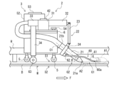
- FIG. 1 is a front view showing a schematic configuration of a processing machine according to a first embodiment of the present disclosure.
- FIG. 2 is a side view of the processing machine shown in FIG.
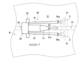
- FIG. 3 is an enlarged plan view showing the vicinity of the torch in the processing machine shown in FIG.
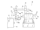
- FIG. 4 is a front view showing a schematic configuration of a processing machine according to a second embodiment of the present disclosure.
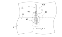
- FIG. 5 is an enlarged plan view showing the vicinity of the processing location in the processing machine shown in FIG.
- FIG. 6 is a diagram showing a schematic configuration of a processing machine in a modification of the second embodiment, as viewed from the direction in which the processing machine body moves relative to the workpiece.
- FIG. 7 is a plan view of the processing machine shown in FIG.
- FIG. 8 is a plan view showing a schematic configuration of a processing machine according to a modified example of the present disclosure.
- the processing machine 1 is a work machine that performs groove processing to form a groove G2 on the back side of the welded portion B of the work W as thermal processing.
- groove processing is called gouging.
- a groove G1 having various shapes such as a V shape, an X shape, a U shape, and a J shape is formed in advance in the work W.
- groove processing is performed on the back side of the work W to form a groove G2 deeper than the original groove G1. This removes defects in the weld bead from the front side, and prevents welding defects from occurring when welding from the back side.
- the thermal processing on the work W in this disclosure is not limited to the thermal processing on the groove G1, but also includes thermal processing on a portion where the groove G1 does not exist.
- the workpiece W to be welded is placed horizontally, and the processing machine 1 is placed on the first surface S1 of the workpiece W. Therefore, in the following explanation, the side farther from the first surface S1 of the workpiece W is the upper side of the processing machine 1, and the side closer to it is the lower side. Furthermore, the first surface S1 of the workpiece W refers to the surface that the processing machine 1 abuts, i.e., the surface facing the torch 21 described below.
- the welded portion B of the workpiece W i.e., the surface on which the weld bead is formed, is the second surface S2 opposite the first surface S1.
- the processing machine 1 includes a processing machine body 2 and a carriage 3.
- the carriage 3 includes a carriage body 4 and wheels 5 supported by the carriage body 4.
- the carriage body 4 includes a fixing surface 6 for fixing the processing machine body 2.
- the carriage body 4 includes a housing 7 having a rectangular parallelepiped shape. The upper surface of the housing 7 forms the fixing surface 6.
- the wheels 5 contact the first surface S1 of the workpiece W.
- the cart 3 is equipped with a motor 8 for moving the cart body 4 on the first surface S1 of the workpiece W.
- the motor 8 is installed inside the housing 7. Power is supplied to the motor 8 from the outside via a power cable 40. Alternatively, a battery may be installed on the cart 3.
- the rail R is fixed to the first surface S1 of the workpiece W along the weld line.
- the method of fixing the rail R is not particularly limited.
- the rail R may be fixed to the workpiece W by welding, by a magnet, or by a vacuum pad.
- the rail R is a rail with a circular cross section.
- the rail R is a pipe rail.
- the cart body 4 includes a rail holder 9 that holds the rail R.
- the housing 7 has a recess 10 on the lower surface, i.e., the surface opposite the fixing surface 6, through which the rail R is inserted.
- the recess 10 has an arc-shaped cross section.
- the rail holder 9 is disposed around the recess 10.
- the rail holder 9 includes a pair of rollers that hold the rail R from both sides.
- the pair of rollers includes a drive roller 11 driven by the motor 8, and a driven roller 12 arranged opposite the drive roller 11.
- the cart body 4 has a link 13 that transmits the driving force of the motor 8 to the drive roller 11 to rotate the drive roller 11.
- the link 13 includes, for example, a gear box. Note that the configuration of the rail holder 9 is not limited to this.
- the rail holder 9 may include an auxiliary roller in addition to the pair of rollers.
- the drive roller 11 rotates by the driving force of the motor 8 while the rail R is clamped between the pair of rollers 11, 12, and the carriage 3 moves along the rail R.
- the carriage 3 moves in the direction of the weld line of the workpiece W relative to the workpiece W.
- the wheels 5 rotate while in contact with the workpiece W. Since the carriage 3 is held on the rail R by the rail holder 9, the carriage 3 can be moved along the rail R and thermal processing can be performed on the workpiece W by the processing machine main body 2 mounted on the carriage 3 not only when the surface of the workpiece W faces upward, but also when it faces sideways or downward.
- the workpiece W may have a curved surface as well as a flat surface.
- a case 52 on which a movement controller 51 is mounted is fixed to a portion of the fixed surface 6 of the trolley body 4.
- the trolley 3 is disposed on the upper surface of the case 52, and has an operation panel 53 for operating the trolley 3.
- the movement controller 51 includes a processing circuit and controls the motor 8.
- the processing machine body 2 is removably fixed to the fixing surface 6.
- the fixing surface 6 has a fixing hole 6a.
- the processing machine body 2 is fixed to the fixing surface 6 by a fixing screw 54 inserted into the fixing hole 6a. By loosening the fixing screw 54, the processing machine body 2 can be removed from the fixing surface 6 of the cart body 4.
- another work machine can be fixed to the fixed surface 6.
- the other work machines may include, for example, a welding machine that performs welding while moving a welding torch, an inspection machine that performs inspection before and after welding or processing, a processing machine that performs processing other than groove processing, etc.
- the processing machine body 2 may be removed from the fixed surface 6, an inspection machine may be fixed to the fixed surface 6, and the carriage 3 may be moved along the rail R to inspect the groove G2 formed by the processing machine 1.
- the processing machine body 2 can be replaced with the inspection machine while the carriage 3 is holding the rail R.
- FIG. 2 is a side view of the processing machine shown in FIG. 1.
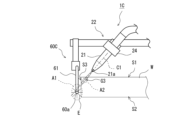
- the processing machine 1 is equipped with a torch 21 that performs thermal processing on the workpiece W.
- the torch 21 is a plasma torch that generates a plasma arc, which serves as a heat source, between the tip 21a of the torch 21 and the processing location A2 of the workpiece W.
- the processing machine body 2 is equipped with a driver 41 for driving the torch 21.
- the driver 41 converts the power supplied from the power source into a predetermined voltage or current and supplies it to the electrode in the torch 21, generating a plasma arc that serves as a heat source between the tip 21a of the torch 21 and the processing point A2 of the workpiece W.
- the power source may be a battery mounted on the processing machine body 2, or power may be supplied to the processing machine body 2 from an external power source via a power cable.
- the power source of the carriage 3 and the power source of the processing machine body 2 may be a common power source.
- the driver 41 is equipped with a processing circuit including an inverter and the like.
- the processing machine body 2 is equipped with an operation panel 42. The driver 41 drives the torch 21 based on the operation of the operation panel 42.
- the processing machine body 2 is equipped with a holder 22 that holds the torch 21 on the carriage 3.
- the torch 21 is positioned at an angle so that the tip 21a is located forward of the base end 21b, based on the movement direction F of the processing machine body 2 relative to the workpiece W during thermal processing.
- the holder 22 maintains the inclined position of the torch 21.
- the inclination angle ⁇ of the central axis C1 of the torch 21 relative to the first surface S1 of the workpiece W is not particularly limited, but is, for example, 30 degrees.
- the processing machine body 2 includes a first body 31 fixed to the fixed surface 6, and a second body 32 extending forward from the first body 31.
- the second body 32 is configured to be movable in the width direction relative to the first body 31.
- the holder 22 includes an arm 23 supported by the second body 32, and a clamp 24 supported by the arm 23 and holding the torch 21.
- the holder 22 is configured to be able to change the inclination angle ⁇ and the torch height of the torch 21.
- the torch height is defined as the height of the tip 21a of the torch 21 relative to the first surface S1 of the workpiece W.
- the processing machine 1 in this embodiment performs thermal processing to form a groove G2 on the first surface S1 of the workpiece W by generating a plasma arc between the tip 21a of the torch 21 and the processing point A2 of the workpiece W while moving the processing machine body 2 to which the torch 21 is fixed relative to the workpiece W.
- the processing machine 1 is equipped with an ejector 60 that ejects the ejection body E.
- the ejector 60 ejects the ejection body E toward the first surface S1 of the workpiece W facing the torch 21.
- the ejector 60 is directed toward a predetermined area A1 on the first surface S1 of the workpiece W that is determined based on the processing location A2 of the workpiece W.
- the ejection port 60a of the ejector 60 is located on the first surface S1 side of the workpiece W and forward of the tip 21a of the torch 21 based on the moving direction F.
- the ejector 60 is positioned so that the ejection port 60a at the tip is positioned forward of the base end.
- the ejector 60 ejects the ejection body E forward in the moving direction F. Furthermore, the ejection port 60a is positioned at a position where the distance from the first surface S1 of the workpiece W is less than a predetermined distance. Furthermore, the nozzle 60a is positioned so that the ejection direction of the ejection body E is horizontal or at an angle close to horizontal with respect to the first surface S1 of the workpiece W.
- the ejector 60 is fixed to the processing machine body 2.
- the ejector 60 is held by the holder 22.
- the ejector 60 has a pair of left and right nozzles 61 arranged on both the left and right sides of the torch 21.
- the pair of nozzles 61 are arranged so that the distance between them is wider than the groove width or the groove G2 formed by the torch 21.
- the nozzles 61 are connected to a supply pipe 62 that supplies the ejection body.
- the supply pipe 62 is fixed to the clamp 24 of the holder 22.
- the holder that holds the torch 21 and the holder that holds the ejector 60 are common or integrated. Therefore, even if the position of the torch 21 is adjusted, for example, by moving the second body 32 in the width direction relative to the first body 31, the positional relationship between the torch 21 and the ejector 60 can be maintained. Note that the holder that holds the torch 21 and the holder that holds the ejector 60 may be configured independently of each other.
- the nozzle 60a of the ejector 60 has a shape that is long in the direction parallel to the surface of the workpiece W, i.e., in the width direction of the groove.
- the nozzle 60a has an oval or elliptical shape that is long in the left-right direction.
- the nozzle 61 may be formed from a circular pipe, and the tip of the nozzle 61 may be formed as the nozzle 60a by pressing the tip in the vertical direction.
- the nozzle 60a having an oval or elliptical shape that is long in the width direction of the groove may be attached to the tip of the nozzle 61 formed from a circular pipe.
- the ejection body E ejected from the ejector 60 is, for example, a specified gas.
- the specified gas includes, for example, an inert gas such as argon or nitrogen. By using an inert gas, it is possible to prevent the workpiece W from oxidizing when the ejection body E is sprayed onto the workpiece W.
- the specified gas is not limited to an inert gas, and may be other gases such as oxygen or air, in order to achieve the purpose of removing dross.
- the ejection body E is not limited to a gas, and may be a liquid or solid.
- the ejection body E may be water, an abrasive such as sand, or dry ice.
- the processing machine 1 is equipped with a copy roller 63.
- the copy roller 63 is supported by the processing machine body 2.
- the processing machine body 2 includes a third body 33 extending rearward from the first body 31, and a fourth body 34 extending downward from the third body 33.
- the copy roller 63 is supported by the lower end of the fourth body 34.
- the copy roller 63 is arranged so that its widthwise center position coincides with the widthwise center position of the torch 21.
- the copy roller 63 makes the processing machine body 2 copy the groove G2 formed behind the torch 21 with reference to the moving direction F.
- the height of the copy roller 63 is set to a height such that it is located within the groove G2 of the workpiece W. In other words, the lowest end of the copy roller 63 is located at a position lower than the lowest end of the wheel 5.
- the processing machine 1 By equipping the processing machine 1 with the tracing roller 63, the processing machine 1 can be reliably traced to the groove G2 that has actually been formed. This allows the processing machine 1 to be moved more stably over the workpiece W. This can further promote the automation of groove processing.
- FIG. 3 is an enlarged plan view showing the vicinity of the torch in the processing machine shown in FIG. 1.
- configurations other than the torch 21, clamp 24, and ejector 60 in the processing machine 1 are omitted.
- the torch 21 is positioned at an angle so that the tip 21a is located forward of the base end 21b, and therefore, as shown in FIG. 3, the processing location A2 of the workpiece W is located forward of the tip 21a of the torch 21.
- a plasma arc is formed between the groove position of the workpiece W forward of the tip 21a of the torch 21 and the tip 21a of the torch 21.
- the processing machine 1 including the torch 21 moves in the moving direction F relative to the workpiece W.
- a part of the workpiece W at the processing location A2 is melted by the plasma arc and becomes dross.
- the dross is blown forward by the plasma arc.
- the blown dross accumulates or is about to accumulate in front of the processing location A2 and on both sides of the groove of the first surface S1 of the workpiece W.
- the area where the dross accumulates or is about to accumulate is set as the predetermined area A1.
- the predetermined area A1 is set to an area including the edge of the groove G1, that is, the edge of the groove G2 after formation.
- the ejector 60 ejects the ejection body E toward the predetermined area A1 thus set.
- the ejection body E is ejected from the front of the tip 21a of the torch 21 in the moving direction forward, based on the first surface S1 side of the workpiece W and the moving direction F of the torch 21 relative to the workpiece W.
- any dross that has come near the specified area A1 is blown forward. Even if dross accumulates in the specified area A1, it is blown away by the ejection body E before it cools and adheres to the workpiece W at that position. In this way, by ejecting the ejection body E toward the first surface S1 of the workpiece W while performing thermal processing on the processing location A2 of the workpiece W, it is possible to prevent dross from accumulating on the first surface S1 of the workpiece W during groove processing.
- Dross is prevented from accumulating on the first surface S1 of the workpiece W during groove machining, which can stabilize the quality of the groove machining and promote automation of the groove machining. If dross accumulates on the first surface S1 of the workpiece W, particularly on the edge of the groove G1, during groove machining, the torch 21 may come into contact with the dross, which may damage the torch 21 or cause poor generation of the plasma arc. In addition, the plasma arc that should be generated between the tip 21a of the torch 21 and the processing point A2 of the workpiece W may be generated between the tip 21a of the torch 21 and the dross. This is generally referred to as a double arc. If a double arc occurs, the plasma arc between the tip 21a of the torch 21 and the processing point A2 of the workpiece W may be weakened or cut off. As a result, defects may occur in the groove machining.
- the above-mentioned problems associated with the accumulation of dross on the first surface S1 of the workpiece W can be resolved. Therefore, the quality of the groove machining performed by the processing machine 1 can be stabilized. In addition, the automation of groove machining by the processing machine 1 can be promoted.
- the nozzle 60a of the ejector 60 is located on the first surface S1 side of the workpiece W and forward of the tip 21a of the torch 21 with respect to the moving direction F, and the ejector 60 is configured to eject the ejection body E forward in the moving direction F.
- the ejection port 60a of the ejector 60 has a long shape in a direction parallel to the surface of the workpiece W. This makes it possible to increase the ejection speed of the ejection body E ejected from the ejection port 60a. In addition, the ejection body E can be ejected over a wide range in the width direction.
- the ejection port 60a is located before the specified area A1 with respect to the moving direction F. This prevents interference between the nozzle 61 of the ejector 60 and the dross.
- the ejector 60 is equipped with a pair of nozzles 61 arranged on the left and right sides of the torch 21. This allows the ejection body E to efficiently blow away the dross that has accumulated on the left and right sides of the groove G2 on the first surface S1.
- the ejector 60 includes a pair of nozzles 61 on the left and right, but the configuration of the ejector 60 is not limited to the above-mentioned aspect as long as the ejection body E can be ejected toward a predetermined area A1 that is determined based on the processing location A2 of the workpiece W.
- the configuration of the ejector 60 is not limited to the above-mentioned aspect as long as the ejection body E can be ejected toward a predetermined area A1 that is determined based on the processing location A2 of the workpiece W.
- one nozzle 61 is arranged on each of the left and right sides, but instead of this, two or more nozzles may be arranged on each side.
- the nozzles may be arranged in parallel in the width direction or in parallel in the height direction.
- one or more nozzles may be arranged above the torch 21.
- the nozzle 60a is located forward of the tip 21a of the torch 21 with respect to the direction of movement F, and may be configured to eject the ejection body E forward in the direction of movement F.
- a plurality of nozzles may be arranged in an arc shape above the torch 21 on a concentric circle of the torch 21.
- a nozzle formed in an arc shape may be arranged above the torch 21.
- each nozzle 60a may be arranged facing diagonally forward in the moving direction F.
- the direction in which each nozzle 60a faces may be a direction obtained by adding a widthwise or heightwise component to the forward component of the moving direction F.
- the two or more nozzles may extend radially, or the two or more nozzles may be oriented radially.
- the processing machine 1 is illustrated as having a configuration with a tracing roller 63, but the tracing roller 63 does not have to be provided. Also, the processing machine body 2 may not be detachable from the carriage 3. In other words, the configuration for dross removal in the above embodiment 1 may be adopted even in a processing machine 1 dedicated to groove processing.
- the carriage 3 is controlled by the movement controller 51 and the torch 21 is driven by the driver 41, but this is not limiting.
- the movement controller 51 and the driver 41 may be connected so as to be able to communicate with each other.
- the driver 41 may control the driving of the torch 21 based on a command signal sent from the movement controller 51.
- the driving of the torch 21 may be switched on or off based on the traveling position of the carriage 3.
- the operation panel 53 of the cart 3 is provided on the cart 3, and the operation panel 42 of the processing machine main body 2 is provided on the processing machine main body 2, but this is not limited to this.
- the cart 3 or the processing machine main body 2 may be provided with a common operation panel for operating the cart 3 and the torch 21.
- a remote control terminal for remotely controlling the cart 3 or the processing machine main body 2, or the cart 3 or the processing machine main body 2 may be provided separately from the main body of the processing machine 1.
- the remote control terminal is connected to the main body of the processing machine 1 by wire or wirelessly. If connected wirelessly, the remote control terminal may be a communication terminal such as a smartphone that can communicate via a network such as the Internet.
- FIG. 4 is a front view showing the schematic configuration of a processing machine according to embodiment 2 of the present disclosure.
- Processing machine 1B in this embodiment is a work machine that performs thermal processing such as drilling or cutting on a workpiece W. Generally, drilling is called piercing.
- the processing machine 1B has a processing machine body 2B configured as a carriage. That is, the processing machine body 2B has a carriage body 4 and wheels 5 supported by the carriage body 4. The housing of the processing machine body 2B is common to the carriage body 4. The wheels 5 are installed on a specified rail R.
- the processing machine 1B is equipped with a torch 21 that performs thermal processing on the workpiece W.
- the torch 21 is a plasma torch that generates a plasma arc that serves as a heat source between the tip 21a of the torch 21 and the processing location A2 of the workpiece W.
- the processing machine body 2 is equipped with a holder 22 that holds the torch 21 to the processing machine body 2.
- the torch 21 is arranged perpendicular to the first surface S1 of the workpiece W placed on the workpiece placement table 70 so that the tip 21a faces the first surface S1.
- the torch 21 is arranged so that a virtual straight line extending from the tip 21a of the torch 21 toward the processing location A2 of the workpiece W intersects with the first surface S1 of the workpiece and the second surface S2 opposite to the first surface S1.
- the virtual straight line can be said to be an extension of the central axis C1 of the torch 21.
- the virtual straight line is perpendicular to the first surface S1 and the second surface S2.
- the holder 22 includes a first body 25, a second body 26, and a clamp 24.
- the first body 25 is supported by the carriage body 4 and extends in the vertical direction.
- the second body 26 is supported by the first body 25 and extends in a direction perpendicular to the moving direction F, i.e., in the width direction of the rail R.
- the clamp 24 is supported by the second body 26 and holds the torch 21.
- the second body 26 may be movable in the up-down direction relative to the first body 25.
- the clamp 24 may be movable in the width direction of the rail R relative to the second body 26. This allows the position of the tip of the clamp 24 to be adjusted.
- the carriage body 4 is equipped with a motor 8 for moving the carriage body 4 on the rail R.
- the motor 8 is installed inside the carriage body 4. Power is supplied to the motor 8 from the outside via a power cable 40. Alternatively, a battery may be mounted on the carriage body 4.
- the wheels 5 are rotated by the power output from the motor 8, and the processing machine body 2B moves in a direction along the rail R.
- the processing machine body 2B is provided with a movement controller 51 for controlling the motor 8 and a driver 41 for driving the torch 21 within the carriage body 4.
- the movement controller 51 and the driver 41 may be configured as a single processing circuit.
- An operation panel 52B for operating the processing machine 1B is disposed on the top surface of the carriage body 4. Based on operation input to the operation panel 52B, the movement controller 51 controls the movement of the processing machine body 2B, and the driver 41 controls the drive of the torch 21.
- the processing machine 1B performs thermal processing to drill a hole in the workpiece W by generating a plasma arc between the tip 21a of the torch 21 and the processing location A2 of the workpiece W while the processing machine body 2 is stopped.
- the processing machine 1B also performs thermal processing to cut the workpiece W by generating a plasma arc between the tip 21a of the torch 21 and the processing location A2 of the workpiece W while moving the processing machine body 2 relative to the workpiece W.
- the cutting processing is performed by moving the processing machine body 2 from that position after the hole drilling processing is performed while the processing machine body 2 is stopped.
- the processing machine 1B also includes an ejector 60B.
- the ejector 60B is supported by the processing machine body 2.
- the ejector 60B includes a nozzle 61 and a holder 64 that holds the nozzle 61.
- the holder 64 is fixed to the carriage body 4.
- the ejector outlet 60a of the ejector 60B is positioned so as to eject the ejection body E on the second surface S2 side of the workpiece W.
- the ejector outlet 60a is also positioned at a position where the distance to the second surface S2 of the workpiece W is equal to or less than a predetermined distance.
- the ejector outlet 60a is positioned so that the ejection direction of the ejection body E is horizontal or at an angle close to horizontal with respect to the second surface S2 of the workpiece W.
- FIG. 5 is an enlarged plan view showing the vicinity of the machining location in the processing machine shown in FIG. 4.
- FIG. 5 is a view of the vicinity of the machining location A2 as seen from the second surface S2 side of the workpiece W.
- configurations other than the torch 21 and the nozzle 61 of the ejector 60B in the processing machine 1B are omitted.
- the torch 21 is disposed perpendicular to the first surface S1 of the workpiece W, so that the machining location A2 of the workpiece W is an area that spreads concentrically around the tip 21a of the torch 21 in a plan view, as shown in FIG. 5.
- a plasma arc is formed between the workpiece W directly below the tip 21a of the torch 21 and the tip 21a of the torch 21.
- the plasma arc melts the workpiece W at the processing location A2, turning it into dross.
- the plasma arc penetrates the workpiece W at the processing location A2, and the resulting dross accumulates or attempts to accumulate around the processing location A2 on the second surface S2 of the workpiece W.
- the processing machine 1B including the torch 21 moves in the movement direction F relative to the workpiece W.
- the processing location A2 moves in the movement direction F in conjunction with the movement of the torch 21, and a notch G3 is formed in the portion of the workpiece W that the processing location A2 passes through.
- the resulting dross accumulates or attempts to accumulate on one or both sides of the notch G3 on the second surface S2 of the workpiece W.
- the area where the dross accumulates or attempts to accumulate is set as the predetermined area A1.
- the predetermined area A1 is set to an area that includes one or both sides of the edge of the notch G3 formed at the processing location A2.
- the predetermined area A1 is set around the processing location A2.
- the ejector 60B ejects the ejection body E toward the predetermined area A1 thus set.
- the ejection port 60a of the ejector 60B is positioned so that an imaginary straight line extending from the tip 21a of the torch 21 toward the processing location A2 of the workpiece W, i.e., an extension of the central axis C1 of the torch 21, intersects with the ejection direction of the ejection body E, i.e., an extension of the central axis of the ejection port 60a.
- an imaginary straight line extending from the tip 21a of the torch 21 toward the processing location A2 of the workpiece W i.e., an extension of the central axis C1 of the torch 21
- the ejection direction of the ejection body E i.e., an extension of the central axis of the ejection port 60a.
- the ejection port 60a of the ejector 60B is positioned so that the movement direction F of the processing machine body 2 relative to the workpiece W during cutting and the ejection direction of the ejection body E intersect when viewed from a direction perpendicular to the first surface S1 or the second surface S2.
- the movement direction F and the ejection direction of the ejection body E are perpendicular to each other.
- dross generated near the specified area A1 is blown off to the side. Even if dross accumulates in the specified area A1, it is blown off by the ejection body E before it cools and adheres to the workpiece W at that position. In this way, by ejecting the ejection body E toward the second surface S2 of the workpiece W while performing thermal processing on the processing location A2 of the workpiece W, it is possible to prevent dross from accumulating on the second surface S2 of the workpiece W during drilling or cutting.
- the nozzle 60a of the ejector 60B is positioned so that the direction of movement F of the machine body 2 relative to the workpiece W during cutting intersects with the ejection direction of the ejected body E. Therefore, even if dross accumulates on both sides of the edge of the notch G3, and even if the ejection range of the ejected body E is narrow horizontally, the dross on both sides can be efficiently blown away at once.
- the ejected body E or the blown away dross may intersect with the plasma arc on the second surface S2 side of the workpiece W. However, this does not cause a problem because the portion of the plasma arc on the second surface S2 side of the workpiece W does not affect the cutting or drilling of the workpiece W.
- the ejection port 60a of the ejector 60B is arranged so that the moving direction F of the processing machine body 2 relative to the workpiece W during cutting and the ejection direction of the ejection body E intersect, but this is not limited to the above.
- the ejection port 60a of the ejector 60B may be arranged so as to eject the ejection body E in a direction along the moving direction F, as in the above-mentioned first embodiment.
- the ejector 60B may be provided with a plurality of ejection ports 60a, or the ejection port 60a may be made wide, etc., so that the dross accumulated on both sides of the edge of the notch G3 can be blown off more efficiently.
- the ejector 60B has one nozzle 61, but the number of nozzles 61 may be two or more.
- the arrangement of the nozzle 61 and the ejection port 60a is not particularly limited as long as the ejection body E can be ejected toward the above-mentioned specified area A1.
- the processing machine body 2B functions as a cart
- the cart and the processing machine body 2B may be configured separately, and the processing machine body 2B may be detachable from the cart.
- the processing machine body 2B moves on the rail R by the driving force of the wheels 5, but as in embodiment 1, the processing machine body 2B may be configured to move along the rail R by the driving force of the driving side rollers 11 that constitute the rail holder 9 that holds the rail R.
- the ejection port 60a of the ejector 60B is arranged on the second surface S2 side opposite the first surface S1 of the workpiece W facing the torch 21, but as long as the ejector 60B is arranged on a surface other than the first surface S1 of the workpiece W that intersects with an imaginary straight line extending from the tip 21a of the torch 21 toward the workpiece W, a configuration similar to that of the above-mentioned second embodiment can be applied.
- FIG. 6 is a diagram showing the schematic configuration of a processing machine in a modified example of embodiment 2, viewed from the direction in which the processing machine body moves relative to the workpiece.
- FIG. 7 is a plan view of the processing machine shown in FIG. 6.
- the same components as those in embodiment 2 are given the same reference numerals, and their explanations are omitted.
- the processing machine body 2B is not shown in FIGS. 6 and 7, it can have the same configuration as embodiment 2, for example.
- the torch 21 is positioned so as to cut the end of the workpiece W at an angle in order to form a groove at the end of the workpiece W. For this reason, the torch 21 is held in the holder 22 so as to be inclined with respect to the first surface S1 of the workpiece W in a direction intersecting the movement direction F of the processing machine body 2B relative to the workpiece W. In other words, the torch 21 is positioned so that the above-mentioned imaginary straight line, which is an extension of the central axis C1, intersects with the first surface S1 of the workpiece W and the side surface S3 that intersects with the first surface S1.
- the ejector 60C is also held by the holder 22.
- the ejector outlet 60a of the ejector 60C is located on the side surface S3 side. Furthermore, in this modified example, the ejector outlet 60a of the ejector 60C is located rearward of the tip 21a of the torch 21 with respect to the moving direction F, and the ejector 60C is configured to eject the ejection body E forward in the moving direction F.
- a plasma arc is also formed between the workpiece W on the extension of the central axis C1 of the torch 21 and the tip 21a of the torch 21.
- the plasma arc that is formed melts the workpiece W at the processing point A2 and turns it into dross.
- the plasma arc penetrates the workpiece W at the processing point A2, so the resulting dross accumulates or attempts to accumulate around or below the processing point A2 on the side surface S3 of the workpiece W.
- the predetermined area A1 is set to an area including the lower side of the edge of the notch G3 formed at the processing point A2.
- the ejector 60C ejects the ejected body E toward the predetermined area A1 thus set.
- the ejection port 60a of the ejector 60B is positioned so that its central axis is located below an imaginary straight line extending from the tip 21a of the torch 21 toward the processing point A2 of the workpiece W, i.e., below the extension of the central axis C1 of the torch 21.
- the specified area A1 may be set to an area including both the upper and lower sides of the edge of the notch G3 formed at the processing point A2.
- the ejection port 60a of the ejector 60B may be positioned so that its central axis intersects with an imaginary straight line extending from the tip 21a of the torch 21 toward the processing point A2 of the workpiece W.
- dross generated near the specified area A1 is blown off to the side. Even if dross accumulates in the specified area A1, it is blown off by the ejection body E before it cools and adheres to the workpiece W at that position. In this way, by ejecting the ejection body E toward the side surface S3 of the workpiece W while performing thermal processing on the processing location A2 of the workpiece W, it is possible to prevent dross from accumulating on the side surface S3 of the workpiece W during drilling or cutting.
- the ejection direction of the ejector 60C is aligned with the movement direction F of the processing machine body 2B, but the ejection direction of the ejector 60C may be vertical.
- the ejection direction of the ejector 60C may also be an oblique direction that includes a component along the movement direction and a vertical component.
- plasma processing in which a plasma arc is generated between the tip 21a of the torch 21 and the processing location A2 of the workpiece W is exemplified as thermal processing, but it is possible to employ various processing methods in which a heat source is generated between the tip 21a of the torch 21 and the processing location A2 of the workpiece W and processing can be performed using the heat source.
- the contents of this disclosure are applicable to processing machines that employ processing methods that generate dross during processing.
- this disclosure can also be applied to processing machines that perform thermal processing by irradiating gas, laser, electron beam, etc. from the torch 21, and similar effects can be achieved.
- the ejectors 60, 60B are held by the processing machine main body 2, 2B, but the ejectors 60, 60B may be configured separately from the processing machine main body 2, 2B.
- the position of the ejectors 60, 60B themselves or the position of the ejection port 60a moves so as to maintain the positional relationship between the ejection port 60a and the specified area A1 in accordance with the movement of the processing machine main body 2, 2B.
- the ejectors 60, 60B and the processing machine main body 2, 2B may be controlled in a coordinated manner.
- the processing machine body 2, 2B moves along the rail R relative to the workpiece W, but this is not limited to the above.
- the processing machine body 2, 2B may be connected to a base and configured as a robot equipped with an arm having multiple joints.
- a holder 22 is fixed to the tip of the arm, and a robot controller that controls the robot may control the position of the torch 21 fixed to the holder 22 by operating the arm.
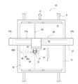
- FIG 8 is a plan view showing the schematic configuration of a processing machine in a modified example of the present disclosure.
- the processing machine 1D in this modified example is a work machine that performs thermal processing such as drilling or cutting the workpiece W, similar to embodiment 2.
- the work W is placed on a work cart 71.
- the work cart 71 is configured to be movable on rails R. Note that instead of a moving mechanism that can move on rails R, the work cart 71 can employ various moving mechanisms that can move in the moving direction Q.
- the processing machine body 2D is fixed to a fixed object such as the ground.
- the processing machine body 2D is equipped with a first support 27 fixed to the fixed object, a second support 28 supported by the first support 27, and a clamp 24 supported by the second support 28.
- the first support 27 includes an extension body 27a extending in a direction perpendicular to the movement direction Q of the work carriage 71, and legs 27b fixed to a fixed object at both ends of the extension body 27a.
- the extension body 27a has a length longer than the width of the work carriage 71.
- the work carriage 71 is positioned between the two legs 27b so that it can pass through.
- the second support 28 is configured to be movable on the extension 27a of the first support 27 in a direction perpendicular to the movement direction Q.
- the clamp 24 holds the torch 21.
- the clamp 24 is configured to be movable in the height direction relative to the second support 28.
- the workpiece W is transported in the movement direction Q by the workpiece carriage 71 to the processing machine body 2D fixed to a fixed object, so that the torch 21 held by the processing machine body 2C moves relative to the workpiece W in the movement direction F.
- the ejector 60D is fixed to a fixed object such as the ground.
- the ejector 60D includes a base 65 fixed to the fixed object, a holder 64 supported by the base 65, and a nozzle 61 held by the holder 64.
- the positional relationship of the ejector 60C nozzle 60a with the torch 21 and the ejection direction of the ejection body E are the same as in the second embodiment.
- the dross can be removed by ejecting the ejection body E toward a predetermined area A1 that is determined based on the processing location A2 of the workpiece W on the second surface S2 of the workpiece W facing the torch 21, thereby preventing the accumulation of dross on the workpiece W.
- the ejector may be held in the processing machine body or separately from the processing machine body.
- the ejector may be suspended from above the building in which the processing machine is installed.
- a processing machine for performing thermal processing on a workpiece, and comprises a processing machine body configured to be movable relative to the workpiece, a torch fixed to the processing machine body and generating a heat source between its tip and a processing location of the workpiece, and an ejector that ejects an ejection body toward a first surface of the workpiece facing the torch to remove dross that accumulates in the specified area as a result of the thermal processing, the torch is positioned at an angle so that its tip is located forward of its base end based on the movement direction of the processing machine body relative to the workpiece during the thermal processing, and the ejector's nozzle is located on the side of the first surface of the workpiece and forward of the tip of the torch based on the movement direction, the ejector ejects the ejection body forward in the movement direction, and the processing machine forms a groove on the first surface of the workpiece by performing the
- the ejection body is ejected from the ejector toward a predetermined area, and during thermal processing that generates dross on the first surface side of the workpiece, any dross that flies near the predetermined area is blown away. Even if dross accumulates in the predetermined area, it is blown away by the ejection body before it cools and adheres to the workpiece at that position. In this way, by ejecting the ejection body toward the first surface of the workpiece while performing thermal processing on the processing location of the workpiece, it is possible to prevent dross from accumulating on the first surface of the workpiece W during groove processing.
- the nozzle As described above and ejecting the ejection body forward in the direction of movement from that position, it is possible to prevent the nozzle of the ejector itself, the ejection body ejected from the nozzle, and the dross blown away by the ejection body from interfering with the plasma arc. Therefore, the dross can be removed without affecting the thermal processing.
- the ejector may include a pair of nozzles arranged on the left and right sides of the torch. This makes it possible to efficiently blow away the dross with the ejection body.
- the processing machine of item 1 may include a profiling roller that is supported by the processing machine body and causes the processing machine body to profiling a groove formed behind the torch with respect to the moving direction. This allows the processing machine to reliably profiling the groove formed by thermal processing. This allows the processing machine to be moved more stably above the workpiece. Therefore, automation of groove processing can be further promoted.
- a processing machine for performing thermal processing on a workpiece, and includes a processing machine body, a torch fixed to the processing machine body and generating a heat source between its tip and a processing location of the workpiece, and an ejector that ejects an ejection body toward a predetermined area determined based on the processing location of the workpiece on a surface other than a first surface of the workpiece facing the torch and intersects with a virtual straight line extending from the tip of the torch toward the processing location of the workpiece, for removing dross that accumulates in the predetermined area as a result of the thermal processing.
- the ejection body is ejected from the ejector toward a predetermined area, and in thermal processing in which dross is generated on a surface side other than the first surface of the workpiece, any dross that has come close to the predetermined area is blown away. Even if dross accumulates in the predetermined area, it is blown away by the ejection body before it cools and adheres to the workpiece at that position. In this way, by ejecting the ejection body toward a surface other than the first surface of the workpiece while performing thermal processing on the processing location of the workpiece, it is possible to prevent dross from accumulating on a surface other than the first surface of the workpiece W during groove processing.
- the ejection port of the ejector may be disposed on a surface side different from the first surface of the workpiece and such that a virtual straight line extending from the tip of the torch toward the processing location of the workpiece intersects with the ejection direction of the ejection body. This allows the dross on both sides of the cut groove or around the cut hole to be blown off at once on the surface side different from the first surface of the workpiece. Therefore, the dross can be efficiently removed.
- the processing machine body may be configured to be movable relative to the workpiece, and the ejection port of the ejector may be disposed so that the moving direction of the processing machine body relative to the workpiece during the thermal processing intersects with the ejection direction of the ejection body. This makes it possible to efficiently blow away dross generated on the second surface side of the workpiece.
- the torch may be positioned so that the imaginary straight line intersects with the first surface of the workpiece and a second surface opposite to the first surface, and the nozzle of the ejector may be directed toward the second surface.
- the torch may be disposed so that the imaginary straight line intersects with the first surface of the workpiece and a side surface that intersects with the first surface, and an ejection nozzle of the ejector may be directed toward the side surface.
- the ejector may have an ejection port that is elongated in a direction parallel to the surface of the workpiece. This makes it possible to increase the ejection speed of the ejected material ejected from the ejection port. Also, the ejected material can be ejected over a wide range in the width direction.
- a processing method for performing thermal processing on a workpiece, comprising: holding a torch that generates a heat source between its tip and the processing location of the workpiece, toward the processing location of the workpiece, and performing the thermal processing on the processing location of the workpiece by generating the heat source; ejecting an ejection body toward a first surface of the workpiece facing the torch to remove dross that accumulates in the specified area as a result of the thermal processing, and performing the thermal processing while moving the torch relative to the workpiece to form a groove on the first surface of the workpiece; and ejecting the ejection body from forward of the tip of the torch in the direction of movement, based on the first surface side of the workpiece and the direction of movement of the torch relative to the workpiece.
- a processing method for performing thermal processing on a workpiece, comprising: holding a torch that generates a heat source between its tip and the processing point of the workpiece, toward the processing point of the workpiece; and performing the thermal processing on the processing point of the workpiece by generating the heat source, while ejecting an ejection body toward a predetermined area determined based on the processing point of the workpiece on a surface other than a first surface of the workpiece facing the torch, and on a surface that intersects with a virtual straight line extending from the tip of the torch toward the processing point of the workpiece, for removing dross that accumulates in the predetermined area as a result of the thermal processing.
Landscapes
- Engineering & Computer Science (AREA)
- Mechanical Engineering (AREA)
- Physics & Mathematics (AREA)
- Plasma & Fusion (AREA)
- Optics & Photonics (AREA)
- Arc Welding In General (AREA)
- Laser Beam Processing (AREA)
- Cleaning By Liquid Or Steam (AREA)
Abstract
Description
以下、本開示の実施の形態1に係る加工機について説明する。
上記実施の形態1では、噴出器60が左右一対のノズル61を備える例を示したが、ワークWの加工箇所A2に基づいて定められる所定の領域A1に向けて噴出体Eを噴出させることができれば、噴出器60の構成は、上記態様に限られない。例えば、上記実施の形態1では、左右に1つずつのノズル61が配置される例を示したが、これに代えて、片側あたり2以上のノズルが配置されてもよい。ノズルの配置態様は、幅方向に並列配置されてもよいし、高さ方向に並列配置されてもよい。
次に、本開示の実施の形態2に係る加工機について説明する。
上記実施の形態2においては、噴出器60Bの噴出口60aは、切断加工時における加工機本体2のワークWに対する移動方向Fと噴出体Eの噴出方向とが交差するように配置される態様を例示したがこれに限られない。例えば、噴出器60Bの噴出口60aは、上記実施の形態1のように、移動方向Fに沿った方向に噴出体Eを噴出するように配置されてもよい。なお、噴出器60Bの噴出口60aが移動方向Fと噴出体Eの噴出方向とが交差しない場合であっても、切れ込みG3の縁部の両側に堆積したドロスを吹き飛ばすことが可能である。この場合、噴出器60Bが複数の噴出口60aを備える、または、噴出口60aを幅広形状とすること等により、より効率的に切れ込みG3の縁部の両側に堆積したドロスを吹き飛ばすことができる。
以上、本開示の実施の形態について説明したが、本開示は上記実施の形態に限定されるものではなく、その趣旨を逸脱しない範囲内で種々の改良、変更、修正が可能である。
[項目1]
本開示の一態様に係る加工機は、ワークに対して熱加工を行うための加工機であって、前記ワークに対して相対移動可能に構成される加工機本体と、前記加工機本体に固定され、先端と前記ワークの加工箇所との間に熱源を発生させるトーチと、前記トーチに対向する前記ワークの第1面に向けて、前記熱加工に伴って前記所定の領域に堆積するドロスを除去するための噴出体を噴出する噴出器と、を備え、前記トーチは、前記熱加工時における前記加工機本体の前記ワークに対する移動方向を基準として先端が基端に対して前方に位置するように傾斜して配置され、前記噴出器の噴出口は、前記ワークの第1面側かつ前記移動方向を基準として前記トーチの先端より前方に位置し、前記噴出器は、前記移動方向前方に前記噴出体を噴出し、前記加工機は、加工機本体を移動させながら前記熱加工を行うことにより前記ワークの前記第1面に溝を形成する。
項目1の加工機において、前記噴出器は、前記トーチの左右両側に配置された左右一対のノズルを備えてもよい。これにより、噴出体によりドロスを効率的に吹き飛ばすことができる。
項目1の加工機は、前記加工機本体に支持され、前記移動方向を基準として前記トーチより後方において形成された溝に前記加工機本体を倣わせる倣いローラを備えてもよい。これにより、加工機を熱加工により形成された溝に確実に倣わせることができる。これにより、加工機をワーク上においてより安定的に移動させることができる。したがって、溝加工の自動化をより促進することができる。
本開示の他の態様に係る加工機は、ワークに対して熱加工を行うための加工機であって、加工機本体と、前記加工機本体に固定され、先端と前記ワークの加工箇所との間に熱源を発生させるトーチと、前記トーチに対向する前記ワークの第1面とは異なる面であって、前記トーチの先端から前記ワークの加工箇所に向けて延びる仮想の直線と交差する面において前記ワークの加工箇所に基づいて定められる所定の領域に向けて、前記熱加工に伴って前記所定の領域に堆積するドロスを除去するための噴出体を噴出する噴出器と、を備えている。
項目4の加工機において、前記噴出器の噴出口は、前記ワークの前記第1面とは異なる面側かつ前記トーチの先端から前記ワークの加工箇所に向けて延びる仮想の直線と前記噴出体の噴出方向とが交差するように配置されてもよい。これによれば、ワークの第1面とは異なる面側において切削溝の両側または切削穴の周囲のドロスを一度に吹き飛ばすことができる。したがって、効率的なドロスの除去を行うことができる。
項目4または5の加工機において、前記加工機本体は前記ワークに対して相対移動可能に構成され、前記噴出器の噴出口は、前記熱加工時における前記加工機本体の前記ワークに対する移動方向と前記噴出体の噴出方向とが交差するように配置されてもよい。これによれば、ワークの第2面側に発生するドロスを効率的に吹き飛ばすことができる。
項目4から6の何れかの加工機において、前記トーチは、前記仮想の直線が前記ワークの前記第1面および前記第1面とは反対側の第2面に交差するように配置され、前記噴出器の噴出口は、前記第2面に向けられてもよい。
項目4から7の何れかの加工機において、前記トーチは、前記仮想の直線が前記ワークの前記第1面および前記第1面と交差する側面に交差するように配置され、前記噴出器の噴出口は、前記側面に向けられてもよい。
項目1から8の何れかの加工機において、前記噴出器の噴出口は、前記ワークの表面に平行な方向に長い形状を有していてもよい。これにより、噴出口から噴出する噴出体の噴出速度を高くすることができる。また、噴出体を幅方向に広い範囲に噴出させることができる。
本開示の他の態様に係る加工方法は、ワークに対して熱加工を行うための加工方法であって、先端と前記ワークの加工箇所との間に熱源を発生させるトーチを、前記ワークの加工箇所に向けて保持し、前記熱源を発生させることにより前記ワークの加工箇所に対して前記熱加工を行いながら、前記トーチに対向する前記ワークの第1面に向けて、前記熱加工に伴って前記所定の領域に堆積するドロスを除去するための噴出体を噴出させ、前記トーチを前記ワークに対して移動させながら前記熱加工を行うことにより前記ワークの前記第1面に溝を形成し、前記ワークの第1面側かつ前記トーチの前記ワークに対する移動方向を基準として前記トーチの先端より前方から前記移動方向前方に前記噴出体を噴出させる。
本開示の他の態様に係る加工方法は、ワークに対して熱加工を行うための加工方法であって、先端と前記ワークの加工箇所との間に熱源を発生させるトーチを、前記ワークの加工箇所に向けて保持し、前記熱源を発生させることにより前記ワークの加工箇所に対して前記熱加工を行いながら、前記トーチに対向する前記ワークの第1面とは異なる面であって、前記トーチの先端から前記ワークの加工箇所に向けて延びる仮想の直線と交差する面において前記ワークの加工箇所に基づいて定められる所定の領域に向けて、前記熱加工に伴って前記所定の領域に堆積するドロスを除去するための噴出体を噴出させる。
2,2B,2D 加工機本体
21 トーチ
60,60B,60C,60D 噴出器
60a 噴出口
61 ノズル
63 倣いローラ
A1 所定の領域
A2 加工箇所
E 噴出体
F 移動方向
G2 溝
S1 第1面
S2 第2面
W ワーク
Claims (11)
- ワークに対して熱加工を行うための加工機であって、
前記ワークに対して相対移動可能に構成される加工機本体と、
前記加工機本体に固定され、先端と前記ワークの加工箇所との間に熱源を発生させるトーチと、
前記トーチに対向する前記ワークの第1面に向けて、前記熱加工に伴って前記所定の領域に堆積するドロスを除去するための噴出体を噴出する噴出器と、を備え、
前記トーチは、前記熱加工時における前記加工機本体の前記ワークに対する移動方向を基準として先端が基端に対して前方に位置するように傾斜して配置され、
前記噴出器の噴出口は、前記ワークの第1面側かつ前記移動方向を基準として前記トーチの先端より前方に位置し、
前記噴出器は、前記移動方向前方に前記噴出体を噴出し、
前記加工機は、加工機本体を移動させながら前記熱加工を行うことにより前記ワークの前記第1面に溝を形成する、加工機。 - 前記噴出器は、前記トーチの左右両側に配置された左右一対のノズルを備える、請求項1に記載の加工機。
- 前記加工機本体に支持され、前記移動方向を基準として前記トーチより後方において形成された溝に前記加工機本体を倣わせる倣いローラを備えた、請求項1に記載の加工機。
- ワークに対して熱加工を行うための加工機であって、
加工機本体と、
前記加工機本体に固定され、先端と前記ワークの加工箇所との間に熱源を発生させるトーチと、
前記トーチに対向する前記ワークの第1面とは異なる面であって、前記トーチの先端から前記ワークの加工箇所に向けて延びる仮想の直線と交差する面において前記ワークの加工箇所に基づいて定められる所定の領域に向けて、前記熱加工に伴って前記所定の領域に堆積するドロスを除去するための噴出体を噴出する噴出器と、を備えた、加工機。 - 前記噴出器の噴出口は、前記ワークの前記第1面とは異なる面側かつ前記トーチの先端から前記ワークの加工箇所に向けて延びる仮想の直線と前記噴出体の噴出方向とが交差するように配置される、請求項4に記載の加工機。
- 前記加工機本体は前記ワークに対して相対移動可能に構成され、
前記噴出器の噴出口は、前記熱加工時における前記加工機本体の前記ワークに対する移動方向と前記噴出体の噴出方向とが交差するように配置される、請求項4に記載の加工機。 - 前記トーチは、前記仮想の直線が前記ワークの前記第1面および前記第1面とは反対側の第2面に交差するように配置され、
前記噴出器の噴出口は、前記第2面側に配置される、請求項4に記載の加工機。 - 前記トーチは、前記仮想の直線が前記ワークの前記第1面および前記第1面と交差する側面に交差するように配置され、
前記噴出器の噴出口は、前記側面側に配置される、請求項4に記載の加工機。 - 前記噴出器の噴出口は、前記ワークの表面に平行な方向に長い形状を有している、請求項1から8の何れかに記載の加工機。
- ワークに対して熱加工を行うための加工方法であって、
先端と前記ワークの加工箇所との間に熱源を発生させるトーチを、前記ワークの加工箇所に向けて保持し、
前記熱源を発生させることにより前記ワークの加工箇所に対して前記熱加工を行いながら、前記トーチに対向する前記ワークの第1面に向けて、前記熱加工に伴って前記所定の領域に堆積するドロスを除去するための噴出体を噴出させ、
前記トーチを前記ワークに対して移動させながら前記熱加工を行うことにより前記ワークの前記第1面に溝を形成し、
前記ワークの第1面側かつ前記トーチの前記ワークに対する移動方向を基準として前記トーチの先端より前方から前記移動方向前方に前記噴出体を噴出させる、加工方法。 - ワークに対して熱加工を行うための加工方法であって、
先端と前記ワークの加工箇所との間に熱源を発生させるトーチを、前記ワークの加工箇所に向けて保持し、
前記熱源を発生させることにより前記ワークの加工箇所に対して前記熱加工を行いながら、前記トーチに対向する前記ワークの第1面とは異なる面であって、前記トーチの先端から前記ワークの加工箇所に向けて延びる仮想の直線と交差する面において前記ワークの加工箇所に基づいて定められる所定の領域に向けて、前記熱加工に伴って前記所定の領域に堆積するドロスを除去するための噴出体を噴出させる、加工方法。
Priority Applications (3)
| Application Number | Priority Date | Filing Date | Title |
|---|---|---|---|
| AU2024305071A AU2024305071A1 (en) | 2023-06-15 | 2024-03-11 | Processing machine and processing method |
| KR1020257042704A KR20260013979A (ko) | 2023-06-15 | 2024-03-11 | 가공기 및 가공 방법 |
| EP24823046.8A EP4729223A1 (en) | 2023-06-15 | 2024-03-11 | Processing machine and processing method |
Applications Claiming Priority (2)
| Application Number | Priority Date | Filing Date | Title |
|---|---|---|---|
| JP2023098275A JP7353530B1 (ja) | 2023-06-15 | 2023-06-15 | 加工機 |
| JP2023-098275 | 2023-06-15 |
Publications (1)
| Publication Number | Publication Date |
|---|---|
| WO2024257423A1 true WO2024257423A1 (ja) | 2024-12-19 |
Family
ID=88143980
Family Applications (1)
| Application Number | Title | Priority Date | Filing Date |
|---|---|---|---|
| PCT/JP2024/009304 Ceased WO2024257423A1 (ja) | 2023-06-15 | 2024-03-11 | 加工機および加工方法 |
Country Status (6)
| Country | Link |
|---|---|
| EP (1) | EP4729223A1 (ja) |
| JP (2) | JP7353530B1 (ja) |
| KR (1) | KR20260013979A (ja) |
| AU (1) | AU2024305071A1 (ja) |
| TW (2) | TW202519353A (ja) |
| WO (1) | WO2024257423A1 (ja) |
Families Citing this family (1)
| Publication number | Priority date | Publication date | Assignee | Title |
|---|---|---|---|---|
| KR102919548B1 (ko) * | 2023-11-15 | 2026-01-28 | 김병권 | 다목적 무전원 절단장치 |
Citations (6)
| Publication number | Priority date | Publication date | Assignee | Title |
|---|---|---|---|---|
| JPS55156666A (en) * | 1979-04-11 | 1980-12-05 | Thyssen Ag | Method of cutting metallurgical product and device for executing said method |
| US4287005A (en) * | 1979-11-05 | 1981-09-01 | Union Carbide Corporation | Instantaneous scarfing by means of a pilot puddle |
| JPS62212090A (ja) * | 1986-03-14 | 1987-09-18 | Masao Murakawa | ドロスレスレ−ザ切断装置 |
| JPH0726054A (ja) | 1993-07-09 | 1995-01-27 | Nisshinbo Ind Inc | メラミン系樹脂発泡体 |
| JP2003112239A (ja) * | 2001-07-31 | 2003-04-15 | Babcock Hitachi Kk | スラブ切断時のバリ除去方法及び装置 |
| JP2009202160A (ja) * | 2008-02-26 | 2009-09-10 | Koike Sanso Kogyo Co Ltd | ガス切断方法 |
Family Cites Families (3)
| Publication number | Priority date | Publication date | Assignee | Title |
|---|---|---|---|---|
| JPS5310431Y2 (ja) * | 1972-05-25 | 1978-03-20 | ||
| JPS6427781A (en) * | 1987-07-22 | 1989-01-30 | Hitachi Ltd | Gouging long torch |
| JP7428601B2 (ja) * | 2020-06-29 | 2024-02-06 | 株式会社神戸製鋼所 | ガスシールドアーク溶接方法、構造物の製造方法及びシールドガス |
-
2023
- 2023-06-15 JP JP2023098275A patent/JP7353530B1/ja active Active
- 2023-08-29 JP JP2023139144A patent/JP7467746B1/ja active Active
-
2024
- 2024-03-11 KR KR1020257042704A patent/KR20260013979A/ko active Pending
- 2024-03-11 WO PCT/JP2024/009304 patent/WO2024257423A1/ja not_active Ceased
- 2024-03-11 AU AU2024305071A patent/AU2024305071A1/en active Pending
- 2024-03-11 EP EP24823046.8A patent/EP4729223A1/en active Pending
- 2024-03-13 TW TW114103607A patent/TW202519353A/zh unknown
- 2024-03-13 TW TW113109220A patent/TWI907991B/zh active
Patent Citations (6)
| Publication number | Priority date | Publication date | Assignee | Title |
|---|---|---|---|---|
| JPS55156666A (en) * | 1979-04-11 | 1980-12-05 | Thyssen Ag | Method of cutting metallurgical product and device for executing said method |
| US4287005A (en) * | 1979-11-05 | 1981-09-01 | Union Carbide Corporation | Instantaneous scarfing by means of a pilot puddle |
| JPS62212090A (ja) * | 1986-03-14 | 1987-09-18 | Masao Murakawa | ドロスレスレ−ザ切断装置 |
| JPH0726054A (ja) | 1993-07-09 | 1995-01-27 | Nisshinbo Ind Inc | メラミン系樹脂発泡体 |
| JP2003112239A (ja) * | 2001-07-31 | 2003-04-15 | Babcock Hitachi Kk | スラブ切断時のバリ除去方法及び装置 |
| JP2009202160A (ja) * | 2008-02-26 | 2009-09-10 | Koike Sanso Kogyo Co Ltd | ガス切断方法 |
Also Published As
| Publication number | Publication date |
|---|---|
| TW202519353A (zh) | 2025-05-16 |
| JP2024179426A (ja) | 2024-12-26 |
| KR20260013979A (ko) | 2026-01-29 |
| EP4729223A1 (en) | 2026-04-22 |
| TWI907991B (zh) | 2025-12-11 |
| JP7353530B1 (ja) | 2023-09-29 |
| JP7467746B1 (ja) | 2024-04-15 |
| JP2024180225A (ja) | 2024-12-26 |
| AU2024305071A1 (en) | 2025-12-11 |
| TW202500293A (zh) | 2025-01-01 |
Similar Documents
| Publication | Publication Date | Title |
|---|---|---|
| JP3056723B1 (ja) | レ―ザ加工装置 | |
| JP3183568B2 (ja) | レーザ加工用トーチ | |
| US7067762B2 (en) | Plasma cutting process and machine | |
| WO2014009800A2 (en) | Method and system to start and use combination filler wire feed and high intensity source for welding | |
| EP1542823A4 (en) | HIGH ENERGY BEAM SAGE | |
| JP2001287076A (ja) | レーザ切断機のピアシング装置 | |
| JP2004195488A (ja) | プラズマ加工方法 | |
| WO2014087227A1 (en) | Method and system to start and use combination filler wire feed and high intensity energy source for welding | |
| JP7467746B1 (ja) | 加工機および加工方法 | |
| JP6625886B2 (ja) | レーザ・アークハイブリッド溶接用ヘッド及びレーザ・アークハイブリッド溶接方法 | |
| JP3768368B2 (ja) | レーザ溶接方法 | |
| JP3126789B2 (ja) | レーザ溶接装置 | |
| JP2004009096A (ja) | レーザ溶接装置 | |
| KR101667273B1 (ko) | Tig 용접을 위한 와이어 송급장치 | |
| JPH07246484A (ja) | レーザ溶接方法 | |
| JP2015074026A (ja) | 開先加工方法、開先加工用プログラム、制御システム及びプラズマ切断装置 | |
| JP3749352B2 (ja) | レーザ加工機におけるノズル | |
| JPH10277766A (ja) | 高速ピアス穴加工方法および同加工方法に使用するレーザ加工ヘッド | |
| JP5590912B2 (ja) | シャー切断鋼板用突き合せ自動溶接装置 | |
| JP2005262221A (ja) | レーザ加工装置 | |
| JPH09285866A (ja) | ガスシールドアーク溶接用トーチ及び溶接装置 | |
| JP4442970B2 (ja) | プラズママーキング方法 | |
| JP2025101146A (ja) | サブマージアーク溶接機 | |
| US20220126387A1 (en) | Brazing method and brazing appratus | |
| JPH02217173A (ja) | プラズマアーク切断機 |
Legal Events
| Date | Code | Title | Description |
|---|---|---|---|
| 121 | Ep: the epo has been informed by wipo that ep was designated in this application |
Ref document number: 24823046 Country of ref document: EP Kind code of ref document: A1 |
|
| WWE | Wipo information: entry into national phase |
Ref document number: AU2024305071 Country of ref document: AU |
|
| ENP | Entry into the national phase |
Ref document number: 2024305071 Country of ref document: AU Date of ref document: 20240311 Kind code of ref document: A |
|
| ENP | Entry into the national phase |
Ref document number: 1020257042704 Country of ref document: KR Free format text: ST27 STATUS EVENT CODE: A-0-1-A10-A15-NAP-PA0105 (AS PROVIDED BY THE NATIONAL OFFICE) |
|
| WWE | Wipo information: entry into national phase |
Ref document number: 1020257042704 Country of ref document: KR |
|
| WWE | Wipo information: entry into national phase |
Ref document number: 2024823046 Country of ref document: EP |
|
| NENP | Non-entry into the national phase |
Ref country code: DE |
|
| ENP | Entry into the national phase |
Ref document number: 2024823046 Country of ref document: EP Effective date: 20260115 |
|
| ENP | Entry into the national phase |
Ref document number: 2024823046 Country of ref document: EP Effective date: 20260115 |
|
| WWP | Wipo information: published in national office |
Ref document number: 1020257042704 Country of ref document: KR |
|
| ENP | Entry into the national phase |
Ref document number: 2024823046 Country of ref document: EP Effective date: 20260115 |
|
| ENP | Entry into the national phase |
Ref document number: 2024823046 Country of ref document: EP Effective date: 20260115 |
|
| WWP | Wipo information: published in national office |
Ref document number: 2024823046 Country of ref document: EP |