WO2024257360A1 - 装着支援装置および装着支援方法 - Google Patents
装着支援装置および装着支援方法 Download PDFInfo
- Publication number
- WO2024257360A1 WO2024257360A1 PCT/JP2023/022506 JP2023022506W WO2024257360A1 WO 2024257360 A1 WO2024257360 A1 WO 2024257360A1 JP 2023022506 W JP2023022506 W JP 2023022506W WO 2024257360 A1 WO2024257360 A1 WO 2024257360A1
- Authority
- WO
- WIPO (PCT)
- Prior art keywords
- mounting
- path
- cavities
- cycle
- mounting head
- Prior art date
- Legal status (The legal status is an assumption and is not a legal conclusion. Google has not performed a legal analysis and makes no representation as to the accuracy of the status listed.)
- Ceased
Links
Images






Classifications
-
- H—ELECTRICITY
- H05—ELECTRIC TECHNIQUES NOT OTHERWISE PROVIDED FOR
- H05K—PRINTED CIRCUITS; CASINGS OR CONSTRUCTIONAL DETAILS OF ELECTRIC APPARATUS; MANUFACTURE OF ASSEMBLAGES OF ELECTRICAL COMPONENTS
- H05K13/00—Apparatus or processes specially adapted for manufacturing or adjusting assemblages of electric components
- H05K13/04—Mounting of components, e.g. of leadless components
Definitions
- the present invention relates to a fitting assistance device and a fitting assistance method.
- the mounting assistance device supports the mounting process by a component mounting machine that uses a bulk feeder.
- the bulk feeder is equipped to the component mounting machine that mounts components on a board, and supplies components in a bulk state (see Patent Document 1).
- the component mounting machine executes a picking cycle in which the mounting head moves to sequentially pick up components housed in multiple cavities, and a mounting cycle in which the multiple components are sequentially mounted on the board.
- the component mounting machine performs image processing during the mounting process to recognize the state of component supply by the bulk feeder, and controls the component suction operation using the suction nozzle based on the results of that image processing. It is desirable for component mounting machines to reduce the time required for the mounting process.
- the purpose of this specification is to provide a mounting assistance device and a mounting assistance method that support the mounting process by improving the efficiency of the collection cycle according to the supply status of parts by the bulk feeder.
- This specification discloses a mounting assistance device that is applicable to a component mounting machine that executes a collection cycle in which a mounting head is moved to sequentially pick up components housed in multiple cavities, and a mounting cycle in which the multiple components are sequentially mounted on a board, and that includes a path search unit that searches for path patterns that are candidates for the movement path of the mounting head in the collection cycle based on housing information that indicates the positions of multiple cavities that house the components so that they can be picked, and a path setting unit that sets the path pattern selected based on the movement distance of the mounting head calculated for each of the multiple path patterns as the movement path.
- This configuration makes it possible to shorten the distance the mounting head travels during the collection cycle, thereby improving the efficiency of the collection cycle and the mounting process.
- FIG. 13 is a diagram showing a movement path before change and an initial solution.
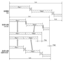
- FIG. 11 is a diagram showing a travel route set based on a route pattern. 11 is a graph showing the travel distances of an initial solution travel route, a set travel route, and a conditionally set travel route;
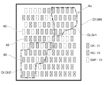
- FIG. 13 is a diagram showing groups divided according to the results of the supply status recognition process.
- the mounting assist device 50 assists the mounting process by the component mounting machine 10 using the bulk feeder 30.
- the mounting assist device 50 is incorporated into the control device 20 of the component mounting machine 10.
- the mounting assist device 50 aims to improve the efficiency of the picking cycle in accordance with the supply state of the components supplied by the bulk feeder 30.
- the component mounting machine 10 described above performs a mounting process for mounting components on the board 91 as a specified substrate-related operation.
- the component mounting machine 10 is installed in the transport direction of the board 91 together with other substrate-related operation machines to form a production line.
- Each of the multiple substrate-related operation machines is communicatively connected to a host computer 60 (see FIG. 4) that controls the production line as a whole.
- the production line includes, for example, a printing machine, the component mounting machine 10, a reflow oven, and an inspection machine as multiple substrate-related operation machines.
- Board transport device 11 1 the component mounting machine 10 includes a board transport device 11.
- the board transport device 11 sequentially transports boards 91 in a transport direction, and positions the boards 91 at predetermined positions within the machine.
- the component mounting machine 10 includes a component supplying device 12.
- the component supplying device 12 supplies components to be mounted on the board 91.
- the component supplying device 12 has feeders 122 set in a plurality of slots 121.
- the feeders 122 may be, for example, a tape feeder that feeds and moves a carrier tape containing a large number of components to supply the components so that they can be picked.
- the feeders 122 may be, for example, a bulk feeder 30 that supplies components stored in a bulk state so that they can be picked. Details of the bulk feeder 30 will be described later.
- the mounting head 133 supports multiple suction nozzles 134 that are rotatable and movable up and down.
- the suction nozzles 134 are holding members that pick up and hold the parts supplied by the feeder 122.
- the suction nozzles 134 use the supplied negative pressure air to pick up the parts supplied by the feeder 122.
- a chuck that holds the parts by gripping them can be used as the holding member attached to the mounting head 133.
- the component mounting machine 10 includes a component camera 14 and a board camera 15.
- the component camera 14 and the board camera 15 are digital imaging devices having imaging elements such as CMOS.
- the component camera 14 and the board camera 15 capture images based on a control signal and send image data acquired by the capture.
- the component camera 14 is configured to be able to capture images of the components held by the suction nozzle 134 from below.
- the board camera 15 is provided on a moving stage 132 so as to be movable in the horizontal direction integrally with the mounting head 133.
- the board camera 15 is configured to be able to capture images of the board 91 from above.
- the board camera 15 can also capture various devices within the movable range of the movable stage 132.
- the board camera 15 can capture images of the supply area As where the bulk feeder 30 supplies components and the reference mark 49 provided on the top of the bulk feeder 30 within the camera's field of view. In this way, the board camera 15 can be used to capture images of different objects in order to obtain image data to be used for various image processing.
- Control device 20 The component mounting machine 10 includes a control device 20.
- the control device 20 is mainly composed of a CPU, various memories, and a control circuit. As shown in Fig. 4, the control device 20 also includes a storage unit 21.
- the storage unit 21 is composed of a storage device such as a hard disk drive or a flash memory.
- the storage unit 21 of the control device 20 stores various data such as a control program M1 used to control the mounting process, component data M2, cavity information M3, and accommodation information M4.
- Control program M1 indicates the mounting positions, mounting angles, and component types of components to be mounted on board 91 in the planned mounting order during the mounting process.
- the mounting process includes a process of repeating a PP cycle (pick-and-place cycle), which includes a collection cycle and a mounting cycle, multiple times.
- the above-mentioned “collection cycle” refers to a process of repeating a collection operation, in which components supplied by component supply device 12 are picked up by suction nozzle 134, multiple times.
- the parts to be picked during the picking cycle may be supplied by the bulk feeder 30. If cavities 45 (see FIG. 3) that individually accommodate parts are formed in the supply area As of the bulk feeder 30, the picking cycle involves moving the mounting head 133 to pick up the parts accommodated in the multiple cavities 45 in sequence.
- the above-mentioned “mounting cycle” refers to the process of sequentially mounting the picked components on the board 91, and more specifically, the process of repeating a mounting operation multiple times to mount the picked components at a predetermined mounting position on the board 91 at a predetermined mounting angle.
- the control program M1 has preset therein the execution order of the PP cycle, which is made up of multiple picking operations and mounting operations that are grouped together taking into consideration the number of suction nozzles 134 supported by the mounting head 133, the travel distance of the mounting head 133, etc.
- Component data M2 includes shape data for each type of component.
- shape data includes at least one of the outer edge shape of the component, the shape of the characteristic part of the component, and the dimensions of the component.
- the "outer edge shape” of a component corresponds to the shape of the outer edge when the inside of the component and the background are separated using the outer edge as the boundary.
- the "shape of the characteristic part" of a part corresponds to the boundary shape of the characteristic part on the appearance resulting from the part's shape, pattern, color, etc.
- the characteristic part of a part may be the corners, bumps, terminals, leads, etc. of the part.
- the part data M2 may also include, for example, the maximum allowable movement speed (acceleration) for each part, the pick-up position (for example, the position of contact with the suction nozzle 134), etc.
- Cavity information M3 is information about the cavities 45 formed in the supply area As of the bulk feeder 30, associated with the identification information (ID) of the bulk feeder 30. Cavity information M3 may include the shape (including the length of each side and depth), position, orientation, and type of corresponding part of the cavity 45 in the supply area As.
- Accommodation information M4 is information indicating the positions of the multiple cavities 45 that accommodate parts so that they can be picked. Details of accommodation information M4 will be described later.
- the control device 20 executes a process for recognizing the holding state of the components held by each of the multiple holding members (suction nozzles 134). Specifically, the control device 20 processes image data acquired by imaging with the component camera 14, and recognizes the position and angle of each component relative to the reference position of the mounting head 133. Note that in addition to the component camera 14, the control device 20 may also process image data acquired by imaging the components from the side, below, or above using, for example, a head camera unit that is integrally provided with the mounting head 133.
- the control device 20 controls the mounting operation by the mounting head 133 so that the component is mounted on the board 91 in a specified orientation. At this time, the control device 20 controls the mounting operation based on the recognized holding state of the component. In other words, the control device 20 corrects the position of the mounting head 133 and the angle of the suction nozzle 134 about the Q axis so as to correct the positional and angular deviation of the component held by the suction nozzle 134 with respect to the Q axis (the rotation axis of the suction nozzle 134). As a result, the component held by the suction nozzle 134 is mounted at a specified mounting angle in a specified mounting position instructed by the control program M1.
- Bulk feeder 30 is set in component mounting machine 10 and functions as part of component supply device 12. Bulk feeder 30 supplies components housed in component cases in a bulk state (loose and irregular in each position) that is not packaged like a carrier tape. Therefore, unlike tape feeders, bulk feeder 30 does not use carrier tape, and therefore has the advantage of being able to omit loading of carrier tape and collection of used tape.
- Some types of bulk feeders 30 supply components in irregular positions to the planar supply area As, for example. However, if the components are so close together in the supply area As that they are touching each other, or if they are piled up (overlapping vertically), or if the components are in a horizontal position with their width direction aligned vertically, the component mounting machine 10 cannot pick up these components. Therefore, to increase the proportion of components that can be picked up, some types of bulk feeders 30 supply components in an aligned state in the supply area As. In this embodiment, a bulk feeder 30 that aligns components will be described as an example.
- the bulk feeder 30 has a track unit 40 that is vibrable and detachable from the feeder body 31, which is formed in a flat box shape.
- a connector 311 and two positioning pins 312 are provided at the front of the feeder body 31 (the right end in FIG. 2).
- the feeder body 31 When the feeder body 31 is set in the slot 121 of the component supply device 12, it is powered via the connector 311 and is capable of communicating with the control device 20 of the component mounting machine 10.
- the track unit 40 is vibrated by the vibration device 35.
- the track unit 40 is formed with a transport path R along which multiple parts are transported, and a supply area As that is connected to the transport path R and opens upward so that multiple parts can be picked up.
- the track unit 40 is formed to extend in the front-to-rear direction (left-to-right direction in Figure 3) of the feeder body 31.
- a pair of side walls 46 that protrude upward are formed on both edges of the track unit 40 in the width direction (top-bottom direction in Figure 3).
- the pair of side walls 46, together with the tip 47 of the track unit 40 are wall members that surround the periphery of the transport path R and prevent leakage of parts transported on the transport path R.
- a plurality of cavities 45 are formed in the supply area As of the track unit 40.
- Each of the plurality of cavities 45 opens upward and accommodates components in a position in which the thickness direction of the components is the up-down direction.
- the plurality of cavities 45 are arranged in a staggered pattern.
- the "supply area As" of the track unit 40 is an area where components are supplied in bulk, and where the components can be picked up by the suction nozzle 134 supported by the mounting head 133.
- the "transport path R" of the track unit 40 is a path along which the components that have circulated from the component case side to the track unit 40 are transported to the supply area As.
- the vibration device 35 also applies vibrations to the track unit 40 so that the multiple parts are transported along the transport path R.
- a forward and upward external force, or a rearward and upward external force is applied to the parts.
- the multiple parts are transported to the front or rear of the track unit 40.
- the bulk feeder 30 controls the operation of the vibration device 35 by the feeder control device 36 to transport the parts and perform the operation of supplying the parts to the supply area As.
- the parts are stored in the multiple cavities 45 by the supply operation, and the suction nozzle 134 is ready to pick up the parts.
- a shutter 48 capable of closing the opening of the supply area As is provided on the top of the track unit 40.
- the shutter 48 is in a state in which its opening and closing operation is controlled by a shutter drive device (not shown).
- a shutter drive device not shown.
- the mounting process by the component mounting machine 10 will be described with reference to Fig. 5.
- the bulk feeder 30 is set in the component supply device 12.
- the board transport device 11 of the component mounting machine 10 executes a loading process of the board 91 as shown in Fig. 5 (S11).
- the board 91 is loaded into the machine and positioned at a predetermined position within the machine.
- the bulk feeder 30 performs a component supply operation at a predetermined timing. After the component supply operation is performed, a process is performed to recognize the component supply status in the supply area As. The supply status recognition process will be described in detail later.
- control device 20 executes a PP cycle.
- the control device 20 executes a collection cycle in which the collection operation of collecting components using the multiple suction nozzles 134 is repeated (S12).
- the control device 20 controls the operation of the mounting head 133 in the collection operation so that the mounting head 133 is sequentially positioned according to the positions of the components that can be collected.
- the control device 20 positions the suction nozzle 134 by appropriately switching between the coordinate values of the center of the cavity 45 or the coordinate values of the reference position of the parts as the position of the pickable parts.
- the movement path of the mounting head 133 in the picking cycle (S12) is set by the mounting assistance device 50. The process of setting the movement path will be described in detail later.
- control device 20 executes a process for recognizing the holding state of the components held by each of the multiple suction nozzles 134 (S13).
- the control device 20 moves the mounting head 133 above the component camera 14 and sends an image capture command to the component camera 14.
- the control device 20 processes the image data acquired by the component camera 14, and recognizes the posture (position and angle) of the components held by each of the multiple suction nozzles 134.
- the control device 20 executes a mounting cycle in which the mounting operation of mounting components using the multiple suction nozzles 134 is repeated (S14).
- the control device 20 controls the operation of the mounting head 133 so that the components are mounted at the mounting positions specified by the control program. Furthermore, the control device 20 controls the operation of the mounting head 133 so that the suction nozzles 134 are positioned and angled relative to the mounting positions based on the results of the recognition process (S13).
- the control device 20 determines whether all PP cycles have been completed based on the control program (S15). If all PP cycles have not been completed (S15: No), the control device 20 executes the PP cycle (S12-S14). If all PP cycles have been completed (S15: Yes), the control device 20 executes the unloading process of the board 91 (S16). In the unloading process of the board 91, the board transport device 11 unclamps the positioned board 91 and unloads the board 91 out of the component mounting machine 10.
- the configuration of the mounting support device 50 will be described with reference to Fig. 4 and Fig. 6 to Fig. 11.
- the mounting support device 50 supports the picking cycle executed by the control device 20 of the component mounting machine 10 in the mounting process.
- image processing is first performed to recognize the supply state of the components by the bulk feeder 30, and the component picking operation using the suction nozzle 134 is controlled based on the result of the image processing.
- the multiple cavities 45 are arranged in a cavity row consisting of multiple cavities 45 arranged along a first direction (X direction in this embodiment), lined up in a second direction (Y direction in this embodiment) intersecting the X direction. Therefore, as for the above-mentioned movement path, first, the cavity 45 located at one end in the X direction among the multiple cavities 45 in the cavity row closest to the substrate 91 toward the other end in the X direction is set as the starting position of the collection operation, which first contains a cavity 45 capable of collecting a component.
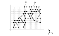
- a meandering movement path can be set that moves from the cavity 45 at the start position to the other end in the X direction, then moves to the adjacent cavity row in the Y direction, and then moves toward the one end in the X direction (see FIG. 9A).
- the above-mentioned movement path can be said to be efficient when the multiple cavities 45 that house components that can be picked are distributed evenly.
- the multiple cavities 45 that house components that can be picked may be unevenly distributed in the supply area As, and there may be a movement path that is more efficient than the above-mentioned movement path setting method. Therefore, the mounting assistance device 50 adopts a configuration that supports the mounting process by improving the efficiency of the picking cycle according to the supply status of components by the bulk feeder 30.
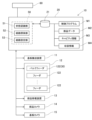
- the mounting assistance device 50 includes a state recognition unit 51, a path search unit 52, and a path setting unit 53, as shown in FIG. 4.
- the state recognition unit 51 executes the supply state recognition process (S20) shown in FIG. 6.
- the path search unit 52 and the path setting unit 53 execute the movement path setting process (S30) shown in FIG. 8.
- the control device 20 controls the operation of the mounting head 133 in the collection cycle according to the movement path set by the setting process.
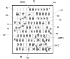
- State recognition unit 51 The state recognition unit 51 performs image processing on image data D1 (see FIG. 7A ) acquired by imaging the supply area As of the components 92 in the bulk feeder in which the multiple cavities 45 are formed, recognizes the supply state of the components 92 in the supply area As, and generates accommodation information M4.
- the supply state of the components 92 includes a determination result as to whether the components 92 supplied to the supply area As of the bulk feeder 30 are suitable for the picking operation by the component mounting machine 10.
- the state recognition unit 51 acquires image data D1 by capturing an image with a camera (in this embodiment, the board camera 15) (S21).
- a camera in this embodiment, the board camera 15
- S21 the state recognition unit 51
- the state recognition unit 51 performs image processing on the image data D1 to perform recognition processing on the parts 92 in the image data D1 (S22). More specifically, the state recognition unit 51 recognizes the parts 92 included in the image data D1, for example, by blob analysis. The state recognition unit 51 binarizes the image data D1 using a predetermined threshold value to generate blobs. The state recognition unit 51 recognizes the parts 92 based on the size and shape of the generated blobs and the part data M2.
- the state recognition unit 51 executes a process for determining whether the recognized component 92 can be picked (S23).
- this determination process is a determination as to whether the recognized component 92 is suitable for the picking operation by the component mounting machine 10. In other words, if a component 92 is present in the supply area As but is not contained in the cavity 45 or is in contact with other components 92, it is determined that it cannot be picked (is not suitable for the picking operation).
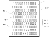
- the state recognition unit 51 records the recognition result of the supply state as storage information M4 (S24). In this embodiment, the state recognition unit 51 determines the state for each of the multiple cavities 45. As a result, the multiple cavities 45 are classified into storage cavities that can store components 92 so that they can be picked (shown with diagonal lines in FIG. 7B, "OK"), NG cavities that cannot be picked even though components 92 are present around them (shown with diagonal X marks in FIG. 7B, "NG”), and empty cavities that do not have components 92 present around them (shown with dashed lines in FIG. 7B, "EMP"). The state recognition unit 51 calculates the number (V1, V2, V3) of each state (OK, NG, EMP) of the multiple cavities 45.
- This storage information M4 indicates the positions of the multiple cavities 45 that can store parts that can be picked up. Furthermore, in the supply status recognition process, if there is a part that is suitable for the picking operation, the status recognition unit 51 recognizes the position and angle of that part. Thus, in addition to the status of each cavity 45 (OK, NG, EMP), the storage information M4 records the position (e.g., the center coordinates of the part) and angle (e.g., the inclination angle of the cavity 45 relative to a reference angle) of the pickable part in the cavity 45.
- position e.g., the center coordinates of the part
- angle e.g., the inclination angle of the cavity 45 relative to a reference angle
- the above-mentioned supply status recognition process (S20) is executed after the bulk feeder 30 has performed the supply operation of the components 92.
- the status recognition unit 51 can execute the recognition process, for example, in parallel with the board loading process (S11) or the PP cycle, to generate the storage information M4.
- the storage information M4 is updated in accordance with the picking operation, and is discarded when the bulk feeder 30 has performed the supply operation of the components 92.
- the path search unit 52 searches for a path pattern that is a candidate for the movement path of the mounting head 133 in the collection cycle based on the accommodation information M4.
- the "movement path” refers to the path along which the mounting head 133 moves in the XY direction to pick up components 92 from the multiple cavities 45 in the collection cycle of the PP cycle, and indicates the positions and order of the multiple cavities 45 in which the mounting head 133 is positioned.
- the mounting head 133 moves along the movement path Nr to a predetermined cavity 45.
- the control device 20 adjusts the position of the mounting head 133 and the angle of the suction nozzle 134, taking into account the position and angle of the component 92 contained in the cavity 45.
- a "route pattern" is a candidate for the movement route Nr that is searched for before the final movement route Nr is set. For example, a route having two cavities 45 as its start and end points in a specified route pattern is searched for by swapping the start or end points with another route.
- the route search unit 52 searches for a route pattern based on specified conditions from the viewpoint of improving the efficiency of the collection cycle.
- Path setting unit 53 The path setting unit 53 sets, as the movement path Nr, a path pattern selected based on the movement distance Lm of the mounting head 133 calculated for each of the multiple path patterns. In detail, the path setting unit 53 calculates the sum of the lengths of the routes included in the path pattern as the movement distance Lm of the mounting head 133.
- the movement distance Lm roughly corresponds to the movement distance of the mounting head 133 moving along the movement path Nr set for that path pattern, and correlates with the time required for the collection cycle.
- the evaluation by the path setting unit 53 using the movement distance Lm for each path pattern is synonymous with the evaluation using the time required for the collection cycle calculated for each path pattern.
- the movement path setting process (S30) by the mounting support device 50 will be described.
- the movement path setting process (S30) is executed after the bulk feeder 30 executes the supply operation of the components 92 and the supply state recognition process (S20) is completed.
- the supply area As of the bulk feeder 30 is imaged and image data D1 is acquired after the mounting cycle of the first PP cycle is completed.
- a supply status recognition process (S20) is executed, and then a movement path setting process (S30) is executed.
- the mounting head 133 can execute the above processes (S20, S30) in parallel with the above processes for the picking operation of the components 92 supplied by the feeder 122 during the picking cycle of the second PP cycle, which does not require the result of the movement path setting process (S30).
- the path search unit 52 first acquires various information (S31).
- the various information may include the control program M1, the part data M2, the cavity information M3, and the conditions and parameters used to set the movement path, in addition to the accommodation information M4 indicating the positions of the multiple cavities 45 that accommodate the parts 92 so that they can be picked up.
- the path search unit 52 determines the first cavity (S32, determination step).
- the "first cavity” refers to the cavity 45 from which the mounting head 133 first picks up the component 92 in the path pattern Hr, among the multiple cavities 45 that accommodate the component 92 so that it can be picked up. In other words, it is the position that is the starting point of all path patterns Hr.
- the path search unit 52 may set the first cavity Cf based on the position of the mounting head 133 when the picking cycle begins.
- the first cavity Cf is determined to be the accommodating cavity that includes at least one of the multiple cavity rows and is closest to the current position of the mounting head 133 in the cavity row that is closest to the substrate 91.
- the mounting head 133 can start moving toward the first cavity Cf. This allows the mounting head 133 to move without waiting for the movement path setting process (S30) to finish, preventing waiting time from occurring.
- the path search unit 52 and the path setting unit 53 search for the path pattern Hr and set the movement path Nr using an algorithm applied to solving the traveling salesman problem.
- the path search unit 52 and the path setting unit 53 treat the multiple cavities 45 that store the parts 92 so that they can be picked as nodes, and treat a combination of routes that visit these once each as one path pattern Hr, and evaluate the sum of the lengths of the routes as the movement distance of the mounting head 133 in the path pattern Hr.
- the NN (Neural Network) method and the 2-opt method are known algorithms that can be applied to solve the above-mentioned traveling salesman problem. It is possible to arbitrarily set which algorithm to apply. For example, if an algorithm that is likely to experimentally obtain an optimal solution depending on the supply state of parts 92 (proportion of accommodating cavities, degree of bias of accommodating cavities) is known in advance, the algorithm to be applied may be switched depending on the recognized supply state.
- the path search unit 52 uses the first cavity Cf as a reference. Then, the path search unit 52 sets an initial solution for the algorithm (S33).
- the path search unit 52 provides the algorithm with a preliminary path Ni formed by connecting the ends of paths (paths in the X direction) along adjacent cavity rows with a path along the Y direction as an initial solution.
- This preliminary path Ni which is the initial solution, corresponds to the movement path before the mounting assistance device 50 is used to improve efficiency, as shown in FIG. 9A.
- the path search unit 52 searches for a path pattern Hr obtained by changing the route from the initial solution using the first cavity Cf as a reference (fixed starting point) (S34, path search process). At this time, if the mounting head 133 has started moving toward the first cavity Cf, the path search unit 52 executes the search process (S34) during the period in which the mounting head 133 is moving. Then, when the path search unit 52 generates the path pattern Hr as a search result, the path search unit 52 executes a movement path setting process (S35, path setting process).
- the path setting unit 53 compares the travel distance Lm (sum of the route lengths) of the mounting head 133 in the preliminary path Ni, which is the initial solution, with the travel distance Lm of the mounting head 133 in the searched path pattern Hr, and if a difference Fd1 exists and the travel distance Lm is shorter, sets this path pattern Hr as the provisional travel path Nr.
- the path setting unit 53 updates the travel path Nr by overwriting it each time the travel distance Lm of the mounting head 133 in the next generated path pattern Hr becomes shorter.
- the search for the path pattern is not complete (S36: No)
- the above process (S34-S35) is repeated.
- the search for the path pattern is complete (S36: Yes)
- the finally set movement path Nr is applied to the movement of the mounting head 133 in the collection cycle. Note that the end of the search for the path pattern mentioned above includes cases where the search is terminated due to the progress of the collection cycle, as well as cases where all path patterns (excluding obviously redundant patterns) have been searched for by the algorithm.
- a movement path Nr as shown in FIG. 9B is set by the above algorithm for the movement path Nr (FIG. 9A) for which the preliminary path Ni is set as the initial solution. Then, if a collection cycle is being executed in parallel with the movement path setting process (S30), the mounting head 133 is moved along the provisionally set movement path Nr. Then, during the execution period of the collection cycle, the path search unit 52 continues to search for a path pattern Hr (S34), and the path setting unit 53 continues to set a movement path Nr (S35), for the portion of the movement path Nr that the mounting head 133 has not yet reached.
- the control device 20 of the component mounting machine 10 moves the mounting head 133 along the movement path Nr that is currently determined to be the best by the mounting assistance device 50, and if a more efficient movement path Nr is set for the unreached portion of the mounting head 133 by the end of the collection cycle, it moves the mounting head 133 along that movement path Nr.
- the collection cycle ends, there are no more unreached portions of the movement path Nr, and the search for the path pattern ends.
- the above-described configuration of the mounting assistance device 50 can shorten the movement distance Lm of the mounting head 133 during the collection cycle, thereby improving the efficiency of the collection cycle and the mounting process.
- the path search unit 52 may search for a path pattern Hr based on the accommodation information M4 and the required number Ra of parts 92 to be collected in the scheduled collection cycle.
- the path search unit 52 imposes a condition that the required number Ra is the number of nodes in the traveling salesman problem.
- a movement path Nr for collecting the required number Ra in the most recent collection cycle is set, which makes it possible to improve the efficiency of the process of setting the movement path Nr, and also improves the search speed as the number of nodes decreases, which is expected to optimize the movement path Nr.
- the collectable number Vc is greater than the sum of the required numbers Ra1 and Ra2 of parts 92 to be collected by the collection cycle scheduled to be executed in successive PP cycles, the path search unit 52 may add a condition to the algorithm that sets the required numbers Ra1 and Ra2 as the number of nodes.
- the movement path Nr is set so that the route length between nodes during successive PP cycles (the length of the blocks shown with diagonal X marks in Figure 10) is as short as possible.
- the mounting head 133 actually moves toward the substrate 91, shortening the route length between nodes during successive PP cycles does not contribute to overall efficiency. Therefore, by adding a condition that takes into account the required number Ra as described above, the route length between successive PP cycles is allowed to be longer, and a movement path Nr is set that prioritizes shortening the movement distance Lm of the mounting head 133 in the collection cycle.
- the total travel distance Lm is longer by the difference Fd2 compared to the initial efficiency solution, but the travel distance Lm of the mounting head 133 in the collection cycle is shorter by the difference FdV, which is effective.
- the path pattern search process S34
- the path search unit 52 may impose conditions assuming that the storage cavities may be biased in the supply area As of the bulk feeder 30. Specifically, the path search unit 52 first divides the multiple cavities 45 (storage cavities) that store the parts 92 shown in the storage information M4 in a manner that allows them to be picked into multiple groups Gr (Gr1, Gr2) as shown in FIG. 11. Note that, as a method of setting the groups Gr, for example, a method of searching for a closed area that contains a preset allowable number of NG cavities and empty cavities based on a portion where a predetermined number of storage cavities are consecutive in at least one of the X and Y directions is used as a criterion.
- the path search unit 52 searches for a path pattern Hr based on the number of cavities 45 (number of containing cavities) included in each of the multiple groups Gr (Gr1, Gr2) and the required number Ra (Ra1, Ra2) of parts 92 to be collected by the planned collection cycle.
- a path pattern is searched for within a group Gr that can secure the required number Ra, so the process of setting the movement path Nr can be made more efficient, and the search speed improves as the number of nodes decreases, which is expected to optimize the movement path Nr.
- the path search unit 52 may apply a path pattern search method that does not use the group Gr in the process of setting the movement path Nr for the most recent PP cycle when, for example, the number of collectables Vc is greater than the number of required Ra (Ra1, Ra2) in the collection cycle of the consecutive PP cycles to be executed. This allows the movement of the mounting head 133 in the collection cycle executed in parallel with the process of setting the movement path to be prioritized.
- the method of searching for a path pattern with the group Gr as a condition may be switched to apply.
- the algorithm and conditions may be appropriately switched to make the process of setting the movement path Nr more efficient and to optimize the movement path Nr.
- the mounting assist device 50 is configured to be incorporated in the control device 20 of the component mounting machine 10. However, a part or all of the mounting assist device 50 may be incorporated in the host computer 60 or other external device. For example, the mounting assist device 50 may be incorporated in the host computer 60 and may be a dedicated device installed on the production line Ln.
Landscapes
- Engineering & Computer Science (AREA)
- Manufacturing & Machinery (AREA)
- Microelectronics & Electronic Packaging (AREA)
- Supply And Installment Of Electrical Components (AREA)
Abstract
装着支援装置は、装着ヘッドを移動させて複数のキャビティに収容された部品を順次採取する採取サイクル、および複数の部品を基板に順次装着する装着サイクルを実行する部品装着機に適用され、複数のキャビティのうち部品を採取可能に収容する複数のキャビティの位置を示す収容情報に基づいて、採取サイクルにおける装着ヘッドの移動経路の候補である経路パターンを探索する経路探索部と、複数の経路パターンごとに算出された装着ヘッドの移動距離に基づいて選択された経路パターンを移動経路に設定する経路設定部と、を備える。
Description
本発明は、装着支援装置および装着支援方法に関するものである。
装着支援装置は、バルクフィーダを用いた部品装着機による装着処理を支援する。バルクフィーダは、基板に部品を装着する部品装着機に装備され、バルク状態の部品を供給する(特許文献1を参照)。部品装着機は、装着処理において、装着ヘッドを移動させて複数のキャビティに収容された部品を順次採取する採取サイクル、および複数の前記部品を基板に順次装着する装着サイクルを実行する。
ここで、部品装着機は、装着処理において、バルクフィーダによる部品の供給状態を認識する画像処理を実行し、その画像処理の結果に基づいて吸着ノズルを用いた部品の吸着動作を制御する。部品装着機には、装着処理の所要時間の短縮が望まれている。
本明細書は、バルクフィーダによる部品の供給状態に応じた採取サイクルの効率化を図ることにより装着処理を支援する装着支援装置および装着支援方法を提供することを目的とする。
本明細書は、装着ヘッドを移動させて複数のキャビティに収容された部品を順次採取する採取サイクル、および複数の前記部品を基板に順次装着する装着サイクルを実行する部品装着機に適用され、複数の前記キャビティのうち前記部品を採取可能に収容する複数の前記キャビティの位置を示す収容情報に基づいて、前記採取サイクルにおける前記装着ヘッドの移動経路の候補である経路パターンを探索する経路探索部と、複数の前記経路パターンごとに算出された前記装着ヘッドの移動距離に基づいて選択された前記経路パターンを前記移動経路に設定する経路設定部と、を備える装着支援装置を開示する。
本明細書は、装着ヘッドを移動させて複数のキャビティに収容された部品を順次採取する採取サイクル、および複数の前記部品を基板に順次装着する装着サイクルを実行する部品装着機に適用され、複数の前記キャビティのうち前記部品を採取可能に収容する複数の前記キャビティの位置を示す収容情報に基づいて、前記採取サイクルにおける前記装着ヘッドの移動経路の候補である経路パターンを探索する経路探索工程と、複数の前記経路パターンごとに算出された前記装着ヘッドの移動距離に基づいて選択された前記経路パターンを前記移動経路に設定する経路設定工程と、を備える装着支援方法を開示する。
本明細書では、出願当初の請求項4において「請求項1または2に記載の装着支援装置」を「請求項1-3の何れか一項に記載の装着支援装置」に変更した技術的思想や、出願当初の請求項5において「請求項1または2に記載の装着支援装置」を「請求項1-4の何れか一項に記載の装着支援装置」に変更した技術的思想も開示されている。また、本明細書では、出願当初の請求項7において「請求項5に記載の装着支援装置」を「請求項5または6に記載の装着支援装置」に変更した技術的思想や、出願当初の請求項8において「請求項1または2に記載の装着支援装置」を「請求項1-7の何れか一項に記載の装着支援装置」に変更した技術的思想も開示されている。また、本明細書では、出願当初の請求項9において「請求項1または2に記載の装着支援装置」を「請求項1-8の何れか一項に記載の装着支援装置」に変更した技術的思想や、出願当初の請求項11において「請求項1または2に記載の装着支援装置」を「請求項1-10の何れか一項に記載の装着支援装置」に変更した技術的思想も開示されている。
このような構成によると、採取サイクルにおける装着ヘッドの移動距離の短縮を図ることができるので、採取サイクルおよび装着処理の効率化を図ることができる。
1.装着支援装置50の概要
装着支援装置50は、バルクフィーダ30を用いた部品装着機10による装着処理を支援する。本実施形態において、装着支援装置50は、部品装着機10の制御装置20に組み込まれる。装着支援装置50は、バルクフィーダ30により供給された部品の供給状態に応じた採取サイクルの効率化を図るものである。
装着支援装置50は、バルクフィーダ30を用いた部品装着機10による装着処理を支援する。本実施形態において、装着支援装置50は、部品装着機10の制御装置20に組み込まれる。装着支援装置50は、バルクフィーダ30により供給された部品の供給状態に応じた採取サイクルの効率化を図るものである。
上記の部品装着機10は、基板91に部品を装着する装着処理を、所定の対基板作業として実行する。部品装着機10は、他の対基板作業機とともに基板91の搬送方向に設置され生産ラインを構成する。複数の対基板作業機のそれぞれは、生産ラインを統括して制御するホストコンピュータ60(図4を参照)に通信可能に接続される。生産ラインは、例えば、複数の対基板作業機としての印刷機、部品装着機10、リフロー炉、および検査機を備える。
2.部品装着機10の構成
2-1.基板搬送装置11
部品装着機10は、図1に示すように、基板搬送装置11を備える。基板搬送装置11は、基板91を搬送方向へと順次搬送するとともに、基板91を機内の所定位置に位置決めする。
2-1.基板搬送装置11
部品装着機10は、図1に示すように、基板搬送装置11を備える。基板搬送装置11は、基板91を搬送方向へと順次搬送するとともに、基板91を機内の所定位置に位置決めする。
2-2.部品供給装置12
部品装着機10は、部品供給装置12を備える。部品供給装置12は、基板91に装着される部品を供給する。部品供給装置12は、複数のスロット121にフィーダ122をそれぞれセットされる。フィーダ122には、例えば多数の部品が収納されたキャリアテープを送り移動させて、部品を採取可能に供給するテープフィーダが適用される。また、フィーダ122には、バルク状態で収容された部品を採取可能に供給するバルクフィーダ30が適用される。バルクフィーダ30の詳細については後述する。
部品装着機10は、部品供給装置12を備える。部品供給装置12は、基板91に装着される部品を供給する。部品供給装置12は、複数のスロット121にフィーダ122をそれぞれセットされる。フィーダ122には、例えば多数の部品が収納されたキャリアテープを送り移動させて、部品を採取可能に供給するテープフィーダが適用される。また、フィーダ122には、バルク状態で収容された部品を採取可能に供給するバルクフィーダ30が適用される。バルクフィーダ30の詳細については後述する。
2-3.部品移載装置13
部品装着機10は、部品移載装置13を備える。部品移載装置13は、部品供給装置12により供給された部品を基板91上の所定の装着位置に移載する。部品移載装置13は、ヘッド駆動装置131、移動台132、装着ヘッド133、および吸着ノズル134を備える。ヘッド駆動装置131は、直動機構により移動台132を水平方向(X方向およびY方向)に移動させる。装着ヘッド133は、図示しないクランプ部材により移動台132に着脱可能に固定され、機内を水平方向に移動可能に設けられる。
部品装着機10は、部品移載装置13を備える。部品移載装置13は、部品供給装置12により供給された部品を基板91上の所定の装着位置に移載する。部品移載装置13は、ヘッド駆動装置131、移動台132、装着ヘッド133、および吸着ノズル134を備える。ヘッド駆動装置131は、直動機構により移動台132を水平方向(X方向およびY方向)に移動させる。装着ヘッド133は、図示しないクランプ部材により移動台132に着脱可能に固定され、機内を水平方向に移動可能に設けられる。
装着ヘッド133は、回転可能に且つ昇降可能に複数の吸着ノズル134を支持する。吸着ノズル134は、フィーダ122により供給される部品を採取して保持する保持部材である。吸着ノズル134は、供給される負圧エアにより、フィーダ122により供給される部品を吸着する。装着ヘッド133に取り付けられる保持部材としては、部品を把持することにより保持するチャックなどが採用され得る。
2-4.部品カメラ14、基板カメラ15
部品装着機10は、部品カメラ14、および基板カメラ15を備える。部品カメラ14、および基板カメラ15は、CMOSなどの撮像素子を有するデジタル式の撮像装置である。部品カメラ14、および基板カメラ15は、制御信号に基づいて撮像を行い、当該撮像により取得した画像データを送出する。部品カメラ14は、吸着ノズル134に保持された部品を下方から撮像可能に構成される。基板カメラ15は、装着ヘッド133と一体的に水平方向に移動可能に移動台132に設けられる。基板カメラ15は、基板91を上方から撮像可能に構成される。
部品装着機10は、部品カメラ14、および基板カメラ15を備える。部品カメラ14、および基板カメラ15は、CMOSなどの撮像素子を有するデジタル式の撮像装置である。部品カメラ14、および基板カメラ15は、制御信号に基づいて撮像を行い、当該撮像により取得した画像データを送出する。部品カメラ14は、吸着ノズル134に保持された部品を下方から撮像可能に構成される。基板カメラ15は、装着ヘッド133と一体的に水平方向に移動可能に移動台132に設けられる。基板カメラ15は、基板91を上方から撮像可能に構成される。
また、基板カメラ15は、基板91の表面を撮像対象とする他に、移動台132の可動範囲であれば種々の機器などを撮像対象にできる。例えば、基板カメラ15は、本実施形態において、図3に示すように、バルクフィーダ30が部品を供給する供給領域Asやバルクフィーダ30の上部に設けられた基準マーク49をカメラ視野に収めて撮像することができる。このように、基板カメラ15は、種々の画像処理に用いられる画像データを取得するために、異なる撮像対象の撮像に兼用され得る。
2-5.制御装置20
部品装着機10は、制御装置20を備える。制御装置20は、主として、CPUや各種メモリ、制御回路により構成される。制御装置20は、図4に示すように、記憶部21を備える。記憶部21は、ハードディスク装置またはフラッシュメモリなどの記憶装置により構成される。制御装置20の記憶部21には、装着処理の制御に用いられる制御プログラムM1や部品データM2、キャビティ情報M3、収容情報M4などの各種データが記憶される。
部品装着機10は、制御装置20を備える。制御装置20は、主として、CPUや各種メモリ、制御回路により構成される。制御装置20は、図4に示すように、記憶部21を備える。記憶部21は、ハードディスク装置またはフラッシュメモリなどの記憶装置により構成される。制御装置20の記憶部21には、装着処理の制御に用いられる制御プログラムM1や部品データM2、キャビティ情報M3、収容情報M4などの各種データが記憶される。
制御プログラムM1は、装着処理において基板91に装着される部品の装着位置、装着角度、および部品種類を予定される装着順で示す。ここで、装着処理には、採取サイクルと装着サイクルとが含まれるPPサイクル(ピックアンドプレースサイクル)を複数回に亘って繰り返す処理が含まれる。上記の「採取サイクル」とは、部品供給装置12により供給された部品を吸着ノズル134により採取する採取動作を、複数回に亘り繰り返す処理である。
ここで、採取サイクルにおいて採取対象の部品がバルクフィーダ30により供給されていることがある。そして、バルクフィーダ30の供給領域Asに部品を個々に収容するキャビティ45(図3を参照)が形成されている場合には、採取サイクルは、装着ヘッド133を移動させて複数のキャビティ45に収容された部品を順次採取する動作となる。
また、上記の「装着サイクル」とは、採取した部品を基板91に順次装着する処理であり、詳細には、基板91の所定の装着位置に、所定の装着角度で装着する装着動作を、複数回に亘り繰り返す処理である。このように、制御プログラムM1には、装着ヘッド133が支持する吸着ノズル134の数や、装着ヘッド133の移動距離などを考慮してグループ化された複数回の採取動作および装着動作により構成されるPPサイクルの実行順序が予め設定されている。
部品データM2には、部品の種類ごとの形状データが含まれる。上記の「形状データ」には、部品の外縁形状、部品の特徴部の形状、および部品の寸法の少なくとも一つが含まれる。部品の「外縁形状」とは、部品の外縁を境界として部品の内側と背景とを区分したときの当該外縁の形状に相当する。
部品の「特徴部の形状」とは、部品が有する形状、模様、色彩などに起因する外観上の特徴部の境界形状に相当する。部品の特徴部としては、部品の角部やバンプ、端子、リード部などが適用され得る。また、部品データM2には、形状データの他に、例えば部品ごとの最大の許容移動速度(加速度)、採取位置(例えば、吸着ノズル134に接触する位置)などが含まれ得る。
キャビティ情報M3は、バルクフィーダ30の供給領域Asに形成されたキャビティ45に関する情報が、バルクフィーダ30の識別情報(ID)に関連付けられたものである。キャビティ情報M3には、供給領域Asにおけるキャビティ45の形状(各辺長さおよび深さを含む)、位置、向き、対応する部品の種類などが含まれ得る。収容情報M4は、複数のキャビティ45のうち部品を採取可能に収容する複数のキャビティ45の位置を示す情報である。収容情報M4の詳細については後述する。
制御装置20は、複数の保持部材(吸着ノズル134)のそれぞれに保持された部品の保持状態の認識処理を実行する。具体的には、制御装置20は、部品カメラ14の撮像により取得された画像データを画像処理し、装着ヘッド133の基準位置に対する各部品の位置および角度を認識する。なお、制御装置20は、部品カメラ14の他に、例えば装着ヘッド133に一体的に設けられるヘッドカメラユニットなどが部品を側方、下方、または上方から撮像して取得された画像データを画像処理するようにしてもよい。
制御装置20は、装着処理において、基板91に部品が所定の姿勢で装着されるように装着ヘッド133による装着動作を制御する。このとき、制御装置20は、認識した部品の保持状態に基づいて装着動作を制御する。つまり、制御装置20は、吸着ノズル134に保持された部品のQ軸(吸着ノズル134の自転軸)に対する位置および角度のずれを補正するように、装着ヘッド133の位置、および吸着ノズル134のQ軸回りの角度を補正する。結果として、吸着ノズル134に保持された部品が制御プログラムM1により指示される所定の装着位置に所定の装着角度で装着される。
3.バルクフィーダ30の構成
バルクフィーダ30は、部品装着機10にセットされて部品供給装置12の一部として機能する。バルクフィーダ30は、キャリアテープのようには包装されていないバルク状態(それぞれの姿勢が不規則なばら状態)で部品ケースに収容された部品を供給する。そのため、バルクフィーダ30は、テープフィーダと異なりキャリアテープを用いないため、キャリアテープの装填や使用済みテープの回収などを省略できる点でメリットがある。
バルクフィーダ30は、部品装着機10にセットされて部品供給装置12の一部として機能する。バルクフィーダ30は、キャリアテープのようには包装されていないバルク状態(それぞれの姿勢が不規則なばら状態)で部品ケースに収容された部品を供給する。そのため、バルクフィーダ30は、テープフィーダと異なりキャリアテープを用いないため、キャリアテープの装填や使用済みテープの回収などを省略できる点でメリットがある。
バルクフィーダ30には、例えば平面状の供給領域Asに不規則な姿勢で部品を供給するタイプがある。しかしながら、供給領域Asにおいて部品同士が接触するほど接近していたり堆積(上下方向に重なり合っている状態)していたり、部品の幅方向が上下方向となるような横立ち姿勢であったりすると、部品装着機10は、これらの部品を採取対象にすることができない。そこで、採取可能な部品の割合を増加すべく、バルクフィーダ30には、供給領域Asにおいて部品を整列させた状態で供給するタイプがある。本実施形態では、部品を整列させるタイプのバルクフィーダ30を例示して説明する。
バルクフィーダ30は、扁平な箱状に形成されたフィーダ本体31に対して振動可能に且つ着脱可能に軌道ユニット40が設けられる。フィーダ本体31の前部(図2の右側端部)には、コネクタ311および2つの位置決め用のピン312が設けられる。フィーダ本体31は、部品供給装置12のスロット121にセットされると、コネクタ311を介して給電されるとともに、部品装着機10の制御装置20と通信可能な状態となる。
軌道ユニット40は、加振装置35により振動を付与される。軌道ユニット40は、複数の部品が搬送される搬送路R、および搬送路Rに連通して複数の部品を採取可能に上方に開口する供給領域Asを形成される。軌道ユニット40は、フィーダ本体31の前後方向(図3の左右方向)に延伸するように形成される。軌道ユニット40の幅方向(図3の上下方向)の両縁には、上方に突出する一対の側壁46が形成される。一対の側壁46は、軌道ユニット40の先端部47とともに搬送路Rの周縁を囲い、搬送路Rを搬送される部品の漏出を防止する壁部材である。
軌道ユニット40の供給領域Asには、図3に示すように、複数のキャビティ45が形成されている。複数のキャビティ45のそれぞれは、上方に開口し、部品の厚み方向が上下方向となる姿勢で部品を収容する。本実施形態において、複数のキャビティ45は、千鳥状をなすように配置されている。ここで、軌道ユニット40の「供給領域As」とは、部品をバルク状態で供給する領域であって、装着ヘッド133に支持された吸着ノズル134により部品を採取可能な領域である。また、軌道ユニット40の「搬送路R」とは、部品ケース側から軌道ユニット40へと流通した部品が供給領域Asへと搬送される部品の通り道である。
また、上記の加振装置35は、複数の部品が搬送路Rに沿って搬送されるように軌道ユニット40に振動を付与する。軌道ユニット40が振動すると、部品には前方且つ上方の外力、または後方且つ上方の外力を加えられる。結果として、複数の部品は、軌道ユニット40の前側に搬送されたり、後側に搬送されたりすることになる。バルクフィーダ30は、フィーダ制御装置36により加振装置35の動作を制御して部品を搬送し、供給領域Asへの部品の供給動作を実行する。供給動作により複数のキャビティ45に部品が収容されることにより、吸着ノズル134が部品を採取可能な状態となる。
軌道ユニット40の上部には、供給領域Asの開口を閉塞可能なシャッタ48が設けられる。シャッタ48は、軌道ユニット40がフィーダ本体31に取り付けられると、図略のシャッタ駆動装置により開閉動作を制御される状態となる。バルクフィーダ30は、シャッタ48を開閉することによって部品の飛び出しや供給領域Asへの異物混入を防止することができる。
4.部品装着機10による装着処理
部品装着機10による装着処理について、図5を参照して説明する。ここで、部品供給装置12には、バルクフィーダ30がセットされているものとする。装着処理において、先ず、部品装着機10の基板搬送装置11は、図5に示すように、基板91の搬入処理を実行する(S11)。これにより、機内に基板91が搬入されるとともに、機内の所定位置に位置決めされる。
部品装着機10による装着処理について、図5を参照して説明する。ここで、部品供給装置12には、バルクフィーダ30がセットされているものとする。装着処理において、先ず、部品装着機10の基板搬送装置11は、図5に示すように、基板91の搬入処理を実行する(S11)。これにより、機内に基板91が搬入されるとともに、機内の所定位置に位置決めされる。
なお、装着処理に並行して、所定のタイミングでバルクフィーダ30による部品の供給動作が実行される。この部品の供給動作の実行後に、供給領域Asにおける部品の供給状態を認識する処理が実行される。供給状態の認識処理の詳細については後述する。
次に、制御装置20は、PPサイクルを実行する。PPサイクルにおいて、制御装置20は、複数の吸着ノズル134を用いて部品を採取する採取動作を繰り返す採取サイクルを実行する(S12)。このとき、制御装置20は、採取可能な部品の位置に応じて装着ヘッド133を順次位置決めするように、採取動作における装着ヘッド133の動作を制御する。
また、制御装置20は、採取対象の部品をバルクフィーダ30が供給している場合には、採取可能な部品の位置として、キャビティ45の中心である座標値、または部品の基準位置の座標値を適宜切り換えて、吸着ノズル134を位置決めする。なお、採取サイクル(S12)における装着ヘッド133の移動経路については、装着支援装置50により設定される。移動経路の設定処理の詳細については後述する。
続いて、制御装置20は、複数の吸着ノズル134にそれぞれ保持された部品の保持状態の認識処理を実行する(S13)。詳細には、制御装置20は、装着ヘッド133を部品カメラ14の上方に移動させ、部品カメラ14に撮像指令を送出する。制御装置20は、部品カメラ14の撮像により取得された画像データを画像処理して、複数の吸着ノズル134のそれぞれに保持された部品の姿勢(位置および角度)を認識する。
その後に、制御装置20は、複数の吸着ノズル134を用いて部品を装着する装着動作を繰り返す装着サイクルを実行する(S14)。なお、この装着サイクル(S14)の装着動作では、制御装置20は、制御プログラムにて指定される装着位置に、部品をそれぞれ装着するように装着ヘッド133の動作を制御する。さらに、制御装置20は、装着位置に対して、認識処理(S13)の結果に基づいて、吸着ノズル134が位置決めおよび角度決めされるように装着ヘッド133の動作を制御する。
制御装置20は、制御プログラムに基づいて、全てのPPサイクルが終了したか否かを判定する(S15)。全てのPPサイクルが終了していない場合には(S15:No)、PPサイクル(S12-S14)を実行する。全てのPPサイクルが終了した場合に(S15:Yes)、制御装置20は、基板91の搬出処理を実行する(S16)。基板91の搬出処理において、基板搬送装置11は、位置決めされていた基板91をアンクランプするとともに、部品装着機10の機外に基板91を搬出する。
5.装着支援装置50の構成
装着支援装置50の構成について図4,図6-図11を参照して説明する。装着支援装置50は、部品装着機10の制御装置20が装着処理において実行する採取サイクルを支援する。バルクフィーダ30により供給される部品を採取対象に含む採取サイクルでは、バルクフィーダ30による部品の供給状態を認識する画像処理が先に実行され、その画像処理の結果に基づいて吸着ノズル134を用いた部品の採取動作が制御される。
装着支援装置50の構成について図4,図6-図11を参照して説明する。装着支援装置50は、部品装着機10の制御装置20が装着処理において実行する採取サイクルを支援する。バルクフィーダ30により供給される部品を採取対象に含む採取サイクルでは、バルクフィーダ30による部品の供給状態を認識する画像処理が先に実行され、その画像処理の結果に基づいて吸着ノズル134を用いた部品の採取動作が制御される。
ここで、バルクフィーダ30の供給領域Asへの部品の供給処理が行われると、全てのキャビティ45に部品が採取可能に収容されるとは限らない。そのため、上記の供給状態の認識処理では、採取可能に部品を収容しているキャビティ45を認識し、それらのキャビティ45に対して吸着ノズル134が順次位置決めされるように、装着ヘッド133の移動経路が設定される。
本実施形態における複数のキャビティ45は、第一方向(本実施形態において、X方向)に沿って配置された複数のキャビティ45からなるキャビティ列を、X方向に交差する第二方向(本実施形態において、Y方向)に並べて配置されている。そこで、上記の移動経路としては、先ず、複数のキャビティ45のうち基板91に近いキャビティ列のうちX方向一端に位置するキャビティ45からX方向他端側に向かって最初に部品を採取可能に収容するキャビティ45を採取動作の開始位置とする。そして、開始位置のキャビティ45からX方向他端まで移動してから、Y方向に隣接するキャビティ列に移動してからX方向一端側に向かうように蛇行する移動経路を設定し得る(図9Aを参照)。
上記のような移動経路は、採取可能に部品を収容する複数のキャビティ45が平均的に分散している場合には効率的であると言える。しかしながら、実際には供給領域Asにおいて採取可能に部品を収容する複数のキャビティ45が偏る場合があり、上記のような移動経路の設定手法より効率的な移動経路が存在する場合がある。そこで、装着支援装置50は、バルクフィーダ30による部品の供給状態に応じた採取サイクルの効率化を図ることにより装着処理を支援する構成を採用する。
本実施形態において、装着支援装置50は、図4に示すように、状態認識部51、経路探索部52、および経路設定部53を備える。状態認識部51は、図6に示す供給状態の認識処理(S20)を実行する。経路探索部52および経路設定部53は、図8に示す移動経路の設定処理(S30)を実行する。制御装置20は、設定処理により設定された移動経路に従って、採取サイクルにおける装着ヘッド133の動作を制御する。
5-1.状態認識部51
状態認識部51は、複数のキャビティ45が形成されたバルクフィーダにおける部品92の供給領域Asを撮像して取得された画像データD1(図7Aを参照)を画像処理して、供給領域Asにおける部品92の供給状態を認識して収容情報M4を生成する。部品92の供給状態には、バルクフィーダ30の供給領域Asに供給された部品92が部品装着機10による採取動作の対象に適するか否かの判定結果が含まれる。
状態認識部51は、複数のキャビティ45が形成されたバルクフィーダにおける部品92の供給領域Asを撮像して取得された画像データD1(図7Aを参照)を画像処理して、供給領域Asにおける部品92の供給状態を認識して収容情報M4を生成する。部品92の供給状態には、バルクフィーダ30の供給領域Asに供給された部品92が部品装着機10による採取動作の対象に適するか否かの判定結果が含まれる。
より詳細には、図6に示すように、状態認識部51は、カメラ(本実施形態において、基板カメラ15)の撮像により画像データD1を取得する(S21)。供給領域Asには、バルク状態の部品92が多数存在し、例えばキャビティ45に正常な姿勢で収容されるもの、キャビティ45の外部にあるもの、互いに接触したり堆積したりするもの、横立ち姿勢であるものなどが存在し得る。
次に、状態認識部51は、画像データD1を画像処理して、画像データD1内の部品92の認識処理を実行する(S22)。より詳細には、状態認識部51は、例えばブロブ解析により画像データD1に含まれる部品92を認識する。状態認識部51は、画像データD1に対して、画像データD1に対して所定の閾値により二値化を行い、ブロブを生成する。状態認識部51は、生成されたブロブの大きさや形状と、部品データM2に基づいて部品92を認識する。
続いて、状態認識部51は、認識した部品92について採取可否の判定処理を実行する(S23)。この判定処理は、換言すると、認識された部品92が部品装着機10による採取動作の対象に適するか否かの判定である。つまり、供給領域Asに存在する部品92にであってもキャビティ45に収容されていなかったり、他の部品92と接触などしていたりする場合には、採取不可(採取動作の対象に不適)と判定される。
状態認識部51は、供給状態の認識結果を収容情報M4として記録する(S24)。本実施形態において、状態認識部51は、複数のキャビティ45ごとに状態を割り出す。これにより、複数のキャビティ45は、部品92を採取可能に収容する収容キャビティ(図7Bで斜線を付して示す、「OK」)、周囲に部品92が存在するものの採取不可であるNGキャビティ(図7Bで対角線を結ぶXマークを付して示す、「NG」)、周囲に部品92が存在しない空キャビティ(図7Bで破線にて示す、「EMP」)に分類される。状態認識部51は、複数のキャビティ45の各状態(OK,NG,EMP)の数(V1,V2,V3)を算出する。
この収容情報M4は、複数のキャビティ45のうち部品を採取可能に収容する複数のキャビティ45の位置を示す。また、状態認識部51は、供給状態の認識処理において、採取動作に適する部品がある場合には、その部品の位置および角度を認識する。このように、収容情報M4には、それぞれのキャビティ45の状態(OK,NG,EMP)に加えて、採取可能な部品のキャビティ45における位置(例えば、部品の中心座標)および角度(例えば、キャビティ45の基準角度に対する傾斜角度)が記録される。
なお、上記の供給状態の認識処理(S20)は、バルクフィーダ30による部品92の供給動作が実行された後に実行される。状態認識部51は、例えば基板の搬入処理(S11)や、PPサイクルに並行して、認識処理を実行して収容情報M4を生成することができる。収容情報M4は、バルクフィーダ30から部品92が採取された場合には、採取動作に応じて更新され、またバルクフィーダ30による部品92の供給動作が実行されたときに破棄される。
5-2.経路探索部52
経路探索部52は、収容情報M4に基づいて、採取サイクルにおける装着ヘッド133の移動経路の候補である経路パターンを探索する。ここで、「移動経路」とは、PPサイクルの採取サイクルにおいて装着ヘッド133が複数のキャビティ45から部品92を採取するためにXY移動する際の経路であり、装着ヘッド133が位置決めされる複数のキャビティ45の位置および順序を示す。
経路探索部52は、収容情報M4に基づいて、採取サイクルにおける装着ヘッド133の移動経路の候補である経路パターンを探索する。ここで、「移動経路」とは、PPサイクルの採取サイクルにおいて装着ヘッド133が複数のキャビティ45から部品92を採取するためにXY移動する際の経路であり、装着ヘッド133が位置決めされる複数のキャビティ45の位置および順序を示す。
装着ヘッド133は、図9Aおよび図9Bに示すように、移動経路Nrに沿って所定のキャビティ45へと移動する。詳細には、制御装置20は、採取動作を実行する際には、キャビティ45に収容されている部品92の位置および角度を考慮して、装着ヘッド133の位置および吸着ノズル134の角度を調整する。
「経路パターン」とは、最終的な移動経路Nrを設定するまでに探索される移動経路Nrの候補であり、例えば所定の経路パターンにおいて2つのキャビティ45を始点および終点とするルートを他のルートとの間で始点または終点を入れ換えることにより探索される。経路探索部52は、経路パターンについて、採取サイクルの効率化を図るという観点から所定の条件に基づいて探索を行う。
5-3.経路設定部53
経路設定部53は、複数の経路パターンごとに算出された装着ヘッド133の移動距離Lmに基づいて選択された経路パターンを移動経路Nrに設定する。詳細には、経路設定部53は、経路パターンに含まれる各ルートの長さの総和を装着ヘッド133の移動距離Lmとして算出する。
経路設定部53は、複数の経路パターンごとに算出された装着ヘッド133の移動距離Lmに基づいて選択された経路パターンを移動経路Nrに設定する。詳細には、経路設定部53は、経路パターンに含まれる各ルートの長さの総和を装着ヘッド133の移動距離Lmとして算出する。
なお、移動距離Lmは、その経路パターンに設定された移動経路Nrで移動する装着ヘッド133の移動距離に概ね一致し、採取サイクルの所要時間と相関する。つまり、経路設定部53による経路パターンごとの移動距離Lmを用いた評価は、経路パターンごとに算出された採取サイクルの所要時間を用いた評価と同義である。
6.装着支援装置50による装着処理の支援(装着支援方法)
6-1.移動経路の設定処理
装着支援装置50による移動経路の設定処理(S30)について説明する。ここで、移動経路の設定処理(S30)は、バルクフィーダ30による部品92の供給動作が実行され、供給状態の認識処理(S20)が完了した後に実行される。例えば、第一のPPサイクルの採取サイクルが収容した後に、バルクフィーダ30による供給動作が実行されると、第一のPPサイクルの装着サイクルの終了後に、バルクフィーダ30の供給領域Asを撮像して画像データD1が取得される。
6-1.移動経路の設定処理
装着支援装置50による移動経路の設定処理(S30)について説明する。ここで、移動経路の設定処理(S30)は、バルクフィーダ30による部品92の供給動作が実行され、供給状態の認識処理(S20)が完了した後に実行される。例えば、第一のPPサイクルの採取サイクルが収容した後に、バルクフィーダ30による供給動作が実行されると、第一のPPサイクルの装着サイクルの終了後に、バルクフィーダ30の供給領域Asを撮像して画像データD1が取得される。
上記の画像データD1を用いて、供給状態の認識処理(S20)が実行され、その後に移動経路の設定処理(S30)が実行される。このとき、装着ヘッド133は、第二のPPサイクルの採取サイクルのうち移動経路の設定処理(S30)の結果を要しないフィーダ122により供給される部品92の採取動作について、上記処理(S20,S30)と並行して実行することができる。
移動経路の設定処理(S30)において、経路探索部52は、先ず、各種情報の取得を行う(S31)。各種情報には、複数のキャビティ45のうち部品92を採取可能に収容する複数のキャビティ45の位置を示す収容情報M4の他に、制御プログラムM1、部品データM2、キャビティ情報M3、さらに移動経路の設定に用いられる条件やパラメータが含まれ得る。
次に、経路探索部52は、第一キャビティを決定する(S32、決定工程)。ここで、「第一キャビティ」とは、部品92を採取可能に収容する複数のキャビティ45のうち経路パターンHrにおいて最初に装着ヘッド133により部品92を採取されるキャビティ45である。つまり、全ての経路パターンHrの始点となる位置である。経路探索部52は、採取サイクルが開始される際の装着ヘッド133の位置に基づいて第一キャビティCfに設定してもよい。
具体的には、複数のキャビティ列のうち少なくとも1つの収容キャビティを含み、且つ基板91に近いキャビティ列において、装着ヘッド133の現在位置に最も近い収容キャビティが第一キャビティCfに決定される。経路探索部52により第一キャビティCfが決定されると、装着ヘッド133は、第一キャビティCfへ向かって移動を開始することができる。これにより、移動経路の設定処理(S30)の終了を待機することなく、装着ヘッド133を移動させることができ、待機時間の発生を防止できる。
ここで、本実施形態において、経路探索部52および経路設定部53は、巡回セールスマン問題の解決に適用されるアルゴリズムにより経路パターンHrの探索および移動経路Nrの設定を行う。つまり、経路探索部52および経路設定部53は、部品92を採取可能に収容する複数のキャビティ45をノードとして、これらを1回ずつ巡回するルートの組み合わせを1つの経路パターンHrとし、ルートの長さの総和を経路パターンHrにおける装着ヘッド133の移動距離として評価する。
上記の巡回セールスマン問題の解決に適用されるアルゴリズムとしては、NN(Neural Network)法、2-opt法が知られている。何れのアルゴリズムを適用するかについては任意に設定することができる。なお、例えば部品92の供給状態(収容キャビティの割合、収容キャビティの偏り度合い)に応じて実験的に最適解を得やすいアルゴリズムが予め把握されている場合には、認識した供給状態に応じて適用するアルゴリズムを切り換えるようにしてもよい。
経路探索部52は、上記のようなアルゴリズムを用いて経路パターンHrを探索する際に、第一キャビティCfが決定されている場合には、第一キャビティCfを基準とする。そして、経路探索部52は、アルゴリズムに対する初期解の設定を行う(S33)。詳細には、経路探索部52は、隣り合うキャビティ列のそれぞれに沿った経路(X方向の経路)の端部同士を第Y方向に沿った経路で連結して形成された予備経路Niを、アルゴリズムに初期解として与える。この初期解である予備経路Niは、図9Aに示すように、装着支援装置50により効率化を図る前の移動経路に相当する。
経路探索部52は、第一キャビティCfを基準(固定の始点)として、初期解からルートを変更させた経路パターンHrを探索する(S34、経路探索工程)。このとき、装着ヘッド133が第一キャビティCfに向かって移動を開始している場合には、経路探索部52は、装着ヘッド133が移動する期間に探索工程(S34)を実行することになる。そして、経路探索部52により経路パターンHrが探索結果として生成されると、経路探索部52は、移動経路の設定処理を実行する(S35、経路設定工程)。
本実施形態において、経路設定部53は、図10に示すように、初期解である予備経路Niにおける装着ヘッド133の移動距離Lm(ルートの長さの総和)と、探索された経路パターンHrにおける装着ヘッド133の移動距離Lmとを比較し、差分Fd1が存在し、移動距離Lmが短くなっている場合にはこの経路パターンHrを暫定的に移動経路Nrに設定する。経路設定部53は、次に生成された経路パターンHrにおける装着ヘッド133の移動距離Lmが短くなる度に、移動経路Nrを上書きするように更新する。
経路パターンの探索が終了していない場合に(S36:No)、上記処理(S34-S35)が繰り返される。経路パターンの探索が終了した場合に(S36:Yes)、最終的に設定されている移動経路Nrが採取サイクルにおける装着ヘッド133の移動に適用される。なお、上記の経路パターンの探索の終了は、アルゴリズムによって全ての経路パターン(明らかに冗長なパターンを除く)が探索された場合の他に、採取サイクルの進行度合いによって打ち切られた場合が含まれる。
具体的には、先ず上記処理(S34-S35)により、予備経路Niを初期解とされた移動経路Nr(図9A)に対して、上記のアルゴリズムにより図9Bに示すような移動経路Nrが設定される。そして、移動経路の設定処理(S30)と並行して採取サイクルが実行されている場合には、暫定的に設定された移動経路Nrに沿って装着ヘッド133が移動される。そして、採取サイクルの実行期間において、移動経路Nrのうち装着ヘッド133が未達の部分を対象として、経路探索部52による経路パターンHrの探索(S34)、および経路設定部53による移動経路Nrの設定(S35)が継続される。
このように、部品装着機10の制御装置20は、装着支援装置50により現在のところ最良とされる移動経路Nrに沿って装着ヘッド133を移動させ、採取サイクルの終了までに装着ヘッド133の未達部分でより効率的な移動経路Nrが設定された場合には、その移動経路Nrに沿って装着ヘッド133を移動させる。採取サイクルが終了すると、移動経路Nrの未達部分がなくなり、経路パターンの探索が終了する。
上記のような装着支援装置50の構成によると、採取サイクルにおける装着ヘッド133の移動距離Lmの短縮を図ることができるので、採取サイクルおよび装着処理の効率化を図ることができる。ここで、上記のように設定される移動経路Nrの最適化、および設定処理の効率化をさらに図る構成について説明する。
6-2.移動経路の最適化
経路探索部52は、経路パターンの探索工程(S34)において、収容情報M4と、実行予定の採取サイクルにより採取する部品92の必要数Raとに基づいて、経路パターンHrを探索してもよい。つまり、経路探索部52は、部品92を採取可能に収容するキャビティ45(収容キャビティ)の数V1(以下、採取可能数Vc)が、実行予定の採取サイクル(並行して実行されている場合には未達部分を含む当該採取サイクル)での必要数Raより多い場合には、必要数Raを巡回セールスマン問題のノード数とする条件を付与する。
経路探索部52は、経路パターンの探索工程(S34)において、収容情報M4と、実行予定の採取サイクルにより採取する部品92の必要数Raとに基づいて、経路パターンHrを探索してもよい。つまり、経路探索部52は、部品92を採取可能に収容するキャビティ45(収容キャビティ)の数V1(以下、採取可能数Vc)が、実行予定の採取サイクル(並行して実行されている場合には未達部分を含む当該採取サイクル)での必要数Raより多い場合には、必要数Raを巡回セールスマン問題のノード数とする条件を付与する。
このような構成により、直近の採取サイクルでの必要数Raを採取するための移動経路Nrが設定されるので、移動経路Nrの設定処理の効率化を図ることができるとともに、ノード数の減少に伴う探索速度が向上し、移動経路Nrの最適化を期待できる。なお、経路探索部52は、採取可能数Vcが、連続するPPサイクルで実行予定の採取サイクルにより採取する部品92の必要数Ra1,Ra2の和より多い場合には、必要数Ra1,Ra2をノード数とする条件をアルゴリズムに付与してもよい。
ここで、当初の効率化解では、図10の中段に示すように、連続するPPサイクルの間におけるノード間のルート長さ(図10において対角線を結ぶXマークを付して示すブロックの長さ)についてもなるべく短くなるように移動経路Nrが設定される。しかしながら、連続するPPサイクルの間におけるノード間のルート長さは、実際には装着ヘッド133は基板91側へと移動しているため、短縮されても全体の効率化には寄与しない。そこで、上記のような必要数Raを加味した条件を付与することで、連続するPPサイクルの間におけるルート長さが長くなることを許容し、採取サイクルにおける装着ヘッド133の移動距離Lmの短縮を優先した移動経路Nrが設定される。
このような構成によると、図10の下段に示すように、条件付きの効率化解では、当初の効率化解と比較して全体の移動距離Lmは差分Fd2だけ長くなるものの、採取サイクルにおける装着ヘッド133の移動距離Lmとしては差分FdVだけ短くなり実効的である。このように、経路パターンの探索工程(S34)には、部品92の供給状態や装着処理に応じた種々の条件を付与することで、現状により適応した移動経路Nrを設定できる場合がある。
例えば、経路探索部52は、バルクフィーダ30の供給領域Asにおいて収容キャビティが偏る場合があることを想定して、条件を付与してもよい。具体的には、経路探索部52は、先ず、図11に示すように、収容情報M4に示される部品92を採取可能に収容する複数のキャビティ45(収容キャビティ)の偏り度合いにより複数のキャビティ45を複数のグループGr(Gr1,Gr2)に区分する。なお、グループGrの設定手法としては、例えば収容キャビティがX方向およびY方向の少なくとも一方に所定数連続する部位を基準として、予め設定された許容数のNGキャビティおよび空キャビティが含まれる閉じた領域を探索する方法が想定される。
次に、経路探索部52は、複数のグループGr(Gr1,Gr2)にそれぞれ含まれるキャビティ45の数(収容キャビティの数)と、実行予定の採取サイクルにより採取する部品92の必要数Ra(Ra1,Ra2)とに基づいて、経路パターンHrを探索する。このような構成によると、必要数Raを確保できるグループGrの内部で経路パターンが探索されるので、移動経路Nrの設定処理の効率化を図ることができるとともに、ノード数の減少に伴う探索速度が向上し、移動経路Nrの最適化を期待できる。
なお、経路探索部52は、例えば採取可能数Vcが、実行予定の連続するPPサイクルの採取サイクルにおける必要数Ra(Ra1,Ra2)より多い場合に、直近のPPサイクルに関する移動経路Nrの設定処理では、グループGrを用いない経路パターンの探索手法を適用してもよい。これにより、移動経路の設定処理と並行に実行される採取サイクルにおける装着ヘッド133の移動を優先させることができる。
そして、次回のPPサイクルに関する移動経路Nrの設定処理では、グループGrを条件とする経路パターンの探索手法を適用するように切り換えてもよい。このように、装着処理の進行度合い、供給領域Asにおける供給状態、バルクフィーダ30による部品92の供給動作の実行予定などを勘案して、アルゴリズムや条件を適宜切り換えることで移動経路Nrの設定処理の効率化、移動経路Nrの最適化を期待できる。
7.実施形態の変形態様
実施形態において、装着支援装置50は、部品装着機10の制御装置20に組み込まれる構成とした。これに対して、装着支援装置50の一部または全部は、ホストコンピュータ60、およびその他の外部装置に組み込まれるものとしてもよい。例えば、装着支援装置50は、ホストコンピュータ60に組み込まれ、また生産ラインLnに設置される専用装置としてもよい。
実施形態において、装着支援装置50は、部品装着機10の制御装置20に組み込まれる構成とした。これに対して、装着支援装置50の一部または全部は、ホストコンピュータ60、およびその他の外部装置に組み込まれるものとしてもよい。例えば、装着支援装置50は、ホストコンピュータ60に組み込まれ、また生産ラインLnに設置される専用装置としてもよい。
10:部品装着機、 12:部品供給装置、 13:部品移載装置、 131:ヘッド駆動装置、 132:移動台、 133:装着ヘッド、 134:吸着ノズル、 14:部品カメラ、 15:基板カメラ、 20:制御装置、 21:記憶部、 30:バルクフィーダ、 31:フィーダ本体、 40:軌道ユニット、 45:キャビティ、 50:装着支援装置、 51:状態認識部、 52:経路探索部、 53:経路設定部、 60:ホストコンピュータ、 91:基板、 92:部品、 As:供給領域、 R:搬送路、 M1:制御プログラム、 M2:部品データ、 M3:キャビティ情報、 M4:収容情報、 D1:画像データ、 Nr:移動経路、 Ni:予備経路(初期解)、 Hr:経路パターン、 Cf:第一キャビティ、 Ra,Ra1,Ra2:必要数、 Lm:移動距離、 V1,Vc:採取可能数、 Gr,Gr1,Gr2:グループ
Claims (12)
- 装着ヘッドを移動させて複数のキャビティに収容された部品を順次採取する採取サイクル、および複数の前記部品を基板に順次装着する装着サイクルを実行する部品装着機に適用され、
複数の前記キャビティのうち前記部品を採取可能に収容する複数の前記キャビティの位置を示す収容情報に基づいて、前記採取サイクルにおける前記装着ヘッドの移動経路の候補である経路パターンを探索する経路探索部と、
複数の前記経路パターンごとに算出された前記装着ヘッドの移動距離に基づいて選択された前記経路パターンを前記移動経路に設定する経路設定部と、
を備える装着支援装置。 - 前記経路探索部は、前記収容情報と、実行予定の前記採取サイクルにより採取する前記部品の必要数とに基づいて、前記経路パターンを探索する、請求項1に記載の装着支援装置。
- 前記部品装着機は、前記採取サイクルおよび前記装着サイクルを含むPPサイクルを複数回に亘り実行し、
前記経路探索部は、前記収容情報と、連続する前記PPサイクルで実行予定の前記採取サイクルにより採取する前記部品の必要数のそれぞれとに基づいて、前記経路パターンを探索する、請求項1または2に記載の装着支援装置。 - 前記経路探索部は、前記収容情報に示される前記部品を採取可能に収容する複数の前記キャビティの偏り度合いにより複数の前記キャビティを複数のグループに区分し、複数の前記グループにそれぞれ含まれる前記キャビティの数と、実行予定の前記採取サイクルにより採取する前記部品の必要数とに基づいて、前記経路パターンを探索する、請求項1または2に記載の装着支援装置。
- 前記経路探索部は、前記部品を採取可能に収容する複数の前記キャビティのうち前記経路パターンにおいて最初に前記装着ヘッドにより前記部品を採取される第一キャビティを決定する決定工程と、前記第一キャビティを基準として前記経路パターンを探索する探索工程とを実行する、請求項1または2に記載の装着支援装置。
- 前記経路探索部は、前記採取サイクルが開始される際の前記装着ヘッドの位置に基づいて前記第一キャビティに設定する、請求項5に記載の装着支援装置。
- 前記経路探索部は、前記決定工程において決定された前記第一キャビティに前記装着ヘッドが移動する期間に前記探索工程を実行する、請求項5に記載の装着支援装置。
- 設定された前記移動経路に沿って前記装着ヘッドが移動する期間において、前記移動経路のうち前記装着ヘッドが未達の部分を対象として、前記経路探索部による前記経路パターンの探索、および前記経路設定部による前記移動経路の設定が継続される、請求項1または2に記載の装着支援装置。
- 前記経路探索部および前記経路設定部は、巡回セールスマン問題の解決に適用されるアルゴリズムにより前記経路パターンの探索および前記移動経路の設定を行う、請求項1または2に記載の装着支援装置。
- 複数の前記キャビティは、第一方向に沿って配置された複数のキャビティからなるキャビティ列を、前記第一方向に交差する第二方向に並べて配置され、
前記経路探索部は、隣り合う前記キャビティ列のそれぞれに沿った経路の端部同士を前記第二方向に沿った経路で連結して形成された予備経路を、前記アルゴリズムに初期解として与える、請求項9に記載の装着支援装置。 - 複数の前記キャビティが形成されたバルクフィーダにおける前記部品の供給領域を撮像して取得された画像データを画像処理して、前記供給領域における前記部品の供給状態を認識して前記収容情報を生成する状態認識部をさらに備える、請求項1または2に記載の装着支援装置。
- 装着ヘッドを移動させて複数のキャビティに収容された部品を順次採取する採取サイクル、および複数の前記部品を基板に順次装着する装着サイクルを実行する部品装着機に適用され、
複数の前記キャビティのうち前記部品を採取可能に収容する複数の前記キャビティの位置を示す収容情報に基づいて、前記採取サイクルにおける前記装着ヘッドの移動経路の候補である経路パターンを探索する経路探索工程と、
複数の前記経路パターンごとに算出された前記装着ヘッドの移動距離に基づいて選択された前記経路パターンを前記移動経路に設定する経路設定工程と、
を備える装着支援方法。
Priority Applications (4)
| Application Number | Priority Date | Filing Date | Title |
|---|---|---|---|
| DE112023006527.6T DE112023006527T5 (de) | 2023-06-16 | 2023-06-16 | Montagehilfsvorrichtung und Montagehilfsverfahren |
| JP2025527204A JPWO2024257360A1 (ja) | 2023-06-16 | 2023-06-16 | |
| PCT/JP2023/022506 WO2024257360A1 (ja) | 2023-06-16 | 2023-06-16 | 装着支援装置および装着支援方法 |
| CN202380099234.3A CN121286109A (zh) | 2023-06-16 | 2023-06-16 | 安装辅助装置及安装辅助方法 |
Applications Claiming Priority (1)
| Application Number | Priority Date | Filing Date | Title |
|---|---|---|---|
| PCT/JP2023/022506 WO2024257360A1 (ja) | 2023-06-16 | 2023-06-16 | 装着支援装置および装着支援方法 |
Publications (1)
| Publication Number | Publication Date |
|---|---|
| WO2024257360A1 true WO2024257360A1 (ja) | 2024-12-19 |
Family
ID=93851673
Family Applications (1)
| Application Number | Title | Priority Date | Filing Date |
|---|---|---|---|
| PCT/JP2023/022506 Ceased WO2024257360A1 (ja) | 2023-06-16 | 2023-06-16 | 装着支援装置および装着支援方法 |
Country Status (4)
| Country | Link |
|---|---|
| JP (1) | JPWO2024257360A1 (ja) |
| CN (1) | CN121286109A (ja) |
| DE (1) | DE112023006527T5 (ja) |
| WO (1) | WO2024257360A1 (ja) |
Citations (5)
| Publication number | Priority date | Publication date | Assignee | Title |
|---|---|---|---|---|
| JP2006173318A (ja) * | 2004-12-15 | 2006-06-29 | Matsushita Electric Ind Co Ltd | 部品実装順序決定方法 |
| JP2018064019A (ja) * | 2016-10-12 | 2018-04-19 | 富士機械製造株式会社 | 装着処理の最適化装置 |
| WO2021095220A1 (ja) * | 2019-11-14 | 2021-05-20 | 株式会社Fuji | バルクフィーダ |
| WO2021176626A1 (ja) * | 2020-03-05 | 2021-09-10 | 株式会社Fuji | 部品装着機 |
| JP2023070876A (ja) * | 2021-11-10 | 2023-05-22 | 株式会社Fuji | メンテナンス装置およびメンテナンス方法 |
Family Cites Families (1)
| Publication number | Priority date | Publication date | Assignee | Title |
|---|---|---|---|---|
| JP5406682B2 (ja) | 2009-11-25 | 2014-02-05 | 日東工業株式会社 | 電子部品供給装置 |
-
2023
- 2023-06-16 DE DE112023006527.6T patent/DE112023006527T5/de active Pending
- 2023-06-16 JP JP2025527204A patent/JPWO2024257360A1/ja active Pending
- 2023-06-16 CN CN202380099234.3A patent/CN121286109A/zh active Pending
- 2023-06-16 WO PCT/JP2023/022506 patent/WO2024257360A1/ja not_active Ceased
Patent Citations (5)
| Publication number | Priority date | Publication date | Assignee | Title |
|---|---|---|---|---|
| JP2006173318A (ja) * | 2004-12-15 | 2006-06-29 | Matsushita Electric Ind Co Ltd | 部品実装順序決定方法 |
| JP2018064019A (ja) * | 2016-10-12 | 2018-04-19 | 富士機械製造株式会社 | 装着処理の最適化装置 |
| WO2021095220A1 (ja) * | 2019-11-14 | 2021-05-20 | 株式会社Fuji | バルクフィーダ |
| WO2021176626A1 (ja) * | 2020-03-05 | 2021-09-10 | 株式会社Fuji | 部品装着機 |
| JP2023070876A (ja) * | 2021-11-10 | 2023-05-22 | 株式会社Fuji | メンテナンス装置およびメンテナンス方法 |
Also Published As
| Publication number | Publication date |
|---|---|
| DE112023006527T5 (de) | 2026-05-21 |
| JPWO2024257360A1 (ja) | 2024-12-19 |
| CN121286109A (zh) | 2026-01-06 |
Similar Documents
| Publication | Publication Date | Title |
|---|---|---|
| CN114642090B (zh) | 元件装配机 | |
| US12035479B2 (en) | Bulk feeder and component mounting machine | |
| CN114651537B (zh) | 散装供料器及元件安装机 | |
| WO2016046897A1 (ja) | 部品供給システム | |
| JP7454060B2 (ja) | 採取可否判定装置および採取可否判定方法 | |
| JP7312903B2 (ja) | 部品装着機 | |
| JPWO2018055713A1 (ja) | 部品供給システム | |
| JP6442039B2 (ja) | 部品供給装置、および装着機 | |
| JP7554342B2 (ja) | はんだボール供給装置およびはんだボール供給方法 | |
| CN116671272A (zh) | 元件供给控制系统 | |
| JP6803408B2 (ja) | 作業機 | |
| CN121286109A (zh) | 安装辅助装置及安装辅助方法 | |
| JP7777671B2 (ja) | 部品装着機および部品装着方法 | |
| CN116918472A (zh) | 维护装置 | |
| JP7110318B2 (ja) | 部品実装システム及び、部品保持方法 | |
| JP7773624B2 (ja) | 部品装着機および部品装着方法 | |
| JP2017168712A (ja) | 部品供給システム | |
| JP2025108869A (ja) | 装着支援装置 | |
| WO2024209546A1 (ja) | 装着支援装置 | |
| WO2024209547A1 (ja) | 装着支援装置 | |
| WO2024069756A1 (ja) | 部品装着機および部品装着方法 | |
| WO2025009128A1 (ja) | 装着支援装置 | |
| WO2025022610A1 (ja) | バルクフィーダおよび装着支援装置 | |
| JP2000223890A (ja) | 電子部品の実装装置および実装方法 | |
| CN117223406A (zh) | 散装供料器及元件供给控制系统 |
Legal Events
| Date | Code | Title | Description |
|---|---|---|---|
| 121 | Ep: the epo has been informed by wipo that ep was designated in this application |
Ref document number: 23941659 Country of ref document: EP Kind code of ref document: A1 |
|
| ENP | Entry into the national phase |
Ref document number: 2025527204 Country of ref document: JP Kind code of ref document: A |
|
| WWE | Wipo information: entry into national phase |
Ref document number: 2025527204 Country of ref document: JP |
|
| WWE | Wipo information: entry into national phase |
Ref document number: 112023006527 Country of ref document: DE |