WO2024257313A1 - 無線通信システム、制御装置、無線通信方法及び無線通信プログラム - Google Patents
無線通信システム、制御装置、無線通信方法及び無線通信プログラム Download PDFInfo
- Publication number
- WO2024257313A1 WO2024257313A1 PCT/JP2023/022298 JP2023022298W WO2024257313A1 WO 2024257313 A1 WO2024257313 A1 WO 2024257313A1 JP 2023022298 W JP2023022298 W JP 2023022298W WO 2024257313 A1 WO2024257313 A1 WO 2024257313A1
- Authority
- WO
- WIPO (PCT)
- Prior art keywords
- mld
- wireless terminal
- base station
- wireless
- unit
- Prior art date
- Legal status (The legal status is an assumption and is not a legal conclusion. Google has not performed a legal analysis and makes no representation as to the accuracy of the status listed.)
- Ceased
Links
Images




Classifications
-
- H—ELECTRICITY
- H04—ELECTRIC COMMUNICATION TECHNIQUE
- H04W—WIRELESS COMMUNICATION NETWORKS
- H04W24/00—Supervisory, monitoring or testing arrangements
- H04W24/02—Arrangements for optimising operational condition
-
- H—ELECTRICITY
- H04—ELECTRIC COMMUNICATION TECHNIQUE
- H04W—WIRELESS COMMUNICATION NETWORKS
- H04W72/00—Local resource management
- H04W72/04—Wireless resource allocation
- H04W72/044—Wireless resource allocation based on the type of the allocated resource
- H04W72/0457—Variable allocation of band or rate
-
- H—ELECTRICITY
- H04—ELECTRIC COMMUNICATION TECHNIQUE
- H04W—WIRELESS COMMUNICATION NETWORKS
- H04W8/00—Network data management
- H04W8/22—Processing or transfer of terminal data, e.g. status or physical capabilities
- H04W8/24—Transfer of terminal data
Definitions
- the present invention relates to a wireless communication system, a control device, a wireless communication method, and a wireless communication program.
- the IEEE 802.11be standard is expected to specify multi-link transmission (MLO: Multi-Link Operation), which transmits frames using multiple transmission paths with different frequency channels (see, for example, non-patent documents 1 and 2).
- MLO Multi-Link Operation
- MLO multi-link devices
- Multi-link transmission is wireless communication that forms links between, for example, an MLD AP (AP: Access Point) that has multiple base station functions in one housing, and an MLD STA (STA: Station) that has multiple wireless terminals in one housing.
- MLD AP Access Point
- STA Station
- multi-link transmission is expected to improve throughput and reduce latency by utilizing multiple transmission paths to transmit different frames.
- the IEEE 802.11 standard does not prescribe the method for determining which base station a wireless terminal should belong to (determining the destination). For example, in an environment where a wireless terminal can connect to multiple base stations, the method for selecting the base station to which the wireless terminal will belong is left to the implementation of each vendor.
- the wireless terminal selects the first base station it detects. 2) Select the base station with the strongest detected signal. 3) Select the base station to which the fewest wireless terminals are already associated. 4) Randomly select a base station from among the detected base stations.
- the present invention aims to provide a wireless communication system, a control device, a wireless communication method, and a wireless communication program that can improve throughput even in an environment where wireless terminals and base stations that support MLO coexist with wireless terminals and base stations that do not support MLO.
- a wireless communication system is a wireless communication system including one or more MLD base stations capable of accommodating MLD wireless terminals that support MLO and wireless terminals that do not support MLO, one or more base stations capable of accommodating only wireless terminals that do not support MLO, and a control device that controls the MLD base stations and each of the base stations, wherein the control device includes a collection unit that collects capability information indicating the wireless communication capabilities of the MLD wireless terminals, the MLD base stations, the wireless terminals, and each of the base stations, and a control unit that returns each of the MLD wireless terminals and each of the wireless terminals to be accommodated by either the MLD base station or the base station.
- the device is characterized by having a provisional allocation unit that provisionally allocates a destination, an estimation unit that estimates the throughput of each of the MLD wireless terminal and the wireless terminal based on the capability information collected by the collection unit and the destination provisionally allocated by the provisional allocation unit, a reallocation unit that provisionally reallocates a destination to the MLD wireless terminal or the wireless terminal whose throughput estimated by the estimation unit is less than a predetermined threshold, and a processing unit that performs processing to determine the destination reallocated by the reallocation unit as the final destination when the throughput of each of the MLD wireless terminal and the wireless terminal satisfies a predetermined condition due to the destination reallocated by the reallocation unit.
- a control device is a control device that controls an MLD wireless terminal that supports MLO, one or more MLD base stations that can accommodate wireless terminals that do not support MLO, and one or more base stations that can accommodate only wireless terminals that do not support MLO
- the control device includes a collection unit that collects capability information that indicates the wireless communication capabilities of the MLD wireless terminal, the MLD base station, the wireless terminal, and the base station, a provisional allocation unit that provisionally allocates an attribution destination to each of the MLD wireless terminal and the wireless terminal so that either the MLD base station or the base station can accommodate them, and a control unit that controls the collection unit to collect capability information that indicates the wireless communication capabilities of each of the MLD wireless terminal, the MLD base station, the wireless terminal, and the base station.
- the device is characterized by having an estimation unit that estimates the throughput of each of the MLD wireless terminals and the wireless terminals based on the collected capability information and the destination provisionally assigned by the provisional assignment unit, a reallocation unit that reallocates the destination provisionally to the MLD wireless terminal or the wireless terminal whose throughput estimated by the estimation unit is less than a predetermined threshold, and a processing unit that performs processing to determine the destination provisionally assigned by the reallocation unit as the final destination when the throughput of each of the MLD wireless terminals and the wireless terminals satisfies a predetermined condition due to the destination provisionally assigned by the reallocation unit.
- a wireless communication method is a wireless communication method in which a control device controls an MLD wireless terminal that supports MLO, one or more MLD base stations that can accommodate wireless terminals that do not support MLO, and one or more base stations that can accommodate only wireless terminals that do not support MLO, the method comprising the steps of: a collection step of collecting capability information indicating the wireless communication capabilities of the MLD wireless terminal, the MLD base station, the wireless terminal, and the base station; a provisional allocation step of provisionally allocating an attribution destination to each of the MLD wireless terminal and the wireless terminal so that the MLD base station or one of the base stations can accommodate the MLD wireless terminal and the wireless terminal;
- the method includes an estimation step of estimating the throughput of each of the MLD wireless terminal and the wireless terminal based on the collected capability information and the destination provisionally assigned by the provisional assignment step, a reallocation step of reallocating the destination to the MLD wireless terminal or the wireless terminal whose throughput estimated by the estimation step is less than a predetermined threshold
- the present invention makes it possible to improve throughput even in an environment where wireless terminals and base stations that support MLO coexist with wireless terminals and base stations that do not support MLO.
- FIG. 1 is a diagram illustrating an example of a configuration of a wireless communication system according to an embodiment.
- FIG. 2 is a functional block diagram illustrating functions of a control device according to an embodiment.
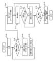
- 1 is a flowchart illustrating an example of an operation of a wireless communication system according to an embodiment.
- 1 is a graph illustrating an example of an improvement in throughput of a wireless communication system according to an embodiment;
- FIG. 2 is a diagram illustrating a hardware configuration of a control device according to an embodiment.
- 1A is a diagram showing a state in which a wireless terminal selects and associates with a base station that detects the strongest signal strength
- FIG. 1B is a diagram showing a state in which a wireless terminal selects and associates with a base station based on wireless communication capability and distance.
- FIG. 6 is a diagram showing the association of a wireless terminal with a base station in an environment where wireless terminals and base stations compatible with MLO coexist with wireless terminals and base stations incompatible with MLO.
- FIG. 6(a) is a diagram showing a state in which a wireless terminal selects and associates with the base station that detects the strongest signal strength.
- FIG. 6(b) is a diagram showing a state in which a wireless terminal selects and associates with a base station based on wireless communication capabilities and distance.
- the base station 10 is assumed to be a base station that does not support MLO and performs wireless communication using only radio waves in the 2 GHz band, for example.
- the wireless terminal 100 is assumed to be a wireless terminal that does not support MLO and performs wireless communication using only radio waves in the 2 GHz band, for example.
- the base station 20 is a base station that supports MLO and performs wireless communication using radio waves in the 2 GHz and 5 GHz bands, for example.
- the wireless terminal 200 is a wireless terminal that supports MLO and performs wireless communication using radio waves in the 2 GHz and 5 GHz bands, for example.
- the frequency band of the radio waves used by the base station 20 and the wireless terminal 200 may be 920 MHz or 6 GHz, or may be 28 GHz or 60 GHz (millimeter waves).
- base stations 10 and the like that do not support MLO will be referred to simply as base stations, and base stations 20 and the like that support MLO will be referred to as MLD base stations to distinguish between them.
- wireless terminals 100 and the like that do not support MLO will be referred to simply as wireless terminals, and wireless terminals 200 and the like that support MLO will be referred to as MLD wireless terminals to distinguish between them.
- base station 10 when there is no distinction between base station 10 and base station 20, the base station is referred to as an AP (Access Point), and when there is no distinction between wireless terminal 100 and wireless terminal 200, the wireless terminal is referred to as a STA (Station).
- AP Access Point
- STA Selection
- the wireless terminal 100 may select base station 20, which is an AP with the highest RSSI and is a short distance from the AP, as its destination.
- the wireless terminal 200 which is an MLD wireless terminal, may connect to base station 10, which is an AP with the highest RSSI and does not support MLO, and is a short distance from the AP.
- the wireless terminal 200 which is an MLD wireless terminal, and base station 20, which is an MLD base station, cannot maximize the functionality (capability) of MLO.
- the base station 10 may not accommodate either the wireless terminal 100 or the wireless terminal 200, and both the wireless terminal 100 and the wireless terminal 200 may select the base station 20 as their destination depending on the distance to the AP and the wireless communication capability.
- the wireless terminal 100, the wireless terminal 200, and the base station 20 cannot maximize the MLO function (capability), and the entire network cannot be optimized.
- FIG. 1 is a diagram showing an example of the configuration of a wireless communication system 1 according to one embodiment.
- the wireless communication system 1 includes, for example, one or more MLD base stations 21, one or more base stations 11, and a control device (attribution determination device) 30.
- base station 11 is a base station that does not support MLO, which performs wireless communication using only radio waves in the 2 GHz band, for example.
- wireless terminal 101 is a wireless terminal that does not support MLO, which performs wireless communication using only radio waves in the 2 GHz band, for example.
- the MLD base station 21 is a base station that supports MLO and performs wireless communication using radio waves in the 2 GHz and 5 GHz bands, for example.
- the MLD wireless terminal 201 is a wireless terminal that supports MLO and performs wireless communication using radio waves in the 2 GHz and 5 GHz bands, for example.
- the base station 11 when there is no distinction between the base station 11 and the MLD base station 21, the base station is referred to as an AP (Access Point), and when there is no distinction between the wireless terminal 101 and the MLD wireless terminal 201, the wireless terminal is referred to as a STA (Station).
- AP Access Point
- STA Selection
- the control device (attribution determination device) 30 controls each of the MLD base station 21 and the base station 11.
- the control device 30 is connected to the network 400, and collects spec information (capability information indicating wireless communication capabilities) and link operation information from the base station 11 and the MLD base station 21, and notifies the base station 11 and the MLD base station 21 of information indicating the AP to which the wireless terminal 101 and the MLD wireless terminal 201 should belong (attribution information).
- FIG. 2 is a functional block diagram illustrating the functions of the control device 30 according to one embodiment.
- the control device 30 has, for example, a communication unit 300, a collection unit 302, a tentative allocation unit 304, an estimation unit 306, a reallocation unit 308, and a processing unit 310.
- the communication unit 300 has a function of performing two-way communication with, for example, the base station 11 and the MLD base station 21.
- the communication unit 300 may also have a function of performing communication via the network 400.
- the collection unit 302 collects capability information indicating the wireless communication capabilities (device specifications) of the MLD wireless terminal 201, the MLD base station 21, the wireless terminal 101, and the base station 11 via the communication unit 300, and outputs the information to the estimation unit 306.
- the capability information (specification information) of each AP and STA is exchanged via beacons, association requests, association responses, etc., and is as follows:
- Capability information ⁇ MLO support, maximum bandwidth, maximum number of streams, maximum number of aggregates, etc. ⁇
- the maximum performance of STA-i is min(STA-i's capabilities, AP-j's capabilities). Note that since the specification information is immutable, once it has been collected it does not need to be collected again.
- the collection unit 302 may also collect link information (link operation information) indicating the connection status of each of the MLD wireless terminals 201 and 101 to the MLD base station 21 or base station 11, and output the information to the estimation unit 306.
- link information link operation information
- the provisional allocation unit 304 provisionally allocates the destination to each of the MLD wireless terminal 201 and the wireless terminal 101 via the communication unit 300, the MLD base station 21, and the base station 11 so that the wireless terminals are accommodated by either the MLD base station 21 or the base station 11.
- the provisional allocation unit 304 then outputs the provisionally allocated destination to the estimation unit 306.
- the estimation unit 306 estimates the throughput of each of the MLD wireless terminal 201 and the wireless terminal 101 based on the capability information collected by the collection unit 302 and the destination provisionally assigned by the provisional assignment unit 304, and outputs each estimated throughput to the provisional reallocation unit 308.
- the estimation unit 306 may also estimate the throughput of each of the MLD wireless terminals 201 and 101 based on link information indicating the connection status of each of the MLD wireless terminals 201 and 101 to the MLD base station 21 or base station 11.
- the reallocation unit 308 reallocates the destination to the MLD wireless terminal 201 or wireless terminal 101 whose throughput estimated by the estimation unit 306 is less than a predetermined threshold.
- the reallocation unit 308 then outputs the reallocated destination to the processing unit 310.
- the processing unit 310 When the throughput of each of the MLD wireless terminal 201 and the wireless terminal 101 satisfies a predetermined condition due to the destination re-allocated by the reallocation unit 308, the processing unit 310 performs a process of determining the destination re-allocated by the reallocation unit 308 as the final destination, and outputs the processing result to the MLD base station 21 and the base station 11 via the communication unit 300.
- control device 30 has the function of determining the AP to which each of the MLD wireless terminal 201 and the wireless terminal 101 belongs. More specifically, the control device 30 determines the AP to which each of the MLD wireless terminal 201 and the wireless terminal 101 belongs as follows (A) to (C).
- the control device 30 determines the destination of each of the MLD wireless terminal 201 and the wireless terminal 101 so as to maximize the throughput of the STAs under each AP for which the destination is to be derived (maximizing the number of STAs for which the throughput is minimized).
- the control device 30 determines the destination of each of the MLD wireless terminals 201 and 101 so as to maximize throughput according to their wireless communication capabilities (optimizing to obtain greater throughput for a STA with two links compared to a STA with one link).
- the control device 30 maximizes the throughput of a specific link (for example, determines the destination so that the throughput of a 5 GHz link is maximized).
- Figure 3 is a flowchart showing an example of the operation of the wireless communication system 1 according to one embodiment.
- step 100 the wireless communication system 1 has the control device 30 collect capability information and link information for each AP and each STA.
- step 102 the control device 30 determines whether or not there is an STA whose home address has not been determined. If there is an STA whose home address has not been determined (S102: Yes), the control device 30 proceeds to processing of S104. If there is no STA whose home address has not been determined (S102: No), the control device 30 proceeds to processing of S108.
- step 104 the control device 30 selects one STA whose home destination has not yet been determined.
- step 106 the control device 30 provisionally assigns one AP from among all APs to which the selected STA can belong, and returns to the process of S102.
- step 108 the control device 30 estimates the throughput of each STA. Specifically, the control device 30 estimates the throughput of each STA based on at least one of the capability information of the AP and each STA and the link information.
- step 110 the control device 30 selects, for example, one STA whose throughput is less than a predetermined threshold, and performs provisional reassignment of an AP to that STA.
- step 112 the control device 30 determines whether or not there is a predetermined throughput improvement. If it determines that there is an improvement in throughput (S112: Yes), the control device 30 proceeds to processing of S116. If it determines that there is no improvement in throughput (S112: No), the control device 30 proceeds to processing of S114.
- control device 30 determines whether the throughput of STAs with a certain percentage of low throughput (bottom X% of STAs) among all STAs after the provisional reallocation has improved.
- step 114 the control device 30 returns the STA that has undergone reallocation to the AP that it was in before the reallocation.
- step 116 the control device 30 determines whether or not the termination condition for the process of improving the throughput has been met. If it is determined that the termination condition has been met (S116: Yes), the control device 30 proceeds to processing of S118, and if it is determined that the termination condition has not been met (S116: No), the control device 30 returns to processing of S110.
- the termination condition may be, for example, the number of times the process is performed reaches a predetermined value, the rate of improvement in throughput falls below a threshold, or the estimated throughput of all STAs reaches the maximum value of the capabilities of the device itself.
- step 118 the control device 30 determines the current home destination of each STA and notifies each STA of the result of the determination via the AP.
- FIG. 4 is a graph illustrating the results of throughput improvement achieved by the wireless communication system 1 according to one embodiment.
- the results are shown for a case where 10 wireless terminals capable of using two links and 10 wireless terminals capable of using only one link are mixed in an evaluation area of 100 (m) x 100 (m).
- the results of throughput improvement achieved by the wireless communication system 1 are shown as Proposed.
- the wireless communication system 1 can improve throughput more than when the STA is randomly assigned to an AP and more than when the STA is assigned to the AP with the highest RSSI.
- each function of the control device 30 may be configured in whole or in part by hardware such as a PLD (Programmable Logic Device) or an FPGA (Field Programmable Gate Array), or may be configured as a program executed by a processor such as a CPU.
- hardware such as a PLD (Programmable Logic Device) or an FPGA (Field Programmable Gate Array)
- control device 30 can be realized using a computer and a program, and the program can be recorded on a storage medium or provided via a network.
- FIG. 5 is a diagram illustrating an example of the hardware configuration of the control device 30 according to one embodiment.
- the control device 30 has an input unit 50, an output unit 51, a communication unit 52, a CPU 53, a memory 54, and a HDD 55 connected via a bus 56, and has the functions of a computer.
- the control device 30 is also capable of inputting and outputting data to and from a computer-readable storage medium 57.
- the input unit 50 is, for example, a keyboard and a mouse.
- the output unit 51 is, for example, a display device such as a display.
- the communication unit 52 corresponds to, for example, the communication unit 300 described above, and is a communication interface that communicates with other devices.
- the CPU 53 controls each component of the control device 30 and performs predetermined processing.
- the memory 54 and HDD 55 store data, etc.
- the storage medium 57 is capable of storing programs and the like that cause the control device 30 to execute the functions of the control device 30. Note that the architecture that constitutes the control device 30 is not limited to the example shown in FIG. 5.
Landscapes
- Engineering & Computer Science (AREA)
- Computer Networks & Wireless Communication (AREA)
- Signal Processing (AREA)
- Databases & Information Systems (AREA)
- Mobile Radio Communication Systems (AREA)
Abstract
一実施形態にかかる無線通信システムは、MLD無線端末、MLD基地局、無線端末、及び基地局それぞれのケーパビリティ情報を収集する収集部と、MLD無線端末及び無線端末それぞれに対し、MLD基地局及び基地局のいずれかが収容するように帰属先を仮割当する仮割当部と、ケーパビリティ情報、及び仮割当した帰属先に基づいて、MLD無線端末及び無線端末それぞれのスループットを推定する推定部と、推定したスループットが所定の閾値未満であるMLD無線端末又は無線端末に対し、帰属先を再仮割当する再仮割当部と、再仮割当した帰属先により、MLD無線端末及び無線端末それぞれのスループットが所定条件を満たしたときに、最終的な帰属先を決定する処理を行う処理部とを有する。
Description
本発明は、無線通信システム、制御装置、無線通信方法及び無線通信プログラムに関する。
例えば、IEEE802.11be規格では、周波数チャネルの異なる複数の伝送路を活用してフレーム伝送を行うマルチリンク伝送(MLO:Multi-Link Operation)が規定される予定である(例えば、非特許文献1,2参照)。
MLOでは、1つの装置に異なる複数の無線インターフェースを搭載し、複数の伝送路を確立する機能が採用されており、このような装置はマルチリンクデバイス(MLD)と呼ばれる。
マルチリンク伝送は、例えば1つの筐体に複数の基地局機能を搭載するMLD AP(AP:Access Point)と、1つの筐体に複数の無線端末を搭載するMLD STA(STA:Station)との間でそれぞれリンクを形成する無線通信である。
したがって、マルチリンク伝送では、複数の伝送路を活用して異なるフレーム送信を行うことにより、スループットの向上や遅延時間の低減等が期待されている。
一方、IEEE802.11規格では、無線端末をどの基地局に帰属させるかを決定する方法(帰属先の決定)については規定されていない。例えば無線端末が複数の基地局に接続可能である環境において、無線端末が帰属先となる基地局を選択する方法は、ベンダーそれぞれの実装に任されている。
例えば、無線端末の帰属先となる基地局を選択する方法としては、以下の4つの方法が一般的である。
1)無線端末が最初に検出した基地局を選択する。
2)最も信号強度を高く検出された基地局を選択する。
3)すでに帰属している無線端末の台数が最も少ない基地局を選択する。
4)検出された複数の基地局の中から無作為に基地局を選択する。
2)最も信号強度を高く検出された基地局を選択する。
3)すでに帰属している無線端末の台数が最も少ない基地局を選択する。
4)検出された複数の基地局の中から無作為に基地局を選択する。
IEEE Standard for Information Technology-Telecommunications and Information Exchange between Systems Local and Metropolitan Area Networks-Specific Requirements, Part 11: Wireless LAN Medium Access Control(MAC) and Physical Layer (PHY) Specifications, IEEE Std 802.11TM‐2020, (Revision of IEEE Std 802.11‐2016), P.255-256, P.1672-1678
IEEE P802.11beTM D3.0, Draft Standard for Information technology- Telecommunications and information exchange between systems Local and metropolitan area networks- Specific requirements, Part 11: Wireless LAN Medium Access Control(MAC) and Physical Layer (PHY) Specifications, Amendment 8: Enhancements for extremely high throughput (EHT), IEEE P802.11beTM/D3.0, January 2023, (amendment to IEEE P802.11-REVme/TM1.3), P.479-586
従来、MLOに対応する無線端末及び基地局と、MLOに非対応の無線端末及び基地局とが混在する環境においては、MLOに対応する無線端末が、MLOに非対応の基地局を帰属先として選択してしまうと、MLO機能を効果的に使用できないことがあった。
本発明は、MLOに対応する無線端末及び基地局と、MLOに非対応の無線端末及び基地局とが混在する環境においても、スループットの向上を可能にすることができる無線通信システム、制御装置、無線通信方法及び無線通信プログラムを提供することを目的とする。
本発明の一実施形態にかかる無線通信システムは、MLOに対応するMLD無線端末、及びMLOに非対応の無線端末を収容可能な1台以上のMLD基地局と、MLOに非対応の無線端末のみを収容可能な1台以上の基地局と、前記MLD基地局及び前記基地局それぞれを制御する制御装置とを備えた無線通信システムにおいて、前記制御装置が、前記MLD無線端末、前記MLD基地局、前記無線端末、及び前記基地局それぞれの無線通信能力を示すケーパビリティ情報を収集する収集部と、前記MLD無線端末及び前記無線端末それぞれに対し、前記MLD基地局及び前記基地局のいずれかが収容するように帰属先を仮割当する仮割当部と、前記収集部が収集したケーパビリティ情報、及び前記仮割当部が仮割当した帰属先に基づいて、前記MLD無線端末及び前記無線端末それぞれのスループットを推定する推定部と、前記推定部が推定したスループットが所定の閾値未満である前記MLD無線端末又は前記無線端末に対し、帰属先を再仮割当する再仮割当部と、前記再仮割当部が再仮割当した帰属先により、前記MLD無線端末及び前記無線端末それぞれのスループットが所定条件を満たしたときに、前記再仮割当部が再仮割当した帰属先を最終的な帰属先として決定する処理を行う処理部とを有することを特徴とする。
また、本発明の一実施形態にかかる制御装置は、MLOに対応するMLD無線端末、及びMLOに非対応の無線端末を収容可能な1台以上のMLD基地局と、MLOに非対応の無線端末のみを収容可能な1台以上の基地局とを制御する制御装置において、前記MLD無線端末、前記MLD基地局、前記無線端末、及び前記基地局それぞれの無線通信能力を示すケーパビリティ情報を収集する収集部と、前記MLD無線端末及び前記無線端末それぞれに対し、前記MLD基地局及び前記基地局のいずれかが収容するように帰属先を仮割当する仮割当部と、前記収集部が収集したケーパビリティ情報、及び前記仮割当部が仮割当した帰属先に基づいて、前記MLD無線端末及び前記無線端末それぞれのスループットを推定する推定部と、前記推定部が推定したスループットが所定の閾値未満である前記MLD無線端末又は前記無線端末に対し、帰属先を再仮割当する再仮割当部と、前記再仮割当部が再仮割当した帰属先により、前記MLD無線端末及び前記無線端末それぞれのスループットが所定条件を満たしたときに、前記再仮割当部が再仮割当した帰属先を最終的な帰属先として決定する処理を行う処理部とを有することを特徴とする。
また、本発明の一実施形態にかかる無線通信方法は、MLOに対応するMLD無線端末、及びMLOに非対応の無線端末を収容可能な1台以上のMLD基地局と、MLOに非対応の無線端末のみを収容可能な1台以上の基地局とを制御装置が制御する無線通信方法において、前記MLD無線端末、前記MLD基地局、前記無線端末、及び前記基地局それぞれの無線通信能力を示すケーパビリティ情報を収集する収集工程と、前記MLD無線端末及び前記無線端末それぞれに対し、前記MLD基地局及び前記基地局のいずれかが収容するように帰属先を仮割当する仮割当工程と、前記収集工程により収集したケーパビリティ情報、及び前記仮割当工程により仮割当した帰属先に基づいて、前記MLD無線端末及び前記無線端末それぞれのスループットを推定する推定工程と、前記推定工程により推定したスループットが所定の閾値未満である前記MLD無線端末又は前記無線端末に対し、帰属先を再仮割当する再仮割当工程と、前記再仮割当工程により再仮割当した帰属先により、前記MLD無線端末及び前記無線端末それぞれのスループットが所定条件を満たしたときに、前記再仮割当工程により再仮割当した帰属先を最終的な帰属先として決定する処理を行う処理工程とを含むことを特徴とする。
本発明によれば、MLOに対応する無線端末及び基地局と、MLOに非対応の無線端末及び基地局とが混在する環境においても、スループットの向上を可能にすることができる。
まず、本発明がなされるに至った背景について説明する。図6は、MLOに対応する無線端末及び基地局と、MLOに非対応の無線端末及び基地局とが混在する環境における無線端末の基地局に対する帰属を模式的に示す図である。図6(a)は、無線端末が最も強い信号強度を検出した基地局を選択して帰属した状態を模式的に示す図である。図6(b)は、無線端末が無線通信能力と距離に基づいて基地局を選択して帰属した状態を模式的に示す図である。
ここで、基地局10は、例えば2GHz帯の電波のみを用いて無線通信を行うMLOに非対応の基地局であるとする。また、無線端末100は、例えば2GHz帯の電波のみを用いて無線通信を行うMLOに非対応の無線端末であるとする。
また、基地局20は、例えば2GHz帯及び5GHz帯の電波を用いて無線通信を行うMLOに対応する基地局であるとする。また、無線端末200は、例えば2GHz帯及び5GHz帯の電波を用いて無線通信を行うMLOに対応する無線端末であるとする。なお、基地局20及び無線端末200が用いる電波の周波数帯は、920MHzや6GHzであってもよいし、28GHzや60GHz(ミリ波)であってもよい。
以下、MLOに非対応の基地局10などを単に基地局と称し、MLOに対応する基地局20などをMLD基地局と称して区別する。また、MLOに非対応の無線端末100などを単に無線端末と称し、MLOに対応する無線端末200などをMLD無線端末と称して区別する。
また、基地局10と基地局20とを区別しない場合には、基地局をAP(Access Point)と記し、無線端末100と無線端末200とを区別しない場合には、無線端末をSTA(Station)と記す。
図6(a)に示したように、例えば無線端末100は、APまでの距離が短く、RSSIが最も大きいAPである基地局20を帰属先として選択することがある。また、MLD無線端末である無線端末200は、APまでの距離が短く、RSSIが最も大きいAPであるMLOに非対応の基地局10に接続することがある。この場合、MLD無線端末である無線端末200、及びMLD基地局である基地局20は、MLOの機能(能力)を最大限に発揮することができない。
また、図6(b)に示したように、基地局10は、無線端末100及び無線端末200のいずれも収容せず、無線端末100及び無線端末200のいずれもが、APまでの距離及び無線通信能力に応じて基地局20を帰属先として選択することがある。この場合、無線端末100、無線端末200、及び基地局20は、MLOの機能(能力)を最大限に発揮することができず、ネットワーク全体の最適化もできない。
次に、一実施形態にかかる無線通信システム1について説明する。図1は、一実施形態にかかる無線通信システム1の構成例を示す図である。
図1に示すように、無線通信システム1は、例えば1台以上のMLD基地局21と、1台以上の基地局11と、制御装置(帰属先決定装置)30とを有する。
ここで、基地局11は、例えば2GHz帯の電波のみを用いて無線通信を行うMLOに非対応の基地局であるとする。また、無線端末101は、例えば2GHz帯の電波のみを用いて無線通信を行うMLOに非対応の無線端末であるとする。
また、MLD基地局21は、例えば2GHz帯及び5GHz帯の電波を用いて無線通信を行うMLOに対応する基地局であるとする。また、MLD無線端末201は、例えば2GHz帯及び5GHz帯の電波を用いて無線通信を行うMLOに対応する無線端末であるとする。
また、基地局11とMLD基地局21とを区別しない場合には、基地局をAP(Access Point)と記し、無線端末101とMLD無線端末201とを区別しない場合には、無線端末をSTA(Station)と記す。
制御装置(帰属先決定装置)30は、MLD基地局21及び基地局11それぞれを制御する。例えば、制御装置30は、例えばネットワーク400に接続されており、基地局11及びMLD基地局21からスペック情報(無線通信能力を示すケーパビリティ情報)及びリンクの運用情報などを収集し、無線端末101及びMLD無線端末201が帰属すべきAPを示す情報(帰属先情報)を基地局11及びMLD基地局21に対して通知する。
図2は、一実施形態にかかる制御装置30が有する機能を例示する機能ブロック図である。図2に示すように、制御装置30は、例えば通信部300、収集部302、仮割当部304、推定部306、再仮割当部308、及び処理部310を有する。
通信部300は、例えば基地局11及びMLD基地局21それぞれと双方向通信を行う機能を有する。また、通信部300は、ネットワーク400を介して通信を行う機能を有していてもよい。
収集部302は、通信部300を介して、MLD無線端末201、MLD基地局21、無線端末101、及び基地局11それぞれの無線通信能力(機器スペック)を示すケーパビリティ情報を収集し、推定部306に対して出力する。
AP及びSTAそれぞれのケーパビリティ情報(スペック情報)は、Beacon, Association request, Association responseなどで交換される以下のような情報である。
ケーパビリティ情報={MLO対応の可否、最大帯域幅、最大ストリーム数、最大アグリゲート数など}
例えば、STA-iがAP-jに帰属した場合に、STA-iの最大性能は、min(STA-iのケーパビリティ,AP-jのケーパビリティ)となる。なお、スペック情報は、不変であるため、一度収集されると再収集は不要である。
また、収集部302は、MLD基地局21又は基地局11に対するMLD無線端末201及び無線端末101それぞれの接続状況を示すリンク情報(リンクの運用情報)を収集し、推定部306に対して出力してもよい。
リンク情報には、例えば、各AP及びSTA間の信号強度により推定されるMCS(Modulation Coding Scheme)情報、APがすでに収容しているSTA台数、収容トラヒック情報、トラヒックの方向(上り・下り)、トラヒックの優先度(高優先、又は低優先)、リンクの他STAによるエアータイム占有度合い、及び再送率などが含まれる。なお、リンク情報は、無線通信システム1の運用状態に応じて変化するため、定期的に収集することが必要となる。
仮割当部304は、通信部300、MLD基地局21及び基地局11を介して、MLD無線端末201及び無線端末101それぞれに対し、MLD基地局21及び基地局11のいずれかが収容するように帰属先を仮割当する。そして、仮割当部304は、仮割当した帰属先を推定部306に対して出力する。
推定部306は、収集部302が収集したケーパビリティ情報、及び仮割当部304が仮割当した帰属先に基づいて、MLD無線端末201及び無線端末101それぞれのスループットを推定し、推定したスループットそれぞれを再仮割当部308に対して出力する。
また、推定部306は、MLD基地局21又は基地局11に対するMLD無線端末201及び無線端末101それぞれの接続状況を示すリンク情報に基づいて、MLD無線端末201及び無線端末101それぞれのスループットを推定してもよい。
再仮割当部308は、推定部306が推定したスループットが所定の閾値未満であるMLD無線端末201又は無線端末101に対し、帰属先を再仮割当する。そして、再仮割当部308は、再仮割当した帰属先を処理部310に対して出力する。
処理部310は、再仮割当部308が再仮割当した帰属先により、MLD無線端末201及び無線端末101それぞれのスループットが所定条件を満たしたときに、再仮割当部308が再仮割当した帰属先を最終的な帰属先として決定する処理を行い、通信部300を介して処理結果をMLD基地局21及び基地局11に対して出力する。
このように、制御装置30は、MLD無線端末201及び無線端末101それぞれの帰属先となるAPを決定する機能を有する。より具体的には、制御装置30は、以下の(A)~(C)のようにMLD無線端末201及び無線端末101それぞれの帰属先を決定する。
(A)制御装置30は、帰属先を導出する対象となる各AP配下のSTAのスループットを最大化させるようにMLD無線端末201及び無線端末101それぞれの帰属先を決定する(スループットが最小となるSTA数を最大化する)。
(B)制御装置30は、無線通信能力に応じてスループットを最大化させるようにMLD無線端末201及び無線端末101それぞれの帰属先を決定する(1リンクを有するSTAに比べて2リンクを有するSTAには、より大きなスループットが得られるように最適化する)。
(C)制御装置30は、特定のリンクのスループットを最大化する(例えば、5GHzのリンクのスループットが最大になるように帰属先を決定する)。
(B)制御装置30は、無線通信能力に応じてスループットを最大化させるようにMLD無線端末201及び無線端末101それぞれの帰属先を決定する(1リンクを有するSTAに比べて2リンクを有するSTAには、より大きなスループットが得られるように最適化する)。
(C)制御装置30は、特定のリンクのスループットを最大化する(例えば、5GHzのリンクのスループットが最大になるように帰属先を決定する)。
次に、無線通信システム1の動作例について説明する。図3は、一実施形態にかかる無線通信システム1の動作例を示すフローチャートである。
図3に示すように、ステップ100(S100)において、無線通信システム1は、制御装置30が各AP及び各STAのケーパビリティ情報及びリンク情報を収集する。
ステップ102(S102)において、制御装置30は、帰属先未定のSTAがあるか否かを判定し、帰属先未定のSTAがある場合(S102:Yes)にはS104の処理に進み、帰属先未定のSTAがない場合(S102:No)にはS108の処理に進む。
ステップ104(S104)において、制御装置30は、帰属先未定のSTAを1台選択する。
ステップ106(S106)において、制御装置30は、選択したSTAに対し、帰属可能な全てのAPの中の1台のAPを仮割当し、S102の処理に戻る。
ステップ108(S108)において、制御装置30は、各STAのスループットを推定する。具体的には、制御装置30は、AP及びSTAそれぞれのケーパビリティ情報、及びリンク情報の少なくともいずれかに基づいて各STAのスループットを推定する。
ステップ110(S110)において、制御装置30は、例えばスループットが所定の閾値未満である1台のSTAを選択し、当該STAに対するAPの再仮割当を実施する。
ステップ112(S112)において、制御装置30は、所定のスループット改善の有無を判定し、スループット改善があると判定した場合(S112:Yes)にはS116の処理に進み、スループット改善がないと判定した場合(S112:No)にはS114の処理に進む。
例えば、制御装置30は、再仮割当を行った後の全STAの中で所定割合のスループットが小さいSTA(下位X%のSTA)のスループットが改善したか否かを判定する。
ステップ114(S114)において、制御装置30は、再仮割当を行ったSTAの帰属先を再仮割当前のAPに戻す。
ステップ116(S116)において、制御装置30は、スループットを向上させる処理に対する終了条件を満たしたか否かを判定し、満たしていると判定した場合(S116:Yes)にはS118の処理に進み、満たしていないと判定した場合(S116:No)にはS110の処理に戻る。
ここで、終了条件は、例えば処理の実施回数が所定値に達すること、スループットの改善速度が閾値以下になること、又は、全STAの推定スループットが自装置のケーパビリティの最大値になることなどであるとする。
ステップ118(S118)において、制御装置30は、各STAの帰属先を現時点の帰属先として決定し、APを介して各STAへ決定した結果を通知する。
図4は、一実施形態にかかる無線通信システム1がスループットを改善させた結果を例示するグラフである。ここでは、100(m)×100(m)の評価エリアに、2リンク使用可能な無線端末と、1リンクしか使用できない無線端末とをそれぞれ10台ずつ混在させた場合の結果が示されている。なお、無線通信システム1がスループットを改善させた結果は、Proposedとして示されている。
このように、一実施形態にかかる無線通信システム1は、MLOに対応する無線端末及び基地局と、MLOに非対応の無線端末及び基地局とが混在する環境において、STAを無作為にAPへ帰属させる場合よりも、STAを最大RSSIのAPへ帰属させる場合よりも、スループットを改善させることができる。
なお、制御装置30が有する各機能は、それぞれ一部又は全部がPLD(Programmable Logic Device)やFPGA(Field Programmable Gate Array)等のハードウェアによって構成されてもよいし、CPU等のプロセッサが実行するプログラムとして構成されてもよい。
例えば、制御装置30は、コンピュータとプログラムを用いて実現することができ、プログラムを記憶媒体に記録することも、ネットワークを通して提供することも可能である。
図5は、一実施形態にかかる制御装置30が有するハードウェア構成を例示する図である。図5に示すように、制御装置30は、入力部50、出力部51、通信部52、CPU53、メモリ54及びHDD55がバス56を介して接続され、コンピュータとしての機能を備える。また、制御装置30は、コンピュータ読み取り可能な記憶媒体57との間でデータを入出力することができるようにされている。
入力部50は、例えばキーボード及びマウス等である。出力部51は、例えばディスプレイなどの表示装置である。
通信部52は、例えば上述した通信部300に対応し、他の装置との間で通信を行う通信インターフェースである。
CPU53は、制御装置30を構成する各部を制御し、所定の処理等を行う。メモリ54及びHDD55は、データ等を記憶する。
記憶媒体57は、制御装置30が有する機能を実行させるプログラム等を記憶可能にされている。なお、制御装置30を構成するアーキテクチャは図5に示した例に限定されない。
1・・・無線通信システム、11・・・基地局、21・・・MLD基地局、30・・・制御装置、50・・・入力部、51・・・出力部、52・・・通信部、53・・・CPU、54・・・メモリ、55・・・HDD、56・・・バス、57・・・記憶媒体、101・・・無線端末、201・・・MLD無線端末、300・・・通信部、302・・・収集部、304・・・仮割当部、306・・・推定部、308・・・再仮割当部、310・・・処理部、400・・・ネットワーク
Claims (7)
- MLOに対応するMLD無線端末、及びMLOに非対応の無線端末を収容可能な1台以上のMLD基地局と、
MLOに非対応の無線端末のみを収容可能な1台以上の基地局と、
前記MLD基地局及び前記基地局それぞれを制御する制御装置と
を備えた無線通信システムにおいて、
前記制御装置は、
前記MLD無線端末、前記MLD基地局、前記無線端末、及び前記基地局それぞれの無線通信能力を示すケーパビリティ情報を収集する収集部と、
前記MLD無線端末及び前記無線端末それぞれに対し、前記MLD基地局及び前記基地局のいずれかが収容するように帰属先を仮割当する仮割当部と、
前記収集部が収集したケーパビリティ情報、及び前記仮割当部が仮割当した帰属先に基づいて、前記MLD無線端末及び前記無線端末それぞれのスループットを推定する推定部と、
前記推定部が推定したスループットが所定の閾値未満である前記MLD無線端末又は前記無線端末に対し、帰属先を再仮割当する再仮割当部と、
前記再仮割当部が再仮割当した帰属先により、前記MLD無線端末及び前記無線端末それぞれのスループットが所定条件を満たしたときに、前記再仮割当部が再仮割当した帰属先を最終的な帰属先として決定する処理を行う処理部と
を有することを特徴とする無線通信システム。 - 前記推定部は、
前記MLD基地局又は前記基地局に対する前記MLD無線端末及び前記無線端末それぞれの接続状況を示すリンク情報に基づいて、前記MLD無線端末及び前記無線端末それぞれのスループットを推定すること
を特徴とする請求項1に記載の無線通信システム。 - MLOに対応するMLD無線端末、及びMLOに非対応の無線端末を収容可能な1台以上のMLD基地局と、MLOに非対応の無線端末のみを収容可能な1台以上の基地局とを制御する制御装置において、
前記MLD無線端末、前記MLD基地局、前記無線端末、及び前記基地局それぞれの無線通信能力を示すケーパビリティ情報を収集する収集部と、
前記MLD無線端末及び前記無線端末それぞれに対し、前記MLD基地局及び前記基地局のいずれかが収容するように帰属先を仮割当する仮割当部と、
前記収集部が収集したケーパビリティ情報、及び前記仮割当部が仮割当した帰属先に基づいて、前記MLD無線端末及び前記無線端末それぞれのスループットを推定する推定部と、
前記推定部が推定したスループットが所定の閾値未満である前記MLD無線端末又は前記無線端末に対し、帰属先を再仮割当する再仮割当部と、
前記再仮割当部が再仮割当した帰属先により、前記MLD無線端末及び前記無線端末それぞれのスループットが所定条件を満たしたときに、前記再仮割当部が再仮割当した帰属先を最終的な帰属先として決定する処理を行う処理部と
を有することを特徴とする制御装置。 - 前記推定部は、
前記MLD基地局又は前記基地局に対する前記MLD無線端末及び前記無線端末それぞれの接続状況を示すリンク情報に基づいて、前記MLD無線端末及び前記無線端末それぞれのスループットを推定すること
を特徴とする請求項3に記載の制御装置。 - MLOに対応するMLD無線端末、及びMLOに非対応の無線端末を収容可能な1台以上のMLD基地局と、MLOに非対応の無線端末のみを収容可能な1台以上の基地局とを制御装置が制御する無線通信方法において、
前記MLD無線端末、前記MLD基地局、前記無線端末、及び前記基地局それぞれの無線通信能力を示すケーパビリティ情報を収集する収集工程と、
前記MLD無線端末及び前記無線端末それぞれに対し、前記MLD基地局及び前記基地局のいずれかが収容するように帰属先を仮割当する仮割当工程と、
前記収集工程により収集したケーパビリティ情報、及び前記仮割当工程により仮割当した帰属先に基づいて、前記MLD無線端末及び前記無線端末それぞれのスループットを推定する推定工程と、
前記推定工程により推定したスループットが所定の閾値未満である前記MLD無線端末又は前記無線端末に対し、帰属先を再仮割当する再仮割当工程と、
前記再仮割当工程により再仮割当した帰属先により、前記MLD無線端末及び前記無線端末それぞれのスループットが所定条件を満たしたときに、前記再仮割当工程により再仮割当した帰属先を最終的な帰属先として決定する処理を行う処理工程と
を含むことを特徴とする無線通信方法。 - 前記推定工程では、
前記MLD基地局又は前記基地局に対する前記MLD無線端末及び前記無線端末それぞれの接続状況を示すリンク情報に基づいて、前記MLD無線端末及び前記無線端末それぞれのスループットを推定すること
を特徴とする請求項5に記載の無線通信方法。 - 請求項3又は4に記載の制御装置の各部としてコンピュータを機能させるための無線通信プログラム。
Priority Applications (2)
| Application Number | Priority Date | Filing Date | Title |
|---|---|---|---|
| PCT/JP2023/022298 WO2024257313A1 (ja) | 2023-06-15 | 2023-06-15 | 無線通信システム、制御装置、無線通信方法及び無線通信プログラム |
| JP2025527165A JPWO2024257313A1 (ja) | 2023-06-15 | 2023-06-15 |
Applications Claiming Priority (1)
| Application Number | Priority Date | Filing Date | Title |
|---|---|---|---|
| PCT/JP2023/022298 WO2024257313A1 (ja) | 2023-06-15 | 2023-06-15 | 無線通信システム、制御装置、無線通信方法及び無線通信プログラム |
Publications (1)
| Publication Number | Publication Date |
|---|---|
| WO2024257313A1 true WO2024257313A1 (ja) | 2024-12-19 |
Family
ID=93851689
Family Applications (1)
| Application Number | Title | Priority Date | Filing Date |
|---|---|---|---|
| PCT/JP2023/022298 Ceased WO2024257313A1 (ja) | 2023-06-15 | 2023-06-15 | 無線通信システム、制御装置、無線通信方法及び無線通信プログラム |
Country Status (2)
| Country | Link |
|---|---|
| JP (1) | JPWO2024257313A1 (ja) |
| WO (1) | WO2024257313A1 (ja) |
Citations (3)
| Publication number | Priority date | Publication date | Assignee | Title |
|---|---|---|---|---|
| JP2017076860A (ja) * | 2015-10-14 | 2017-04-20 | 西日本電信電話株式会社 | アクセスポイント管理サーバ、アクセスポイント、通信システム、アクセスポイント管理方法、通信制御方法、アクセスポイント管理プログラム及び通信制御プログラム |
| WO2021246203A1 (ja) * | 2020-06-03 | 2021-12-09 | シャープ株式会社 | 無線通信装置 |
| WO2023033184A1 (ja) * | 2021-09-06 | 2023-03-09 | シャープ株式会社 | 通信装置および通信方法 |
-
2023
- 2023-06-15 JP JP2025527165A patent/JPWO2024257313A1/ja active Pending
- 2023-06-15 WO PCT/JP2023/022298 patent/WO2024257313A1/ja not_active Ceased
Patent Citations (3)
| Publication number | Priority date | Publication date | Assignee | Title |
|---|---|---|---|---|
| JP2017076860A (ja) * | 2015-10-14 | 2017-04-20 | 西日本電信電話株式会社 | アクセスポイント管理サーバ、アクセスポイント、通信システム、アクセスポイント管理方法、通信制御方法、アクセスポイント管理プログラム及び通信制御プログラム |
| WO2021246203A1 (ja) * | 2020-06-03 | 2021-12-09 | シャープ株式会社 | 無線通信装置 |
| WO2023033184A1 (ja) * | 2021-09-06 | 2023-03-09 | シャープ株式会社 | 通信装置および通信方法 |
Also Published As
| Publication number | Publication date |
|---|---|
| JPWO2024257313A1 (ja) | 2024-12-19 |
Similar Documents
| Publication | Publication Date | Title |
|---|---|---|
| CN107071782B (zh) | 基于网络切片的无线资源分配方法 | |
| CN112383952B (zh) | 一种载波确定方法及装置 | |
| US10588163B2 (en) | Wireless backhaul connection establishment method and apparatus | |
| CN108391317A (zh) | 一种蜂窝网络中d2d通信的资源分配方法及系统 | |
| EP3051860B1 (en) | Device and method for analyzing network topology in wireless communication system | |
| US20210282141A1 (en) | Methods and apparatus for allocating and/or using partial and bulk spectrum in a network | |
| EP2304899A1 (en) | Priority-based admission control in a network with variable channel data rates | |
| CN113891493A (zh) | 多链路设备的aid分配方法及相关装置 | |
| CN115442857A (zh) | 一种切换方法及装置 | |
| CN118612747A (zh) | 用于无线通信的电子设备和方法、计算机可读存储介质 | |
| WO2024013816A1 (ja) | 無線通信システム、無線通信方法、集中制御装置及び集中制御プログラム | |
| JP2021022913A (ja) | 制御装置、及び、制御方法 | |
| US9094836B2 (en) | Method for calculating fairness index and method for allocating resources based on the fairness index in coexistence management system | |
| CN102333348A (zh) | 基于认知无线电的终端群接入网切换网络侧控制方法 | |
| WO2021015236A1 (ja) | 制御装置、及び、制御方法 | |
| WO2024161599A1 (ja) | 無線通信システム、無線通信方法、制御装置及び集中制御プログラム | |
| WO2024127499A1 (ja) | 無線通信システム、集中制御装置、集中制御方法及び集中制御プログラム | |
| CN104540229A (zh) | 资源管理方法和系统 | |
| CN110753357A (zh) | 一种异构网络中的干扰管理和资源分配方法 | |
| CN113099406B (zh) | 一种室内VLC-WiFi异构网络服务质量感知的跨层资源分配方法 | |
| Lima et al. | Multiobjective planning of wireless local area networks (WLAN) using genetic algorithms | |
| CN112203354B (zh) | 一种业务处理方法及装置 | |
| CN115551049A (zh) | 干扰抑制方法、装置、设备及存储介质 | |
| KR102058728B1 (ko) | 공존 관리 시스템에서 페어니스 인덱스를 산출하는 방법 및 페어니스 인덱스를 기반으로 자원을 할당하는 방법 | |
| JP7340367B2 (ja) | 基地局、及び、通知方法 |
Legal Events
| Date | Code | Title | Description |
|---|---|---|---|
| 121 | Ep: the epo has been informed by wipo that ep was designated in this application |
Ref document number: 23941615 Country of ref document: EP Kind code of ref document: A1 |
|
| ENP | Entry into the national phase |
Ref document number: 2025527165 Country of ref document: JP Kind code of ref document: A |
|
| WWE | Wipo information: entry into national phase |
Ref document number: 2025527165 Country of ref document: JP |
|
| NENP | Non-entry into the national phase |
Ref country code: DE |