WO2024253159A1 - 中空糸膜モジュール - Google Patents
中空糸膜モジュール Download PDFInfo
- Publication number
- WO2024253159A1 WO2024253159A1 PCT/JP2024/020705 JP2024020705W WO2024253159A1 WO 2024253159 A1 WO2024253159 A1 WO 2024253159A1 JP 2024020705 W JP2024020705 W JP 2024020705W WO 2024253159 A1 WO2024253159 A1 WO 2024253159A1
- Authority
- WO
- WIPO (PCT)
- Prior art keywords
- hollow fiber
- fiber membrane
- outer case
- hole
- membrane module
- Prior art date
- Legal status (The legal status is an assumption and is not a legal conclusion. Google has not performed a legal analysis and makes no representation as to the accuracy of the status listed.)
- Ceased
Links
Images


Classifications
-
- B—PERFORMING OPERATIONS; TRANSPORTING
- B01—PHYSICAL OR CHEMICAL PROCESSES OR APPARATUS IN GENERAL
- B01D—SEPARATION
- B01D63/00—Apparatus in general for separation processes using semi-permeable membranes
- B01D63/02—Hollow fibre modules
- B01D63/021—Manufacturing thereof
- B01D63/0231—Manufacturing thereof using supporting structures, e.g. filaments for weaving mats
-
- H—ELECTRICITY
- H01—ELECTRIC ELEMENTS
- H01M—PROCESSES OR MEANS, e.g. BATTERIES, FOR THE DIRECT CONVERSION OF CHEMICAL ENERGY INTO ELECTRICAL ENERGY
- H01M8/00—Fuel cells; Manufacture thereof
- H01M8/04—Auxiliary arrangements, e.g. for control of pressure or for circulation of fluids
- H01M8/04082—Arrangements for control of reactant parameters, e.g. pressure or concentration
- H01M8/04089—Arrangements for control of reactant parameters, e.g. pressure or concentration of gaseous reactants
- H01M8/04119—Arrangements for control of reactant parameters, e.g. pressure or concentration of gaseous reactants with simultaneous supply or evacuation of electrolyte; Humidifying or dehumidifying
- H01M8/04126—Humidifying
- H01M8/04141—Humidifying by water containing exhaust gases
-
- B—PERFORMING OPERATIONS; TRANSPORTING
- B01—PHYSICAL OR CHEMICAL PROCESSES OR APPARATUS IN GENERAL
- B01D—SEPARATION
- B01D63/00—Apparatus in general for separation processes using semi-permeable membranes
- B01D63/02—Hollow fibre modules
-
- B—PERFORMING OPERATIONS; TRANSPORTING
- B01—PHYSICAL OR CHEMICAL PROCESSES OR APPARATUS IN GENERAL
- B01D—SEPARATION
- B01D63/00—Apparatus in general for separation processes using semi-permeable membranes
- B01D63/02—Hollow fibre modules
- B01D63/021—Manufacturing thereof
- B01D63/0233—Manufacturing thereof forming the bundle
-
- B—PERFORMING OPERATIONS; TRANSPORTING
- B01—PHYSICAL OR CHEMICAL PROCESSES OR APPARATUS IN GENERAL
- B01D—SEPARATION
- B01D65/00—Accessories or auxiliary operations, in general, for separation processes or apparatus using semi-permeable membranes
- B01D65/003—Membrane bonding or sealing
-
- B—PERFORMING OPERATIONS; TRANSPORTING
- B01—PHYSICAL OR CHEMICAL PROCESSES OR APPARATUS IN GENERAL
- B01D—SEPARATION
- B01D69/00—Semi-permeable membranes for separation processes or apparatus characterised by their form, structure or properties; Manufacturing processes specially adapted therefor
- B01D69/08—Hollow fibre membranes
-
- B—PERFORMING OPERATIONS; TRANSPORTING
- B01—PHYSICAL OR CHEMICAL PROCESSES OR APPARATUS IN GENERAL
- B01D—SEPARATION
- B01D2313/00—Details relating to membrane modules or apparatus
- B01D2313/04—Specific sealing means
-
- B—PERFORMING OPERATIONS; TRANSPORTING
- B01—PHYSICAL OR CHEMICAL PROCESSES OR APPARATUS IN GENERAL
- B01D—SEPARATION
- B01D2313/00—Details relating to membrane modules or apparatus
- B01D2313/08—Flow guidance means within the module or the apparatus
-
- B—PERFORMING OPERATIONS; TRANSPORTING
- B01—PHYSICAL OR CHEMICAL PROCESSES OR APPARATUS IN GENERAL
- B01D—SEPARATION
- B01D2313/00—Details relating to membrane modules or apparatus
- B01D2313/20—Specific housing
-
- B—PERFORMING OPERATIONS; TRANSPORTING
- B01—PHYSICAL OR CHEMICAL PROCESSES OR APPARATUS IN GENERAL
- B01D—SEPARATION
- B01D2313/00—Details relating to membrane modules or apparatus
- B01D2313/20—Specific housing
- B01D2313/201—Closed housing, vessels or containers
-
- B—PERFORMING OPERATIONS; TRANSPORTING
- B01—PHYSICAL OR CHEMICAL PROCESSES OR APPARATUS IN GENERAL
- B01D—SEPARATION
- B01D2313/00—Details relating to membrane modules or apparatus
- B01D2313/20—Specific housing
- B01D2313/205—Specific housing characterised by the shape
-
- B—PERFORMING OPERATIONS; TRANSPORTING
- B01—PHYSICAL OR CHEMICAL PROCESSES OR APPARATUS IN GENERAL
- B01D—SEPARATION
- B01D2315/00—Details relating to the membrane module operation
- B01D2315/22—Membrane contactor
-
- H—ELECTRICITY
- H01—ELECTRIC ELEMENTS
- H01M—PROCESSES OR MEANS, e.g. BATTERIES, FOR THE DIRECT CONVERSION OF CHEMICAL ENERGY INTO ELECTRICAL ENERGY
- H01M8/00—Fuel cells; Manufacture thereof
- H01M8/04—Auxiliary arrangements, e.g. for control of pressure or for circulation of fluids
- H01M8/04082—Arrangements for control of reactant parameters, e.g. pressure or concentration
- H01M8/04089—Arrangements for control of reactant parameters, e.g. pressure or concentration of gaseous reactants
- H01M8/04119—Arrangements for control of reactant parameters, e.g. pressure or concentration of gaseous reactants with simultaneous supply or evacuation of electrolyte; Humidifying or dehumidifying
- H01M8/04126—Humidifying
- H01M8/04149—Humidifying by diffusion, e.g. making use of membranes
-
- Y—GENERAL TAGGING OF NEW TECHNOLOGICAL DEVELOPMENTS; GENERAL TAGGING OF CROSS-SECTIONAL TECHNOLOGIES SPANNING OVER SEVERAL SECTIONS OF THE IPC; TECHNICAL SUBJECTS COVERED BY FORMER USPC CROSS-REFERENCE ART COLLECTIONS [XRACs] AND DIGESTS
- Y02—TECHNOLOGIES OR APPLICATIONS FOR MITIGATION OR ADAPTATION AGAINST CLIMATE CHANGE
- Y02E—REDUCTION OF GREENHOUSE GAS [GHG] EMISSIONS, RELATED TO ENERGY GENERATION, TRANSMISSION OR DISTRIBUTION
- Y02E60/00—Enabling technologies; Technologies with a potential or indirect contribution to GHG emissions mitigation
- Y02E60/30—Hydrogen technology
- Y02E60/50—Fuel cells
Definitions
- the present invention relates to a hollow fiber membrane module.
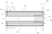
- FIG. 8 is a schematic cross-sectional view of a hollow fiber membrane module according to the prior art.
- the hollow fiber membrane module 700 comprises an outer case 710, an inner case 720 disposed inside the outer case 710, and a hollow fiber membrane bundle 730 consisting of a plurality of hollow fiber membranes filled in the annular gap between the outer case 710 and the inner case 720. At both ends of the plurality of hollow fiber membranes, the gaps between the plurality of hollow fiber membranes are sealed by a first sealing portion 741 and a second sealing portion 742 while leaving the hollow interior of each hollow fiber membrane open.
- the inner case 720 is provided with a first through hole 721, and the outer case 710 is provided with a second through hole 711.
- an intra-membrane passage (see arrow B) that runs through the inside of the multiple hollow fiber membranes is also formed.
- the gas flowing through the extra-membrane passage causes the hollow fiber membrane to sway so as to bulge outward, particularly near the second through-hole 711 (see the thick dotted line in the figure). If the hollow fiber membrane sways and causes an uneven filling state, this can affect quality, such as making the humidification efficiency more likely to vary, so generally, the hollow fiber membrane bundle 730 is protected by wrapping it with mesh 750 as shown in the figure.
- fuel cells have become larger in capacity, and as a result, there is a demand for even higher flow rates in the hollow fiber membrane modules provided in the humidifier. Therefore, simply wrapping the hollow fiber membrane bundle 730 with mesh 750 has become insufficient as a measure to suppress the oscillation of the hollow fiber membrane.
- the present invention provides a hollow fiber membrane module that can suppress the oscillation of the hollow fiber membrane.
- the present invention employs the following measures to solve the above problems.
- the hollow fiber membrane module of the present invention has the following features: A cylindrical outer case having openings at both ends; a cylindrical inner case having one open end and the other closed end, the inner case being disposed inside the outer case; a hollow fiber membrane bundle including a plurality of hollow fiber membranes filled in an annular gap between the outer case and the inner case; a first sealing portion that seals gaps between the plurality of hollow fiber membranes in a state in which the hollow interiors of the hollow fiber membranes are opened at one end sides of the outer case and the inner case; a second sealing portion that seals gaps between the plurality of hollow fiber membranes in a state in which the hollow interiors of the hollow fiber membranes are opened at the other end sides of the outer case and the inner case;
- a first through hole is provided in the inner case
- a second through hole is provided in the outer case, thereby forming an extra-membrane passage that passes from an opening of the inner case through the first through hole, passes outside the plurality of hollow fiber membranes, and
- the tubular member can suppress the oscillation of the hollow fiber membrane.
- the tubular member is provided with a plurality of third through holes, which provides a straightening effect for the fluid flowing through the extra-membrane passage.
- the present invention makes it possible to suppress the oscillation of the hollow fiber membrane.
- FIG. 1 is a front view of a hollow fiber membrane module according to a first embodiment of the present invention.
- FIG. 2 is a plan view of the hollow fiber membrane module according to the first embodiment of the present invention.
- FIG. 3 is a schematic cross-sectional view of a hollow fiber membrane module according to Example 1 of the present invention.
- FIG. 4 is a front view showing a modified example of the tubular member provided in the hollow fiber membrane module according to the first embodiment of the present invention.
- FIG. 5 is an explanatory diagram of a cylindrical member according to the first embodiment of the present invention.
- FIG. 6 is a schematic diagram showing an application example of the hollow fiber membrane module according to the embodiment of the present invention.
- FIG. 7 is a schematic cross-sectional view of a hollow fiber membrane module according to a second embodiment of the present invention.
- FIG. 8 is a schematic cross-sectional view of a hollow fiber membrane module according to the prior art.
- FIG. 1 is a front view of the hollow fiber membrane module according to the first embodiment of the present invention.
- Fig. 2 is a plan view (top view) of the hollow fiber membrane module according to the first embodiment of the present invention.
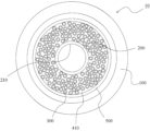
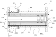
- Fig. 3 is a schematic cross-sectional view of the hollow fiber membrane module according to the first embodiment of the present invention, in which Fig. 3(a) is a cross-sectional view taken along line AA in Fig. 2, and Fig. 3(b) is a cross-sectional view taken along line BB of the outer case in Fig. 2.
- Fig. 3(a) is a cross-sectional view taken along line AA in Fig. 2
- Fig. 3(b) is a cross-sectional view taken along line BB of the outer case in Fig. 2.
- Fig. 3(a) is a cross-sectional view taken along line AA in Fig. 2
- Fig. 3(b) is a cross-sectional view taken along line BB of the outer case
- Fig. 4 is a front view showing a modified example of the cylindrical member provided in the hollow fiber membrane module according to the first embodiment of the present invention.
- Fig. 5 is an explanatory view of the cylindrical member according to the first embodiment of the present invention.
- the hollow fiber membrane module 10 includes an outer case 100, an inner case 200 disposed inside the outer case 100, and a hollow fiber membrane bundle 300 consisting of a plurality of hollow fiber membranes filled in the annular gap between the outer case 100 and the inner case 200.
- the outer case 100 is made of a cylindrical member with both ends open.
- the inner case 200 is made of a cylindrical member with one end open (see opening 210) and the other end closed (see closing portion 220).
- the outer case 100 and the inner case 200 are made of a material with high rigidity (for example, a metal such as aluminum or a hard resin such as PPS).
- the hollow fiber membrane module 10 also includes a first sealing portion 410 at one end of the outer case 100 and the inner case 200, which seals the gaps between the hollow fiber membranes while leaving the hollow interior of each hollow fiber membrane open.
- a protective layer 415 made of a highly flexible material such as silicone is provided on the inside of the first sealing portion 410 to prevent damage to the hollow fiber membranes at the interface with the first sealing portion 410 even if the hollow fiber membranes vibrate.
- the hollow fiber membrane module 10 also includes a second sealing portion 420 at the other end of the outer case 100 and the inner case 200, which seals the gaps between the hollow fiber membranes while leaving the hollow interior of each hollow fiber membrane open.
- a protective layer 425 is also provided on the inside of this second sealing portion 420.
- Polyphenylsulfone (PPSU) is preferably used as the material for the hollow fiber membrane, and epoxy resin is preferably used as the material for the first sealing portion 410 and the second sealing portion 420.
- the sealing portion also called the potting portion
- the first sealing portion 410 and the second sealing portion 420 can also be fixed to the outer case 100 and the inner case 200.
- the first sealing portion 410 and the second sealing portion 420 after hardening can also be fixed to the outer case 100 and the inner case 200 separately by an adhesive or the like.
- the inner case 200 described above has a plurality of first through holes 230 provided around the entire circumference. These first through holes 230 are provided in the inner case 200 at a position biased toward the other end side (the blocking portion 220 side).
- the outer case 100 also has a second through hole 130. This second through hole 130 is provided at a position biased toward one end side (the opening 210 side in the inner case 200).
- an extra-membrane passage (see arrow A shown by a solid line in FIG. 3) is formed that passes from the opening (opening 210) of the inner case 200 through the first through hole 230, passes through the outside of the membranes of the plurality of hollow fiber membranes, and reaches the second through hole 130.
- the outer case 100 has a first cylindrical portion 110 and a second cylindrical portion 120 having an inner diameter larger than that of the first cylindrical portion 110.
- the second through hole 130 is provided at one location in the circumferential direction of the second cylindrical portion 120.
- a relatively large gap is formed between the inner peripheral surface of the second cylindrical portion 120 and the outer peripheral surface of the hollow fiber membrane bundle 300 (see FIG. 3). Therefore, the fluid flowing through the membrane outer passage flows from the inside of the first cylindrical portion 110 to the second cylindrical portion 120, flows from the entire circumference of the hollow fiber membrane bundle 300 to the outside of the bundle, and then flows to the second through hole 130 (see FIG. 3(b)).
- intra-membrane passages are also formed that pass through the interiors of multiple hollow fiber membranes (see arrow B indicated by a dotted line in Figure 3(a)).
- the hollow fiber membrane module 10 can be suitably used as a humidifier for humidifying an electrolyte membrane provided in a fuel cell.
- the moist air generated in the fuel cell is used as the moist gas.
- the humidified gas (air) is then supplied to the electrolyte membrane provided in the fuel cell, thereby maintaining the electrolyte membrane in a moist state.
- the hollow fiber membrane module 10 can be suitably used as a humidification device for humidifying the electrolyte membrane provided in the fuel cell 50.
- a humidification device for humidifying the electrolyte membrane provided in the fuel cell 50.
- FIG. 6 the configuration in which the hollow fiber membrane module 10 is used as such a humidification device will be described.
- dry air is sent to the membrane inner flow path of the hollow fiber membrane module 10 by the compressor 60 (see arrow R1).
- the dry air flowing through the membrane inner flow path is humidified and discharged from the hollow fiber membrane module 10.
- This humidified wet air is sent to the fuel cell 50 (see arrow R2).
- the electrolyte membrane provided in the fuel cell 50 is maintained in a wet state.
- the wet air generated in the fuel cell 50 is then sent to the membrane outer flow path of the hollow fiber membrane module 10 (see arrow R3), and the dry air dehumidified by the membrane separation action of the hollow fiber membrane is discharged from the hollow fiber membrane module 10 (see arrow R4).
- the moist air generated in the fuel cell 50 has a high temperature, the temperature of the dry air sent from the compressor 60 is low, so the temperature of the moist air discharged from the hollow fiber membrane module 10 is low. In this way, the hollow fiber membrane module 10 also exhibits a heat exchange function.
- a configuration is adopted in which a tubular member 500 having a plurality of third through holes 510, each of which becomes a part of the membrane outer passage, is provided between the hollow fiber membrane bundle 300 and the outer case 100.
- the plurality of third through holes 510 are provided around the entire circumference.
- the tubular member 500 like the outer case 100 and the inner case 200, is also made of a highly rigid material (for example, a metal such as aluminum or a hard resin such as PPS). In other words, the tubular member 500 is made of a highly rigid material that is not deformed or damaged by a high flow rate of fluid.
- the tubular member 500 is provided, so that the oscillation of the hollow fiber membrane can be suppressed.
- the tubular member 500 is provided with a plurality of third through holes 510, the rectifying effect of the fluid flowing through the membrane extra-passage is exhibited.
- the fluid hits the hollow fiber membrane evenly, so that the pressure loss can be suppressed.
- the humidification performance can be stabilized.
- a configuration in which the hollow fiber membrane bundle 300 is wrapped with a mesh 600 for protection can be adopted as shown in FIG. 3.
- the tubular member 500 When the tubular member 500 is manufactured from a resin material, the tubular member 500 made of one piece can be obtained by a known molding technique using a mold. It is also possible to adopt a configuration in which the member is divided in the circumferential direction, as in the modified tubular member 500A shown in FIG. 4. Note that while the illustrated example shows an example in which the member is divided into two, a configuration in which the member is divided into three or more parts can also be adopted. When such a configuration is adopted, it is possible to reduce the size of the mold and also has the effect of improving the ease of assembly.
- the third through hole 510 is preferably set so as to suppress the shaking of the hollow fiber membrane and to effectively exert the straightening function.
- the width d of the third through hole 510 in the direction parallel to the multiple hollow fiber membranes may be set to 1 mm or more and 8 mm or less.
- the flow rate of the fluid passing through the third through hole 510 can be increased by increasing the ratio (called the aperture ratio) of the total area of all the third through holes 510 to the area of the surface of the outer peripheral surface of the tubular member 500 facing the membrane extra-passage (the surface facing the membrane extra-passage formed by the space between the inner peripheral surface of the second cylindrical portion 120 and the tubular member 500).
- range M indicates the range of the outer peripheral surface of the cylindrical member 500 that faces the extra-membrane passage.
- the left side of range M in the figure is the area where the first sealing portion 410 and the protective layer 415 are provided, and the right side of range M is the area where the inner peripheral surface of the first cylindrical portion 110 comes into contact.
- the hollow fiber membrane can be prevented from entering the hole, so the planar shape is not limited.
- the third through hole 510a shown in FIG. 5(b) can be elliptical, the third through hole 510b can be oval, the third through hole 510c can be rectangular, or the third through hole 510d can be circular.
- a circular shape makes it easier to disperse stress and increases the strength of the cylindrical member 500, it is preferable to make the planar shape of the through hole circular. Also, even if the rectifying effect is taken into consideration, it is preferable to make it circular.
- the planar shape of the through hole is an oval shape
- the area of the wall between adjacent through holes can be reduced compared to when it is circular, so that the opening rate can be easily increased.
- the planar shape of the through hole is an ellipse
- the through hole has no corners (edges) compared to when it is a rectangle, so that the hollow fiber membrane is prevented from being damaged by contact between the through hole and the hollow fiber membrane, and the strength of the tubular member 500 is prevented from decreasing near the through hole.
- the longitudinal direction of the ellipse should be a direction intersecting (preferably perpendicular to) the direction in which the hollow fiber membrane extends (the left-right direction in FIG. 3). This prevents the hollow fiber membrane from swinging and entering the inside of the third through hole 510b.
- the opening area can be increased while keeping the width d of the third through hole 510 below a certain value.
- a chamfer such as an R surface or a C surface on the inner peripheral surface side of the third through hole 510 as shown in FIG. 5(c). This makes it possible to more reliably prevent damage to the surface of the hollow fiber membrane. If a resin cylindrical member 500A divided in the circumferential direction as shown in FIG. 4 is used, the chamfer can be formed by die molding.
- FIG. 7 shows a second embodiment of the present invention.
- the outer case is made of one member, but in this embodiment, the outer case is made of two members. Since the other basic configurations and functions are the same as those in the first embodiment, the same components are denoted by the same reference numerals and the description thereof will be omitted.
- FIG. 7 is a schematic cross-sectional view of a hollow fiber membrane module according to the second embodiment of the present invention.
- the outer case 100 shown in the above-mentioned Example 1 is composed of one member (one part). In other words, the first cylindrical portion 110 and the second cylindrical portion 120 are integrally formed.
- the outer case 100A in this example comprises a first outer case 100X having the first cylindrical portion 110, and a second outer case 100Y having the second cylindrical portion 120.
- cylindrical member 550A in this embodiment is provided with an outward flange portion 555.
- the outward flange portion 555 is sandwiched between the end faces of these cases, thereby fixing the cylindrical member 550A.
- Example 1 a structure can be adopted in which the press-fitting force of the tubular member 500 into the outer case 100 is set high to fix the tubular member 500 to the outer case 100.
- the tubular member 550A can be fixed by sandwiching the outward flange portion 555 between the first outer case 100X and the second outer case 100Y, so there is no need to set the press-fitting force of the tubular member 550A high as in Example 1. Therefore, the ease of assembly of the hollow fiber membrane module can be improved.
- the hollow fiber membrane module 10 of this embodiment configured as described above can also achieve the same effects as in the first embodiment.
- the cylindrical member 550A of this embodiment can also be configured to be divided in the circumferential direction, as in the cylindrical member 500A of the modified example shown in FIG. 4.
- the third through hole 510 is as described in the first embodiment with reference to FIG. 5.
- the outer case and the inner case are made of cylindrical members. That is, when the case is cut in a direction perpendicular to the hollow fiber membranes, the inner and outer peripheral surfaces are circular.
- the shapes of the outer and inner cases applicable to the present invention are not limited. That is, when the case is cut in the above direction, the shapes of the inner and outer peripheral surfaces may be various shapes such as an ellipse, an oval, or a rectangle. Similarly, various shapes may be adopted for the cylindrical members, and the shape of the outer peripheral surface may be adapted to the shape of the inner peripheral surface of the outer case.
- Hollow fiber membrane module 100 100A: Outer case 100X: First outer case 100Y: Second outer case 110: First cylindrical portion 120: Second cylindrical portion 130: Second through hole 200: Inner case 210: Opening 220: Closing portion 230: First through hole 300: Hollow fiber membrane bundle 410: First sealing portion 415: Protective layer 420: Second sealing portion 425: Protective layer 500, 500A, 550A: Cylindrical member 510, 510a, 510b, 510c: Third through hole 555: Outward flange portion 600: Mesh
Landscapes
- Chemical & Material Sciences (AREA)
- Chemical Kinetics & Catalysis (AREA)
- Engineering & Computer Science (AREA)
- Manufacturing & Machinery (AREA)
- Life Sciences & Earth Sciences (AREA)
- Sustainable Development (AREA)
- Sustainable Energy (AREA)
- Electrochemistry (AREA)
- General Chemical & Material Sciences (AREA)
- Separation Using Semi-Permeable Membranes (AREA)
Abstract
Description
両端が開口する筒状の外ケースと、
一端が開口し、他端側が閉塞され、かつ前記外ケースの内部に配される筒状の内ケースと、
前記外ケースと前記内ケースとの間の環状隙間に充填される複数の中空糸膜からなる中空糸膜束と、
前記外ケース及び前記内ケースの一端側で、各中空糸膜の中空内部を開放させた状態で前記複数の中空糸膜間の隙間を封止する第1封止部と、
前記外ケース及び前記内ケースの他端側で、各中空糸膜の中空内部を開放させた状態で前記複数の中空糸膜間の隙間を封止する第2封止部と、
を備えると共に、
前記内ケースには第1の貫通孔が設けられ、かつ前記外ケースには第2の貫通孔が設けられることで、前記内ケースの開口から第1の貫通孔を通り、前記複数の中空糸膜の膜外を通って第2の貫通孔へと至る膜外通路と、
前記複数の中空糸膜の膜内を通る膜内通路と、
が形成される中空糸膜モジュールであって、
前記中空糸膜束と前記外ケースとの間には、それぞれ前記膜外通路の一部となる複数の第3の貫通孔を有する筒状部材が設けられることを特徴とする。
図1~図5を参照して、本発明の実施例1に係る中空糸膜モジュールについて説明する。図1は本発明の実施例1に係る中空糸膜モジュールの正面図である。図2は本発明の実施例1に係る中空糸膜モジュールの平面図(上面図)である。図3は本発明の実施例1に係る中空糸膜モジュールの模式的断面図であり、同図(a)は図2中のAA断面図であり、同図(b)は図2中の外ケースのBB断面図である。なお、図3(b)においては、内ケースと筒状部材の位置を点線にて示している。図4は本発明の実施例1に係る中空糸膜モジュールに備えられる筒状部材の変形例を示す正面図である。図5は本発明の実施例1に係る筒状部材の説明図である。
中空糸膜モジュール10は、外ケース100と、外ケース100の内部に配される内ケース200と、外ケース100と内ケース200との間の環状隙間に充填される複数の中空糸膜からなる中空糸膜束300とを備えている。外ケース100は、両端が開口する筒状の部材により構成される。また、内ケース200は、一端が開口(開口部210参照)し、他端側が閉塞(閉塞部220参照)される筒状の部材により構成される。これら外ケース100及び内ケース200は剛性の高い材料(例えば、アルミニウムなどの金属やPPSなどの硬質樹脂)により構成される。
本実施例に係る中空糸膜モジュール10によれば、筒状部材500が設けられることによって、中空糸膜の揺動を抑制することができる。そして、筒状部材500には複数の第3の貫通孔510が設けられているため、膜外通路を流れる流体の整流効果が発揮される。これにより、中空糸膜に流体が均等に当たるので、圧力損失を抑制することができる。また、加湿装置として用いる場合に、加湿性能の安定化を図ることができる。なお、中空糸膜の揺動をより一層抑制するために、図3に示すように、中空糸膜束300をメッシュ600で巻いて保護する構成を採用することもできる。
図7には、本発明の実施例2が示されている。上記実施例1では、外ケースが1部材により構成される場合を示したが、本実施例においては、外ケースが2部材により構成される場合を示す。その他の基本的な構成および作用については実施例1と同一なので、同一の構成部分については同一の符号を付して、その説明は省略する。図7は本発明の実施例2に係る中空糸膜モジュールの模式的断面図である。
上記実施例においては、外ケースと内ケースが円筒状の部材により構成される場合を示した。つまり、複数の中空糸膜に垂直な方向にケースを切断した場合、その内周面と外周面が円形の場合を示した。しかしながら、本発明に適用可能な外ケース及び内ケースの形状は限定されることはない。すなわち、上記の方向にケースを切断した場合、その内周面と外周面の形状は、楕円形、オーバル形状、矩形など各種の形状を採用し得る。筒状部材についても同様に各種の形状を採用することができ、その外周面の形状は外ケースの内周面の形状に適合させればよい。
100,100A:外ケース
100X:第1外ケース
100Y:第2外ケース
110:第1の円筒部
120:第2の円筒部
130:第2の貫通孔
200:内ケース
210:開口部
220:閉塞部
230:第1の貫通孔
300:中空糸膜束
410:第1封止部
415:保護層
420:第2封止部
425:保護層
500,500A,550A:筒状部材
510,510a,510b,510c:第3の貫通孔
555:外向きフランジ部
600:メッシュ
Claims (1)
- 両端が開口する筒状の外ケースと、
一端が開口し、他端側が閉塞され、かつ前記外ケースの内部に配される筒状の内ケースと、
前記外ケースと前記内ケースとの間の環状隙間に充填される複数の中空糸膜からなる中空糸膜束と、
前記外ケース及び前記内ケースの一端側で、各中空糸膜の中空内部を開放させた状態で前記複数の中空糸膜間の隙間を封止する第1封止部と、
前記外ケース及び前記内ケースの他端側で、各中空糸膜の中空内部を開放させた状態で前記複数の中空糸膜間の隙間を封止する第2封止部と、
を備えると共に、
前記内ケースには第1の貫通孔が設けられ、かつ前記外ケースには第2の貫通孔が設けられることで、前記内ケースの開口から第1の貫通孔を通り、前記複数の中空糸膜の膜外を通って第2の貫通孔へと至る膜外通路と、
前記複数の中空糸膜の膜内を通る膜内通路と、
が形成される中空糸膜モジュールであって、
前記中空糸膜束と前記外ケースとの間には、それぞれ前記膜外通路の一部となる複数の第3の貫通孔を有する筒状部材が設けられることを特徴とする中空糸膜モジュール。
Priority Applications (4)
| Application Number | Priority Date | Filing Date | Title |
|---|---|---|---|
| JP2025526142A JPWO2024253159A1 (ja) | 2023-06-08 | 2024-06-06 | |
| EP24819387.2A EP4725590A1 (en) | 2023-06-08 | 2024-06-06 | Hollow fiber membrane module |
| KR1020257030231A KR20250150045A (ko) | 2023-06-08 | 2024-06-06 | 중공사막 모듈 |
| CN202480022334.0A CN120916830A (zh) | 2023-06-08 | 2024-06-06 | 中空纤维膜组件 |
Applications Claiming Priority (2)
| Application Number | Priority Date | Filing Date | Title |
|---|---|---|---|
| JP2023094783 | 2023-06-08 | ||
| JP2023-094783 | 2023-06-08 |
Publications (1)
| Publication Number | Publication Date |
|---|---|
| WO2024253159A1 true WO2024253159A1 (ja) | 2024-12-12 |
Family
ID=93796078
Family Applications (1)
| Application Number | Title | Priority Date | Filing Date |
|---|---|---|---|
| PCT/JP2024/020705 Ceased WO2024253159A1 (ja) | 2023-06-08 | 2024-06-06 | 中空糸膜モジュール |
Country Status (5)
| Country | Link |
|---|---|
| EP (1) | EP4725590A1 (ja) |
| JP (1) | JPWO2024253159A1 (ja) |
| KR (1) | KR20250150045A (ja) |
| CN (1) | CN120916830A (ja) |
| WO (1) | WO2024253159A1 (ja) |
Citations (5)
| Publication number | Priority date | Publication date | Assignee | Title |
|---|---|---|---|---|
| JPS62204804A (ja) * | 1986-03-04 | 1987-09-09 | Daicel Chem Ind Ltd | 中空糸膜モジユ−ル |
| JP2002298883A (ja) * | 2001-03-30 | 2002-10-11 | Honda Motor Co Ltd | 加湿モジュール |
| JP2004006100A (ja) * | 2002-05-31 | 2004-01-08 | Nok Corp | 燃料電池の加湿装置 |
| WO2012043679A1 (ja) * | 2010-09-29 | 2012-04-05 | 旭化成ケミカルズ株式会社 | 中空糸膜モジュール、並びに、これを用いたろ過方法及び超純水製造システム |
| JP2020016366A (ja) | 2018-07-24 | 2020-01-30 | 本田技研工業株式会社 | 加湿器 |
-
2024
- 2024-06-06 EP EP24819387.2A patent/EP4725590A1/en active Pending
- 2024-06-06 CN CN202480022334.0A patent/CN120916830A/zh active Pending
- 2024-06-06 KR KR1020257030231A patent/KR20250150045A/ko active Pending
- 2024-06-06 JP JP2025526142A patent/JPWO2024253159A1/ja active Pending
- 2024-06-06 WO PCT/JP2024/020705 patent/WO2024253159A1/ja not_active Ceased
Patent Citations (5)
| Publication number | Priority date | Publication date | Assignee | Title |
|---|---|---|---|---|
| JPS62204804A (ja) * | 1986-03-04 | 1987-09-09 | Daicel Chem Ind Ltd | 中空糸膜モジユ−ル |
| JP2002298883A (ja) * | 2001-03-30 | 2002-10-11 | Honda Motor Co Ltd | 加湿モジュール |
| JP2004006100A (ja) * | 2002-05-31 | 2004-01-08 | Nok Corp | 燃料電池の加湿装置 |
| WO2012043679A1 (ja) * | 2010-09-29 | 2012-04-05 | 旭化成ケミカルズ株式会社 | 中空糸膜モジュール、並びに、これを用いたろ過方法及び超純水製造システム |
| JP2020016366A (ja) | 2018-07-24 | 2020-01-30 | 本田技研工業株式会社 | 加湿器 |
Non-Patent Citations (1)
| Title |
|---|
| See also references of EP4725590A1 |
Also Published As
| Publication number | Publication date |
|---|---|
| JPWO2024253159A1 (ja) | 2024-12-12 |
| CN120916830A (zh) | 2025-11-07 |
| KR20250150045A (ko) | 2025-10-17 |
| EP4725590A1 (en) | 2026-04-15 |
Similar Documents
| Publication | Publication Date | Title |
|---|---|---|
| JP5354248B2 (ja) | 加湿膜モジュール | |
| JP7607122B2 (ja) | 中空糸膜モジュール | |
| JP4610715B2 (ja) | 加湿装置 | |
| JP6918097B2 (ja) | 中空糸膜モジュール | |
| JP2004209418A (ja) | 中空糸膜モジュール | |
| JP7026797B2 (ja) | 中空糸膜モジュール | |
| WO2024253159A1 (ja) | 中空糸膜モジュール | |
| JP6251847B2 (ja) | 加湿器用の加湿ブロックの製造方法 | |
| JP2004202478A (ja) | 膜モジュール | |
| JP7625698B2 (ja) | 中空糸膜モジュール | |
| CA3288693A1 (en) | Hollow fiber membrane module | |
| JP4631608B2 (ja) | 中空糸膜モジュール及びその製造方法 | |
| JP2019058896A (ja) | 中空糸膜モジュール | |
| KR20230171036A (ko) | 중공사 막 모듈 | |
| WO2024176963A1 (ja) | 中空糸膜モジュール | |
| TW202009049A (zh) | 分離裝置 | |
| JP2012130864A (ja) | 中空糸膜モジュール | |
| WO2024176970A1 (ja) | 中空糸膜モジュール | |
| WO2024176959A1 (ja) | 中空糸膜モジュール | |
| JP2010127583A (ja) | 加湿装置 | |
| JP2018199098A (ja) | 膜分離装置 | |
| US20250096286A1 (en) | Membrane stacking unit | |
| JP2025144722A (ja) | 中空糸膜モジュール |
Legal Events
| Date | Code | Title | Description |
|---|---|---|---|
| 121 | Ep: the epo has been informed by wipo that ep was designated in this application |
Ref document number: 24819387 Country of ref document: EP Kind code of ref document: A1 |
|
| ENP | Entry into the national phase |
Ref document number: 1020257030231 Country of ref document: KR Free format text: ST27 STATUS EVENT CODE: A-0-1-A10-A15-NAP-PA0105 (AS PROVIDED BY THE NATIONAL OFFICE) |
|
| WWE | Wipo information: entry into national phase |
Ref document number: 202480022334.0 Country of ref document: CN |
|
| WWP | Wipo information: published in national office |
Ref document number: 1020257030231 Country of ref document: KR |
|
| ENP | Entry into the national phase |
Ref document number: 2025526142 Country of ref document: JP Kind code of ref document: A |
|
| WWP | Wipo information: published in national office |
Ref document number: 202480022334.0 Country of ref document: CN |
|
| WWE | Wipo information: entry into national phase |
Ref document number: 2024819387 Country of ref document: EP |
|
| NENP | Non-entry into the national phase |
Ref country code: DE |
|
| ENP | Entry into the national phase |
Ref document number: 2024819387 Country of ref document: EP Effective date: 20260108 |
|
| ENP | Entry into the national phase |
Ref document number: 2024819387 Country of ref document: EP Effective date: 20260108 |
|
| ENP | Entry into the national phase |
Ref document number: 2024819387 Country of ref document: EP Effective date: 20260108 |
|
| ENP | Entry into the national phase |
Ref document number: 2024819387 Country of ref document: EP Effective date: 20260108 |
|
| ENP | Entry into the national phase |
Ref document number: 2024819387 Country of ref document: EP Effective date: 20260108 |
|
| WWP | Wipo information: published in national office |
Ref document number: 2024819387 Country of ref document: EP |