WO2024253136A1 - 水処理装置及び水処理方法 - Google Patents
水処理装置及び水処理方法 Download PDFInfo
- Publication number
- WO2024253136A1 WO2024253136A1 PCT/JP2024/020557 JP2024020557W WO2024253136A1 WO 2024253136 A1 WO2024253136 A1 WO 2024253136A1 JP 2024020557 W JP2024020557 W JP 2024020557W WO 2024253136 A1 WO2024253136 A1 WO 2024253136A1
- Authority
- WO
- WIPO (PCT)
- Prior art keywords
- water
- treated
- ozone
- substance
- tank
- Prior art date
- Legal status (The legal status is an assumption and is not a legal conclusion. Google has not performed a legal analysis and makes no representation as to the accuracy of the status listed.)
- Ceased
Links
Images





Classifications
-
- C—CHEMISTRY; METALLURGY
- C02—TREATMENT OF WATER, WASTE WATER, SEWAGE, OR SLUDGE
- C02F—TREATMENT OF WATER, WASTE WATER, SEWAGE, OR SLUDGE
- C02F9/00—Multistage treatment of water, waste water or sewage
-
- C—CHEMISTRY; METALLURGY
- C02—TREATMENT OF WATER, WASTE WATER, SEWAGE, OR SLUDGE
- C02F—TREATMENT OF WATER, WASTE WATER, SEWAGE, OR SLUDGE
- C02F1/00—Treatment of water, waste water, or sewage
- C02F1/28—Treatment of water, waste water, or sewage by sorption
- C02F1/283—Treatment of water, waste water, or sewage by sorption using coal, charred products, or inorganic mixtures containing them
-
- C—CHEMISTRY; METALLURGY
- C02—TREATMENT OF WATER, WASTE WATER, SEWAGE, OR SLUDGE
- C02F—TREATMENT OF WATER, WASTE WATER, SEWAGE, OR SLUDGE
- C02F1/00—Treatment of water, waste water, or sewage
- C02F1/42—Treatment of water, waste water, or sewage by ion-exchange
-
- C—CHEMISTRY; METALLURGY
- C02—TREATMENT OF WATER, WASTE WATER, SEWAGE, OR SLUDGE
- C02F—TREATMENT OF WATER, WASTE WATER, SEWAGE, OR SLUDGE
- C02F1/00—Treatment of water, waste water, or sewage
- C02F1/44—Treatment of water, waste water, or sewage by dialysis, osmosis or reverse osmosis
- C02F1/441—Treatment of water, waste water, or sewage by dialysis, osmosis or reverse osmosis by reverse osmosis
-
- C—CHEMISTRY; METALLURGY
- C02—TREATMENT OF WATER, WASTE WATER, SEWAGE, OR SLUDGE
- C02F—TREATMENT OF WATER, WASTE WATER, SEWAGE, OR SLUDGE
- C02F1/00—Treatment of water, waste water, or sewage
- C02F1/44—Treatment of water, waste water, or sewage by dialysis, osmosis or reverse osmosis
- C02F1/444—Treatment of water, waste water, or sewage by dialysis, osmosis or reverse osmosis by ultrafiltration or microfiltration
-
- C—CHEMISTRY; METALLURGY
- C02—TREATMENT OF WATER, WASTE WATER, SEWAGE, OR SLUDGE
- C02F—TREATMENT OF WATER, WASTE WATER, SEWAGE, OR SLUDGE
- C02F1/00—Treatment of water, waste water, or sewage
- C02F1/46—Treatment of water, waste water, or sewage by electrochemical methods
- C02F1/4608—Treatment of water, waste water, or sewage by electrochemical methods using electrical discharges
-
- C—CHEMISTRY; METALLURGY
- C02—TREATMENT OF WATER, WASTE WATER, SEWAGE, OR SLUDGE
- C02F—TREATMENT OF WATER, WASTE WATER, SEWAGE, OR SLUDGE
- C02F1/00—Treatment of water, waste water, or sewage
- C02F1/72—Treatment of water, waste water, or sewage by oxidation
- C02F1/78—Treatment of water, waste water, or sewage by oxidation with ozone
-
- C—CHEMISTRY; METALLURGY
- C02—TREATMENT OF WATER, WASTE WATER, SEWAGE, OR SLUDGE
- C02F—TREATMENT OF WATER, WASTE WATER, SEWAGE, OR SLUDGE
- C02F2101/00—Nature of the contaminant
- C02F2101/30—Organic compounds
- C02F2101/36—Organic compounds containing halogen
-
- C—CHEMISTRY; METALLURGY
- C02—TREATMENT OF WATER, WASTE WATER, SEWAGE, OR SLUDGE
- C02F—TREATMENT OF WATER, WASTE WATER, SEWAGE, OR SLUDGE
- C02F2303/00—Specific treatment goals
- C02F2303/16—Regeneration of sorbents, filters
Definitions
- the present invention relates to a water treatment technology that decomposes organic matter contained in water, and in particular to a water treatment technology that decomposes difficult-to-decompose organic matter.
- Liquid surface plasma discharge is used to purify water quality for treating various industrial wastewater and lake water, and to ensure drinking water and industrial water (for example, Patent Document 1).
- the water treatment device in Patent Document 1 arranges a cathode in the liquid phase of a reaction tank into which the water to be treated is introduced, while an anode is placed in the gas phase of the reaction tank, and plasma discharge is generated between the cathode and anode, thereby performing purification processing such as decomposing organic matter and chemical substances in the water to be treated.
- Patent Document 1 describes an example of the water treatment device applied to purifying lake water.
- raw water is fed to a pretreatment device equipped with a filter, an aeration tank, and an adsorption filtration tank (a charcoal tank and a zeolite tank), and the resulting pretreated water is supplied to the water treatment device.
- a pretreatment device equipped with a filter, an aeration tank, and an adsorption filtration tank (a charcoal tank and a zeolite tank), and the resulting pretreated water is supplied to the water treatment device.
- the time (retention time) required for the raw water to be supplied to a water treatment system having the pretreatment device and the water treatment device and for it to be obtained as recycled water is long. It is desirable to supply industrial wastewater to the water treatment system and regenerate it as industrial water in a short time.
- the concentration of the treated substances in the pretreated water obtained by the pretreatment device is very low. It is inefficient to treat low-concentration treated substances by applying large amounts of energy such as ozone or plasma discharge.
- the filtration capacity of the adsorption filtration tank gradually decreases with continuous use.
- the filter media in the adsorption filtration tank is washed with water or water containing an acid or base, such as by surface washing or backwashing, in order to restore the filtration capacity.
- the water used to wash the filter media contains a high concentration of the substances to be treated that have been separated from the raw water, and so it is necessary to detoxify the substances.
- the present invention aims to obtain reused water in a relatively short time after subjecting raw water to water treatment. It also aims to treat wastewater in which the treated substances have been concentrated during the water treatment process in an energy-efficient manner.
- the water treatment device includes a filtered water storage tank for storing filtered water containing the substance to be treated that is to be subjected to filtration, an ozone water mixing tank for mixing the concentrated wastewater of the substance to be treated, which is obtained by concentrating the substance to be treated and separated from the filtered water by the filtration, with ozone water, and a pulse plasma discharge tank for applying pulse plasma to the mixture of the concentrated wastewater of the substance to be treated and the ozone water.
- the water treatment device is provided with a power source capable of generating the pulse plasma that breaks down inter-element bonds in the material to be treated that have a bond energy higher than the oxidation potential of hydroxyl radicals.
- the interelement bond is a bond between a carbon element and a fluorine element.
- the concentrated wastewater of the treated substance is generated during the process of regenerating the adsorbent added to the filtered water storage tank.
- the mixed liquid is aerated in the water treatment device.
- the adsorbent is activated carbon and/or ion exchange resin.
- the concentrated wastewater of the treated material is produced by filtering the filtered water from the filtered water storage tank containing activated sludge using a first filtration membrane to separate first filtrate, and then filtering the first filtrate using a second filtration membrane with a smaller pore size than the first filtration membrane.
- the water treatment method includes a step of filtering filtered water containing the substance to be treated to separate the substance to be treated from the filtered water, a step of mixing a concentrated effluent of the substance to be treated, in which the substance to be treated is concentrated, with ozone water, and a step of applying pulse plasma to the mixture of the concentrated effluent of the substance to be treated and the ozone water.
- reused water can be obtained in a relatively short time after subjecting raw water to water treatment.
- wastewater in which the treated substances have been concentrated during the water treatment process can be treated with high energy efficiency.
- FIG. 1 is a schematic configuration diagram of a water treatment device according to a first embodiment of the present invention.
- FIG. 2 is a schematic configuration diagram of a water treatment device according to a second embodiment of the present invention.
- FIG. 1 is a schematic configuration diagram of a water treatment device according to a third embodiment of the present invention. A diagram showing the relationship between the oxidation potential of various free radicals and the bond energy between various elements.
- FIG. 1A is a structural formula of perfluorooctanecarboxylic acid, which is an example of an organic fluorine compound
- FIG. 1B is an explanatory diagram of the decomposition process of perfluorooctanecarboxylic acid.
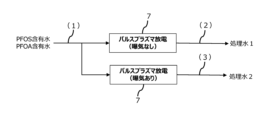
- FIG. 2 is a flow diagram of a pre-test of the pulse plasma discharge treatment process of the present invention.
- 1 is a schematic configuration diagram of a water treatment device according to an embodiment of the present invention. PFOS concentration, fluoride ion concentration, and PFOS reduction rate for water quality evaluation points (1), (2), and (3) after pulse plasma discharge treatment of PFOS-containing water in a preliminary test.
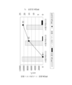
- PFOA concentration, fluoride ion concentration, and PFOA reduction rate for water quality evaluation points (1), (2), and (3) after pulse plasma discharge treatment of PFOA-containing water in a preliminary test The reduction rate of the combined total amount of PFOS and PFOA, the combined total amount of PFOS and PFOA, and the total amount of fluoride ions for water quality evaluation points (1), (2), and (3) when the water to be treated is treated using the ozone water mixing treatment process and the pulse plasma discharge treatment process.
- the water treatment method and water treatment device of the present invention decompose the substances to be treated in an energy-efficient manner by mixing pretreated water (hereinafter, concentrated wastewater of substances to be treated), in which the substances to be treated have been concentrated in advance by solid-liquid separation of raw water, with ozone water, and then exposing the water to pulse plasma.
- pretreated water hereinafter, concentrated wastewater of substances to be treated
- the present invention can decompose not only organic substances that can be decomposed by general water treatment, but also refractory organic substances such as organofluorine compounds (hereinafter, PFAS), which were difficult to decompose by conventional water treatment devices.
- PFAS organofluorine compounds
- the water treatment device 1 includes a filtered water storage tank 2, an adsorbent adding means 3, an adsorbent transporting means 4, an adsorbent regenerating device 5, an ozone water mixing tank 6, and a pulse plasma discharge tank 7.
- the filtered water storage tank 2 stores the filtered water containing the substances to be treated that are to be subjected to filtration.
- a membrane filtration device 20 is immersed in the filtered water.
- activated carbon is added to the filtered water as an adsorbent.
- the membrane filtration device 20 is equipped with a filtration membrane 21 that sucks the filtered water and separates the filtrate water that does not contain the substances to be treated from the filtered water.
- a ceramic membrane is preferable as the filtration membrane 21.
- this ceramic membrane is made of alumina-based ceramics (mainly composed of alumina).
- the filtered water is supplied to a treatment facility not shown.
- the substances to be treated are adsorbed by the added activated carbon.
- the adsorbent adding means 3 adds the activated carbon to the filtered water in the filtered water storage tank 2.
- a well-known powder supplying device such as a powder feeder used in wastewater treatment technology is applied.
- the adsorbent transfer means 4 transfers the activated carbon that has adsorbed the substance to be treated from the filtered water storage tank 2 to the adsorbent regeneration device 5.
- a pump that transfers the liquid phase containing the activated carbon from the filtered water storage tank 2 to the adsorbent regeneration device 5 is used as the adsorbent transfer means 4.
- the adsorbent regeneration device 5 separates the activated carbon from the liquid phase containing the activated carbon and desorbs the treated substance from the activated carbon by chemical treatment, thereby regenerating the activated carbon.
- a well-known separation device in wastewater treatment technology such as a screen device, is used to separate the activated carbon.
- the chemical treatment is performed using a well-known chemical treatment method in which the activated carbon is brought into contact with an alkaline and acidic regenerating chemical solution, as described in Patent Document 2, for example.
- the ozone water mixing tank 6 decomposes inter-element bonds other than C-F bonds in the treated substance by mixing the concentrated wastewater of the treated substance, which is obtained by concentrating the treated substance desorbed from the activated carbon in the adsorbent regeneration device 5, with ozone water in a batch or continuous manner.
- the ozone water can be made by dissolving ozone gas in raw water.
- This dissolution method can be any existing method for producing ozone water, such as a method in which raw water and ozone gas are fed into a gas-liquid mixer to produce ozone water.
- the raw water can be any suitable water that can dissolve ozone gas, such as pure water or ultrapure water. If necessary, the purity of the raw water can be increased using a known pure water production device.
- the ozone gas can be generated by a known ozone gas generator.
- An example of the ozone gas generator is the pure ozone generator manufactured by Meidensha and described in Patent Document 3.
- ozone gas When ozone gas is generated by the pure ozone generator, ozone gas with an ozone concentration of 50% by volume or more and an ozone partial pressure of 30 kPa (abs) or less can be supplied to the gas-liquid mixer, so that high-concentration (100 ppm or more) ozone water can be safely generated.
- gas-liquid mixer examples include an ejector, an aspirator, a jet pump, etc., but are not limited to these and various configurations can be applied.
- the gas-liquid mixer has, for example, a raw water flow passage through which the received raw water flows, and an ozone gas inlet passage connected to the raw water flow passage for introducing the received ozone gas into the raw water flow passage.
- a suction pressure is generated according to Bernoulli's theorem in accordance with the flow rate (flow velocity) of the raw water flowing through the raw water flow passage.
- steam is generated in accordance with the saturated vapor pressure of the raw water.
- a suction range is derived based on the raw water and the ozone gas receiving pressure of the gas-liquid mixer, which is the raw water temperature range in which the vapor pressure of the ozone gas introduction passage is smaller than the receiving pressure.
- the suction range is set appropriately (for example, 25°C or less as described in Patent Document 4) according to the general solubility characteristics of gas in raw water (the solubility tends to increase as the temperature of the raw water decreases). Therefore, if the temperature of the raw water falls outside the suction range, it is adjusted to within the range by adjusting the temperature of the raw water before it is fed to the gas-liquid mixer or by adjusting the temperature of the gas-liquid mixer into which the raw water is introduced.
- the ozone water generated in the gas-liquid mixer may be mixed with a concentration-adjusting gas to stabilize the ozone concentration, or may be circulated to an ozone water generating unit equipped with the gas-liquid mixer or temporarily stored.
- a concentration-adjusting gas for example, a method of injecting carbon dioxide gas or the like into the ozone water to acidify the ozone water can be given.
- the above ozone water generation method can safely generate high concentration ozone water of 100 ppm or more (e.g., 300 to 400 ppm).
- pulse plasma is applied to the mixture of the concentrated wastewater of the treated substance and the ozone water supplied from the ozone water mixing tank 6.
- pulse plasma discharge treatment or pulse discharge treatment.
- the pulsed plasma can be supplied, for example, by applying a pulsed voltage between a pair of electrodes immersed in the mixed liquid, thereby discharging the pulsed plasma into the mixed liquid.
- a pulsed voltage is applied between one electrode placed in the gas phase near the stable liquid surface of the mixed liquid in the pulsed plasma discharge tank 7 and the other electrode immersed in the mixed liquid, thereby discharging the pulsed plasma into the mixed liquid.
- the other electrode may be in the form of a pulsed plasma discharge vessel 7 shown in FIG. 8.
- a pulse voltage is applied between the electrode 72 as the one electrode and the conductive pulsed plasma discharge vessel 7 functioning as the other electrode, and the pulsed plasma discharged from one end of the electrode 72 near the liquid surface is supplied to the mixed liquid via the gas phase near the liquid surface.
- the power supply for applying the pulse voltage is capable of generating the pulse plasma that breaks down inter-element bonds (e.g., bonds between carbon and fluorine elements) of the material to be treated that have a bond energy higher than the oxidation potential of hydroxyl radicals (hereinafter, OH).
- the electrodes and power supply device described in Patent Document 5 are used as the electrodes and power supply.
- the mixed liquid in the pulse plasma discharge tank 7 may be aerated with an aeration device 71 as shown in FIG. 8. This aeration stabilizes the discharge of the pulse plasma and improves the reduction rate of PFOS and PFOA.
- the activated carbon is added to the filtered water introduced into the filtered water storage tank 2 by the adsorbent adding means 3.
- the substances to be treated in the filtered water are adsorbed by the activated carbon.
- the filtration membrane 21 of the membrane filtration device 20 immersed in the filtered water has pores small enough to block and capture the activated carbon, so the activated carbon is removed by the filtration membrane 21.
- the adsorption of the substances to be treated and the separation of the activated carbon can be applied to large-scale water treatment, and filtered water can be obtained quickly and in large quantities by the filtration membrane 21.
- the liquid phase containing the activated carbon that has adsorbed the substances to be treated is transferred to the adsorbent regeneration device 5 by the adsorbent transfer means 4.
- the filtrate that does not contain the substances to be treated separated by the filtration membrane 21 is transferred outside the system.
- the activated carbon separated from the liquid phase by the screen or the like comes into contact with the regeneration liquid, causing the treated substance to be desorbed from the activated carbon and regenerating the activated carbon.
- Easily decomposable organic matter may be decomposed during the regeneration process, but if the treated substance is a difficult-to-decompose organic matter such as PFAS, it is not decomposed and is concentrated to a high concentration in the regeneration effluent. This concentrated effluent of the treated substance is supplied to the ozone water mixing tank 6.
- the substance to be treated is PFOA (perfluorooctane carboxylic acid), which is a type of PFAS shown in FIG.
- Non-Patent Document 2 Non-Patent Document 2
- PFOA containing C-F bonds or its decomposition products are not completely decomposed by the oxidizing power of the active species, and the liquid phase containing them is supplied to the pulse plasma discharge tank 7.
- the mixed liquid introduced from the ozone water mixing tank 6 is aerated.
- the inter-element bonds of the treated material which have a bond energy higher than the oxidation potential of -OH, are broken down by the pulse plasma generated by application of the pulse voltage.
- the decomposition products of PFOA which contain C-F bonds contained in the liquid phase supplied from the ozone water mixing tank 6, are broken down into fluorine ions and carbon dioxide gas by the pulse plasma.
- reusable water can be produced by the first filtration using a combination of activated carbon and a ceramic membrane, so the residence time in the system can be shortened compared to the conventional method (Patent Document 1).
- energy efficiency is improved because the treated substances are decomposed using ozone water and pulse plasma after being concentrated.
- the water treatment device 1 of the second embodiment shown in Fig. 2 is the same as that of the first embodiment, except that an ion exchange resin is used as an adsorbent instead of activated carbon.
- the ion exchange resin may be a well-known ion exchange resin as described in Patent Document 6, for example, and the ion exchange resin is regenerated by a regenerating liquid containing a regenerant such as an acid or alkali as described in the same patent document. It is clear that the above-described embodiment can also achieve the same effects as those of the first embodiment.
- the ion exchange resin may be used together with the activated carbon of the first embodiment.
- the water treatment device 1 of the third embodiment of the present invention shown in FIG. 3 is the same as the first and second embodiments except that it employs a membrane bioreactor (hereinafter, referred to as MBR) method, activate sludge is added to the to-be-filtered water storage tank 2 instead of an adsorbent, and a reverse osmosis membrane filter 8 is provided instead of the adsorbent regeneration device 5.
- MBR membrane bioreactor
- the filtered water storage tank 2 serves as pretreatment for the reverse osmosis membrane filter 8. Therefore, in the filtered water storage tank 2 of this embodiment, it is not necessary to add the adsorbent.
- MBR which treats organic matter that can be decomposed by normal biological treatment using activated sludge in the filtered water storage tank 2, is effective from the perspective of improving the efficiency of subsequent treatment stages (reverse osmosis membrane filter 8, ozone water mixing tank 6, and pulse plasma discharge tank 7).
- the filtered water introduced into the filtered water storage tank 2 is aerated and agitated.
- Organic matter in the liquid phase in the filtered water storage tank 2 that can be decomposed by normal biological treatment is decomposed by the activated sludge.
- the filtration membrane 21 of the membrane filtration device 20 in the filtered water storage tank 2 which corresponds to the first filtration membrane in this embodiment, has pores small enough to block and capture the activated sludge, so the activated sludge is separated from the first filtrate water by the filtration membrane 21.
- the first filtrate water is supplied to the reverse osmosis membrane filter 8 by pumping.
- the first filtrate is separated into a second filtrate that does not contain the treated substance (hard-to-decompose organic matter) and a concentrated effluent of the treated substance by a reverse osmosis membrane (hereinafter, RO membrane) 81, which corresponds to the second filtration membrane of this embodiment.
- the first filtrate does not contain solid matter that is alienated from the RO membrane 81 or organic matter that is easily decomposed, but still contains the treated substance such as PFAS.
- the RO membrane 81 has pores with a pore size smaller than that of the filtration membrane 21, which is sufficient to block and capture the treated substance, so that the treated substance is removed from the first filtrate.
- the concentrated effluent of the treated substance is sequentially supplied to the ozone water mixing tank 6 and the pulse plasma discharge tank 7 as in the first and second embodiments. Meanwhile, the second filtrate is transferred to the outside of the system.
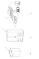
- the present invention is not limited to the above-described embodiment, but can be applied to various industries and service formats as exemplified in FIG. 6, and the same effects as those of the above-described embodiment can be obtained.
- the water treatment device 1 in FIG. 1(a) is equipped with a batch-type ozone water mixing tank 6 and pulse plasma discharge tank 7, which have a treated water volume of, for example, 100 L/h, to which the concentrated wastewater of the substance to be treated that has been collected in advance is supplied.
- the water treatment device 1 of this embodiment does not have a power source such as a pump, and can be installed in a small facility such as a laboratory.
- the water treatment device 1 in FIG. 1(b) is equipped with a batch-type ozone water mixing tank 6 and pulse plasma discharge tank 7 with a treatment water volume of, for example, 100-1000 L/h, and can be installed in an existing medium-sized facility. It can also be equipped with power sources such as pumps so that it can operate as a standalone device.
- the water treatment device 1 in FIG. 1(c) is equipped with a batch or continuous ozone water mixing tank 6 and a pulse plasma discharge tank 7 with a treated water volume of, for example, 1000 L/h or more, and is applied to large-scale facilities that are expected to treat the entire volume, such as existing or newly constructed water purification plants 9.
- the ozone water mixing tank 6 in this embodiment is supplied with concentrated effluent of the substance to be treated that has been generated in advance, for example, at the water purification plant 9 using the adsorbent and membrane filtration.
- the filtration membrane applied to the filtered water storage tank of the water treatment device of the present invention is not limited to the submerged filtration membrane of embodiments 1 to 3, but an external filtration membrane can also be used.
- PFOS-containing water is prepared by dissolving PFOS in tap water to a PFOS concentration of 7,200 ⁇ g/L.
- PFOA-containing water is prepared by dissolving PFOA in tap water to a PFOA concentration of 11,000 ⁇ g/L.
- the pulse plasma discharge tank 7 without aeration and with aeration shown in FIG. 7 are equipped with an aeration device 71, an electrode 72, and a pulse power supply 73, as in the pulse plasma discharge tank 7 in FIG. 8.
- the tank body 70 of the pulse plasma discharge tank 7 functions as a GND electrode.
- the aeration device 71 is equipped with a blower 74 that introduces air from the atmosphere, and an aeration pipe 75 that is connected to the blower 74 and aerates the water to be treated in the pulse plasma discharge tank 7.
- the electrode 72 is made of a round rod electrode for high voltage output, and its tip is placed in the gas phase near the liquid surface in the pulse plasma discharge tank 7, and generates pulse plasma between the pulse plasma discharge tank 7 and the pulse plasma discharge tank 7 by applying a pulse voltage from the pulse power supply 73.
- the pulse plasma is supplied to the mixed liquid through the gas phase near the liquid surface, flows along the liquid surface of the mixed liquid, and flows to the ground (earth) through the pulse plasma discharge tank 7.
- the tank body 70 of the pulse plasma discharge tank 7 was constructed as a stainless steel cylindrical container with an inner diameter of 100 mm and a capacity of 700 mL. 300 mL of the water to be treated was placed in the tank body 70, and a stainless steel round rod electrode 72 with a diameter of 3 mm was placed in the gas phase near the liquid level in the center of the tank body 70 (1 mm above the liquid level). A pulsed plasma discharge was generated by applying a high voltage pulse between the electrode 72 and the tank body 70 using a pulsed power source 73. In the pulse plasma discharge tank 7 with aeration, air aeration was also used to agitate the water to be treated in the tank body 70 and to cause discharge within the air bubbles. The conditions for pulse plasma discharge of the water to be treated are shown in Table 1 below.
- the PFOS concentration, fluoride ion concentration, and PFOS reduction rate of PFOS-containing water after pulse discharge treatment in this preliminary test are shown in Figure 9.
- the PFOS concentration, fluoride ion concentration, and PFOS reduction rate of PFOA-containing water after pulse discharge treatment are shown in Figure 10.
- the PFOS concentration was lower and the fluoride ion concentration was higher at water quality evaluation point (3) compared to water quality evaluation point (2).
- the PFOS reduction rate by pulse plasma discharge treatment with aeration was 40% higher than that by pulse discharge treatment without aeration.
- Example 1 As the treated water in Example 1, water containing PFOS and PFOA (PFOS concentration: 3,300 ⁇ g/L, PFOA concentration: 5,300 ⁇ g/L, combined concentration of PFOS and PFOA: 8,600 ⁇ g/L) was used. This treated water was prepared by dissolving reagent grade PFOS and PFOA in tap water, as in the preliminary test. This treated water was treated with ozone water in the ozone water mixing tank 6 shown in FIG. 8 and then subjected to pulse plasma discharge treatment in the pulse plasma discharge tank 7 to obtain the treated water in Example 1.
- the ozone water mixing treatment process is carried out in the ozone water mixing tank 6 shown in FIG. 8.
- the water to be treated and high-concentration ozone water were supplied to the ozone water mixing tank 6 and mixed.
- This treatment was a batch process, and the ozone dissolved in the high-concentration ozone water and the active oxidizing species generated when the ozone decomposed were used to oxidize and decompose the organic matter including PFAS in the water to be treated.
- the pulse discharge treatment process is carried out in the pulse plasma discharge tank 7 in Fig. 8.
- the treated water (mixture of water to be treated and high-concentration ozone) from the ozone water mixing treatment process (ozone water mixing tank 6) is supplied to the pulse plasma discharge tank 7.
- the aeration device 71 aerates the mixed liquid with air by a blower 74 via an aeration tube 75.
- the tip of the electrode 72 is disposed in the gas phase near the liquid surface in the pulse plasma discharge tank 7, and a pulsed plasma is generated between the electrode 72 and the pulse plasma discharge tank 7 by application of a pulsed voltage from a pulsed power supply 73.
- the pulsed plasma is supplied to the mixed liquid through the gas phase near the liquid surface, flows along the liquid surface of the mixed liquid, and flows to the ground (earth) through the pulse plasma discharge tank 7.
- the treated water from the ozone water mixing treatment process was light purple even immediately before the pulse discharge treatment process, and the pulse discharge treatment was carried out in the presence of dissolved ozone.
- the pulse discharge treatment was carried out while aerating the mixed liquid in the pulse plasma discharge tank 7 with air using the aeration device 71.
- the conditions for the pulse discharge treatment process in this embodiment are the same as those shown in Table 1.
- water quality evaluation point (1) is the water to be treated before being subjected to the ozone water mixing treatment process (ozone water mixing tank 6).
- Water quality evaluation point (2) is the treated water from the ozone water mixing treatment process.
- Water quality evaluation point (3) is the treated water from the pulse discharge treatment process (pulse plasma discharge tank 7).
- the water to be treated and high-concentration ozone water are mixed at a 1:1 ratio, so the concentration of substances in the raw water is halved due to the dilution effect.
- the substances contained in the water quality evaluation points (1), (2), and (3) were displayed and evaluated as total amounts rather than concentrations.
- the combination of ozone water contact treatment and pulse discharge treatment reduced the combined total amount of PFOS and PFOA by 43%.
- the amount of fluoride ions increased after pulse discharge treatment. It is presumed that the increase in fluoride ions is the result of the C-F bonds of PFOS and PFOA contained in the treated water being broken by the pulse discharge treatment. Furthermore, since there was no increase in fluoride ions with ozone water contact treatment, it is believed that pulse discharge treatment is more effective at breaking the C-F bonds of PFOS and PFOA than ozone water contact treatment.
- Water treatment device 2 ... Filtered water storage tank, 20... Membrane filtration device, 21... Filtration membrane 3... Adsorbent adding means 4... Adsorbent transport means 5... Adsorbent regeneration device 6... Ozone water mixing tank 7... Pulse plasma discharge tank, 71... Aeration device, 72... Electrode, 73... Pulse power source, 74... Blower, 75... Aeration pipe 8... Reverse osmosis membrane filter, 81... RO membrane 9... Water purification plant
Landscapes
- Life Sciences & Earth Sciences (AREA)
- Hydrology & Water Resources (AREA)
- Engineering & Computer Science (AREA)
- Environmental & Geological Engineering (AREA)
- Water Supply & Treatment (AREA)
- Chemical & Material Sciences (AREA)
- Organic Chemistry (AREA)
- Treatment Of Water By Oxidation Or Reduction (AREA)
Abstract
Description
図1に示された本発明の実施形態1における水処理装置1は、被ろ過水貯留槽2、吸着剤添加手段3、吸着剤移送手段4、吸着剤再生装置5、オゾン水混合槽6及びパルスプラズマ放電槽7を備える。
図2に示された実施形態2の水処理装置1は活性炭に代えてイオン交換樹脂を吸着剤として用いること以外は実施形態1と同態様となる。前記イオン交換樹脂としては例えば特許文献6に記載の周知のイオン交換樹脂が適用され、また、当該イオン交換樹脂の再生には同特許文献に記載の酸やアルカリといった再生剤を含む再生液が適用される。以上の本実施形態も実施形態1と同様の効果が得られることは明らかである。尚、イオン交換樹脂は実施形態1の活性炭と共に併用してもよい。
図3に示された本発明の実施形態3の水処理装置1は、膜分離活性汚泥法(以下、MBR)を採用し、吸着剤の代わりに活性汚泥が被ろ過水貯留槽2に添加され且つ吸着剤再生装置5の代わりに逆浸透膜ろ過機8を有すること以外は実施形態1,2と同態様となる。
本発明は、上述の実施形態に限定することなく図6に例示したような各種の業界やサービス形態に応じて適用でき、前記実施形態と同様の効果が得られる。

実施例1の被処理水として、PFOS及びPFOAを含有した被処理水(PFOSの濃度は3,300μg/L、PFOAの濃度は5,300μg/L、PFOSとPFOAの合算濃度は8,600μg/L)を使用した。この被処理水は事前試験と同様に試薬グレードのPFOS及びPFOAを水道水に溶解して調製されたものである。そして、この被処理水を図8に示されたオゾン水混合槽6にてオゾン水混合処理した後にパルスプラズマ放電槽7にてパルスプラズマ放電処理した処理水を実施例1の処理水とした。
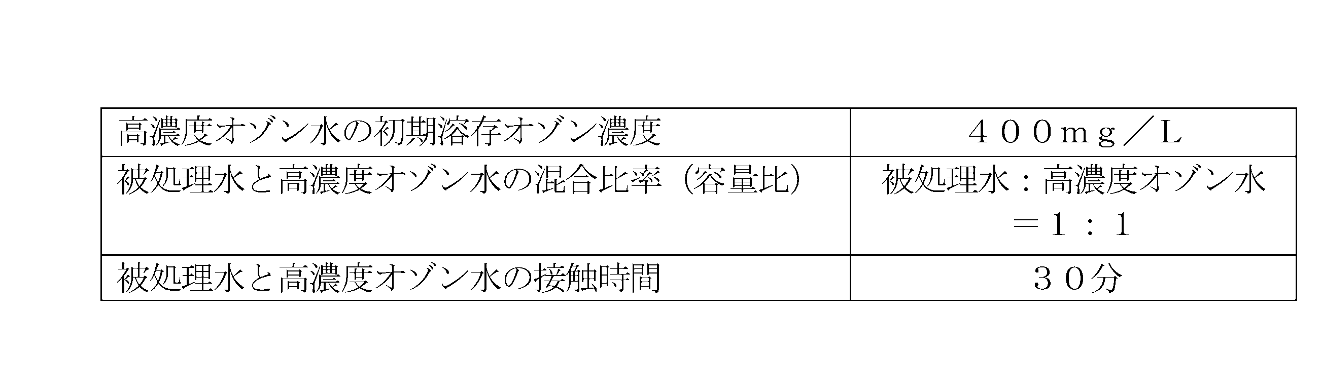
オゾン水混合処理プロセスは図8に示されたオゾン水混合槽6にて実施される。被処理水と高濃度オゾン水をオゾン水混合槽6に供給して混合させた。本処理は、バッチ方式とし、高濃度オゾン水に溶存するオゾン、さらにはこのオゾンが分解する際に生成する活性酸化種による被処理水中のPFAS含む有機物の酸化分解を図った。前述のようにPFASの有するC-F結合の分解はオゾン及び活性酸化種の酸化ポテンシャルでは困難と予想されるので、有機物のC-C、C=C等の結合を切断、分解、若しくは当該有機物の無機化を期待した。高濃度オゾン水は、前記ピュアオゾンジェネレータで製造したものを使用した。本実施例のオゾン水混合処理プロセスの条件を以下の表2に示した。
パルス放電処理プロセスは、図8のパルスプラズマ放電槽7にて実施される。パルスプラズマ放電槽7にはオゾン水混合処理プロセス(オゾン水混合槽6)の処理水(被処理水と高濃度オゾンの混合液)が供給される。曝気装置71は散気管75を介したブロア74により前記混合液を空気曝気する。電極72は、先端がパルスプラズマ放電槽7内の液面近傍の気相に配置され、パルス電源73からのパルス電圧の印加によりパルスプラズマ放電槽7との間でパルスプラズマを発生させる。前記パルスプラズマは前記液面近傍の気相を介して前記混合液に供されて当該混合液の液面に沿って流れてパルスプラズマ放電槽7を介してグラウンド(アース)に流れる。
パルス放電処理前のオゾン水接触処理の有無によるPFOSの低減効果を検証するため、比較例1として、オゾン水混合槽6にて高濃度オゾン水の代わりに純水を被処理水と混合処理した後にパルスプラズマ放電槽7でのパルス放電処理を行った。被処理水と純水との混合比率(容量比)は被処理水:純水=1:1とした。

2…被ろ過水貯留槽、20…膜ろ過装置、21…ろ過膜
3…吸着剤添加手段
4…吸着剤移送手段
5…吸着剤再生装置
6…オゾン水混合槽
7…パルスプラズマ放電槽、71…曝気装置、72…電極、73…パルス電源、74…ブロア、75…散気管
8…逆浸透膜ろ過機、81…RO膜
9…浄水場
Claims (8)
- ろ過に供される被処理物質を含有する被ろ過水を貯留する被ろ過水貯留槽と、
前記ろ過により前記被ろ過水から分離された前記被処理物質を濃縮した被処理物質濃縮排液をオゾン水と混合するオゾン水混合槽と、
前記被処理物質濃縮排液と前記オゾン水の混合液にパルスプラズマを供するパルスプラズマ放電槽と、
を備えたことを特徴とする水処理装置。 - ヒドロキシラジカルの酸化ポテンシャルよりも高い結合エネルギーを有する前記被処理物質の元素間結合を分解する前記パルスプラズマを発生可能な電源を備えたことを特徴とする請求項1に記載の水処理装置。
- 前記元素間結合は、炭素元素とフッ素元素の結合であることを特徴とする請求項2に記載の水処理装置。
- 前記被処理物質濃縮排液は、前記被ろ過水貯留槽に添加された吸着剤の再生の過程で生成されることを特徴とする請求項1に記載の水処理装置。
- 前記吸着剤は、活性炭及び/又はイオン交換樹脂であることを特徴とする請求項4に記載の水処理装置。
- 前記被処理物質濃縮排液は、活性汚泥を滞留させた前記被ろ過水貯留槽から前記被ろ過水を第一ろ過膜によるろ過に供して第一ろ過水を分離し、さらに、この第一ろ過水を当該第一ろ過膜よりも小さな孔径の第二ろ過膜によるろ過に供して生成されることを特徴とする請求項1に記載の水処理装置。
- 前記混合液は、曝気されることを特徴とする請求項1に記載の水処理装置。
- 被処理物質を含有する被ろ過水をろ過に供して当該被ろ過水から当該被処理物質を分離する工程と、
前記被処理物質を濃縮した被処理物質濃縮排液をオゾン水と混合する工程と、
前記被処理物質濃縮排液と前記オゾン水の混合液にパルスプラズマを供する工程と、
を有することを特徴とする水処理方法。
Priority Applications (2)
| Application Number | Priority Date | Filing Date | Title |
|---|---|---|---|
| EP24819364.1A EP4722167A1 (en) | 2023-06-05 | 2024-06-05 | Water treatment apparatus and water treatment method |
| JP2024533919A JP7616489B1 (ja) | 2023-06-05 | 2024-06-05 | 水処理装置及び水処理方法 |
Applications Claiming Priority (2)
| Application Number | Priority Date | Filing Date | Title |
|---|---|---|---|
| JP2023092028 | 2023-06-05 | ||
| JP2023-092028 | 2023-06-05 |
Publications (1)
| Publication Number | Publication Date |
|---|---|
| WO2024253136A1 true WO2024253136A1 (ja) | 2024-12-12 |
Family
ID=93795517
Family Applications (1)
| Application Number | Title | Priority Date | Filing Date |
|---|---|---|---|
| PCT/JP2024/020557 Ceased WO2024253136A1 (ja) | 2023-06-05 | 2024-06-05 | 水処理装置及び水処理方法 |
Country Status (3)
| Country | Link |
|---|---|
| EP (1) | EP4722167A1 (ja) |
| JP (1) | JP7616489B1 (ja) |
| WO (1) | WO2024253136A1 (ja) |
Cited By (1)
| Publication number | Priority date | Publication date | Assignee | Title |
|---|---|---|---|---|
| JP7809253B1 (ja) * | 2024-12-24 | 2026-01-30 | 三菱電機株式会社 | 二酸化炭素改質方法 |
Citations (13)
| Publication number | Priority date | Publication date | Assignee | Title |
|---|---|---|---|---|
| JP2001293478A (ja) * | 2000-04-17 | 2001-10-23 | Mitsubishi Heavy Ind Ltd | 排水処理装置 |
| JP2003062579A (ja) * | 2001-08-27 | 2003-03-04 | Kobe Steel Ltd | 液体の処理方法及びその装置 |
| JP2005111296A (ja) | 2003-10-02 | 2005-04-28 | National Institute Of Advanced Industrial & Technology | 無電解銅めっき水洗水の処理方法及びそれに使用する活性炭の再生方法 |
| JP2006297240A (ja) | 2005-04-19 | 2006-11-02 | Ebara Corp | 浄水システム |
| JP4296393B2 (ja) | 2003-06-09 | 2009-07-15 | 株式会社ササクラ | 洗浄方法及び洗浄装置 |
| JP2009255015A (ja) * | 2008-04-21 | 2009-11-05 | Sharp Corp | 水処理装置および水処理方法 |
| JP2011056451A (ja) * | 2009-09-11 | 2011-03-24 | Tokyo Institute Of Technology | 気液2相流プラズマ処理装置 |
| JP2015097975A (ja) | 2013-11-18 | 2015-05-28 | 株式会社セイデン | 液面プラズマ放電を利用した水処理装置 |
| JP2016059853A (ja) * | 2014-09-17 | 2016-04-25 | 前澤工業株式会社 | 水処理方法及び装置 |
| JP2018038955A (ja) | 2016-09-07 | 2018-03-15 | 野村マイクロ・サイエンス株式会社 | 水処理装置及び水処理方法 |
| US20180339921A1 (en) * | 2017-05-24 | 2018-11-29 | Clarkson University | Plasma-based methods and systems for treating waters with high electrical conductivity and/or low surface tension |
| JP6702514B1 (ja) | 2018-11-30 | 2020-06-03 | 株式会社明電舎 | 酸化膜形成装置 |
| CN112897775A (zh) * | 2021-01-20 | 2021-06-04 | 常熟理工学院 | 一种含氟有机废液处理方法 |
-
2024
- 2024-06-05 EP EP24819364.1A patent/EP4722167A1/en active Pending
- 2024-06-05 WO PCT/JP2024/020557 patent/WO2024253136A1/ja not_active Ceased
- 2024-06-05 JP JP2024533919A patent/JP7616489B1/ja active Active
Patent Citations (13)
| Publication number | Priority date | Publication date | Assignee | Title |
|---|---|---|---|---|
| JP2001293478A (ja) * | 2000-04-17 | 2001-10-23 | Mitsubishi Heavy Ind Ltd | 排水処理装置 |
| JP2003062579A (ja) * | 2001-08-27 | 2003-03-04 | Kobe Steel Ltd | 液体の処理方法及びその装置 |
| JP4296393B2 (ja) | 2003-06-09 | 2009-07-15 | 株式会社ササクラ | 洗浄方法及び洗浄装置 |
| JP2005111296A (ja) | 2003-10-02 | 2005-04-28 | National Institute Of Advanced Industrial & Technology | 無電解銅めっき水洗水の処理方法及びそれに使用する活性炭の再生方法 |
| JP2006297240A (ja) | 2005-04-19 | 2006-11-02 | Ebara Corp | 浄水システム |
| JP2009255015A (ja) * | 2008-04-21 | 2009-11-05 | Sharp Corp | 水処理装置および水処理方法 |
| JP2011056451A (ja) * | 2009-09-11 | 2011-03-24 | Tokyo Institute Of Technology | 気液2相流プラズマ処理装置 |
| JP2015097975A (ja) | 2013-11-18 | 2015-05-28 | 株式会社セイデン | 液面プラズマ放電を利用した水処理装置 |
| JP2016059853A (ja) * | 2014-09-17 | 2016-04-25 | 前澤工業株式会社 | 水処理方法及び装置 |
| JP2018038955A (ja) | 2016-09-07 | 2018-03-15 | 野村マイクロ・サイエンス株式会社 | 水処理装置及び水処理方法 |
| US20180339921A1 (en) * | 2017-05-24 | 2018-11-29 | Clarkson University | Plasma-based methods and systems for treating waters with high electrical conductivity and/or low surface tension |
| JP6702514B1 (ja) | 2018-11-30 | 2020-06-03 | 株式会社明電舎 | 酸化膜形成装置 |
| CN112897775A (zh) * | 2021-01-20 | 2021-06-04 | 常熟理工学院 | 一种含氟有机废液处理方法 |
Non-Patent Citations (2)
| Title |
|---|
| S. HORIKOSHIS. SATOM. ABEN. SERPONE: "A novel liquid plasma AOP device integrating microwaves and ultrasounds and its evaluation in defluorinating perfluorooctanoic acid in aqueous media", ULTRASON. SONOCHEM., vol. 18, 2011, pages 938 - 942 |
| TAKANORI IIJIMARYUTARO MAKISETAKAAKI MURATA: "OH Radical Generator for Waste Water Treatment Containing Recalcitrant Organic Matter", TOSHIBA REVIEW, vol. 61, no. 8, 2006 |
Cited By (1)
| Publication number | Priority date | Publication date | Assignee | Title |
|---|---|---|---|---|
| JP7809253B1 (ja) * | 2024-12-24 | 2026-01-30 | 三菱電機株式会社 | 二酸化炭素改質方法 |
Also Published As
| Publication number | Publication date |
|---|---|
| JPWO2024253136A1 (ja) | 2024-12-12 |
| JP7616489B1 (ja) | 2025-01-17 |
| EP4722167A1 (en) | 2026-04-08 |
Similar Documents
| Publication | Publication Date | Title |
|---|---|---|
| CN1192817C (zh) | 用于制造含有溶解的臭氧的水的设备 | |
| JP2677468B2 (ja) | 純水の製造方法及び装置 | |
| US11827537B2 (en) | System and method for removal of recalcitrant organic compounds from water | |
| JP2007509740A (ja) | 酸化および膜濾過により水性廃液を精製する装置および方法 | |
| JP7283088B2 (ja) | 水処理方法および水処理装置 | |
| WO2019159197A1 (en) | Method and apparatus for regenerating a working salt solution in salt purification | |
| JP7616489B1 (ja) | 水処理装置及び水処理方法 | |
| JP2006192378A (ja) | 難分解性物質含有水の処理方法 | |
| US10493423B2 (en) | Purification treatment method of liquid containing harmful substance, and purification treatment device of liquid containing harmful substance for carrying out said method | |
| JPH09159798A (ja) | 泡除染および除染廃液処理の方法 | |
| JPH1199394A (ja) | 水中の有機物除去方法 | |
| JP2024180793A (ja) | 水処理装置及び水処理方法 | |
| JPH10202296A (ja) | 超純水製造装置 | |
| RU2636076C2 (ru) | Способ фотохимической очистки воды и устройство для его осуществления | |
| JP3928484B2 (ja) | 機能水の回収方法 | |
| JP3766298B2 (ja) | 排水処理方法及び装置 | |
| JP2000279977A (ja) | 流体処理方法及び流体処理装置 | |
| JP2024099506A (ja) | 水処理方法および水処理装置 | |
| CN215208865U (zh) | 一种快速去除氨氮及总磷的小型污水处理装置 | |
| JPH0338297A (ja) | トリクロロエチレン及びテトラクロロエチレン汚染水の処理方法 | |
| JPH05305297A (ja) | 有機物含有酸性排水の処理装置 | |
| JPH0938671A (ja) | 水処理方法及び水処理装置 | |
| JPS60118283A (ja) | 有機溶剤含有排水の処理方法 | |
| CN116322947B (zh) | 超纯水制造系统及超纯水制造方法 | |
| JP2001170688A (ja) | 有機物とマンガンイオンを含む水の処理装置 |
Legal Events
| Date | Code | Title | Description |
|---|---|---|---|
| ENP | Entry into the national phase |
Ref document number: 2024533919 Country of ref document: JP Kind code of ref document: A |
|
| 121 | Ep: the epo has been informed by wipo that ep was designated in this application |
Ref document number: 24819364 Country of ref document: EP Kind code of ref document: A1 |
|
| WWE | Wipo information: entry into national phase |
Ref document number: 2024819364 Country of ref document: EP |
|
| NENP | Non-entry into the national phase |
Ref country code: DE |
|
| ENP | Entry into the national phase |
Ref document number: 2024819364 Country of ref document: EP Effective date: 20260105 |
|
| ENP | Entry into the national phase |
Ref document number: 2024819364 Country of ref document: EP Effective date: 20260105 |
|
| ENP | Entry into the national phase |
Ref document number: 2024819364 Country of ref document: EP Effective date: 20260105 |
|
| WWP | Wipo information: published in national office |
Ref document number: 2024819364 Country of ref document: EP |