WO2024253072A1 - 鋳型作製方法、鋳型作製システム、情報処理装置、情報処理システム、情報処理方法、コンピュータプログラム、および記録媒体 - Google Patents
鋳型作製方法、鋳型作製システム、情報処理装置、情報処理システム、情報処理方法、コンピュータプログラム、および記録媒体 Download PDFInfo
- Publication number
- WO2024253072A1 WO2024253072A1 PCT/JP2024/020267 JP2024020267W WO2024253072A1 WO 2024253072 A1 WO2024253072 A1 WO 2024253072A1 JP 2024020267 W JP2024020267 W JP 2024020267W WO 2024253072 A1 WO2024253072 A1 WO 2024253072A1
- Authority
- WO
- WIPO (PCT)
- Prior art keywords
- mold
- information
- detection means
- mold material
- sensor
- Prior art date
- Legal status (The legal status is an assumption and is not a legal conclusion. Google has not performed a legal analysis and makes no representation as to the accuracy of the status listed.)
- Ceased
Links
Images











Classifications
-
- B—PERFORMING OPERATIONS; TRANSPORTING
- B22—CASTING; POWDER METALLURGY
- B22C—FOUNDRY MOULDING
- B22C1/00—Compositions of refractory mould or core materials; Grain structures thereof; Chemical or physical features in the formation or manufacture of moulds
- B22C1/16—Compositions of refractory mould or core materials; Grain structures thereof; Chemical or physical features in the formation or manufacture of moulds characterised by the use of binding agents; Mixtures of binding agents
- B22C1/18—Compositions of refractory mould or core materials; Grain structures thereof; Chemical or physical features in the formation or manufacture of moulds characterised by the use of binding agents; Mixtures of binding agents of inorganic agents
-
- B—PERFORMING OPERATIONS; TRANSPORTING
- B22—CASTING; POWDER METALLURGY
- B22C—FOUNDRY MOULDING
- B22C1/00—Compositions of refractory mould or core materials; Grain structures thereof; Chemical or physical features in the formation or manufacture of moulds
- B22C1/16—Compositions of refractory mould or core materials; Grain structures thereof; Chemical or physical features in the formation or manufacture of moulds characterised by the use of binding agents; Mixtures of binding agents
- B22C1/20—Compositions of refractory mould or core materials; Grain structures thereof; Chemical or physical features in the formation or manufacture of moulds characterised by the use of binding agents; Mixtures of binding agents of organic agents
- B22C1/22—Compositions of refractory mould or core materials; Grain structures thereof; Chemical or physical features in the formation or manufacture of moulds characterised by the use of binding agents; Mixtures of binding agents of organic agents of resins or rosins
-
- B—PERFORMING OPERATIONS; TRANSPORTING
- B22—CASTING; POWDER METALLURGY
- B22C—FOUNDRY MOULDING
- B22C19/00—Components or accessories for moulding machines
- B22C19/04—Controlling devices specially designed for moulding machines
-
- B—PERFORMING OPERATIONS; TRANSPORTING
- B22—CASTING; POWDER METALLURGY
- B22C—FOUNDRY MOULDING
- B22C9/00—Moulds or cores; Moulding processes
-
- B—PERFORMING OPERATIONS; TRANSPORTING
- B22—CASTING; POWDER METALLURGY
- B22C—FOUNDRY MOULDING
- B22C9/00—Moulds or cores; Moulding processes
- B22C9/02—Sand moulds or like moulds for shaped castings
Definitions
- the present invention relates to a method for making a casting mold, a casting mold making system, an information processing device, an information processing system, an information processing method, a computer program, and a recording medium.
- Sand molds are widely used as casting molds, and generally, after filling the master mold with mold material and hardening the mold, a demolding process is always included. In the demolding process, it is necessary to carefully remove the mold from the master mold, but if the mold is not strong enough at the time of demolding, it will break, deform, or change in dimensions, and an appropriate mold will not be obtained. On the other hand, in terms of mold productivity, it is required to demold the mold as quickly as possible, so sometimes the mold is demolded when its strength is insufficient. To prevent this from happening, a test piece is made separately using the mixed sand used to make the mold, and its strength is measured. However, because the shape is different from the actual product mold, although it can be used as a reference, it does not necessarily match the strength of the actual mold.
- Patent Document 1 describes an example of a technology that measures the strength of a mold before it is demolded and prevents the mold from collapsing or warping due to demolding.
- the mold strength measuring device described in Patent Document 1 obtains information about the strength of a mold that has a product surface and a back surface opposite the product surface.
- This mold strength measuring device includes a cutting tool and a probe.
- the cutting tool forms a bottomed hole in the mold that extends from the back surface toward the product surface.
- the measurement probe can be inserted into the hole and measures the reaction force received from the bottom of the hole.
- the first aspect relates to a method of making a template.
- the method of making a template according to the first aspect comprises the steps of: A detection means for generating hardening state information capable of identifying a hardening state of a mold material is disposed in a master for producing a mold before the mold material is filled, so as to face the mold material when the mold material is filled; Then, the mold material is filled into the interior of the master. obtaining the curing state information during curing of the mold material; The method includes determining, using the obtained cured state information, that it is time to demold the mold, and then demolding the mold.
- An information processing device includes: a receiving unit that receives hardening state information capable of identifying a hardening state of the mold material from a detection means that is arranged before the mold material is filled into a master model for producing a mold so as to face the mold material when the mold material is filled into the master model; A determination unit that repeatedly determines whether or not it is time to demold the mold using the received curing state information; and an output unit that outputs, when it is determined that the timing for demolding has arrived, information indicating that the timing for demolding has arrived.
- a third aspect relates to an information processing method implemented by one or more computers.
- An information processing method comprises: One or more computers receiving, from a detection means arranged in advance before filling the mold material, information on a hardening state capable of identifying a hardening state of the mold material, so as to face the mold material when the mold material is filled into a master for producing a mold; Using the received curing state information, it is repeatedly determined whether or not it is time to demold the mold; When it is determined that the timing for demolding has arrived, information indicating that the timing for demolding has arrived is output.
- a fourth aspect relates to a template making system.
- a mold making system comprises: a master mold having a detection means for generating hardening state information capable of identifying a hardening state of a mold material, the detection means being disposed so as to face the mold material when the mold material is filled;
- An information processing device includes: a receiving unit that receives, from the detection means, hardening state information that can identify the hardening state of the mold material; A determination unit that repeatedly determines whether or not it is time to demold the mold using the received curing state information; and an output unit that outputs information indicating that the timing for removing the mold has arrived when it is determined that the timing for removing the mold has arrived, After the mold material is filled into the interior of the master, The information processing device, obtaining, during hardening of the mold material, hardening state information from a detection means for generating hardening state information capable of identifying a hardening state of the mold material; Using the obtained curing state information
- Another aspect of the present invention may be a program for causing at least one computer to execute the method of the third aspect, or a computer-readable recording medium having such a program recorded thereon.
- This recording medium includes a non-transitory tangible medium.
- the computer program includes computer program code which, when executed by a computer, causes the computer to carry out the control method on an information processing device.
- the various components of the present invention do not necessarily have to be independent entities, but may be formed as a single member by multiple components, one component may be formed from multiple components, one component may be part of another component, or part of one component may overlap with part of another component, etc.
- the multiple steps of the method and computer program of the present invention are not limited to being executed at different times. Therefore, a step may occur while another step is being executed, or the execution timing of a step may overlap in part or in whole with the execution timing of another step, etc.
- FIG. 2 is a diagram for explaining a casting manufacturing process.
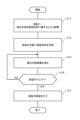
- 1 is a flowchart showing the steps of a mold fabrication method according to an embodiment.
- 1A and 1B are diagrams illustrating a first example of an arrangement of a detection means in a mold production method according to an embodiment.
- FIG. 4 is a diagram showing a modification of the first arrangement example in FIG. 3 .
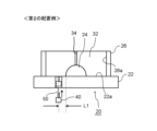
- FIG. 13 is a diagram showing a second example of the arrangement of the detection means in the mold production method according to the embodiment.
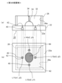
- FIG. 13 is a diagram showing a third example of the arrangement of the detection means in the mold production method according to the embodiment.
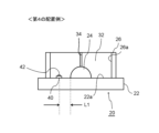
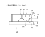
- FIG. 13 is a diagram showing a fourth example of the arrangement of the detection means in the mold production method according to the embodiment.
- FIG. 1 is a flowchart showing the steps of a mold fabrication method according to an embodiment.
- 1A and 1B are diagrams illustrating a first example of an arrangement of a detection means in a mold production method according to an embodiment.
- FIG. 8 is a diagram showing a modification of the fourth arrangement example in FIG. 7 .
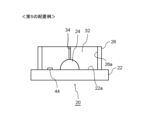
- FIG. 13 is a diagram showing a fifth example of the arrangement of the detection means in the mold production method according to the present embodiment.
- FIG. 13 is a diagram showing a sixth example of the arrangement of the detection means in the mold production method according to the embodiment.
- FIG. 2 is a schematic diagram showing a mold manufacturing apparatus.
- FIG. 2 is a diagram for explaining a casting manufacturing process according to an embodiment.
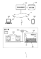
- 1 is a diagram conceptually illustrating a system configuration of an information processing system according to an embodiment.
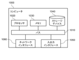
- FIG. 2 is a block diagram illustrating a hardware configuration of a computer that realizes an information processing device.
- 1 is a functional block diagram showing a logical configuration of an information processing apparatus according to an embodiment.
- FIG. 4 is a diagram illustrating an example of a data structure of sensor information.
- FIG. 13 is a diagram illustrating an example of a data structure of mold information.
- FIG. 4 is a diagram illustrating an example of a data structure of sensor installation information.
- FIG. 13 is a diagram illustrating an example of a data structure of curing state information.
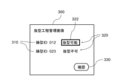
- FIG. 13 is a diagram showing an example of an output screen.
- 5 is a flowchart illustrating an example of the operation of the information processing device according to the embodiment.
- 22 is a flowchart showing details of the output process in step S105 of FIG. 21 .
- 1 is a functional block diagram showing a logical configuration of an information processing apparatus according to an embodiment.
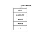
- FIG. 13 is a diagram illustrating an example of a data structure of die history information.
- FIG. 5 is a flowchart illustrating an example of the operation of the information processing device according to the embodiment.
- 13A and 13B are diagrams illustrating an example of the arrangement of a detection means in a mold production method according to another embodiment.
- FIG. 10 is a diagram showing a specific example of installation of sensors arranged in the fifth arrangement example of FIG. 9 .
- 28A to 28C are diagrams showing examples of other shapes of the container used in the installation example of FIG. 27.
- Patent Document 1 the strength of the mold is measured by inserting a measurement probe from the back surface of the mold opposite the product surface toward the product surface.
- Patent Document 1 also describes that by making the depth of the hole at least half the distance between the back surface and the product surface, it is possible to measure the strength of the "portion close to" the product surface of the mold, which affects the performance of the mold. For this reason, the technology described in Patent Document 1 cannot measure the strength of the product surface side of the mold.
- the mold shape is large in size, thickness, or height, the hardening of the product surface side of the mold is delayed compared to the outside, resulting in insufficient strength on the product surface side inside the mold, and it is not possible to prevent the mold on the product surface side from collapsing or deforming when demolded.
- the product side is the most disadvantageous side for the evaporation of moisture and solvents and is usually the most difficult to harden.
- the evaporation of moisture and solvents varies depending on the individual mold shape, so even if the same hardening conditions are set, the hardening state of each product surface will differ for each mold and may also differ depending on the location.
- the weakest parts are often the ones that break or deform when the mold is removed, so understanding the strength of the product surface and being able to determine whether the mold can be removed at the right time can help reduce defects and improve mold productivity.
- the product surface when using acid-curing furan resin, acid-curing phenolic resin, or ester-curing alkaline phenolic resin, which cure through a dehydration condensation reaction, among other self-hardening molds, the product surface, where water is less likely to evaporate, cures particularly slowly, while the back surface (opposite the product surface), which is in contact with the outside air and where water is more likely to evaporate, cures quickly.
- the product surface often remains uncured because the cure is judged only by the hardness of the back surface, which can be measured from the outside, and there is often a surplus of time before the mold can be removed.
- the difference in the degree of cure between the back surface and the product surface increases the higher the mold is, so in the case of self-hardening molds, which are used to manufacture molds of various heights, determining the time when the mold can be removed is even more difficult.
- This disclosure has been made in consideration of the above circumstances, and its purpose is to provide a technology that can determine the optimal timing for demolding in terms of the strength of the product surface inside the mold, which is difficult to judge from the outside of the mold, regardless of the shape or size of the mold.
- the above aspects provide a technology that can determine the optimal timing for demolding based on the strength of the product surface inside the mold, which is difficult to judge from the outside, regardless of the mold's shape or size.
- acquisition includes at least one of the following: the device itself goes to retrieve data or information stored in another device or storage medium (active acquisition), and the device itself inputs data or information output from another device (passive acquisition).
- active acquisition include making a request or inquiry to another device and receiving a reply, and accessing and reading information from another device or storage medium.
- passive acquisition is receiving information that is distributed (or transmitted, push notification, etc.).
- acquisition may mean selecting and acquiring data or information from received data or information, or selecting and receiving distributed data or information.
- FIG. 1 is a diagram for explaining the casting manufacturing process.
- the casting manufacturing process includes a mold making step S1, a mold stripping step S2, and a molten metal pouring step S3.
- refractory particles such as silica sand or artificial sand are charged from a hopper 210 into a kneader 220.
- a binder and a hardener are also charged into the kneader 220.
- the mold material 30, which is a mixture of refractory particles, a binder, and a hardener, is poured from the mixer 220 into the master 20, which is made up of the base plate 22, the product portion 24, and the molding flask 26, to create a sand mold.
- the base plate 22, the product portion 24, and the molding flask 26 are, for example, wooden molds.
- the refractory particles may be, for example, silica sand, zircon, chromite, olivine, alumina, synthetic mullite, or other single or mixed sand, and may be either new sand or recycled sand.
- recycled sand is refractory particles that have been used in casting molds and have been regenerated by mechanical polishing, roasting, or other methods.
- a self-hardening resin when used, it is useful because the strength increases over time and the mold can be removed when the specified mold strength is reached, thereby increasing mold productivity. It is particularly useful for organic self-hardening resins such as furan resin, an acid-hardening resin that hardens through a dehydration condensation reaction in which the presence of water or solvents hinders the progress of the hardening reaction, phenol resin, and alkali phenol resin, an ester-hardening resin, as well as inorganic self-hardening resins such as water glass.
- organic self-hardening resins such as furan resin, an acid-hardening resin that hardens through a dehydration condensation reaction in which the presence of water or solvents hinders the progress of the hardening reaction, phenol resin, and alkali phenol resin, an ester-hardening resin, as well as inorganic self-hardening resins such as water glass.
- a hardener is a catalyst or reactive component that causes a hardening reaction in the binder.
- the binder is an organic self-hardening resin
- a liquid hardener is usually used.
- an acidic hardening catalyst containing sulfuric acid, phosphoric acid, or organic sulfonic acid is used, and when using alkaline phenol resin, an organic ester can be used as the hardener, whose hardening speed can be adjusted depending on the degree of hydrolysis and the level of compatibility.
- an organic ester can be used as the hardener, whose hardening speed can be adjusted depending on the degree of hydrolysis and the level of compatibility.
- the molding sand 32 is removed from the master 20 by the demolding device 240 to create the mold 10 (e.g., upper mold 10a and lower mold 10b).
- the created upper mold 10a and lower mold 10b are combined and used as the mold 10 in the next pouring process S3.
- the demolding process S2 does not necessarily have to use the demolding device 240, and the worker may manually perform the demolding.
- molten metal 250 is poured into the mold 10, which is made by matching the upper and lower dies 10a and 10b. After the molten metal cools and solidifies, it is removed from the mold 10 as the product 260. The sand in the mold 10 is recycled and can be reused in the molding process S1 as recycled sand 270.
- the binder in the molding sand 32 filled with the mold material 30 in the master 20 undergoes a polymerization reaction with the hardener, and the molding sand 32 hardens.
- the hardening is further accelerated by the evaporation of water and solvent from the mold.
- the molding sand 32 is demolded from the master 20 to produce the mold 10.
- the mold production method according to this embodiment provides a method for identifying the appropriate timing for demolding the molding sand 32 from the master 20.
- FIG. 2 is a flow chart showing the steps of the mold fabrication method according to this embodiment.
- the mold making method according to the present embodiment includes arranging a detection means in the master 20 for making the mold 10 before filling the mold material 30 so that the detection means faces the mold material 30 when the mold material 30 is filled (step S11), filling the master 20 with the mold material 30 (step S13), obtaining hardening state information generated by the detection means while the molding sand 32 made of the mold material 30 is hardening (step S15), and using the obtained hardening state information, if it is determined that it is time to release the mold 10 (YES in step S16), the molding sand 32 is released to make the mold 10 (step S17). Note that if it is not determined in step S16 that it is time to release the mold 10 (NO in step S16), the process returns to step S15.
- the master 20 may be composed of a base plate 22, a product portion 24, and a molding flask 26, or may be one piece.
- the master for making the core may be composed of two molds that are fitted together facing each other to form a space in the center having the shape of the core.
- the product portion 24 is, for example, a wooden model that forms the outer shape of the casting product 260 to be cast.
- the product portion 24 is placed on the base plate 22 in the space formed by the base plate 22 and the molding flask 26, which is filled with the mold material 30.
- the detection means and the generated curing state information will be described below.
- the detection means generates hardened state information capable of identifying the hardened state of the mold material 30 filled in the space of the master 20.
- the mold material 30 is a mixture of refractory particles, a hardener, and a binder.
- the detection means is a strength sensor that contacts the surface of molding sand 32 made of mold material 30 and measures the strength (e.g., pressure resistance, hardness, etc.) of the molding sand 32 during hardening.
- the hardening state information generated by the strength sensor is a value indicating the hardness of the mold material at the location where the sensor is installed.
- At least one strength sensor is placed on at least one of the base plate 22 and the molding flask 26 before the mold material 30 is filled into the master 20.
- strength sensors can be used. Examples of strength sensors include hardness sensors such as actuators with load cells (strain gauges). These strength sensors can be used to measure strength directly. Alternatively, only a load cell can be installed as a strength sensor, and some external force can be applied and the reaction force can be measured using this load cell. Alternatively, hardening state information can be generated using a position sensor (contact displacement sensor) rather than a sensor that directly measures strength.
- hardness sensors such as actuators with load cells (strain gauges). These strength sensors can be used to measure strength directly. Alternatively, only a load cell can be installed as a strength sensor, and some external force can be applied and the reaction force can be measured using this load cell. Alternatively, hardening state information can be generated using a position sensor (contact displacement sensor) rather than a sensor that directly measures strength.
- a constant measurement pressure is set and a sensor head is brought into contact with the surface of the molding sand 32, and a certain amount of displacement or more that accompanies the hardening of the molding sand 32 is detected to determine the strength of the molding sand 32, and the result can be used as hardening state information.
- the detection means may generate the hardening state information using a sensor that measures the electrical conductivity, dielectric constant, or temperature of molding sand 32 made of mold material 30. Using at least one of the electrical conductivity, dielectric constant, and temperature measured by the sensor, the hardening state of molding material 30 of molding sand 32 during hardening can be identified. Specifically, the detection means identifies the hardening state and generates the hardening state information based on a change in at least one of the electrical conductivity, dielectric constant, and temperature detected by the sensor. This is particularly effective for furan resin, whose hardening reaction is an exothermic reaction.
- the detection means may be an ultrasonic or sonic sensor.
- the strength may be determined by measuring the conduction speed and strength of the reflected waves and comparing them with previously obtained conduction speed and strength at the time of hardening. In this case, it is possible to determine at least the strength of the binder contained in the mold material 30.
- step S11 Arrangement of detection means>
- the detection means is disposed on the inner surface of at least one of the bottom plate 22 and the molding flask 26. Therefore, the timing of demolding can be determined based on information on the hardened state of the inner surface of the product side of the master mold made of the molding sand 32.
- the method of disposing the detection means in step S11 will be described below with a specific example.
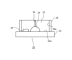
- ⁇ First Arrangement Example> 3 is a diagram showing a first example of the arrangement of the detection means in the mold making method according to the present embodiment.
- Fig. 3 is a cross-sectional view in a direction perpendicular to the bottom plate 22 of the molding sand 32 in which the mold material 30 has been filled inside the master 20 in step S13.
- At least a portion of the detection means is built into at least one of the bottom plate 22 and the molding flask 26.
- the detection means is, for example, a sensor 40 that has a sensor tip 42 that contacts the surface of molding sand 32 made of mold material 30, measures the strength of molding sand 32 during hardening, and outputs a value indicating the hardness of molding sand 32.
- the sensor 40 is built into the base plate 22 or the molding flask 26 so that the sensor tip 42 faces the surface of molding sand 32.
- the detection means is built into at least one of the bottom plate 22 and the flask 26, so the portion of the detection means that abuts or is embedded in the molding sand 32 can be minimized. This allows the mold 10 to be maintained at high quality.
- the measurement value of the sensor 40 may be transmitted to the information processing device 100 via a communication device 202 described later, either wired or wirelessly.
- the sensor 40 is embedded in the bottom plate 22.
- the sensor tip 42 is positioned so as to be flush with the upper surface 22a of the bottom plate 22 or higher than the upper surface 22a.
- the sensor 40 is a detection means capable of generating information on the hardened state of the molding sand 32 in a non-contact manner
- the sensor tip 42 may be positioned so as to be lower than the upper surface 22a of the bottom plate 22.
- the detection means also includes the vertically upward portion of the sensor tip 42 between the upper surface of the sensor tip 42 and the upper surface 22a of the bottom plate 22.
- the installation position of the sensor 40 can be indicated, for example, by the distance L1 from the outer edge of the product portion 24 to the center of the sensor tip 42 of the sensor 40. However, the installation position of the sensor 40 can also be indicated by something other than the distance L1.
- FIG. 4 is a diagram showing a modification of the first arrangement example of FIG. As shown in FIG. 4, in an example in which the sensor 40 is built into the molding flask 26, the installation position of the sensor 40 may be indicated by a distance L2 in the height direction from the upper surface 22a of the bottom plate 22 to the center of the sensor 40.
- the sensor 40 is embedded in the flask 26.
- the sensor tip 42 is positioned so that it is flush with the inner surface 26a of the flask 26 or is closer to the molding sand 32 than the inner surface 26a.
- the sensor 40 is a detection means capable of generating information on the hardened state of the molding sand 32 without contact
- the sensor tip 42 may be positioned outside the inner surface 26a of the flask 26, that is, away from the surface of the molding sand 32.
- the position of the sensor 40 can be represented by two-dimensional coordinates on the top surface 22a of the bottom plate 22 when viewed in a plan view.
- the position of the sensor 40 can be represented by three-dimensional coordinates in the space formed by the bottom plate 22 and the molding flask 26.
- the location information indicating the installation position of the sensor 40 is stored in the storage device 120 of the information processing device 100 of the embodiment described below, and is used for information processing by the information processing device 100.
- the location information of the sensor 40 can be input by user operation, for example, on an operation screen including a UI (User Interface) that accepts user operations of the information processing device 100.
- the installation position of the sensor 40 may be a value that is preset at the time of design, or may be a value measured from the installation position of the sensor 40 installed by a worker on-site.
- the position information of the sensor 40 stored in the storage device 120 of the information processing device 100 may be displayed on the display of a mobile terminal 282 (described later) used by the worker.
- the worker can place the sensor 40 on the bottom plate 22 or the molding flask 26 while checking the position information of the sensor 40.
- each sensor 40 When multiple sensors 40 are installed as detection means, it is preferable to place each sensor 40 at a different distance L1 or distance L2, for example.
- the mold material 30 contains a dehydration condensation binder, it hardens as moisture escapes from the mold material 30, and so the hardened state differs between the inside and outside of the molding sand 32. Also, depending on the shape of the molding sand 32, the hardened state differs between areas where the molding sand 32 is thick and areas where it is thin. Therefore, it is preferable to place multiple sensors 40 at different positions (at different distances L1 or different distances L2) to obtain hardened state information at different positions.
- ⁇ Second Arrangement Example> 5 is a diagram showing a second example of the arrangement of the detection means in the mold making method according to the present embodiment.
- Fig. 5 is a cross-sectional view in a direction perpendicular to the bottom plate 22 of the molding sand 32 filled with the mold material 30 inside the master 20 in step S13.
- a hole capable of housing and moving the detection means is disposed in the bottom plate 22 or the flask 26.
- at least one hole 50 capable of housing and moving the detection means (sensor 40) is formed in at least one of the bottom plate 22 and the flask 26.
- step S11 at least a part (sensor tip 42) of the detection means (sensor 40) is exposed from the hole 50 at least at the timing when the hardening state information should be generated.
- the sensor tip 42 is positioned so that it is flush with the upper surface 22a of the bottom plate 22 or higher than the upper surface 22a. However, if the sensor 40 is a detection means capable of generating information on the hardened state of the molding sand 32 in a non-contact manner, the sensor tip 42 may be positioned so that it is lower than the upper surface 22a of the bottom plate 22.
- the installation position of the sensor 40 can be indicated, for example, by the distance L1 from the outer end of the product portion 24 to the center of the hole 50.
- the installation position of the sensor 40 may be indicated by the height direction distance L2 from the upper surface 22a of the bottom plate 22 to the center of the sensor 40.
- the position of the sensor 40 may be indicated by the two-dimensional coordinates of the center position of the sensor 40 on the upper surface 22a when the bottom plate 22 is viewed in plan.
- the position of the sensor 40 may be indicated by the three-dimensional coordinates of the space formed by the bottom plate 22 and the molding flask 26.
- holes 50 in order to obtain information on the curing state at different positions, it is preferable to form holes 50 at different positions (positions at different distances L1 or L2) and place sensors 40 in the holes 50.
- multiple holes 50 are formed in advance in the bottom plate 22 or the molding flask 26, and the detection means can be inserted into the holes 50 when making measurements, so that measurements at multiple locations can be taken with at least one detection means. Also, measurements can be taken with different detection means for each location, improving the accuracy of the hardening state information.
- FIGS. 6A and 6B are diagrams showing a third example of the arrangement of the detection means in the mold making method according to the present embodiment.
- Fig. 6A is a vertical cross-sectional view of the molding sand 32 filled with the mold material 30 in the master 20 in step S13, relative to the bottom plate 22.
- Fig. 6B is a horizontal cross-sectional view of the upper surface 22a of the bottom plate 22, in a plan view of the molding sand 32 from above.
- a plurality of sensors 40 are built into the bottom plate 22 .
- the bottom plate 22 includes, inside the molding flask 26, a product area 60 (area indicated by hatching in the figure) where the product portion 24 is formed, and a non-product area 62 (area indicated by dots in the figure) which is the area other than the product portion 24.
- step S11 the sensor 40 is installed in a portion (non-product area 62) of the master mold that is different from the product portion 24 (product area 60) that corresponds to the casting product to be manufactured in the mold 10.
- six sensors 40 are disposed at positions indicated by L11, L12, L13, and L14.
- the position of each sensor 40 can be indicated by the center position of the sensor 40 being two-dimensional coordinates on the upper surface 22a when the bottom plate 22 is viewed in plan, as shown in the figure.
- ⁇ Fourth Arrangement Example> 7 is a diagram showing a fourth example of the arrangement of the detection means in the mold making method according to the present embodiment.
- Fig. 7 is a cross-sectional view in a direction perpendicular to the bottom plate 22 of the molding sand 32 filled with the mold material 30 inside the master 20 in step S13.
- the detection means is placed on the upper surface 22a of the bottom plate 22. More specifically, in step S11, the sensor 40 is arranged on the upper surface 22a of the bottom plate 22 so that at least the sensor tip 42 of the sensor 40 abuts against the molding sand 32.
- the sensor 40 is installed at a position where the distance from the outer end of the product portion 24 to the center of the sensor 40 is L1.
- the senor 40 can be placed on the master without any special processing, and there is a high degree of freedom in where it can be placed. Furthermore, it is only necessary to prepare a certain number of sensors for each molding line, so it can be introduced at low cost. Also, if the sensor is not firmly fixed to the master, and is removed by the casting mold when it is removed, it is possible to continue measuring after removal of the mold.
- FIG. 8 is a diagram showing a modification of the fourth arrangement example in FIG. 8, the sensor 40 may be attached to the inner surface 26a of the molding flask 26 so that at least the sensor tip 42 is in contact with the molding sand 32.
- the sensor 40 is installed at a position where the distance from the upper surface 22a of the bottom plate 22 to the center of the sensor 40 is L2 in the height direction.
- ⁇ Fifth Arrangement Example> 9 is a diagram showing a fifth example of the arrangement of the detection means in the mold making method according to the present embodiment.
- Fig. 9 is a cross-sectional view in a direction perpendicular to the bottom plate 22 of the molding sand 32 filled with the mold material 30 inside the master 20 in step S13.
- the detection means includes a sensor 44 that measures the electrical conductivity, dielectric constant, or temperature of the molding sand 32 made of the mold material 30.
- the sensor 44 is provided on the upper surface 22a of the bottom plate 22. At least one of the electrical conductivity, dielectric constant, and temperature measured by the sensor 44 is used to identify the hardened state of the molding material 30 of the molding sand 32 during hardening. Specifically, the detection means identifies the hardened state based on a change in at least one of the electrical conductivity, dielectric constant, and temperature measured by the sensor 44, and generates hardened state information.
- the relationship between the changes in electrical conductivity and dielectric constant and the hardening state should be determined in advance using test pieces or similar to obtain data showing this relationship between the changes in electrical conductivity and dielectric constant and the hardening state.
- the data showing the relationship between the changes in electrical conductivity and dielectric constant and the hardening state will vary depending on the type of sand, temperature, binder and hardener used, so it is preferable to specify the data in advance taking these factors into account.
- the progress of hardening can be determined based on the temperature change of the mold material 30. Although it depends on the type of binder, if the hardening reaction of the mold material 30 is an exothermic reaction, heat is generated as the hardening reaction progresses, and the heat evaporates and dries the moisture, accelerating hardening.
- the hardened state of the mold material 30 can be determined by the temperature change of the mold material 30 due to this exothermic reaction. For example, at the beginning of casting, the temperature of the mold material 30 tends to rise due to the exothermic reaction of the mold material 30, but as the exothermic reaction subsides over time, the temperature of the mold material 30 becomes constant and then decreases over time.
- the hardened state of the mold material 30 can be determined by observing the temperature change of the mold material 30. At this time, it is preferable to measure the temperature of the molding sand before mixing, the air temperature, and the temperature of the mold material immediately after mixing. By observing both these temperatures and the temperature change of the mold material, the hardened state can be determined with higher accuracy.
- the temperature change of the mold also varies depending on the material of the master model, its thermal properties, and the thermal properties of the sand, so it is preferable to input or measure these properties to understand the hardening state.
- FIG. 27 is a diagram showing an example of installation of a hardness sensor of an actuator with a load cell as an example of the sensor 44 arranged in the fifth arrangement example of FIG.
- the sensor 44 includes a sensor tip 42, a load cell 46, and an actuator 48.
- the sensor 44 is housed in a container 45, and the sensor tip 42 of the sensor 44 is exposed to an upper surface 45a of the container 45.
- FIG. 28 is a diagram showing an example of another type of container 45 in FIG. 27. It is preferable that the container 45 has a tapered shape that narrows from the bottom plate 22 side toward the molding sand 32. This shape makes it easier to remove the container 45 from the mold 10 that has been created.
- ⁇ Sixth Arrangement Example> 10 is a diagram showing a sixth example of the arrangement of the detection means in the mold making method according to the present embodiment.
- Fig. 10 is a cross-sectional view in a direction perpendicular to the bottom plate 22 of the molding sand 32 in which the mold material 30 has been filled inside the master 20 in step S13.
- the multiple sensors 40 arranged on one molding sand 32 may be arranged by combining at least two of the above-mentioned multiple arrangement examples. 10, similarly to the first arrangement example described above, sensors 40a and 40b are built into the bottom plate 22 and the molding flask 26, respectively, and furthermore, a sensor 40c is placed on the upper surface 32a of the molding sand 32. The sensor 40c is placed so that the sensor tip 42 abuts against the upper surface 32a of the molding sand 32.
- each sensor 40 can be indicated, for example, by the positions La, Lb, and Lc of the centers of the sensor tips 42, in three-dimensional coordinates in the space formed by the bottom plate 22 and the molding flask 26. However, it may also be indicated by other position information as described above (for example, the distance L1 from the outer end of the product portion 24, the distance L2 in the height direction from the top surface 22a of the bottom plate 22, and two-dimensional coordinates on the top surface 22a when the bottom plate 22 is viewed in plan, etc.). Furthermore, each sensor 40 may indicate its installation position using different position information.
- the timing for demolding may be determined using the cured state information acquired from the detection means (sensor 40 or sensor 44) by an operator checking the cured state information, or the information processing device 100 may determine the timing for demolding using the cured state information.
- the hardness of the inside of the mold 10 can be determined using the cured state information.
- the information processing device 100 or an operator can determine whether the hardness of the mold 10 is suitable for the demolding timing. Details of the determination process by the information processing device 100 will be described in the embodiment described later.
- the hardening state information indicates the hardness (hardness, pressure resistance, etc.) of the molding sand 32, it can be determined that it is time to demold when the hardness reaches or exceeds a reference value. If the hardening state information indicates the moisture content, electrical conductivity, or dielectric constant of the molding sand 32, it can be determined that it is time to demold when the physical property value is less than or equal to a reference value. If the hardening state information is the temperature of the casting material 30, it can be determined that it is time to demold when the temperature change meets a criterion.
- the temperature change criterion can be, for example, that the temperature change is constant or indicates a decreasing state after a predetermined time has elapsed (the predetermined time is set based on the demolding time estimated from the type and distribution ratio of the hardener, the air temperature, the sand temperature, etc.), or that the time at which the maximum temperature change is obtained is recorded and the temperature is calculated by multiplying the time by a coefficient corresponding to the time.
- the reference value used to determine the timing of die removal can be set and changed as appropriate by a user, described later.
- the reference value may be calculated using a learning model in which the information processing device 100, described later, learns the hardening state information.
- the reference value and learning model are stored in the storage device 120 of the information processing device 100 of the embodiment described later.
- ⁇ S17: Cutting die> When it is determined that it is time to perform die-cutting, information indicating that it is time to perform die-cutting is output. Details of the output process will be described in detail in the embodiment described later.
- the output information may be output to an output device such as a display or indicator that can be visually recognized by the worker, and displayed, or may be output as audio to an output device such as a speaker.
- the output information may be a signal that instructs or permits the die-cutting device 240 to perform die-cutting.
- the decision as to whether or not it is time to remove the mold may be made by the information processing device 100 described in the embodiment below, or by the worker.
- the curing state information generated by the detection means is output to an output device such as a display or indicator that can be recognized by the worker. Details will be described later.
- the mold making method includes arranging a detection means on a master 20 for making the mold 10 before filling the mold material 30 so that the detection means faces the mold material 30 when the mold material 30 is filled (step S11), filling the master 20 with the mold material 30 (step S13), determining the timing for removing the molding sand 32 from the mold material 30 using hardening state information generated by the detection means while the molding sand 32 made of the mold material 30 is hardening (step S16), and removing the molding sand 32 at the timing to produce the mold 10 (step S17).
- the detection means since the detection means is placed in a part of the master that is different from the product portion 24, the detection means does not affect the product portion of the mold 10, and therefore does not degrade the quality of the mold 10.
- Second Embodiment This embodiment differs from the above-described embodiment in that it has a configuration in which the timing of demolding is determined using an information processing device 100. Also, in this embodiment, a controller 200 is used to control a mold manufacturing device at a casting work site.
- FIG. 11 is a schematic diagram showing a mold manufacturing apparatus.
- the mold manufacturing apparatus has a hardener A tank 230a, a hardener B tank 230b, a hardener A supply section 232a, a hardener B supply section 232b, a binder tank 236, a binder supply section 238, a hopper 210, a sand temperature sensor 212, a kneader 220, and a control panel 222.
- the hardener A supply unit 232a, the hardener B supply unit 232b, and the binder supply unit 238 are each connected to the controller 200, which controls the supply amount (hereinafter also referred to as the addition amount) of the hardener and binder according to the control conditions.
- the controller 200 controls the supply amount (hereinafter also referred to as the addition amount) of the hardener and binder according to the control conditions.
- hardener A and hardener B have different acid concentrations and different hardening speeds.
- the controller 200 keeps the hardening speed constant by adjusting the compounding ratio of the two types of hardeners A and B according to the sand temperature.
- hardeners A and B are supplied in a predetermined mixture from hardener A tank 230a and hardener B tank 230b through pipe 235 to kneader 220.
- the flow rates of hardener A and hardener B flowing through pipe 114 are measured by flow meters (not shown), and the measured values are sent to controller 200.
- Hopper 210 is a tank for refractory particles such as silica sand or artificial sand, and feeds the refractory particles into kneader 220.
- Sand temperature sensor 212 is provided near the refractory particle feed port of hopper 210, detects the temperature of the refractory particles, and transmits the sand temperature to controller 200.
- the kneader 220 kneads the refractory particles, the binder, and the hardener, and pours the resulting mixture into the master 20.
- the control panel 222 of the kneader 220 is connected to the controller 200, and the mixing operation of the kneader 220 is controlled.
- the binder supply unit 238 feeds the binder from the binder tank 236 to the kneader 220.
- the flow rate of the binder supplied from the binder tank 236 to the kneader 220 may also be measured by a flow meter (not shown) and transmitted to the controller 200.
- the amount of binder supplied is controlled by the controller 200.
- the controller 200 can also adjust the amount of binder supplied using the flow rate measurement value from the flow meter (not shown).
- Fig. 12 is a diagram for explaining the casting manufacturing process according to this embodiment.
- the casting manufacturing process of this embodiment includes the mold making step S1, the mold stripping step S2, and the molten metal pouring step S3, which are the same as those of Fig. 1 of the above embodiment.
- the kneader 220 is provided with a control panel 222, which controls the mixing of the kneader 220.
- the composition and supply amount of the hardener fed into the kneader 220 are adjusted by the controller 200.
- the sand temperature sensor 212 is provided near the outlet of the hopper 210.
- the controller 200 receives the sand temperature from the sand temperature sensor 212, uses it as a control condition when adjusting the hardener, and monitors the sand temperature.
- the controller 200 receives a signal from the control panel 222 and monitors the operating state of the kneader 220.
- the composition and supply amount of the hardener refer to, for example, the type of hardener, the mixing ratio, and the supply amount.
- the controller 200 controls, for example, the output amount of hardener supplied to the piping from each hardener A tank 230a and hardener B tank 230b (e.g., pump frequency setting), thereby selecting the type of hardener to be supplied and adjusting the mixing ratio of multiple types of hardeners, the supply amount of each hardener, etc.
- FIG. 13 is a diagram conceptually showing the system configuration of an information processing system 1 according to the embodiment.
- the information processing system 1 includes an information processing device 100 and a controller 200.
- the information processing device 100 includes a detection means on at least one of the bottom plate 22 and the molding flask 26 for producing the mold 10, a receiving unit that receives hardened state information capable of identifying the hardened state of the mold material 30 from the detection means that is arranged in advance before the mold material 30 is filled so as to face the mold material 30 when the mold material 30 is filled, a determination unit that repeatedly determines whether or not it is time to demold the mold 10 using the received hardened state information, and an output unit that outputs information indicating that the demolding timing has arrived when it is determined that the demolding timing has arrived.
- the controller 200 may be connected to the die-cutting device 240 via the communication device 202 and have the function of controlling the die-cutting device 240.
- the controller 200 may also be connected to a control panel 222 and have the function of controlling each pump and each valve on the piping, or the motor of the agitator of each tank.
- the information processing device 100 functions as a server.
- the information processing device 100 includes a storage device 120.
- the storage device 120 may be provided inside the information processing device 100 or may be provided externally.
- the storage device 120 may be hardware that is integrated with the information processing device 100, or may be hardware that is separate from the information processing device 100.
- the information processing system 1 may further include at least one of a terminal device 280 and a mobile terminal 282.
- the information processing device 100 is connected to the terminal device 280 and the mobile terminal 282 via a communication network 3.
- the information processing device 100 causes the terminal device 280 and the mobile terminal 282 to receive notifications, or causes the terminal device 280 and the mobile terminal 282 to display a screen showing information on the hardening state of the mold 10 on the display of the terminal device 280 and the mobile terminal 282.
- the terminal device 280 is a personal computer, smartphone, tablet terminal, PHS (Personal Handyphone System), PDA (Personal Digital Assistant), etc. used by a manager who manages the on-site casting factory.
- the mobile terminal 282 is a personal computer, smartphone, tablet terminal, PHS, PDA, etc. used by a worker who performs mold manufacturing work on-site at the casting factory.
- the manager and worker are also referred to as users.
- the user registers their account information in advance in order to receive notifications from the information processing device 100 or to display a screen showing the hardening state information of the mold 10 on the display.
- the account information includes authentication information such as a user name and password.
- the authentication information may be the user's biometric authentication information (face, fingerprint, iris, auricle, etc.).
- each terminal is equipped with a device (e.g., a camera, etc.) that reads the biometric authentication information.
- the user uses the terminal device 280 and the mobile terminal 282 to install and launch a specific application on each terminal, or launch a browser or the like to access a specific website. Then, using the terminal device 280 or the mobile terminal 282, the user logs into the information processing device 100 using the registered account information. After logging in, the terminal device 280 and the mobile terminal 282 become able to display a screen showing information on the hardening state of the mold 10 and receive notifications of the timing of demolding on the application or website.
- the controller 200 stores various setting information in a storage unit (memory 1030 or storage device 1040).
- the mixing ratio of hardener A and hardener B for each type of binder may be stored as hardener mixing pattern information for each condition such as sand temperature, temperature, and humidity.
- the operator may be able to set various settings by operating an operation panel (not shown) of the controller 200.
- the controller 200 may be able to set the type of sand to be used (select from new sand, recycled sand, special sand, etc.), the type of material of the master mold, and the hardening speed, pot life, and demolding time that are set according to the shape and size of the mold, as well as correcting these values (for example, setting the hardening speed faster/slower, each time longer/shorter, etc., in stages).
- Fig. 14 is a block diagram illustrating a hardware configuration of a computer 1000 that realizes the information processing device 100.
- the controller 200, the communication device 202, the terminal device 280, and the mobile terminal 282 in Fig. 13 are also realized by the computer 1000.
- the die-cutting device 240 may also include the computer 1000. At least some of the functions of the information processing device 100 (e.g., the receiving unit 102, the determining unit 104, etc.) may be included in the controller 200.
- the computer 1000 has a bus 1010, a processor 1020, a memory 1030, a storage device 1040, an input/output interface 1050, and a network interface 1060.
- the bus 1010 is a data transmission path for the processor 1020, memory 1030, storage device 1040, input/output interface 1050, and network interface 1060 to transmit and receive data to and from each other.
- the method of connecting the processor 1020 and other components to each other is not limited to a bus connection.
- the processor 1020 is a processor realized by a CPU (Central Processing Unit) or a GPU (Graphics Processing Unit), etc.
- Memory 1030 is a main storage device realized by RAM (Random Access Memory) or the like.
- the storage device 1040 is an auxiliary storage device realized by a HDD (Hard Disk Drive), SSD (Solid State Drive), memory card, or ROM (Read Only Memory).
- the storage device 1040 stores program modules that realize each function of the information processing device 100 (e.g., the receiving unit 102, the determining unit 104, the output unit 106, the processing unit 108, etc.).
- the processor 1020 loads each of these program modules into the memory 1030 and executes them, thereby realizing each function corresponding to the program module.
- the storage device 1040 may also store each data of the storage device 120 of the information processing device 100.
- the program module may be recorded on a recording medium.
- the recording medium on which the program module is recorded may include a non-transitory, tangible medium usable by the computer 1000, and the program code readable by the computer 1000 (processor 1020) may be embedded in the medium.
- the input/output interface 1050 is an interface for connecting the computer 1000 to various input/output devices.
- the input/output interface 1050 also functions as a communication interface for short-range wireless communication such as Bluetooth (registered trademark) and NFC (Near Field Communication).
- the network interface 1060 is an interface for connecting the computer 1000 to the communication network 3.
- This communication network 3 is, for example, a LAN (Local Area Network) or a WAN (Wide Area Network).
- the method for connecting the network interface 1060 to the communication network 3 may be a wireless connection or a wired connection.
- the computer 1000 connects to necessary devices (e.g., a display, a code reader, an IC tag reader, operation buttons, a display, a camera, a speaker, a microphone, a keyboard, a mouse, a printer, etc.) via the input/output interface 1050 or the network interface 1060.
- necessary devices e.g., a display, a code reader, an IC tag reader, operation buttons, a display, a camera, a speaker, a microphone, a keyboard, a mouse, a printer, etc.
- Each component of the information processing device 100 of each embodiment of Figures 15 and 23 is realized by any combination of hardware and software of the computer 1000 of Figure 14. Those skilled in the art will understand that there are various variations in the implementation methods and devices.
- the functional block diagram showing the information processing device 100 of each embodiment shows blocks of logical functional units, rather than a hardware-based configuration.
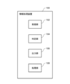
- FIG. 15 is a functional block diagram showing the logical configuration of an information processing device 100 according to an embodiment.
- the information processing device 100 includes a receiving unit 102, a determining unit 104, and an output unit 106.
- the receiving unit 102 receives hardening state information capable of identifying the hardening state of the mold material from a detection means (sensor 40) that is positioned in advance before the mold material is filled so as to face the mold material when the mold material is filled into a master model for making a mold.
- the determination unit 104 repeatedly determines whether or not it is time to demold the mold, using the received cured state information. When it is determined that it is time to remove the mold, the output unit 106 outputs information indicating that it is time to remove the mold.
- the detection means is a strength sensor that contacts the surface of molding sand 32 made of mold material 30, measures the strength of molding sand 32 during hardening, and outputs a value indicating the hardness of molding sand 32.
- the detection means is a sensor that measures the electrical conductivity, dielectric constant, or temperature of molding sand 32 made of mold material 30.
- connection between each sensor and the information processing device 100 may be an analog connection or a digital connection.
- the sensor may also have a wireless communication function.
- the wireless communication function may be, for example, a wireless LAN (Local Area Network) or Bluetooth (registered trademark) for short-range wireless communication. If the sensor has a wireless communication function, the sensor may transmit a measurement value to the information processing device 100, or may transmit a measurement value to the communication device 202. Alternatively, the sensor may transmit a measurement value to the controller 200. The controller 200 may then transmit the measurement value to the information processing device 100 via the communication device 202.
- the information processing device 100 When the sensor transmits a measurement value directly to the information processing device 100, the information processing device 100 stores identification information such as the IP address of the sensor in the sensor information 130 and uses it when receiving curing state information from the sensor. Alternatively, when transmitting measurement values from the sensor to the information processing device 100 via the communication device 202, the information processing device 100 associates identification information, such as the IP address of the sensor, with identification information, such as the IP address of the communication device 202, and stores the association in the storage device 120, and uses the association when receiving curing state information from the sensor via the communication device 202.
- identification information such as the IP address of the sensor
- identification information such as the IP address of the communication device 202
- the measurement values are output from the sensor successively, periodically, or whenever requested.
- Each sensor may also have a memory that holds the measurement values for a predetermined period of time.
- FIG. 16 is a diagram showing an example of the data structure of the sensor information 130.
- the sensor information 130 includes, for each sensor 40, at least identification information (shown as "sensor ID” in the figure) capable of identifying the sensor 40, information indicating the type of the sensor 40 (strength sensor (pressure sensor, position sensor, load cell, etc.), electrical conductivity sensor, dielectric constant sensor, temperature sensor, etc.), and information capable of identifying the measurement data output from the sensor 40.
- Information that can identify the measurement data is, for example, in the case of a hardness sensor, information that can identify the hardness test method (for Vickers hardness, the hardness symbol "HV”, for Brinell hardness, the hardness symbol "HBW”, etc.), in the case of an electrical conductivity sensor or dielectric constant sensor, information indicating the moisture content (%: liquid/solid) of the molding sand 32, and in the case of a temperature sensor, information indicating the temperature (°C) of the molding sand 32, etc.
- a hardness sensor information that can identify the hardness test method (for Vickers hardness, the hardness symbol "HV”, for Brinell hardness, the hardness symbol "HBW”, etc.), in the case of an electrical conductivity sensor or dielectric constant sensor, information indicating the moisture content (%: liquid/solid) of the molding sand 32, and in the case of a temperature sensor, information indicating the temperature (°C) of the molding sand 32, etc.
- FIG. 17 is a diagram showing an example of the data structure of the mold information 140.
- the mold information 140 includes at least, for each mold 10, identification information capable of identifying the mold 10 (shown as "mold ID” in the figure), information on the casting product to be manufactured using the mold 10 (e.g., product type, product name, etc.), and information on the mold material 30 of the mold 10 (e.g., type of molding sand, type, mixing ratio, and amount of hardener, type and amount of binder, sand temperature, air temperature, and humidity at the time of molding, etc.).
- identification information capable of identifying the mold 10 shown as "mold ID” in the figure
- information on the casting product to be manufactured using the mold 10 e.g., product type, product name, etc.
- information on the mold material 30 of the mold 10 e.g., type of molding sand, type, mixing ratio, and amount of hardener, type and amount of binder, sand temperature, air temperature, and humidity at the time of molding,
- the identification information of the mold 10 is, for example, attached in advance to the outside of the master 20 in the form of an IC tag, barcode, or two-dimensional code on which the identification information is recorded. However, a label on which the identification information is written may also be attached. Then, when the mold material 30 is filled in the molding process S1, the identification information is read from the IC tag, barcode, or the like using a reading device.
- the information processing device 100 receives the identification information of the mold 10, it may refer to the mold information 140, read the mold material 30, molding conditions, and the like, and send them to the controller 200.
- the worker may input the identification information written on the label by operating the UI from the input screen.
- the input screen may be displayed on the display of the terminal device 280 or mobile terminal 282 operated by the worker from the settings menu of the application or website described above.
- FIG. 18 is a diagram showing an example of the data structure of the sensor installation information 150.
- the sensor installation information 150 includes at least, for each mold 10, identification information (shown as "mold ID” in the figure) that can identify the mold 10, identification information (shown as “sensor ID” in the figure) that can identify the sensor 40 installed on the mold 10, information indicating the installation position for each sensor 40, and information regarding a reference value for determining the timing of demolding from the hardening state information of the sensor 40.
- the reference value for determining the timing of demolding can be set and changed as appropriate by the user.
- an operation screen including a UI for accepting user operations can be displayed on the display, and the setting or change of the reference value can be accepted through user operation.
- the reference value of the sensor installation information 150 is set or updated and stored in the storage device 120.
- the method of arranging the sensor 40 is exemplified below, but is not limited to this.
- the placement of the sensor 40 is determined in advance and stored in the sensor installation information 150, and the sensor 40 is placed based on the installation position information of the sensor 40 with reference to the sensor installation information 150.
- the identification information of the mold 10 is read from an IC tag, barcode, or the like using a reading device.
- the information processing device 100 receives the identification information of the mold 10, it refers to the sensor installation information 150 and reads out the identification information and installation position information of the sensor 40.
- the information processing device 100 may display the read identification information and installation position information of the sensor 40 on the display of the terminal device 280.
- the worker can place the sensor 40 while checking the display. For example, if the placement position is indicated by coordinates, it is preferable to mark the coordinate scale on the bottom plate 22 or the molding flask 26 in advance.
- the sensor 40 can be placed according to the scale.
- the position of the sensor 40 placed on the bottom plate 22 other than the product section 24 may be input by the worker using the terminal device 280 or mobile terminal 282 to operate the UI from the input screen.
- the identification information of the sensor 40 and the placement position of the sensor 40 are input for each sensor 40.
- the identification information of the sensor 40 may be, for example, an IC tag or barcode attached to the sensor 40, as with the mold 10, or a label may be attached.
- the IC tag or barcode attached to the prototype 20 is read by a reading device to obtain the identification information of the mold 10.
- the worker may input the identification information written on the label by operating the input screen described above.
- the information processing device 100 may record the input position information in the sensor installation information 150 in association with the obtained identification information of the mold 10.
- the reference value used in the determination process of the demolding timing may be, for example, a reference value that is predetermined for each type of sensor 40.
- the reference value may be stored in the sensor information 130.
- the determination unit 104 of the information processing device 100 can refer to the sensor information 130, obtain the reference value linked to the identification information of the installed sensor 40, and use it in the determination process.
- the information indicating the installation position of the sensor 40 are possible, and are exemplified below, but are not limited to these.
- the information indicating the installation position may be different for each sensor 40.
- (a1) In the case of sensor 40 disposed on bottom plate 22, the distance from the outer edge of product portion 24 to the center of sensor tip 42 of sensor 40 is indicated as L1 (FIG. 3, etc.).
- (a2) In the case of the sensor 40 disposed in the molding flask 26, the distance in the height direction from the upper surface 22a of the bottom plate 22 to the center of the sensor tip 42 of the sensor 40 is indicated as L2 (FIG. 4, etc.).
- the sensor 40 In the case of a sensor 40 disposed on the bottom plate 22, the sensor 40 is indicated by a two-dimensional coordinate position on the upper surface 22a of the bottom plate 22. (a4) In the case of a sensor 40 disposed in the flask 26, the position is indicated by a two-dimensional coordinate position on the inner surface 26a of the flask 26 (FIG. 6). (a5) The location where the sensor 40 is placed is indicated by being at least one of the bottom plate 22, the molding flask 26, and the upper surface 32a of the molding sand 32.
- the above (a5) is an example of a case where the exact location is not specified, or where the exact installation location is predetermined for each location.
- the information may indicate whether the installation location is the bottom plate 22, the flask 26, or both the bottom plate 22 and the flask 26.
- the information may indicate on which side (for example, the front, left side, right side, rear side, etc. when viewing the flask 26 from a certain direction) the installation location is.
- Information regarding the reference value for determining the timing of demolding from the curing state information of the sensor 40 may be set according to the type and installation position of the sensor 40, the conditions of the mold material 30, the molding conditions, etc., or a fixed standard may be used. As will be explained in the embodiment described later, this reference value may be optimized using history information.
- the receiving unit 102 receives from the sensor 40 the hardness value of the molding sand 32, and the measured values of the electrical conductivity, dielectric constant, or temperature of the molding sand 32 as hardening state information capable of identifying the hardening state of the mold material.
- the receiving unit 102 receives the measured values output from the sensor 40 via the communication device 202.
- the receiving unit 102 periodically and repeatedly receives the measured values from the sensor 40.
- the measurement values from the sensor 40 may be received at any time.
- the sensor 40 may be inserted into the measurement position and the measurement may be received at a predetermined timing while the measurement is being performed.
- the location must be moved for the next measurement. For this reason, it is preferable, for example, to previously place multiple sensors in different locations (or form multiple holes 50) and use the sensors one by one (or move the holes 50) at time intervals to perform measurements.
- the hardening speed, pot life, and demolding time of the mold 10, such as a self-hardening mold, can be estimated based on molding conditions such as air and sand temperatures, type of sand, type, mixing ratio and supply amount of hardener, and type and supply amount of binder.
- the molding conditions or demolding time (set value) can be acquired from the controller 200.
- the receiving unit 102 can estimate or acquire the demolding time from the time when filling of the mold material 30 begins, and start receiving the measurement value of the sensor 40 a predetermined time before the demolding time to determine the timing of demolding.
- the receiving unit 102 receives the curing state information from the sensor 40, which is placed in a part of the master different from the product portion 24.
- the sensor 40 is placed in a part of the master different from the product portion 24. In this way, since the sensor 40 is placed in a part of the master different from the product portion 24, the sensor 40 does not affect the product portion of the mold 10, and therefore does not degrade the quality of the mold 10.
- FIG. 19 is a diagram showing an example of the data structure of the curing state information 160.
- the cured state information 160 includes at least, for each sensor 40, identification information (indicated as "sensor ID” in the drawing) capable of identifying the sensor 40, information indicating the date and time of measurement by the sensor 40, and measurement data received from the sensor 40.
- the mold information 140 may include information indicating the cured state calculated from the measurement data.
- the curing state information 160 stores a value indicating intensity as measurement data.
- the measurement data stored includes the physical property values and measurement values. In the case of an ultrasonic sensor, the response time and intensity of the reflected wave are stored.
- the hardening state information is information that indicates the result of the judgment made by the judgment unit 104 described later.
- the hardening state information is, for example, information that indicates whether or not the criteria for judging the timing for demolding have been met. As an example, it can be indicated by a flag, and if the criteria for the timing for demolding are met, "1" is set, and if the criteria are not met, "0" is set.
- the receiving unit 102 stores the curing state information received from the sensor 40 as curing state information 160 in the storage device 120.
- the determining unit 104 determines whether the value indicating the hardness is equal to or greater than a reference value. When the value indicating the hardness is equal to or greater than the reference value, the determining unit 104 determines that it is time to demold the mold.
- the determining unit 104 determines whether the moisture content is less than a reference value. When the moisture content falls below the reference value, the determining unit 104 determines that it is time to demold the mold.
- the determining unit 104 calculates the temperature change and determines whether the temperature change satisfies a criterion.
- the temperature change criterion is, for example, that the temperature change is constant after a predetermined time has elapsed (the predetermined time is set based on the demolding time estimated from the type and distribution ratio of the hardener, the air temperature, and the sand temperature), or that it indicates a decreasing state, or that it is the time at which a peak value is obtained.
- the determining unit 104 determines that the demolding timing is when the temperature change satisfies the criterion, or the time calculated from the time when the criterion is satisfied.
- a plurality of sensors 40 may be disposed inside the bottom plate 22 and the molding flask 26 .
- the determination unit 104 determines the demolding timing using the curing state information generated by each of the multiple sensors 40. Methods for determination using the information from the multiple sensors 40 are exemplified below, but are not limited to these. Since the demolding timing can be determined using multiple sensors 40, the determination accuracy of the demolding timing can be maintained regardless of the size or shape of the mold 10, for example.
- the determining unit 104 determines that it is time to remove the mold when the hardening state information from a predetermined number of the sensors 40 satisfies a criterion.
- the predetermined number is, for example, the total number of the sensors 40 that are arranged.
- the timing for demolding is determined using information from a predetermined number (for example, all) of the curing state information from the multiple sensors 40, so that the timing for demolding can be specified more precisely.
- the determination unit 104 determines that it is time to remove the mold when the curing state information from a predetermined number of sensors 40 satisfies a first criterion and the variation in the curing state information from the multiple sensors 40 satisfies a second criterion.
- the first criterion is that the curing state information indicates a strength appropriate for the die, and the predetermined number is, for example, the total number or a predetermined percentage (e.g., 90%) of the total number.
- the second criterion is that the variation in the curing state information of the multiple sensors 40 (e.g., the total number) is less than a threshold value.
- the output unit 106 When the determination unit 104 determines that it is time to remove the mold, the output unit 106 outputs information indicating that it is time to remove the mold.
- the output unit 106 may display the information in a manner that can be recognized within the foundry, such as by using a Patlite (registered trademark). Alternatively, the output unit 106 may output the information to a display. Specifically, the output unit 106 may cause the information to be output to a display of the terminal device 280 or the mobile terminal 282 via the communication network 3. Since the information indicating that it is time to remove the mold is output to the display, the worker or manager can confirm that it is time to remove the mold for each mold 10 based on the output information. This makes it possible to perform the mold removal operation at the appropriate timing.
- FIG. 20 is a diagram showing an example of the output screen 300.
- the output screen 300 is a screen for managing the demolding process.
- the output screen 300 includes a display field 310 for displaying the mold ID of each mold 10 being made, and a display field 320 for displaying information indicating whether or not it is time to demold based on the hardening state.
- information on a plurality of molds 10 is included on one screen, but it would also be possible to have one screen (for example, a pop-up screen or a notification screen) for each mold 10.
- Display field 320 displays a notation such as "Can be punched” to indicate that it is time to punch, or “Cannot be punched” to indicate that it is not time to punch.
- a notation such as "Can be punched” to indicate that it is time to punch, or “Cannot be punched” to indicate that it is not time to punch.
- these notations are merely examples and are not limiting.
- the display field 320 may highlight 322 a notation indicating that it is time to remove the mold.
- highlight 322 include, but are not limited to, highlight display, reverse display, blinking display, animation display, bolding of text, enlarging text size, changing the color of text or background (e.g., from black to red), etc.
- the information indicating whether or not it is time to cut the mold may be indicated by text, symbols (such as a "check” or “OK” if cutting is possible, and a "- (bar)” or “NG” if cutting is not possible), pictograms, icons, or colors (such as green if cutting is possible and red if cutting is not possible).
- the output unit 106 may also display that it is soon time to punch the mold. For example, two stages of criteria for determining the punching timing are set, and the judgment unit 104 performs judgment processing. The judgment unit 104 may determine that it is soon time to punch the mold when the first stage criteria are met, and determine that it is soon time to punch the mold when the second stage criteria are met.
- the output screen 300 may further include a confirmation button 330.
- a confirmation button 330 For example, when the highlight 322 on the output screen 300, which indicates that it is time to remove the mold, is blinking, the output unit 106 may perform a process to stop the blinking display when the confirmation button 330 is pressed.
- the confirmation button 330 may be provided for each mold 10.
- the output unit 106 may perform a process to close the output screen 300 when the confirmation button 330 is pressed.
- the information output from the output unit 106 may be a demolding instruction signal.
- the information output from the output unit 106 may be a demolding permission signal.
- the demolding instruction signal is transmitted to the demolding device 240 via the communication device 202.
- the demolding device 240 Upon receiving the information, the demolding device 240 performs a demolding operation and removes the mold 10.
- the demolding operation may include, for example, an operation of transporting the corresponding mold 10 to a position where it is demolded.
- the decision as to whether or not it is time to remove the mold can also be made by the worker.
- the output unit 106 outputs information for the worker to decide whether or not it is time to remove the mold.
- the output unit 106 outputs the curing state information and the reference value used to determine the timing of die-punching to the display.
- the worker presses a die-punch operation switch or the like provided on the operation panel of the die-punch device 240.
- the die-punch device 240 performs the die-punch operation.
- the worker may press the die-punch operation switch or the like to cause the die-punch device 240 to perform the die-punch operation. In this way, when the die-punch timing arrives, the die-punch operation can be performed after a person has confirmed it.
- FIG. 21 is a flowchart showing an example of the operation of the information processing device 100 according to the embodiment. This flow is started at a predetermined timing, which includes, but is not limited to, the following examples: (b1) When the control panel 222 receives an operation from the kneader 220 to instruct the start of filling the mold material 30 into the master 20, the controller 200 receives a signal indicating the start of filling from the control panel 222. Then, when the information processing device 100 receives information indicating the start of filling from the controller 200, it starts this flow. (b2) After receiving the information indicating the start of filling in (b1), this flow is started after a first predetermined time has elapsed.
- first predetermined time pot life+second predetermined time.
- the receiving unit 102 receives hardening state information capable of identifying the hardening state of the mold material 30 from a detection means (sensor 40) that is positioned before the mold material is filled so as to face the mold material 30 when the mold material 30 is filled into at least one of the base plate 22 and the flask 26 used to make the mold 10 (step S101).
- the determination unit 104 uses the received hardening state information to determine whether it is time to demold the mold 10 (step S103). If it is determined that it is not time to demold (NO in step S103), the process returns to step S101.
- the receiving unit 102 receives the hardening state information from the sensor 40 (step S101), and the determination unit 104 repeats the determination process (step S103) until it is time to demold. As described above, the receiving unit 102 may execute the reception process at a predetermined time interval.
- the output unit 106 outputs information indicating that it is time to remove the mold (step S105).
- FIG. 22 is a flowchart showing the details of the output process of step S105. At least one of steps S111 and S113 is executed.
- the output unit 106 outputs a die-removal instruction signal (step S111).
- the output destination of the die-removal instruction signal is, for example, the die-removal device 240 or the controller 200 .
- the die-pulling device 240 starts the die-pulling operation.
- the die-punching device 240 transitions to a state in which the die-punching operation is permitted. After that, the following process (c3) or (c4) is executed. Furthermore, the die-punching operation may be started in response to the operator pressing an operation switch for instructing the die-punching operation, which will be described later.
- An indicator provided on the operation panel (not shown) of the die-cutting device 240 or the controller 200 is turned on or blinks to notify the operator that the die-cutting time has arrived.
- a buzzer sound, voice, music, etc. is output from a speaker on the operation panel to notify the operator that it is time to start die-cutting.
- the output unit 106 displays information indicating that it is time to remove the mold on the display (step S113).
- the destination of the information is at least one of the terminal device 280 and the mobile terminal 282.
- the output unit 106 displays the output screen 300 of Fig. 20 on the display of the terminal device 280 or the mobile terminal 282.
- the information displayed on the display of the terminal device 280 or the mobile terminal 282 is not limited to the output screen 300 of Fig. 20.
- the output unit 106 may output the information indicating that it is time to remove the mold on a pop-up window or a notification screen.
- the worker may check the displayed, audio, or notified information, and press an operation switch that instructs the die-cutting operation provided on the operation panel of the die-cutting device 240 to cause the die-cutting device 240 to perform the die-cutting operation. Alternatively, the worker may perform the die-cutting operation.
- the information processing device 100 includes a receiving unit 102, a determining unit 104, and an output unit 106.
- the receiving unit 102 receives hardening state information capable of identifying the hardening state of the mold material from a detection means (sensor 40) that is arranged beforehand before filling the mold material so as to face the mold material when the mold material is filled into a master model for producing a mold.
- the determining unit 104 repeatedly determines whether or not it is time to demold the mold using the received hardening state information. When it is determined that it is time to demold, the output unit 106 outputs information indicating that the demolding time has arrived.
- the optimal timing for demolding based on the strength of the product surface side inside the mold, which is difficult to judge from the outside of the mold, regardless of the shape or size of the mold 10.
- the reason for this is that a detection means is placed in advance on at least one of the bottom plate 22 and the molding flask 26 before the mold material 30 is filled, and hardened state information is received from the detection means by the receiving unit 102 after the mold material 30 is filled, and the timing for demolding can be determined by the determining unit 104 using the hardened state information located on the product side of the molding sand 32, rather than on the top surface of the molding sand 32 or a position away from the product side by a filling distance.
- the output unit 106 can output information indicating that it is time to remove the mold, so that the mold removal device 240 can perform the mold removal operation based on that information.
- the information can be output to the terminal device 280 or mobile terminal 282 used by the worker, so that the worker can check the timing to remove the mold 10 and perform the mold removal operation.
- Third Embodiment Fig. 23 is a functional block diagram showing a logical configuration of an information processing device 100 according to an embodiment.
- the information processing device 100 in Fig. 23 has the same configuration as the information processing device 100 in Fig. 15, and further includes a processing unit 108.
- the information processing device 100 of this embodiment is similar to any of the above-mentioned embodiments, except that it has a configuration for performing a process for optimizing the molding conditions and the arrangement position of the detection means based on the demolding time.
- the configuration of this embodiment can be combined with the configuration of any of the other embodiments to the extent that no contradiction occurs.
- the processing unit 108 measures the demolding time for each mold 10, compares it with the set demolding time, and if there is a difference between the actual measured value and the set value, performs a process to accept changes to the molding conditions.
- the processing unit 108 acquires the molding start time, and when it acquires a demolding instruction signal indicating that it is time to demold, it acquires the time at which the signal was received.
- the processing unit 108 then calculates the molding start time and the demolding time (actual measured value) taken from the start of filling the mold material 30 to demolding from the reception time.
- the demolding time of the mold 10 can be calculated as a reference value from the pot life and hardening time estimated from the molding conditions of the mold 10.
- the processing unit 108 compares the actual demolding time with the reference value and determines whether the difference is equal to or greater than a threshold value.
- the output unit 106 outputs information regarding adjustment of the molding conditions of the mold 10.
- the molding conditions for the mold 10 include the type of sand, the type, mixing ratio and supply amount of the hardener, and the type and supply amount of the binder.
- the information regarding adjustment includes, for example, information indicating that the molding conditions need to be changed.
- the information may include, along with the identification information for the mold 10, a message such as "The actual measured demolding time for the mold 10 (mold ID) deviates from the standard value. Please adjust the molding conditions.”
- the output unit 106 can display an operation screen including a UI that accepts user operations on the display and accepts changes to the modeling conditions through user operations.
- the processing unit 108 updates the modeling conditions in the mold information 140 and stores them in the storage device 120.
- the processing unit 108 associates the above-mentioned molding start time, the calculated actual value of the demolding time, and information about the mold 10 for each mold 10, and stores them in the storage device 120 as demolding history information 170.
- FIG. 24 is a diagram showing an example of the data structure of the die cutting history information 170.
- the demolding history information 170 includes, for each mold 10, the identification information of the mold 10, the start time of molding, the calculated actual value of the demolding time, and information related to the mold 10, all of which are associated with each other.
- the information about the mold 10 is, for example, information indicating the state of the completed mold 10.
- the information about the mold 10 includes, for example, information indicating the presence or absence of deformation, collapse, or chipping of the mold 10, the hardness of the mold 10, and the quality of the mold 10.
- the information about the mold 10 may include information indicating the accuracy of the cast product manufactured using the mold 10 (such as the deviation from the design dimensions and shape).
- the mold removal history information 170 may record the number of times the mold 10 has been used to manufacture cast products.
- the processing unit 108 may perform statistical processing of the mold removal history information 170 and adjust the molding conditions that can produce a high-quality mold 10 and the position of the detection means based on the information about the mold 10.
- the information processing device 100 may be configured to provide feedback on the shape (size, height, thickness) of the mold 10, the position where the detection means is located, and whether the hardening state information of the detection means located at which position can be used to determine the appropriate timing for demolding. This makes it possible to optimize the reference value used to determine the timing for demolding.
- FIG. 25 is a flowchart showing an example of the operation of the information processing device 100 according to the embodiment.
- the processing unit 108 acquires the mold-making start time and records it in the storage device 120 (step S201). Furthermore, the processing unit 108 acquires the identification information of the mold 10 and acquires the molding conditions of the mold 10 from the mold information 140 (step S203). Then, the information processing device 100 executes the process flow of Fig. 21 (mold-removal timing monitoring process) (step S205).
- the processing unit 108 acquires the signal (step S207). The processing unit 108 then calculates the actual demolding time based on the time the signal was received and the start time of molding the mold 10 (step S209).
- the processing unit 108 compares the actual demolding time with the reference value and determines whether the difference is equal to or greater than a threshold value (step S211). If the difference is equal to or greater than the threshold value (YES in step S211), the output unit 106 outputs information regarding adjustment of the molding conditions of the mold 10 if the difference between the time measured from the start of molding to the timing of demolding (actual demolding time) and the reference value is equal to or greater than the threshold value (step S213). The processing unit 108 then accepts the change, updates the molding conditions in the mold information 140, and stores them in the storage device 120 (step S215). On the other hand, if the difference is not equal to or greater than the threshold value in the determination in step S211 (NO in step S211), steps S213 to S215 are bypassed and this process ends.
- this embodiment not only provides the same effects as the above embodiment, but also allows for processing to optimize the molding conditions and the position of the detection means based on the demolding time.
- the reason for this is that when the difference between the time measured from the start of molding to the timing of demolding (actual demolding time) and a reference value is equal to or greater than a threshold value, the output unit 106 outputs information regarding adjustment of the molding conditions for the mold 10.
- FIG. 26 is a diagram showing an example of the arrangement of a detection means in a mold preparation method according to another embodiment.
- the example of FIG. 26(a) is a cross-sectional view including molding sand 32 in which the molding material 30 is filled inside the space formed by combining core masters 70a and 70b.
- the molding sand 32 which becomes the core includes a product portion 34 which becomes the product part, and a baseboard portion 36 which serves to fix the product portion 34 on both sides.
- the sensor 40 (detection means) is built into at least one of the master patterns 70a and 70b.
- the sensor 40 has, for example, a sensor tip (not shown) that contacts the surface of the molding sand 32 made of the mold material 30, measures the strength of the molding sand 32 during hardening, and outputs a value indicating the hardness of the molding sand 32.
- the sensor 40 is built into the master patterns 70a and 70b for the core so that the sensor tip faces the surface of the molding sand 32.
- the sensor 40 is then installed in a portion of the master molds 70a and 70b that is different from the product portion 34 that corresponds to the casting product produced in the mold 10 (in the example of FIG. 26(a), the baseboard portion 36).
- the master 70b of Figure 26(a) further has push-out pins 76 provided in the product section 34 and baseboard section 36.
- the sensor 40 is provided at the tip of the push-out pin 76 provided in the baseboard section 36 on the molding sand 32 side.
- the sensor 40 is inserted into the hole 78 into which the push-out pin 76 is inserted, and is positioned so that the sensor tip of the sensor 40 abuts against the surface of the baseboard section 36 of the molding sand 32.
- the sensor 40 is built into the master 70a or 70b, but as in the above embodiment, the sensor may be installed on the surface of the portion of the master 70a or 70b that corresponds to the baseboard portion 36.
- the mold 10 was made using the mold material 30, which is a mixture of refractory particles, a binder, and a hardener.
- a method for making a mold can be provided in which the mold 10 is made using a green sand method in which sand is compressed under pressure, or a gas hardening method in which gas is used as a hardener.
- a method for optimizing the installation position of the sensor 40 according to the molding conditions of a mold using the information processing device 100 of the above embodiment may be provided.
- a method may be provided in which a sensor 40 is installed at an installation position optimized using this method and a mold is produced at the timing for demolding determined.
- a detection means for generating hardening state information capable of identifying the hardening state of a mold material is disposed in a master for producing a mold before the mold material is filled, so that the detection means faces the mold material when the mold material is filled; Then, the mold material is filled into the interior of the master.
- the mold manufacturing method further comprises obtaining the curing state information while the mold material is curing, and stripping the mold. 2.
- the method for producing a template according to 1. The method for producing a mold, wherein the detection means is disposed in an area of the master other than the product portion. 3. In the method for producing a template according to 1.
- the method of making a mold further comprising disposing at least a portion of the detection means embedded in the master. 4.
- the method of making a mold further comprising disposing the detection means on an inner surface of the master. 5.
- a mold manufacturing method comprising forming a hole in the master mold capable of accommodating the detection means and through which the detection means can move, and exposing at least a portion of the detection means from the hole at least at the timing when the curing state information is to be generated. 6.
- the method of making a mold further comprising: determining an internal hardness of the mold using the cured state information. 7.
- the method for making a mold wherein the mold is a self-hardening mold.
- a method for producing a mold wherein the binder contained in the mold material is any one of a furan resin, a phenol resin, an alkaline phenol resin, and water glass.
- the master comprises a bottom plate, a product portion, and a molding flask.
- a receiving unit that receives hardening state information that can specify the hardening state of the mold material from a detection means that is arranged before filling the mold material so as to face the mold material when the mold material is filled into a master model for making a mold, and A determination unit that repeatedly determines whether or not it is time to demold the mold using the received curing state information; and an output unit that outputs, when it is determined that the die-removal timing has arrived, information indicating that the die-removal timing has arrived. 11. In the information processing device according to 10., The output unit outputs the information to a display. 12. In the information processing device according to 10. or 11., The receiving unit receives the curing state information from the detection means arranged in an area of the master other than the product portion. 13.
- a plurality of the detection means are disposed inside the master, The determination unit determines the timing of demolding by using the hardening state information generated by each of the plurality of detection means. 14. In the information processing device according to 13., The determination unit determines that it is time to remove the mold when the hardening state information of a predetermined number of the detection means satisfies a criterion. 15.
- the information processing device In the information processing device according to 14., The information processing device, wherein the judgment unit judges that it is time to remove the mold when the curing state information of a predetermined number of the detection means satisfies a first criterion and the variation in the curing state information of the multiple detection means satisfies a second criterion. 16. In the information processing device according to any one of 10. to 15., The output unit outputs information regarding adjustment of molding conditions of the mold when a difference between a time measured from a molding start time to the demolding timing and a reference value is equal to or greater than a threshold value.
- One or more computers receiving, from a detection means arranged in advance before filling the mold material, information on a hardening state capable of identifying a hardening state of the mold material, so as to face the mold material when the mold material is filled into a master for producing a mold; Using the received curing state information, it is repeatedly determined whether or not it is time to demold the mold; When it is determined that the timing for die removal has arrived, information indicating that the timing for die removal has arrived is output. 18.
- An information processing method comprising: outputting the information to a display. 19.
- the information processing method includes receiving the curing state information from the detection means arranged in an area of the master other than the product portion. 20. In the information processing method according to any one of 18. to 19., A plurality of the detection means are disposed inside the master, the one or more computers, The timing of demolding is determined using the hardening state information generated by each of the plurality of detection means. 21. In the information processing method according to 20., the one or more computers, The information processing method determines that it is time to remove the mold when the hardening state information from a predetermined number of the detection means satisfies a criterion. 22.
- An information processing method comprising: determining that it is time to remove the mold when the curing state information of a predetermined number of the detection means satisfies a first criterion and the variation in the curing state information of the multiple detection means satisfies a second criterion. 23.
- An information processing method comprising: when a difference between a time measured from a molding start time to the demolding timing and a reference value is equal to or greater than a threshold value, outputting information regarding adjustment of molding conditions for the mold.
- a receiving process for receiving hardening state information capable of identifying a hardening state of the mold material from a detection means that is arranged before filling the mold material so as to face the mold material when the mold material is filled into a master model for producing a mold; a determination process for repeatedly determining whether or not it is time to demold the mold using the received curing state information; and an output process for outputting information indicating that the timing for die-removal has arrived when it is determined that the timing for die-removal has arrived.
- a computer program product that outputs the information to a display in the output process.
- the computer program according to claim 24 or 25 a computer program for receiving, in the receiving process, the curing state information from the detection means arranged in an area of the master other than the product portion; 27.
- the computer program according to any one of 24 to 26, A plurality of the detection means are disposed inside the master,
- 28. The computer program according to claim 27, a computer program for determining, in the determination process, that it is time to remove the mold when the hardening state information of a predetermined number of the detection means satisfies a criterion. 29.
- the computer program according to claim 28 A computer program that determines, in the judgment process, that it is time to remove the mold when the curing state information of a predetermined number of the detection means satisfies a first criterion and the variation in the curing state information of the multiple detection means satisfies a second criterion.
- the computer program according to any one of claims 24 to 29, A computer program that outputs information regarding adjustment of molding conditions of the mold when the difference between the time measured from the start of molding to the timing of demolding and a reference value is equal to or greater than a threshold value in the output process.
- a receiving process for receiving hardening state information capable of identifying a hardening state of the mold material from a detection means that is arranged before filling the mold material so as to face the mold material when the mold material is filled into a master model for producing a mold; a determination process for repeatedly determining whether or not it is time to demold the mold using the received curing state information; and an output process for outputting information indicating that the timing for punching has arrived when it is determined that the timing for punching has arrived.
- the recording medium according to 31. A computer-readable recording medium storing a computer program for outputting the information to a display in the output process. 33.
- the recording medium according to 31 or 32 A computer-readable recording medium storing a computer program for receiving, in the receiving process, the curing state information from the detection means arranged in an area of the master other than the product portion. 34.
- the recording medium according to any one of 31 to 33, A plurality of the detection means are disposed inside the master, A computer-readable recording medium storing a computer program for determining the timing of demolding by using the hardening state information generated by each of the plurality of detection means in the determination process.
- 35 The recording medium according to 34., A computer-readable recording medium storing a computer program, which determines that it is time to remove the mold when the hardening state information of a predetermined number of the detection means satisfies a criterion in the determination process.
- the recording medium according to 35. A computer-readable recording medium storing a computer program, which determines in the judgment process that it is time to demold if the curing state information of a predetermined number of the detection means satisfies a first criterion and the variation in the curing state information of the multiple detection means satisfies a second criterion.
- 37. The recording medium according to any one of 31 to 36, A computer-readable recording medium storing a computer program, which outputs information regarding adjustment of the molding conditions of the mold when the difference between the time measured from the start of molding to the demolding timing and a reference value is equal to or greater than a threshold value in the output process.
- Information processing system 3 Communication network 10 Mold 10a Upper mold 10b Lower mold 20 Master mold 22 Bottom plate 24 Product section 26 Molding flask 30 Molding material 32 Molding sand 40, 40a, 40b, 40c Sensor 42 Sensor tip 44 Sensor 50 Hole 60 Product area 62 Non-product area 100 Information processing device 102 Receiving unit 104 Determination unit 106 Output unit 108 Processing unit 120 Storage device 130 Sensor information 140 Mold information 150 Sensor installation information 160 Hardening state information 170 Die removal history information 200 Controller 202 Communication device 210 Hopper 212 Sand temperature sensor 220 Kneader 222 Control panel 230a Hardener A tank 230b Hardener B tank 232a Hardener A supply unit 232b Hardener B supply unit 235 Piping 236 Binder tank 238 Binder supply section 240 Die-removal device 250 Molten metal 260 Product 270 Reclaimed sand 280 Terminal device 282 Portable terminal 300 Output screen 1000 Computer 1010 Bus 1020 Processor 1030 Memory 1040 Storage device 1050 Input/output interface 1060 Network interface
Landscapes
- Engineering & Computer Science (AREA)
- Mechanical Engineering (AREA)
- Chemical & Material Sciences (AREA)
- Materials Engineering (AREA)
- Casting Devices For Molds (AREA)
- Moulds For Moulding Plastics Or The Like (AREA)
Abstract
鋳型作製方法は、鋳型を作製するための原型に、鋳型材料の硬化状態を特定可能な硬化状態情報を生成する検出手段を、鋳型材料が充填された場合に当該鋳型材料に面するように、前記鋳型材料を充填する前までに予め配置し(ステップS11)、その後、原型の内部に鋳型材料を充填し(ステップS13)、鋳型材料の硬化中に、硬化状態情報を用いて、鋳型を抜型すべき抜型タイミングを判断し(ステップS16)、当該抜型タイミングで鋳型の抜型を行う(ステップS17)、ことを含む。
Description
本発明は、鋳造用の鋳型作製方法、鋳型作製システム、情報処理装置、情報処理システム、情報処理方法、コンピュータプログラム、および記録媒体に関する。
鋳造用の鋳型として、砂型は広く用いられており、一般には、原型に鋳型材料を充填し、鋳型を硬化させた後には、抜型工程が必ず含まれる。抜型工程では、鋳型を慎重に原型から取り出すことが必要であるが、抜型時の鋳型の強度が十分でないと、鋳型の破損や変形、寸法変化が生じ適正な鋳型が得られない。一方で、鋳型の生産性の面ではより早く抜型することが求められるため、抜型時、強度が不十分なまま抜型してしまうことがある。このような事態を防ぐため、鋳型の製造に使用した混錬砂を用いて別取りでテストピースを造型し強度を測定することが行われている。しかしながら、実際の製品鋳型とは形状が異なるため、参考にはなるものの必ずしも実鋳型の強度とは一致していない。
そこで、抜型前の鋳型の強度を測定し、抜型による鋳型の崩れや歪みの発生を抑制する技術の一例が特許文献1に記載されている。特許文献1に記載の鋳型強度計測装置は、製品面及び製品面の反対側の背面を有する鋳型の強度に関する情報を取得する。この鋳型強度計測装置は、切削工具とプローブとを備える。切削工具は、鋳型に背面から製品面に向けて延びる有底の穴を形成する。測定プローブは、穴に挿入可能であり、穴の底部から受けた反力を計測する。
本発明の各側面では、上述した課題を解決するために、それぞれ以下の構成を採用する。
第一の側面は、鋳型作製方法に関する。
第一の側面の鋳型作製方法は、
鋳型を作製するための原型に、鋳型材料の硬化状態を特定可能な硬化状態情報を生成する検出手段を、前記鋳型材料が充填された場合に当該鋳型材料に面するように、前記鋳型材料を充填する前までに予め配置し、
その後、前記原型の内部に前記鋳型材料を充填し、
前記鋳型材料の硬化中に、前記硬化状態情報を得て、
得られた前記硬化状態情報を用いて、前記鋳型を抜型すべき抜型タイミングであると判定した後、前記鋳型の抜型を行う、ことを含む。
第一の側面の鋳型作製方法は、
鋳型を作製するための原型に、鋳型材料の硬化状態を特定可能な硬化状態情報を生成する検出手段を、前記鋳型材料が充填された場合に当該鋳型材料に面するように、前記鋳型材料を充填する前までに予め配置し、
その後、前記原型の内部に前記鋳型材料を充填し、
前記鋳型材料の硬化中に、前記硬化状態情報を得て、
得られた前記硬化状態情報を用いて、前記鋳型を抜型すべき抜型タイミングであると判定した後、前記鋳型の抜型を行う、ことを含む。
第二の側面は、情報処理装置に関する。
第二の側面に係る情報処理装置は、
鋳型を作製するための原型に鋳型材料が充填された場合に当該鋳型材料に面するように、前記鋳型材料を充填する前までに予め配置された検出手段から前記鋳型材料の硬化状態を特定可能な硬化状態情報を受信する受信部と、
受信した硬化状態情報を用いて、前記鋳型を抜型すべき抜型タイミングであるか否かを繰り返し判定する判定部と、
前記抜型タイミングであると判定された場合、前記抜型タイミングになったことを示す情報を出力する出力部と、を有する。
第二の側面に係る情報処理装置は、
鋳型を作製するための原型に鋳型材料が充填された場合に当該鋳型材料に面するように、前記鋳型材料を充填する前までに予め配置された検出手段から前記鋳型材料の硬化状態を特定可能な硬化状態情報を受信する受信部と、
受信した硬化状態情報を用いて、前記鋳型を抜型すべき抜型タイミングであるか否かを繰り返し判定する判定部と、
前記抜型タイミングであると判定された場合、前記抜型タイミングになったことを示す情報を出力する出力部と、を有する。
第三の側面は、1以上のコンピュータにより実行される情報処理方法に関する。
第三の側面に係る情報処理方法は、
1以上のコンピュータが、
鋳型を作製するための原型に鋳型材料が充填された場合に当該鋳型材料に面するように、前記鋳型材料を充填する前までに予め配置された検出手段から前記鋳型材料の硬化状態を特定可能な硬化状態情報を受信し、
受信した硬化状態情報を用いて、前記鋳型を抜型すべき抜型タイミングであるか否かを繰り返し判定し、
前記抜型タイミングであると判定された場合、前記抜型タイミングになったことを示す情報を出力する、ことを含む。
第三の側面に係る情報処理方法は、
1以上のコンピュータが、
鋳型を作製するための原型に鋳型材料が充填された場合に当該鋳型材料に面するように、前記鋳型材料を充填する前までに予め配置された検出手段から前記鋳型材料の硬化状態を特定可能な硬化状態情報を受信し、
受信した硬化状態情報を用いて、前記鋳型を抜型すべき抜型タイミングであるか否かを繰り返し判定し、
前記抜型タイミングであると判定された場合、前記抜型タイミングになったことを示す情報を出力する、ことを含む。
第四の側面は、鋳型作製システムに関する。
第四の側面に係る鋳型作製システムは、
鋳型材料の硬化状態を特定可能な硬化状態情報を生成する検出手段を、前記鋳型材料が充填された場合に当該鋳型材料に面するように有する原型と、
情報処理装置と、を備え、
前記情報処理装置は、
前記検出手段から前記鋳型材料の硬化状態を特定可能な硬化状態情報を受信する受信部と、
受信した硬化状態情報を用いて、前記鋳型を抜型すべき抜型タイミングであるか否かを繰り返し判定する判定部と、
前記抜型タイミングであると判定された場合、前記抜型タイミングになったことを示す情報を出力する出力部と、を有し、
前記原型の内部への前記鋳型材料の充填後、
前記情報処理装置が、
前記鋳型材料の硬化中に、前記鋳型材料の硬化状態を特定可能な硬化状態情報を生成する検出手段から、前記硬化状態情報を得て、
得られた前記硬化状態情報を用いて、前記鋳型を抜型すべき抜型タイミングであるか否かを繰り返し判定し、
前記抜型タイミングであると判定された場合、前記抜型タイミングになったことを示す情報を出力する。
第四の側面に係る鋳型作製システムは、
鋳型材料の硬化状態を特定可能な硬化状態情報を生成する検出手段を、前記鋳型材料が充填された場合に当該鋳型材料に面するように有する原型と、
情報処理装置と、を備え、
前記情報処理装置は、
前記検出手段から前記鋳型材料の硬化状態を特定可能な硬化状態情報を受信する受信部と、
受信した硬化状態情報を用いて、前記鋳型を抜型すべき抜型タイミングであるか否かを繰り返し判定する判定部と、
前記抜型タイミングであると判定された場合、前記抜型タイミングになったことを示す情報を出力する出力部と、を有し、
前記原型の内部への前記鋳型材料の充填後、
前記情報処理装置が、
前記鋳型材料の硬化中に、前記鋳型材料の硬化状態を特定可能な硬化状態情報を生成する検出手段から、前記硬化状態情報を得て、
得られた前記硬化状態情報を用いて、前記鋳型を抜型すべき抜型タイミングであるか否かを繰り返し判定し、
前記抜型タイミングであると判定された場合、前記抜型タイミングになったことを示す情報を出力する。
なお、本発明の他の側面としては、上記第三の側面の方法を少なくとも1つのコンピュータに実行させるプログラムであってもよいし、このようなプログラムを記録したコンピュータが読み取り可能な記録媒体であってもよい。この記録媒体は、非一時的な有形の媒体を含む。
このコンピュータプログラムは、コンピュータにより実行されたとき、コンピュータに、情報処理装置上で、その制御方法を実施させるコンピュータプログラムコードを含む。
このコンピュータプログラムは、コンピュータにより実行されたとき、コンピュータに、情報処理装置上で、その制御方法を実施させるコンピュータプログラムコードを含む。
なお、以上の構成要素の任意の組合せ、本発明の表現を方法、装置、システム、記録媒体、コンピュータプログラムなどの間で変換したものもまた、本発明の態様として有効である。
また、本発明の各種の構成要素は、必ずしも個々に独立した存在である必要はなく、複数の構成要素が一個の部材として形成されていること、一つの構成要素が複数の部材で形成されていること、ある構成要素が他の構成要素の一部であること、ある構成要素の一部と他の構成要素の一部とが重複していること、等でもよい。
また、本発明の方法およびコンピュータプログラムには複数の手順を順番に記載してあるが、その記載の順番は複数の手順を実行する順番を限定するものではない。このため、本発明の方法およびコンピュータプログラムを実施するときには、その複数の手順の順番は内容的に支障のない範囲で変更することができる。
さらに、本発明の方法およびコンピュータプログラムの複数の手順は個々に相違するタイミングで実行されることに限定されない。このため、ある手順の実行中に他の手順が発生すること、ある手順の実行タイミングと他の手順の実行タイミングとの一部ないし全部が重複していること、等でもよい。
上記した特許文献1に記載の技術においては、鋳型の製品面と反対側の背面から製品面に向けて測定プローブを挿入して鋳型の強度を測定している。また、特許文献1には、穴の深さが、前記背面と前記製品面との間の距離の1/2以上にすることで、鋳型の性能に影響する鋳型の製品面に「近い部分」の強度を計測することができることが記載されている。このため、特許文献1に記載の技術では、鋳型の製品面側の強度は測定できない。そのため、鋳型の形状においてサイズや厚みや高さが大きい場合に、鋳型の製品面側の硬化が外側に比較して遅れることにより鋳型内部の製品面側の強度が不足し、抜型時に製品面側の鋳型が崩れたり変形したりすることを防ぐことができない。
特に、混錬砂を原型に充填後、時間と共に鋳型の強度が上昇し、抜型可能な鋳型強度となった時点で抜型する自硬性鋳型や、硬化ガスを通気させて硬化反応させるガス硬化鋳型の場合、製品面側の強度を把握し、抜型可能かどうかを判断することは鋳型の破損、変形を防ぐ意味で重要である。
さらに、鋳型内部の水分の揮発や粘結剤中に含まれる水や溶剤の揮発が鋳型の硬化を促進させるタイプの粘結剤を用いた場合、製品面側が最も水分、溶剤の揮発に不利であり、通常最も硬化がしにくい。さらには、様々な鋳型大きさ、形状があった場合、水分、溶剤の揮発は、個々の鋳型形状により変わってくるため、同一の硬化条件で設定しても個々の製品面の硬化状態がそれぞれの鋳型で異なる上、場所によっても異なることがある。
このような中、抜型の際には、最も強度が低い部分が破損、変形することが多いため、製品面側の強度を把握し、適切なタイミングで抜型できるか判断できることは、不良低減や鋳型の生産性向上に寄与できる。
特に、自硬性鋳型の中でも、脱水縮合反応で硬化が進む酸硬化性フラン樹脂や、酸硬化性フェノール樹脂、エステル硬化型のアルカリフェノール樹脂を用いた場合、水が揮発しにくい製品面での硬化が特に遅い一方、外気と接していて水が揮発しやすい背面(製品面と反対側)の硬化が早いため、外部から測定可能な背面の硬さのみで硬化を判断してしまい製品面が未硬化であったという事が発生し、抜型までの時間に余裕を持つことが多かった。また更に、背面と製品面での硬化度合の差は、鋳型の高さが高いほど差が大きいため、様々な高さの鋳型を製造する自硬性鋳型の場合、抜型可能な時間の見極めは更に難しかった。
本開示は上記事情に鑑みてなされたものであり、その目的とするところは、鋳型の形状やサイズにかかわらず、鋳型の外側からは判断しにくい鋳型内部の製品面側の強度が抜型に最適なタイミングを特定できる技術を提供することにある。
上記各側面によれば、鋳型の形状やサイズにかかわらず、鋳型の外側からは判断しにくい鋳型内部の製品面側の強度が抜型に最適なタイミングを特定できる技術を提供できる。
以下、本発明の実施の形態について、図面を用いて説明する。尚、すべての図面において、同様な構成要素には同様の符号を付し、適宜説明を省略する。また、以下の各図において、本発明の本質に関わらない部分の構成については省略してあり、図示されていない。
実施形態において「取得」とは、自装置が他の装置や記憶媒体に格納されているデータまたは情報を取りに行くこと(能動的な取得)、および、自装置に他の装置から出力されるデータまたは情報を入力すること(受動的な取得)の少なくとも一方を含む。能動的な取得の例は、他の装置にリクエストまたは問い合わせしてその返信を受信すること、及び、他の装置や記憶媒体にアクセスして読み出すこと等がある。また、受動的な取得の例は、配信(または、送信、プッシュ通知等)される情報を受信すること等がある。さらに、「取得」とは、受信したデータまたは情報の中から選択して取得すること、または、配信されたデータまたは情報を選択して受信することであってもよい。
(第1実施形態)
<鋳型の製造工程>
図1は、鋳物製造工程を説明するための図である。
鋳物製造工程は、鋳型の造型工程S1と、鋳型の抜型工程S2と、注湯工程S3と、を含む。
まず、造型工程S1は、珪砂または人工砂などの耐火性粒子を、ホッパ210から混練機220に投入する。混練機220には、さらに、粘結剤と硬化剤が投入される。
<鋳型の製造工程>
図1は、鋳物製造工程を説明するための図である。
鋳物製造工程は、鋳型の造型工程S1と、鋳型の抜型工程S2と、注湯工程S3と、を含む。
まず、造型工程S1は、珪砂または人工砂などの耐火性粒子を、ホッパ210から混練機220に投入する。混練機220には、さらに、粘結剤と硬化剤が投入される。
耐火性粒子と、粘結剤と、硬化剤が混練された鋳型材料30は、混練機220から、底板22、製品部24、および鋳枠26を組んだ原型20に充填され、砂型が造型される。なお、底板22、製品部24、および鋳枠26は例えば木型である。
耐火性粒子としては、例えば硅砂、ジルコン、クロマイト、オリビン、アルミナ、合成ムライト等の単独砂あるいは混合砂を用いることができ、新砂および再生砂のいずれであってもよい。なお、再生砂とは、鋳型に使用されたことのある耐火性粒子を機械研磨や焙焼などの再生処理を行った耐火性粒子である。
粘結剤としては、特に限定されないが、自硬性樹脂を用いた場合、経時で強度が上昇し所定の抜型強度になった時点で抜型でき、鋳型の生産性を高めることが出来るため、有用である。特に水や溶剤等の存在が硬化反応の進行を妨げる脱水縮合反応で硬化が進む酸硬化性樹脂であるフラン樹脂、フェノール樹脂やエステル硬化性樹脂であるアルカリフェノール樹脂といった有機自硬性樹脂や水ガラス等の無機自硬性樹脂に対して有用である。
硬化剤は、粘結剤に硬化反応を生じさせる触媒や反応成分である。粘結剤が有機自硬性樹脂の場合、硬化剤は、通常液状の硬化剤を用いる。フラン樹脂、フェノール樹脂の場合、硫酸、リン酸、有機スルホン酸を含む酸性の硬化触媒が用いられ、アルカリフェノール樹脂の場合は、加水分解度及び相溶性の大小によって硬化速度が調節できる有機エステルを硬化剤として用いることができる。粘結剤が無機自硬性樹脂の場合、硬化剤は、加水分解度及び相溶性の大小によって硬化速度が調節できる有機エステルを用いることができる。これらは、単独で用いられることもあるが、硬化速度の異なる2種、3種の硬化剤を、砂の温度や気温、湿度等に応じて、それぞれの添加量を調節し、自動的に添加されることもある。
造型工程S1にて砂型が造型された後、鋳型材料30に含まれる粘結剤が硬化剤よって重合反応を起こし、造型砂32が硬化し、抜型工程S2に進む。抜型工程S2では、抜型装置240により、原型20から造型砂32を抜くことで、鋳型10(例えば、上型10aと下型10b)が作製される。作製された上型10aと下型10bは組み合わせられて鋳型10として次の注湯工程S3で使用される。ただし、抜型工程S2は、必ずしも抜型装置240を用いなくてもよく、作業者が手動で抜型を行ってもよい。
次に、注湯工程S3では、上型10aと下型10bを型合わせした鋳型10に溶融金属250を注入する。そして、溶融された金属が冷却し、固化した後、それを製品260として鋳型10から取り出す。なお、鋳型10の砂は再生処理され、再生砂270として再び造型工程S1で利用することができる。
<鋳型作製方法>
上記した図1の造型工程S1で原型20に鋳型材料30が充填された造型砂32の粘結剤が硬化剤よって重合反応を起こし、造型砂32が硬化していく。脱水縮合反応においては、鋳型中から水分・溶剤が揮発していくことによりさらに硬化が促進される。そして、硬化が進み抜型可能な強度に到達した後、原型20から造型砂32が抜型されて鋳型10が作製される。本実施形態に係る鋳型作製方法は、原型20から造型砂32を抜型すべき適切なタイミングを特定する方法を提供する。
上記した図1の造型工程S1で原型20に鋳型材料30が充填された造型砂32の粘結剤が硬化剤よって重合反応を起こし、造型砂32が硬化していく。脱水縮合反応においては、鋳型中から水分・溶剤が揮発していくことによりさらに硬化が促進される。そして、硬化が進み抜型可能な強度に到達した後、原型20から造型砂32が抜型されて鋳型10が作製される。本実施形態に係る鋳型作製方法は、原型20から造型砂32を抜型すべき適切なタイミングを特定する方法を提供する。
図2は、本実施形態に係る鋳型作製方法の手順を示すフローチャートである。
本実施形態に係る鋳型作製方法は、鋳型10を作製するための原型20に検出手段を、鋳型材料30が充填された場合に当該鋳型材料30に面するように、前記鋳型材料を充填する前までに予め配置し(ステップS11)、その後、原型20の内部に鋳型材料30を充填し(ステップS13)、鋳型材料30からなる造型砂32の硬化中に、検出手段が生成した硬化状態情報を得て(ステップS15)、得られた硬化状態情報を用いて、鋳型10を抜型すべき抜型タイミングであると判定された場合(ステップS16のYES)、造型砂32の抜型を行い鋳型10を作製する(ステップS17)、ことを含む。なお、ステップS16において、鋳型10を抜型すべき抜型タイミングであると判定されない場合(ステップS16のNO)、ステップS15に戻る。
本実施形態に係る鋳型作製方法は、鋳型10を作製するための原型20に検出手段を、鋳型材料30が充填された場合に当該鋳型材料30に面するように、前記鋳型材料を充填する前までに予め配置し(ステップS11)、その後、原型20の内部に鋳型材料30を充填し(ステップS13)、鋳型材料30からなる造型砂32の硬化中に、検出手段が生成した硬化状態情報を得て(ステップS15)、得られた硬化状態情報を用いて、鋳型10を抜型すべき抜型タイミングであると判定された場合(ステップS16のYES)、造型砂32の抜型を行い鋳型10を作製する(ステップS17)、ことを含む。なお、ステップS16において、鋳型10を抜型すべき抜型タイミングであると判定されない場合(ステップS16のNO)、ステップS15に戻る。
原型20は、底板22と、製品部24と、鋳枠26とから構成されることもあるし、一体の場合もある。また、他の実施形態で後述するように、中子を作製するための原型は、向かい合わせに組み合わせて中央に中子の形状を有する空間を形成する、2つの型から構成されてもよい。製品部24は、鋳造対象となる鋳物の製品260の外側の形状を形づくる、例えば、木製の模型である。製品部24は、底板22と鋳枠26により構成される、鋳型材料30が充填される空間内の、底板22の上に配置される。
<検出手段と硬化状態情報>
以下、検出手段と生成される硬化状態情報について説明する。
検出手段は、原型20の空間内に充填された鋳型材料30の硬化状態を特定可能な硬化状態情報を生成する。鋳型材料30は、上記したように、耐火性粒子、硬化剤、および粘結剤の混合物である。
以下、検出手段と生成される硬化状態情報について説明する。
検出手段は、原型20の空間内に充填された鋳型材料30の硬化状態を特定可能な硬化状態情報を生成する。鋳型材料30は、上記したように、耐火性粒子、硬化剤、および粘結剤の混合物である。
一例として、検出手段は、例えば、鋳型材料30からなる造型砂32の表面に当接し、硬化中の造型砂32の強度(例えば、抗圧力、硬度等)を計測する強度センサである。当該強度センサが生成する硬化状態情報は、センサの設置場所の鋳型材料の硬さを示す値である。強度センサは、鋳型材料30が原型20に充填される前に、底板22および鋳枠26の少なくとも一方に、少なくとも一つ配置される。
強度センサは、様々なものを利用できる。強度センサの例として、ロードセル(ひずみ計)付きアクチュエータ等の硬度センサが挙げられる。これらの強度センサを用いて直接強度を測定することができる。または、ロードセルのみを強度センサとして設置し、何らかの外力を付与し、その反力をこのロードセルを用いて測定しても良い。あるいは、強度を直接計測するセンサではなく、位置センサ(接触式変位センサ)を用いて硬化状態情報を生成することもできる。位置センサの場合、測定圧を一定に設定して造型砂32の表面にセンサヘッドを当接させ、造型砂32の硬化に伴う一定以上の変位を検出して造型砂32の強度を判定した結果を硬化状態情報として用いることができる。
他の例として、検出手段は、鋳型材料30からなる造型砂32の電気伝導度や誘電率または温度を計測するセンサを用いて硬化状態情報を生成してもよい。センサで計測された電気伝導度、誘電率および温度の少なくとも一つを用いて、硬化中の造型砂32の鋳型材料30の硬化状態を特定できる。具体的には、検出手段は、センサで検出された電気伝導度、誘電率および温度の少なくとも一つの変化に基づいて、硬化状態を特定し、硬化状態情報を生成する。特に硬化反応が発熱反応であるフラン樹脂においては有効である。
さらに、他の例として、検出手段は、超音波または音波センサを用いてもよい。例えば、反射波の伝導速度や強度を測定し、予め得た硬化時の伝導速度や強度と比較することで強度を特定してもよい。この場合、少なくとも鋳型材料30に含まれるバインダの強度が特定できる。
<S11:検出手段の配置>
ステップS11において、検出手段は、底板22および鋳枠26の少なくとも一方の内側面上に配置される。このため、造型砂32の原型の製品側内面の硬化状態情報に基づいて抜型タイミングを判断できる。ステップS11における、検出手段の配置方法について、以下具体例を挙げて説明する。
ステップS11において、検出手段は、底板22および鋳枠26の少なくとも一方の内側面上に配置される。このため、造型砂32の原型の製品側内面の硬化状態情報に基づいて抜型タイミングを判断できる。ステップS11における、検出手段の配置方法について、以下具体例を挙げて説明する。
<第1の配置例>
図3は、本実施形態に係る鋳型作製方法における検出手段の第1の配置例を示す図である。図3は、ステップS13で原型20の内部に鋳型材料30が充填された造型砂32の底板22に対して垂直方向の断面図である。
図3は、本実施形態に係る鋳型作製方法における検出手段の第1の配置例を示す図である。図3は、ステップS13で原型20の内部に鋳型材料30が充填された造型砂32の底板22に対して垂直方向の断面図である。
第1の配置例では、検出手段は、その少なくとも一部が底板22および鋳枠26の少なくとも一方の内部に内蔵される。
検出手段は、例えば、鋳型材料30からなる造型砂32の表面に当接するセンサ先端部42を有し、硬化中の造型砂32の強度を計測し、造型砂32の硬さを示す値を出力するセンサ40である。センサ40は、造型砂32の表面にセンサ先端部42が面するように、底板22または鋳枠26に内蔵される。
このように、検出手段は、その少なくとも一部が底板22および鋳枠26の少なくとも一方の内部に内蔵されるので、造型砂32に検出手段が当接または埋蔵する部分を必要最小限にすることができる。このため、鋳型10を高品質に保つことができる。
センサ40の計測値は、有線または無線で情報処理装置100に後述する通信装置202を介して送信されてよい。
センサ40の少なくとも一部は、底板22に埋め込んで配置される。図3の例では、センサ先端部42は、底板22の上面22aと面一または、上面22aより上方になるように配置される。ただし、センサ40が非接触で造型砂32の硬化状態情報を生成可能な検出手段の場合、センサ先端部42は、底板22の上面22aより下方になるように配置されてもよい。この場合、検出手段は、センサ先端部42の上面と底板22の上面22aとの間のセンサ先端部42の鉛直上向き部分も含む。
センサ40の設置位置は、例えば、製品部24の外端からセンサ40のセンサ先端部42の中心までの距離L1で示すことができる。ただし、センサ40の設置位置は、距離L1以外でも示すことができる。
図4は、図3の第1の配置例の変形例を示す図である。
図4に示すように、鋳枠26にセンサ40を内蔵する例では、底板22の上面22aからセンサ40の中心までの高さ方向の距離L2でセンサ40の設置位置を示してもよい。
図4に示すように、鋳枠26にセンサ40を内蔵する例では、底板22の上面22aからセンサ40の中心までの高さ方向の距離L2でセンサ40の設置位置を示してもよい。
センサ40の少なくとも一部は、鋳枠26に埋め込んで配置される。図4の例では、センサ先端部42は、鋳枠26の内側面26aと面一または、内側面26aより造型砂32側になるように配置される。ただし、センサ40が非接触で造型砂32の硬化状態情報を生成可能な検出手段の場合、センサ先端部42は、鋳枠26の内側面26aより外側、つまり造型砂32の表面から離隔するように配置されてもよい。
さらに、センサ40の位置として、センサ40の中心位置を、底板22を平面視した上面22aにおける2次元座標で示すことができる。あるいは、センサ40の位置として、センサ40の中心位置を、底板22と鋳枠26によって形成される空間における3次元座標で示してもよい。
センサ40の設置位置を示す位置情報は、後述する実施形態の情報処理装置100の記憶装置120に記憶され、情報処理装置100による情報処理に使用される。センサ40の位置情報は、例えば、情報処理装置100のユーザ操作を受け付けるUI(User Interface)を含む操作画面上でユーザ操作により入力することができる。センサ40の設置位置は、設計時に予め設定された値でもよいし、現場で作業者が設置したセンサ40の設置位置を計測した値でもよい。
設計時に予め設定された値の場合、例えば、情報処理装置100の記憶装置120に記憶されているセンサ40の位置情報を、作業者が利用している携帯端末282(後述する)のディスプレイに表示させてもよい。作業者は、センサ40の位置情報を確認しながら底板22または鋳枠26にセンサ40を配置することができる。
検出手段として複数のセンサ40を設置する場合、例えば、各センサ40は異なる距離L1または距離L2の位置に配置するのが好ましい。鋳型材料30は、脱水縮合系の粘結剤を含む場合、鋳型材料30から水分が抜けることで硬化するため、造型砂32の内部側と外部側で硬化状態が異なる。また、造型砂32の形状によって、造型砂32の厚さが厚い場所と薄い場所では硬化状態が異なる。そのため、異なる位置の硬化状態情報を取得するため、異なる位置(異なる距離L1や異なる距離L2の位置)にセンサ40を複数配置するのが好ましい。
<第2の配置例>
図5は、本実施形態に係る鋳型作製方法における検出手段の第2の配置例を示す図である。図5は、ステップS13で原型20の内部に鋳型材料30が充填された造型砂32の底板22に対して垂直方向の断面図である。
第2の配置例では、検出手段を収容可能かつ移動可能な孔を底板22または鋳枠26に配置する。詳細には、底板22および鋳枠26の少なくとも一方に、検出手段(センサ40)を収容可能かつ検出手段が移動可能な孔50を少なくとも一つ形成する。そして、ステップS11において、少なくとも硬化状態情報を生成すべきタイミングで当該孔50から検出手段(センサ40)の少なくとも一部(センサ先端部42)を露出させる。この方法によれば、底板および鋳枠が一体化している型の場合、多数ある底板および鋳枠のすべてにセンサーを埋め込む必要がなく、穴加工を施すだけで計測可能となる。
図5は、本実施形態に係る鋳型作製方法における検出手段の第2の配置例を示す図である。図5は、ステップS13で原型20の内部に鋳型材料30が充填された造型砂32の底板22に対して垂直方向の断面図である。
第2の配置例では、検出手段を収容可能かつ移動可能な孔を底板22または鋳枠26に配置する。詳細には、底板22および鋳枠26の少なくとも一方に、検出手段(センサ40)を収容可能かつ検出手段が移動可能な孔50を少なくとも一つ形成する。そして、ステップS11において、少なくとも硬化状態情報を生成すべきタイミングで当該孔50から検出手段(センサ40)の少なくとも一部(センサ先端部42)を露出させる。この方法によれば、底板および鋳枠が一体化している型の場合、多数ある底板および鋳枠のすべてにセンサーを埋め込む必要がなく、穴加工を施すだけで計測可能となる。
センサ先端部42は、底板22の上面22aと面一または、上面22aより上方になるように配置される。ただし、センサ40が非接触で造型砂32の硬化状態情報を生成可能な検出手段の場合、センサ先端部42は、底板22の上面22aより下方になるように配置されてもよい。
センサ40の設置位置は、例えば、製品部24の外端から孔50の中心までの距離L1で示すことができる。上記第1の配置例で説明したように、センサ40の設置位置は、底板22の上面22aからセンサ40の中心までの高さ方向の距離L2で示してもよい。あるいは、センサ40の位置として、センサ40の中心位置を、底板22を平面視した上面22aにおける2次元座標で示すことができる。あるいは、センサ40の位置として、センサ40の中心位置を、底板22と鋳枠26によって形成される空間における3次元座標で示してもよい。
上記第1の配置例と同様、異なる位置の硬化状態情報を取得するため、異なる位置(異なる距離L1または異なる距離L2の位置)に孔50をそれぞれ形成し、当該孔50にセンサ40を配置するのが好ましい。
この構成によれば、複数の孔50を底板22または鋳枠26に予め形成しておき、検出手段は、計測時に当該孔50に挿入すればよいため、複数箇所の計測値を少なくとも一つの検出手段で計測できることになる。また、各箇所について、異なる検出手段を用いて計測することもできるので、硬化状態情報の精度を向上させることができる。
<第3の配置例>
図6は、本実施形態に係る鋳型作製方法における検出手段の第3の配置例を示す図である。図6(a)は、ステップS13で原型20の内部に鋳型材料30が充填された造型砂32の底板22に対して垂直方向の断面図である。図6(b)は、造型砂32を上方から平面視した、底板22の上面22aにおける水平方向の断面図である。
この例では、複数のセンサ40を底板22に内蔵している。
図6は、本実施形態に係る鋳型作製方法における検出手段の第3の配置例を示す図である。図6(a)は、ステップS13で原型20の内部に鋳型材料30が充填された造型砂32の底板22に対して垂直方向の断面図である。図6(b)は、造型砂32を上方から平面視した、底板22の上面22aにおける水平方向の断面図である。
この例では、複数のセンサ40を底板22に内蔵している。
底板22は、鋳枠26の内側に、製品部24が形成される製品領域60(図中、ハッチングで示される領域)と、製品部24以外の領域である非製品領域62(図中、ドットで示される領域)とを含む。
ステップS11において、センサ40は、原型のうち、鋳型10で製造される鋳物製品に対応する製品部24(製品領域60)とは異なる部分(非製品領域62)に設置される。
図6の例では、4つのセンサ40が、L11、L12、L13、L14で示される位置に配置されている。各センサ40の位置は、センサ40の中心位置を、図示されるように、底板22を平面視した上面22aにおける2次元座標でそれぞれ示すことができる。
図6の例では、4つのセンサ40が、L11、L12、L13、L14で示される位置に配置されている。各センサ40の位置は、センサ40の中心位置を、図示されるように、底板22を平面視した上面22aにおける2次元座標でそれぞれ示すことができる。
<第4の配置例>
図7は、本実施形態に係る鋳型作製方法における検出手段の第4の配置例を示す図である。図7は、ステップS13で原型20の内部に鋳型材料30が充填された造型砂32の底板22に対して垂直方向の断面図である。
第4の配置例では、検出手段は、底板22の上面22aの上に載置される。詳細には、ステップS11において、底板22の上面22aに、少なくともセンサ40のセンサ先端部42が造型砂32に当接するように配置される。センサ40は、製品部24の外端からセンサ40の中心までが距離L1となる位置に設置される。
図7は、本実施形態に係る鋳型作製方法における検出手段の第4の配置例を示す図である。図7は、ステップS13で原型20の内部に鋳型材料30が充填された造型砂32の底板22に対して垂直方向の断面図である。
第4の配置例では、検出手段は、底板22の上面22aの上に載置される。詳細には、ステップS11において、底板22の上面22aに、少なくともセンサ40のセンサ先端部42が造型砂32に当接するように配置される。センサ40は、製品部24の外端からセンサ40の中心までが距離L1となる位置に設置される。
この場合、センサ40は、原型に特別な加工をせず載置でき、載置する場所も自由度が高い。更に造型ライン毎に一定数のセンサを準備するだけでよいので安価に導入できる。また、原型に強固な固定をせず、鋳型の抜型時に鋳型側に抜型されるようにすれば、抜型後も継続して計測することが出来る。
図8は、図7の第4の配置例の変形例を示す図である。
他の例では、図8に示すように、センサ40は、鋳枠26の内側面26aに、少なくともセンサ先端部42が造型砂32に当接するように取り付けられてもよい。この例では、センサ40は、底板22の上面22aからセンサ40の中心までが高さ方向の距離L2となる位置に設置される。
他の例では、図8に示すように、センサ40は、鋳枠26の内側面26aに、少なくともセンサ先端部42が造型砂32に当接するように取り付けられてもよい。この例では、センサ40は、底板22の上面22aからセンサ40の中心までが高さ方向の距離L2となる位置に設置される。
<第5の配置例>
図9は、本実施形態に係る鋳型作製方法における検出手段の第5の配置例を示す図である。図9は、ステップS13で原型20の内部に鋳型材料30が充填された造型砂32の底板22に対して垂直方向の断面図である。
図9は、本実施形態に係る鋳型作製方法における検出手段の第5の配置例を示す図である。図9は、ステップS13で原型20の内部に鋳型材料30が充填された造型砂32の底板22に対して垂直方向の断面図である。
この例では、検出手段は、鋳型材料30からなる造型砂32の電気伝導度、誘電率または温度を計測するセンサ44を含む。図9の例では、センサ44は、底板22の上面22aに設けられる。センサ44で計測された電気伝導度、誘電率および温度の少なくとも一方を用いて、硬化中の造型砂32の鋳型材料30の硬化状態を特定する。具体的には、検出手段は、センサ44で計測された電気伝導度、誘電率および温度の少なくとも一方の変化に基づいて、硬化状態を特定し、硬化状態情報を生成する。
電気伝導度や誘電率の変化と硬化状態の関係は、テストピース等で電気伝導度や誘電率の変化と硬化状態の関係を示すデータを予め取得しておき硬化状態を判断できるようにしておく。砂の種類や温度、使用する粘結剤、硬化剤により電気伝導度や誘電率の変化と硬化状態の関係を示すデータは変わるため、それらを加味して当該データを予め特定しておくことが好ましい。
温度を計測するセンサ44を用いた場合、鋳型材料30の温度変化に基づいて、硬化の進行状況を特定することができる。鋳型材料30は、粘結剤の種類にもよるが、硬化反応が発熱反応の場合、硬化反応が進むにつれて発熱し、さらにその熱で水分が蒸発および乾燥し、硬化を促進する。この発熱反応による鋳型材料30の温度変化により、鋳型材料30の硬化状態を特定することができる。例えば、鋳込み当初は、鋳型材料30の発熱反応により鋳型材料30の温度が上昇傾向となるが、時間経過とともに発熱反応が収まってくると、鋳型材料30の温度が一定となり、さらに、時間経過とともに低下する。このように鋳型材料30の温度変化を観測することで、鋳型材料30の硬化状態を特定することができる。この際に、混錬前の鋳物砂温度や、気温、混錬直後の鋳型材料の温度を測定することが好ましい。これら温度と鋳型材料の温度変化を共に観測することでより精度高く硬化状態を特定することができる。原型の材料、熱物性値、砂の熱物性値によっても鋳型の温度変化の状態が変わるため、これらの物性値を入力もしくは測定して、硬化状態を把握することが好ましい。
図27は、図9の第5の配置例で配置されるセンサ44の例として、ロードセル付きアクチュエータの硬度センサの設置例を示す図である。
センサ44は、センサ先端部42と、ロードセル46と、アクチュエータ48とを含む。センサ44は、容器45に収容され、容器45の上面45aにセンサ44のセンサ先端部42が露出している。
センサ44は、センサ先端部42と、ロードセル46と、アクチュエータ48とを含む。センサ44は、容器45に収容され、容器45の上面45aにセンサ44のセンサ先端部42が露出している。
また、図28は、図27の容器45の他の形式の例を示す図である。容器45は、底板22側から造型砂32の方向に向かって細くなるテーパー形状であるのが好ましい。このような形状にすることで、作製された鋳型10から容器45を取り出し易くすることができる。
<第6の配置例>
図10は、本実施形態に係る鋳型作製方法における検出手段の第6の配置例を示す図である。図10は、ステップS13で原型20の内部に鋳型材料30が充填された造型砂32の底板22に対して垂直方向の断面図である。
図10は、本実施形態に係る鋳型作製方法における検出手段の第6の配置例を示す図である。図10は、ステップS13で原型20の内部に鋳型材料30が充填された造型砂32の底板22に対して垂直方向の断面図である。
1つの造型砂32に配置される複数のセンサ40は、上記した複数の配置例のうち少なくとも2つを組み合わせて配置されてもよい。
図10の例では、上記した第1の配置例と同様に底板22および鋳枠26にそれぞれセンサ40aおよびセンサ40bを内蔵するとともに、さらに、造型砂32の上面32aにセンサ40cを載置する。センサ40cは、造型砂32の上面32aにセンサ先端部42を当接させるように載置される。
図10の例では、上記した第1の配置例と同様に底板22および鋳枠26にそれぞれセンサ40aおよびセンサ40bを内蔵するとともに、さらに、造型砂32の上面32aにセンサ40cを載置する。センサ40cは、造型砂32の上面32aにセンサ先端部42を当接させるように載置される。
各センサ40の位置は、例えば、センサ先端部42の中心の位置La、Lb、Lcを、底板22と鋳枠26によって形成される空間における3次元座標でそれぞれ示すことができる。ただし、上記した他の位置情報(例えば、製品部24の外端からの距離L1、底板22の上面22aからの高さ方向の距離L2、および底板22を平面視した上面22aにおける2次元座標など)で示してもよい。また、各センサ40は、異なる位置情報を用いて設置位置をそれぞれ示してもよい。
<S15:抜型タイミングの判断>
検出手段(センサ40またはセンサ44)から取得した硬化状態情報を用いた抜型タイミングの判断は、作業者が硬化状態情報を確認して判断してもよいし、硬化状態情報を用いて情報処理装置100が判断してもよい。本実施形態において、硬化状態情報を用いて、鋳型10の内部の硬度を判断することができる。硬化状態情報を用いて、情報処理装置100または作業者は、鋳型10の硬度が抜型タイミングに適した硬度か否かを判断することができる。なお、情報処理装置100による判定処理の詳細については後述する実施形態で説明する。
検出手段(センサ40またはセンサ44)から取得した硬化状態情報を用いた抜型タイミングの判断は、作業者が硬化状態情報を確認して判断してもよいし、硬化状態情報を用いて情報処理装置100が判断してもよい。本実施形態において、硬化状態情報を用いて、鋳型10の内部の硬度を判断することができる。硬化状態情報を用いて、情報処理装置100または作業者は、鋳型10の硬度が抜型タイミングに適した硬度か否かを判断することができる。なお、情報処理装置100による判定処理の詳細については後述する実施形態で説明する。
硬化状態情報が、造型砂32の硬さ(硬度、抗圧力等)を示す場合、当該硬さが基準値以上になった場合に、抜型タイミングであると判断することができる。硬化状態情報が、造型砂32の水分量、電気伝導率、誘電率を示す場合、当該物性値が基準値未満、または基準値以上になった場合に、抜型タイミングであると判断することができる。硬化状態情報が、鋳型材料30の温度の場合、温度変化が基準を満たした場合に、抜型タイミングであると判断することができる。温度変化の基準は、例えば、所定時間経過後(所定時間は、硬化剤の種類や配分比、気温、および砂温などから推定される抜型時間に基づいて設定される)の温度変化が一定であること、または降下状態を示していること、さらには温度変化の最大値を得た時間を記録しておき、その時間に応じた係数を掛けて計算で求める等である。
抜型タイミングの判定に用いる基準値は、後述する利用者が、適宜設定および変更できる。また、前記基準値は、硬化状態情報を後述する情報処理装置100に学習させた、学習モデルにより算出した基準値を用いてもよい。この基準値および学習モデルは、後述する実施形態の情報処理装置100の記憶装置120に記憶される。
<S17:抜型>
抜型タイミングであると判断された場合、抜型タイミングである旨を示す情報が出力される。当該出力処理の詳細については後述する実施形態で詳細に説明する。出力情報は、例えば、作業者が視認できるディスプレイや表示器等の出力装置に出力されて、表示されてもよいし、スピーカ等の出力装置に音声出力されてもよい。あるいは、出力情報は、抜型装置240に抜型を指示または許可する信号であってもよい。
抜型タイミングであると判断された場合、抜型タイミングである旨を示す情報が出力される。当該出力処理の詳細については後述する実施形態で詳細に説明する。出力情報は、例えば、作業者が視認できるディスプレイや表示器等の出力装置に出力されて、表示されてもよいし、スピーカ等の出力装置に音声出力されてもよい。あるいは、出力情報は、抜型装置240に抜型を指示または許可する信号であってもよい。
ただし、抜型タイミングであるか否かの判断は、後述する実施形態で説明する情報処理装置100が行ってもよいが、作業者が判断してもよい。この場合、検出手段が生成した硬化状態情報を、作業者が認識できるディスプレイや表示器等の出力装置に出力する。詳細については後述する。
実施形態に係る鋳型作製方法によれば、鋳型10を作製するための原型20に検出手段を、鋳型材料30が充填された場合に当該鋳型材料30に面するように、前記鋳型材料を充填する前までに予め配置し(ステップS11)、その後、原型20の内部に鋳型材料30を充填し(ステップS13)、鋳型材料30からなる造型砂32の硬化中に、検出手段が生成した硬化状態情報を用いて、造型砂32を抜型すべき抜型タイミングを判断し(ステップS16)、当該抜型タイミングで造型砂32の抜型を行い鋳型10を作製する(ステップS17)、ことを含む。
このように、本実施形態によれば、鋳型10の形状やサイズにかかわらず、鋳型の外側からは判断しにくい鋳型内部の製品面側の強度が抜型に最適なタイミングを特定できる。その理由は、鋳型材料30を充填する前までに原型20(底板22および鋳枠26の少なくとも一方)に予め検出手段を配置しておき、鋳型材料30の充填後に検出手段から硬化状態情報が取得される、造型砂32の上面や製品側から充填の距離離れた位置ではなく、造型砂32の製品側面に位置する、硬化状態情報を用いて、抜型タイミングを判断できるからである。
また、検出手段は、原型のうち、製品部24とは異なる部分に配置されるため、鋳型10の製品部分に検出手段の影響が及ばないため、鋳型10の品質を低下させない。
(第2実施形態)
本実施形態は、情報処理装置100を用いて抜型タイミングを判定する構成を有する点で上記実施形態と相違する。また、本実施形態は、鋳造作業現場において、コントローラ200を用いて鋳型製造装置を制御する。
本実施形態は、情報処理装置100を用いて抜型タイミングを判定する構成を有する点で上記実施形態と相違する。また、本実施形態は、鋳造作業現場において、コントローラ200を用いて鋳型製造装置を制御する。
<鋳型製造装置の構成>
鋳造工場の鋳型製造装置について説明する。
図11は、鋳型製造装置を模式的に示す概略図である。
鋳型製造装置は、硬化剤Aタンク230a、硬化剤Bタンク230b、硬化剤A供給部232a、硬化剤B供給部232b、粘結剤タンク236、粘結剤供給部238、ホッパ210、砂温センサ212、混練機220、および制御盤222を有する。
鋳造工場の鋳型製造装置について説明する。
図11は、鋳型製造装置を模式的に示す概略図である。
鋳型製造装置は、硬化剤Aタンク230a、硬化剤Bタンク230b、硬化剤A供給部232a、硬化剤B供給部232b、粘結剤タンク236、粘結剤供給部238、ホッパ210、砂温センサ212、混練機220、および制御盤222を有する。
硬化剤A供給部232a、硬化剤B供給部232b、および粘結剤供給部238は、コントローラ200にそれぞれ接続され、硬化剤および粘結剤の供給量(以下添加量とも呼ぶ)を制御条件に従い制御する。例えば、硬化剤Aと硬化剤Bは、酸濃度が異なり、硬化速度が異なる。コントローラ200は、砂温に応じて、2種類の硬化剤AおよびBの配合比を調整することで、硬化速度を一定に保つ。
本実施形態では、異なる2種類の硬化剤Aおよび硬化剤Bが所定の配合で硬化剤Aタンク230aおよび硬化剤Bタンク230bから配管235を通って混練機220に供給される。
配管114内を流れる硬化剤Aおよび硬化剤Bの流量はそれぞれ流量計(不図示)により計測されて、コントローラ200に計測値が送信される。
ホッパ210は、珪砂または人工砂などの耐火性粒子のタンクであり、混練機220に耐火性粒子を投入する。砂温センサ212は、ホッパ210の耐火性粒子の投入口付近に設けられ、耐火性粒子の温度を検出し、コントローラ200に砂温を送信する。
混練機220は、耐火性粒子と、粘結剤と、硬化剤を混練し、得られた混練物を原型20に流し込む。混練機220の制御盤222は、コントローラ200と接続され、混練機220の撹拌動作が制御される。
粘結剤供給部238は、粘結剤タンク236から粘結剤を混練機220に投入する。粘結剤タンク236から混練機220に供給される粘結剤の流量も、流量計(不図示)により計測され、コントローラ200に送信されてもよい。粘結剤の供給量はコントローラ200により制御される。コントローラ200は、流量計(不図示)による流量計測値をさらに用いて粘結剤の供給量を調整することもできる。
<鋳型の製造工程>
図12は、本実施形態に係る鋳物製造工程を説明するための図である。本実施形態の鋳物製造工程は、上記実施形態の図1と同じ鋳型の造型工程S1と、鋳型の抜型工程S2と、注湯工程S3と、を含む。
図12は、本実施形態に係る鋳物製造工程を説明するための図である。本実施形態の鋳物製造工程は、上記実施形態の図1と同じ鋳型の造型工程S1と、鋳型の抜型工程S2と、注湯工程S3と、を含む。
ただし、造型工程S1において、混練機220には、制御盤222が設けられ、混練機220の撹拌が制御される。また、混練機220に投入される硬化剤は、その組成および供給量が、コントローラ200により調整される。図11を用いて説明したように、例えば、硬化剤は、異なる2種類以上が砂温に応じて所定の配合比の供給量に調整されて供給される。砂温センサ212は、ホッパ210の出口付近に設けられる。コントローラ200は、砂温センサ212から砂温を受信し、硬化剤の調整時に制御条件として用いたり、砂温を監視したりする。さらに、コントローラ200は、制御盤222の信号を受信し、混練機220の動作状態を監視する。
硬化剤の組成および供給量とは、例えば、硬化剤の種類と、配合比と、供給量のことである。コントローラ200により、例えば、各硬化剤Aタンク230aおよび硬化剤Bタンク230bから配管に供給する硬化剤の出力量(例えば、ポンプの周波数設定)を制御することで、供給される硬化剤の種類が選択され、複数種類の硬化剤の配合比、各硬化剤の供給量等が調整される。
<システム概要>
図13は、実施形態に係る情報処理システム1のシステム構成を概念的に示す図である。
情報処理システム1は、情報処理装置100と、コントローラ200と、を含む。情報処理装置100は、鋳型10を作製するための底板22および鋳枠26の少なくとも一方に検出手段を、鋳型材料30が充填された場合に当該鋳型材料30に面するように、前記鋳型材料を充填する前までに予め配置された検出手段から鋳型材料30の硬化状態を特定可能な硬化状態情報を受信する受信部と、受信した硬化状態情報を用いて、鋳型10を抜型すべき抜型タイミングであるか否かを繰り返し判定する判定部と、抜型タイミングであると判定された場合、抜型タイミングになったことを示す情報を出力する出力部と、を備える。
図13は、実施形態に係る情報処理システム1のシステム構成を概念的に示す図である。
情報処理システム1は、情報処理装置100と、コントローラ200と、を含む。情報処理装置100は、鋳型10を作製するための底板22および鋳枠26の少なくとも一方に検出手段を、鋳型材料30が充填された場合に当該鋳型材料30に面するように、前記鋳型材料を充填する前までに予め配置された検出手段から鋳型材料30の硬化状態を特定可能な硬化状態情報を受信する受信部と、受信した硬化状態情報を用いて、鋳型10を抜型すべき抜型タイミングであるか否かを繰り返し判定する判定部と、抜型タイミングであると判定された場合、抜型タイミングになったことを示す情報を出力する出力部と、を備える。
コントローラ200は、通信装置202を介して抜型装置240と接続され、抜型装置240を制御する機能を有してもよい。また、コントローラ200は、制御盤222と接続され、配管上の各ポンプや各バルブ、あるいは、各タンクの攪拌機のモータを制御する機能も有してもよい。本実施形態では、情報処理装置100は、サーバとして機能する。
情報処理装置100は、記憶装置120を含む。記憶装置120は、情報処理装置100の内部に設けられてもよいし、外部に設けられてもよい。つまり記憶装置120は、情報処理装置100と一体のハードウェアであってもよいし、情報処理装置100とは別体のハードウェアであってもよい。
情報処理システム1は、さらに、端末装置280および携帯端末282の少なくとも一方を有してもよい。情報処理装置100は、端末装置280および携帯端末282と通信ネットワーク3を介して接続される。情報処理装置100は、端末装置280および携帯端末282に、通知を受信させる、あるいは、鋳型10の硬化状態情報を示す画面を端末装置280および携帯端末282のディスプレイに表示させる。
例えば、端末装置280は、鋳造工場の現場を管理している管理者などが使用するパーソナルコンピュータ、スマートフォン、タブレット端末、PHS(Personal Handyphone System)、PDA(Personal Digital Assistants)等である。携帯端末282は、例えば、鋳造工場の現場で鋳型製造の作業を行う作業者などが使用するパーソナルコンピュータ、スマートフォン、タブレット端末、PHS、PDA等などである。以下、管理者および作業者は利用者とも呼ぶ。
利用者は、情報処理装置100からの通知を受信するため、あるいは、鋳型10の硬化状態情報を示す画面をディスプレイに表示させるために、事前に利用者のアカウント情報の登録を行う。アカウント情報は、例えば、ユーザ名とパスワード等の認証情報を含む。認証情報は、利用者の生体認証情報(顔、指紋、虹彩、耳介等)であってもよい。その場合、各端末は、生体認証情報を読み取る装置(例えば、カメラ等)を備える。
そして、利用者は、端末装置280および携帯端末282を用いて、各端末に所定のアプリケーションをインストールして起動するか、またはブラウザなどを起動して所定のウェブサイトにアクセスする。そして、端末装置280または携帯端末282を用いて、登録済みのアカウント情報を用いて情報処理装置100にログインする。端末装置280および携帯端末282は、ログイン後に、アプリケーションまたはウェブサイトで、鋳型10の硬化状態情報を示す画面を表示したり、抜型タイミングの通知を受信することが可能になる。
コントローラ200は、各種設定情報を記憶部(メモリ1030またはストレージデバイス1040)に記憶している。
例えば、粘結剤の種類に対する硬化剤Aと硬化剤Bの配合比を、硬化剤配合パターン情報としては、砂温、温度、および湿度等の条件にごとに記憶していてもよい。
また、作業者がコントローラ200の操作パネル(不図示)上の操作により各種設定値を設定できてもよい。例えば、コントローラ200では、使用する砂種(新砂、再生砂、特殊砂などの中から選択)、原型の材質種、鋳型の形状や大きさにより設定される硬化速度、可使時間、および抜型時間、ならびに、それらの値を補正(例えば、硬化速度を速め/遅め、各時間を長め/短めなど、段階的に設定)する設定ができてもよい。
<ハードウェア構成例>
図14は、情報処理装置100を実現するコンピュータ1000のハードウェア構成を例示するブロック図である。図13のコントローラ200、通信装置202、端末装置280、および携帯端末282も、コンピュータ1000によって実現される。また、抜型装置240もコンピュータ1000を含んでもよい。また、情報処理装置100の少なくとも一部の機能(例えば、受信部102、判定部104等)はコントローラ200に含まれてもよい。
図14は、情報処理装置100を実現するコンピュータ1000のハードウェア構成を例示するブロック図である。図13のコントローラ200、通信装置202、端末装置280、および携帯端末282も、コンピュータ1000によって実現される。また、抜型装置240もコンピュータ1000を含んでもよい。また、情報処理装置100の少なくとも一部の機能(例えば、受信部102、判定部104等)はコントローラ200に含まれてもよい。
コンピュータ1000は、バス1010、プロセッサ1020、メモリ1030、ストレージデバイス1040、入出力インタフェース1050、およびネットワークインタフェース1060を有する。
バス1010は、プロセッサ1020、メモリ1030、ストレージデバイス1040、入出力インタフェース1050、およびネットワークインタフェース1060が、相互にデータを送受信するためのデータ伝送路である。ただし、プロセッサ1020などを互いに接続する方法は、バス接続に限定されない。
プロセッサ1020は、CPU(Central Processing Unit)やGPU(Graphics Processing Unit)などで実現されるプロセッサである。
メモリ1030は、RAM(Random Access Memory)などで実現される主記憶装置である。
ストレージデバイス1040は、HDD(Hard Disk Drive)、SSD(Solid State Drive)、メモリカード、又はROM(Read Only Memory)などで実現される補助記憶装置である。ストレージデバイス1040は情報処理装置100の各機能(例えば、受信部102、判定部104、出力部106、処理部108など)を実現するプログラムモジュールを記憶している。プロセッサ1020がこれら各プログラムモジュールをメモリ1030上に読み込んで実行することで、そのプログラムモジュールに対応する各機能が実現される。また、ストレージデバイス1040は情報処理装置100の記憶装置120の各データも記憶してもよい。
プログラムモジュールは、記録媒体に記録されてもよい。プログラムモジュールを記録する記録媒体は、非一時的な有形のコンピュータ1000が使用可能な媒体を含み、その媒体に、コンピュータ1000(プロセッサ1020)が読み取り可能なプログラムコードが埋め込まれてよい。
入出力インタフェース1050は、コンピュータ1000と各種入出力機器とを接続するためのインタフェースである。入出力インタフェース1050は、ブルートゥース(登録商標)、NFC(Near Field Communication)などの近距離無線通信を行う通信インタフェースとしても機能する。
ネットワークインタフェース1060は、コンピュータ1000を通信ネットワーク3に接続するためのインタフェースである。この通信ネットワーク3は、例えばLAN(Local Area Network)やWAN(Wide Area Network)である。ネットワークインタフェース1060が通信ネットワーク3に接続する方法は、無線接続であってもよいし、有線接続であってもよい。
そして、コンピュータ1000は、入出力インタフェース1050またはネットワークインタフェース1060を介して、必要な機器(例えば、ディスプレイ、コードリーダ、ICタグリーダ、操作ボタン、表示器、カメラ、スピーカ、マイクロフォン、キーボード、マウス、プリンタ等)に接続する。
図15および図23の各実施形態の情報処理装置100の各構成要素は、図14のコンピュータ1000のハードウェアとソフトウェアの任意の組合せによって実現される。そして、その実現方法、装置にはいろいろな変形例があることは、当業者には理解されるところである。各実施形態の情報処理装置100を示す機能ブロック図は、ハードウェア単位の構成ではなく、論理的な機能単位のブロックを示している。
図15は、実施形態に係る情報処理装置100の論理的な構成を示す機能ブロック図である。情報処理装置100は、受信部102と、判定部104と、出力部106と、を備えている。
受信部102は、鋳型を作製するための原型に鋳型材料が充填された場合に当該鋳型材料に面するように、前記鋳型材料を充填する前までに予め配置された検出手段(センサ40)から鋳型材料の硬化状態を特定可能な硬化状態情報を受信する。
判定部104は、受信した硬化状態情報を用いて、鋳型を抜型すべき抜型タイミングであるか否かを繰り返し判定する。
出力部106は、抜型タイミングであると判定された場合、抜型タイミングになったことを示す情報を出力する。
判定部104は、受信した硬化状態情報を用いて、鋳型を抜型すべき抜型タイミングであるか否かを繰り返し判定する。
出力部106は、抜型タイミングであると判定された場合、抜型タイミングになったことを示す情報を出力する。
上記したように、検出手段は、一例として、鋳型材料30からなる造型砂32の表面に当接し、硬化中の造型砂32の強度を計測し、造型砂32の硬さを示す値を出力する強度センサである。他の例として、検出手段は、鋳型材料30からなる造型砂32の電気伝導度、誘電率または温度を計測するセンサである。
また、各センサと情報処理装置100との間は、アナログ接続でもよいし、デジタル接続でもよい。また、センサは、無線通信機能を備えてもよい。無線通信機能は、例えば、無線LAN(Local Area Network)、又は近距離無線通信のブルートゥース(登録商標)等でもよい。無線通信機能を備えている場合は、センサは、情報処理装置100に計測値を送信してもよいし、通信装置202に計測値を送信してもよい。あるいは、センサは、コントローラ200に計測値を送信してもよい。そしてコントローラ200から情報処理装置100に通信装置202を介して計測値が送信されてもよい。センサから情報処理装置100に直接計測値を送信する場合は、情報処理装置100は、センサのIPアドレス等の識別情報をセンサ情報130に記憶しておき、センサから硬化状態情報を受信する際に使用する。あるいは、センサから通信装置202経由で情報処理装置100に計測値を送信する場合は、情報処理装置100は、センサのIPアドレス等の識別情報と通信装置202のIPアドレス等の識別情報とを紐付けて記憶装置120に記憶しておき、通信装置202を経由してセンサから硬化状態情報を受信する際に使用する。
計測値は、逐次、又は、定期的に、あるいは、随時リクエストに応じて、センサから出力される。また、各センサは、計測値を所定期間分保持するメモリを有していてもよい。この構成により、通信環境が悪くなった場合に、所定期間分の計測値をメモリに記憶し、通信環境が良好になった時に送信することができる。
図16は、センサ情報130のデータ構造例を示す図である。
センサ情報130は、センサ40ごとに、センサ40を特定可能な識別情報(図中、「センサID」と示す)と、当該センサ40の種別を示す情報(強度センサ(圧力センサ、位置センサ、ロードセル等)、電気伝導度センサ、誘電率センサ、温度センサ等)と、当該センサ40から出力される計測データを特定可能な情報と、を少なくとも含む。
センサ情報130は、センサ40ごとに、センサ40を特定可能な識別情報(図中、「センサID」と示す)と、当該センサ40の種別を示す情報(強度センサ(圧力センサ、位置センサ、ロードセル等)、電気伝導度センサ、誘電率センサ、温度センサ等)と、当該センサ40から出力される計測データを特定可能な情報と、を少なくとも含む。
計測データを特定可能な情報は、例えば、硬度センサの場合、硬さ試験の方法を特定可能な情報(ビッカース硬さの場合、硬さ記号「HV」、ブリネル硬さの場合、硬さ記号「HBW」等)であり、電気伝導度センサや誘電率センサの場合、造型砂32の水分量(%:液体/固体)であり、温度センサの場合、造型砂32の温度(℃)などであることを示す情報である。
図17は、鋳型情報140のデータ構造例を示す図である。
鋳型情報140は、鋳型10ごとに、鋳型10を特定可能な識別情報(図中、「鋳型ID」と示す)と、当該鋳型10により製造される鋳物製品に関する情報(例えば、製品種別、製品名など)と、当該鋳型10の鋳型材料30に関する情報(例えば、鋳物砂の種類、硬化剤の種類と配合比と添加量、粘結剤の種類と添加量、造型時の砂温、気温、および湿度等)と、を少なくとも含む。
鋳型情報140は、鋳型10ごとに、鋳型10を特定可能な識別情報(図中、「鋳型ID」と示す)と、当該鋳型10により製造される鋳物製品に関する情報(例えば、製品種別、製品名など)と、当該鋳型10の鋳型材料30に関する情報(例えば、鋳物砂の種類、硬化剤の種類と配合比と添加量、粘結剤の種類と添加量、造型時の砂温、気温、および湿度等)と、を少なくとも含む。
鋳型10の識別情報は、例えば、識別情報を記録したICタグ、バーコード、または2次元コードなどを原型20の外側に予め取り付ける。ただし、識別情報を表記したラベルが取り付けられていてもよい。そして、造型工程S1で鋳型材料30を充填するときに、当該ICタグやバーコード等を読取装置を用いて識別情報を読み取る。情報処理装置100は、鋳型10の識別情報を受信すると、鋳型情報140を参照し、鋳型材料30、造型条件などを読み出し、コントローラ200に送信してもよい。あるいは、ラベルに記載されている識別情報を作業者が入力画面からUIを操作して入力してもよい。入力画面は、作業者が操作する端末装置280または携帯端末282のディスプレイに、上記したアプリケーションまたはウェブサイトの設定メニューなどから表示されてよい。
図18は、センサ設置情報150のデータ構造例を示す図である。
センサ設置情報150は、鋳型10ごとに、鋳型10を特定可能な識別情報(図中、「鋳型ID」と示す)と、当該鋳型10に設置されたセンサ40を特定可能な識別情報(図中、「センサID」と示す)と、当該センサ40ごとに、設置された位置を示す情報と、当該センサ40の硬化状態情報から抜型タイミングを判定する基準値に関する情報とを少なくとも含む。
センサ設置情報150は、鋳型10ごとに、鋳型10を特定可能な識別情報(図中、「鋳型ID」と示す)と、当該鋳型10に設置されたセンサ40を特定可能な識別情報(図中、「センサID」と示す)と、当該センサ40ごとに、設置された位置を示す情報と、当該センサ40の硬化状態情報から抜型タイミングを判定する基準値に関する情報とを少なくとも含む。
上記したように、抜型タイミングを判定する基準値は、利用者が適宜設定および変更できるのが好ましい。例えば、ユーザ操作を受け付けるUIを含む操作画面をディスプレイに表示させ、ユーザ操作により基準値の設定または変更を受け付けることができる。設定または変更を受け付けると、センサ設置情報150の基準値が設定または更新されて記憶装置120に記憶される。
センサ40を配置する方法は以下に例示されるが、これに限定されない。
センサ40の配置を予め決めてセンサ設置情報150に記憶しておき、センサ設置情報150を参照してセンサ40の設置位置情報に基づいて、センサ40を配置する。
センサ40の配置を予め決めてセンサ設置情報150に記憶しておき、センサ設置情報150を参照してセンサ40の設置位置情報に基づいて、センサ40を配置する。
詳細には、センサ40を底板22または鋳枠26に配置する際、上記した鋳型10の識別情報をICタグやバーコード等から読取装置を用いて読み取る。情報処理装置100は、鋳型10の識別情報を受信すると、センサ設置情報150を参照し、センサ40の識別情報と、設置位置情報とを読み出す。例えば、情報処理装置100は、読み出したセンサ40の識別情報と、設置位置情報を、端末装置280のディスプレイに表示してもよい。
作業者は、当該表示を確認しながらセンサ40を配置することができる。例えば、配置位置が座標で示されている場合、底板22または鋳枠26には予め座標目盛りを記しておくのが好ましい。目盛りに従い、センサ40を配置することができる。
ただし、作業者が製品部24以外の底板22に配置したセンサ40の位置を、作業者が端末装置280または携帯端末282を用いて入力画面からUIを操作して入力してもよい。例えば、センサ40ごとに、センサ40の識別情報と、センサ40の配置位置(底板22、鋳枠26)と、を入力する。センサ40の識別情報は、例えば、センサ40に鋳型10と同様、ICタグまたはバーコードが取り付けられていてもよいし、ラベルが取り付けられていてもよい。
さらに、原型20に取り付けられているICタグまたはバーコードを読取装置で読み取り、鋳型10の識別情報を取得する。あるいは、ラベルに表記されている識別情報を作業者が上記した入力画面を操作して入力してもよい。情報処理装置100は、入力された位置情報を、取得した鋳型10の識別情報に関連付けてセンサ設置情報150に記録してもよい。
作業者が設置したセンサ40の位置情報をセンサ設置情報150に記録する場合、抜型タイミングの判定処理に用いる基準値は、例えば、センサ40の種別ごとに予め定められた基準値を用いてもよい。この場合、センサ情報130に基準値が記憶されていてよい。情報処理装置100の判定部104は、センサ情報130を参照し、設置されたセンサ40の識別情報に紐付けられた基準値を取得し、判定処理に用いることができる。
センサ40の設置位置を示す情報は、第1実施形態で説明したように、様々な例が考えられ、下記に例示されるが、これらに限定されない。また、1つの造型砂32に複数のセンサ40が設置される場合、センサ40ごとに設置位置を示す情報は異なってもよい。
(a1)底板22に配置されたセンサ40の場合、製品部24の外縁からセンサ40のセンサ先端部42の中心までの距離L1(図3等)で示す。
(a2)鋳枠26に配置されたセンサ40の場合、底板22の上面22aからセンサ40のセンサ先端部42の中心までの高さ方向の距離L2(図4等)で示す。
(a3)底板22に配置されたセンサ40の場合、底板22の上面22a上の2次元座標位置で示す。
(a4)鋳枠26に配置されたセンサ40の場合、鋳枠26の内側面26aの2次元座標位置(図6)で示す。
(a5)センサ40が配置された場所が底板22、鋳枠26、および造型砂32の上面32aのうち少なくともいずれかであることで示す。
(a1)底板22に配置されたセンサ40の場合、製品部24の外縁からセンサ40のセンサ先端部42の中心までの距離L1(図3等)で示す。
(a2)鋳枠26に配置されたセンサ40の場合、底板22の上面22aからセンサ40のセンサ先端部42の中心までの高さ方向の距離L2(図4等)で示す。
(a3)底板22に配置されたセンサ40の場合、底板22の上面22a上の2次元座標位置で示す。
(a4)鋳枠26に配置されたセンサ40の場合、鋳枠26の内側面26aの2次元座標位置(図6)で示す。
(a5)センサ40が配置された場所が底板22、鋳枠26、および造型砂32の上面32aのうち少なくともいずれかであることで示す。
上記した(a5)は、詳細な位置までは特定しない場合の例、あるいは、詳細な設置位置は、予め場所ごとに決まっている場合の例である。例えば、上記した距離L1や距離L2が予め定められている場合、設置した場所が、底板22か、鋳枠26か、底板22と鋳枠26の両方かを示す情報であればよい。あるいは、鋳枠26は4面存在しているため、どの面(例えば、一定の方向から鋳枠26を見た場合の前面、左側面、右側面、後面など)に設置したかを示す情報であってもよい。
センサ40の硬化状態情報から抜型タイミングを判定する基準値に関する情報は、センサ40の種類や設置位置、鋳型材料30の条件、造型の条件などに応じて設定されてもよいし、一定の基準を用いてもよい。後述する実施形態で説明するように、履歴情報を用いて、この基準値を適正化してもよい。
受信部102は、センサ40から鋳型材料の硬化状態を特定可能な硬化状態情報として、造型砂32の硬さを示す値、造型砂32の電気伝導度、誘電率または温度の計測値を受信する。受信部102は、センサ40から出力される計測値を、通信装置202を介して受信する。受信部102は、センサ40から計測値を定期的に繰り返し受信する。
ただし、センサ40からの計測値の受信は、随時であってもよい。例えば、図5の第2の配置例の場合、センサ40を測定位置に挿入し、計測を行っている間の所定のタイミングであってもよい。また、造型砂32に直接当接させて強度を測定するセンサを用いる場合、一度計測を行うと、次の計測は場所を移動する必要がある。そのため、例えば、複数のセンサを異なる場所に予め配置しておき(または孔50を複数形成しておき)、時間間隔をおいてセンサを一つずつ使用(または孔50を移動)して計測するのが好ましい。
自硬性鋳型などの鋳型10の硬化速度、可使時間、および抜型時間は、気温および砂温、および砂の種類、硬化剤の種類と配合比と供給量、粘結剤の種類と供給量などの造型条件に基づいて、推定することができる。また、造型条件または抜型時間(設定値)は、コントローラ200から取得することができる。そこで、受信部102は、鋳型材料30の充填が開始された時刻から抜型時間を推定または取得し、抜型時間の所定時間前からセンサ40の計測値の受信を開始して、抜型タイミングの判定処理を行ってもよい。
受信部102は、原型のうち、製品部24とは異なる部分に配置されたセンサ40から、硬化状態情報を受信する。つまり、センサ40は、製品部24とは異なる部分に配置される。このようにセンサ40は、原型のうち、製品部24とは異なる部分に配置されるため、鋳型10の製品部分にセンサ40の影響が及ばないため、鋳型10の品質を低下させない。
図19は、硬化状態情報160のデータ構造例を示す図である。
硬化状態情報160は、センサ40ごとに、センサ40を特定可能な識別情報(図中、「センサID」と示す)と、当該センサ40による計測日時を示す情報と、センサ40から受信した計測データと、を少なくとも含む。さらに、鋳型情報140は、計測データから算出される硬化状態を示す情報とを含んでもよい。
硬化状態情報160は、センサ40ごとに、センサ40を特定可能な識別情報(図中、「センサID」と示す)と、当該センサ40による計測日時を示す情報と、センサ40から受信した計測データと、を少なくとも含む。さらに、鋳型情報140は、計測データから算出される硬化状態を示す情報とを含んでもよい。
例えば、センサ40が強度センサの場合、硬化状態情報160には、計測データとして強度を示す値が記憶される。一方、センサ40が電気伝導度センサや誘電率センサの場合、測定データは、それらの物性値、および測定値が記憶される。超音波センサーの場合は、反射波の応答時間、および強度が記憶される。
硬化状態情報は、後述する判定部104による判定結果を示す情報である。硬化状態情報は、例えば、抜型タイミングと判定される基準を満たしたか否かを示す情報である。一例としてフラグで示すことができ、抜型タイミングの基準を満たした場合、「1」がセットされ、基準を満たしていない場合、「0」がセットされる。
受信部102は、センサ40から受信した硬化状態情報を硬化状態情報160として記憶装置120に記憶する。
受信部102が造型砂32の強度を計測するセンサ40から造型砂32の硬さを示す値を受信した場合、判定部104は、当該硬さを示す値が、基準値以上か否かを判定する。判定部104は、当該硬さを示す値が基準値以上になったとき、抜型タイミングであると判定する。
受信部102が造型砂32の水分量を計測するセンサ40から造型砂32の水分量を受信した場合、判定部104は、当該水分量が基準値未満か否かを判定する。判定部104は、当該水分量が基準値未満になったとき、抜型タイミングであると判定する。
受信部102が鋳型材料30の温度を計測するセンサ40から鋳型材料30の温度を受信した場合、判定部104は、当該温度変化を算出し、温度変化が基準を満たすか否かを判定する。温度変化の基準は、例えば、所定時間経過後(所定時間は、硬化剤の種類や配分比、気温、および砂温などから推定される抜型時間に基づいて設定される)の温度変化が一定であること、または降下状態を示していること、あるいは、ピーク値を得た時間等である。判定部104は、温度変化が基準を満たしたとき、または基準を満たした時間から演算される時間を抜型タイミングであると判定する。
底板22および鋳枠26の内部には複数のセンサ40(検出手段)が配置されてもよい。
この場合、判定部104は、複数のセンサ40それぞれが生成した硬化状態情報を用いて抜型タイミングを判定する。複数のセンサ40の情報を用いて判定する方法は以下に例示されるがこれらに限定されない。複数のセンサ40を用いて抜型タイミングを判定できるので、例えば、鋳型10のサイズや形状にかかわらず、抜型タイミングの判定精度を維持することができる。
この場合、判定部104は、複数のセンサ40それぞれが生成した硬化状態情報を用いて抜型タイミングを判定する。複数のセンサ40の情報を用いて判定する方法は以下に例示されるがこれらに限定されない。複数のセンサ40を用いて抜型タイミングを判定できるので、例えば、鋳型10のサイズや形状にかかわらず、抜型タイミングの判定精度を維持することができる。
<判定方法例1>
判定部104は、所定数のセンサ40の硬化状態情報が基準を満たした場合、抜型タイミングであると判定する。所定数は、例えば、配置されているセンサ40の全数である。
この構成によれば、複数配置されたセンサ40の硬化状態情報のうち所定数(例えば、全数)のセンサ40の情報を用いて抜型タイミングを判定するので、より厳密に抜型タイミングを特定できる。
判定部104は、所定数のセンサ40の硬化状態情報が基準を満たした場合、抜型タイミングであると判定する。所定数は、例えば、配置されているセンサ40の全数である。
この構成によれば、複数配置されたセンサ40の硬化状態情報のうち所定数(例えば、全数)のセンサ40の情報を用いて抜型タイミングを判定するので、より厳密に抜型タイミングを特定できる。
<判定方法例2>
判定部104は、所定数のセンサ40の硬化状態情報が第1の基準を満たし、かつ、複数のセンサ40の硬化状態情報のばらつきが第2の基準を満たした場合、抜型タイミングであると判定する。
判定部104は、所定数のセンサ40の硬化状態情報が第1の基準を満たし、かつ、複数のセンサ40の硬化状態情報のばらつきが第2の基準を満たした場合、抜型タイミングであると判定する。
第1の基準は、硬化状態情報が抜型に適切な強度を示すことであり、所定数は、例えば、全数または全数の所定割合(例えば、9割)の数である。第2の基準は、複数のセンサ40(例えば、全数)の硬化状態情報のばらつきが閾値未満であることである。
この構成によれば、複数のセンサ40を配置した場合に、硬化状態情報にばらつきが少なくい状態で抜型タイミングを特定することが可能になる。そのため、鋳型10の形状によって硬化状態にばらつきが生じやすい場合であっても、造型砂32が均等に適切な硬さになったときに抜型タイミングであると判定することができる。
出力部106は、判定部104により抜型タイミングになったと判定されると、抜型タイミングになったことを示す情報を出力する。
<画面表示>
出力部106は、パトライト(登録商標)等、鋳物工場内で判別できる方法で当該情報を表示してもよい。または、出力部106は、当該情報をディスプレイに出力してもよい。具体的には、出力部106は、通信ネットワーク3を介して端末装置280または携帯端末282のディスプレイに当該情報を出力させてもよい。抜型タイミングになったことを示す情報がディスプレイに出力されるので、作業者または管理者は、出力された情報に基づいて、鋳型10ごとに抜型タイミングになったことを確認することができる。これにより、適切なタイミングで抜型動作を行うことが可能になる。
出力部106は、パトライト(登録商標)等、鋳物工場内で判別できる方法で当該情報を表示してもよい。または、出力部106は、当該情報をディスプレイに出力してもよい。具体的には、出力部106は、通信ネットワーク3を介して端末装置280または携帯端末282のディスプレイに当該情報を出力させてもよい。抜型タイミングになったことを示す情報がディスプレイに出力されるので、作業者または管理者は、出力された情報に基づいて、鋳型10ごとに抜型タイミングになったことを確認することができる。これにより、適切なタイミングで抜型動作を行うことが可能になる。
図20は、出力画面300の一例を示す図である。
出力画面300は、抜型工程を管理する画面である。出力画面300は、作製中の鋳型10ごとに、当該鋳型10の鋳型IDを表示する表示欄310と、硬化状態に基づいて抜型タイミングになったか否か示す情報を表示する表示欄320とを含む。
図20の例では、複数の鋳型10の情報を1画面に含んでいるが、鋳型10ごとに、1画面(例えば、ポップアップ画面や通知画面など)としてもよい。
出力画面300は、抜型工程を管理する画面である。出力画面300は、作製中の鋳型10ごとに、当該鋳型10の鋳型IDを表示する表示欄310と、硬化状態に基づいて抜型タイミングになったか否か示す情報を表示する表示欄320とを含む。
図20の例では、複数の鋳型10の情報を1画面に含んでいるが、鋳型10ごとに、1画面(例えば、ポップアップ画面や通知画面など)としてもよい。
表示欄320は、抜型タイミングになったことを示す表記「抜型可能」または、抜型タイミングになっていないことを示す表記「抜型不可」などが表示される。ただし、表記は一例であり、これに限定されない。
また、抜型タイミングになったことを示す場合、例えば、表示欄320には、当該抜型タイミングになったことを示す表記が強調表示322されてもよい。強調表示322は、例えば、ハイライト表示、反転表示、ブリンク表示、アニメーション表示、文字の太字化、文字サイズの拡大、文字または背景の色替え(例えば、黒から赤など)等が考えられるが、これらに限定されない。
また、抜型タイミングになったか否か示す情報は、文字による表記の他、記号(抜型可能な場合は、「チェック」や「OK」、抜型不可な場合は、「-(バー)」や「NG」など)、絵文字、アイコンで示してもよいし、色(抜型可能な場合は緑、抜型不可な場合は赤など)で示してもよい。
また、出力部106は、まもなく抜型タイミングとなることを表示してもよい。例えば、抜型タイミングの判定基準を二段階設定しておき、判定部104は、判定処理を行う。判定部104は、第一段階の基準を満たしたときに、まもなく抜型タイミングとなることを判別し、第二段階の基準を満たしたときに、抜型タイミングとなったことを判別してもよい。
出力画面300は、さらに、確認ボタン330を含んでもよい。例えば、出力画面300において、抜型タイミングとなったことを示す強調表示322において、ブリンク表示されている場合などに、確認ボタン330の押下を受け付けると、出力部106は、当該ブリンク表示を停止する処理を行ってもよい。この場合、確認ボタン330は、鋳型10ごとに設けられていてもよい。あるいは、出力部106は、確認ボタン330の押下を受け付けると、当該出力画面300を閉じる処理を行ってもよい。
<抜型指示信号出力>
他の例として、出力部106から出力される情報は、抜型指示信号であってもよい。あるいは、出力部106から出力される情報は、抜型許可信号であってもよい。抜型指示信号は、通信装置202を介して抜型装置240に送信される。抜型装置240は、当該情報を受信すると、抜型動作を行い、鋳型10を取り出す。なお、抜型動作は、例えば、対応する鋳型10を抜型する位置に搬送する動作を含んでもよい。
他の例として、出力部106から出力される情報は、抜型指示信号であってもよい。あるいは、出力部106から出力される情報は、抜型許可信号であってもよい。抜型指示信号は、通信装置202を介して抜型装置240に送信される。抜型装置240は、当該情報を受信すると、抜型動作を行い、鋳型10を取り出す。なお、抜型動作は、例えば、対応する鋳型10を抜型する位置に搬送する動作を含んでもよい。
また、上記したように、抜型タイミングであるか否かの判断は、作業者が行うこともでする。その場合、情報処理装置100において、出力部106は、作業者が抜型タイミングであるか否かの判断を行うための情報を出力する。
具体的には、出力部106は、硬化状態情報と、抜型タイミングの判定に用いる基準値とをディスプレイに出力する。抜型タイミングであると判断すると、作業者は抜型装置240の操作盤に設けられた抜型稼働スイッチ等を押下する。稼働スイッチの押下を受け付けると、抜型装置240は、抜型動作を行う。また、抜型装置240に抜型許可信号が出力された場合にも、作業者が抜型稼働スイッチ等を押下することで抜型装置240に抜型動作を実行させてもよい。このようにすると、抜型タイミングになった後、人が確認した後に抜型動作を行わせることができる。
<動作例>
図21は、実施形態に係る情報処理装置100の動作例を示すフローチャートである。
このフローは、所定のタイミングで開始される。所定のタイミングは下記に例示されるが、これらに限定されない。
(b1)制御盤222において、混練機220から原型20に鋳型材料30の充填を開始する指示する操作を受け付けたとき、制御盤222からコントローラ200が充填開始を示す信号を受信する。そして、情報処理装置100は、コントローラ200から充填開始を示す情報を受信すると、本フローを開始する。
(b2)上記(b1)の充填開始を示す情報を受信した後、第1所定時間経過後に本フローを開始する。第1所定時間は、例えば、鋳型材料30の可使時間経過後または可使時間から第2所定時間後(第1所定時間=可使時間+第2所定時間)である。
(b3)鋳型から製造される鋳物製品の製品情報(形状、サイズなど)と、鋳型材料30に関する情報と、造型条件とに基づいて、推定される可使時間および硬化時間から推定される抜型タイミングの第3所定時間前である。
<動作例>
図21は、実施形態に係る情報処理装置100の動作例を示すフローチャートである。
このフローは、所定のタイミングで開始される。所定のタイミングは下記に例示されるが、これらに限定されない。
(b1)制御盤222において、混練機220から原型20に鋳型材料30の充填を開始する指示する操作を受け付けたとき、制御盤222からコントローラ200が充填開始を示す信号を受信する。そして、情報処理装置100は、コントローラ200から充填開始を示す情報を受信すると、本フローを開始する。
(b2)上記(b1)の充填開始を示す情報を受信した後、第1所定時間経過後に本フローを開始する。第1所定時間は、例えば、鋳型材料30の可使時間経過後または可使時間から第2所定時間後(第1所定時間=可使時間+第2所定時間)である。
(b3)鋳型から製造される鋳物製品の製品情報(形状、サイズなど)と、鋳型材料30に関する情報と、造型条件とに基づいて、推定される可使時間および硬化時間から推定される抜型タイミングの第3所定時間前である。
フローが開始すると、受信部102は、鋳型10を作製するための底板22および鋳枠26の少なくとも一方に鋳型材料30が充填された場合に当該鋳型材料30に面するように、前記鋳型材料を充填する前までに予め配置された検出手段(センサ40)から鋳型材料30の硬化状態を特定可能な硬化状態情報を受信する(ステップS101)。
判定部104は、受信した硬化状態情報を用いて、鋳型10を抜型すべき抜型タイミングであるか否かを判定する(ステップS103)。抜型タイミングではないと判定された場合(ステップS103のNO)、ステップS101に戻る。受信部102は、センサ40から硬化状態情報を受信し(ステップS101)、判定部104は、判定処理(ステップS103)を抜型タイミングになるまで繰り返す。上記したように、受信部102は、所定の時間間隔を空けて受信処理を実行してよい。
そして、抜型タイミングであると判定された場合(ステップS103のYES)、出力部106は、抜型タイミングになったことを示す情報を出力する(ステップS105)。
図22は、ステップS105の出力処理の詳細を示すフローチャートである。ステップS111およびステップS113は、少なくとも一方が実行される。
<抜型指示信号出力>
出力部106は、抜型指示信号を出力する(ステップS111)。
抜型指示信号の出力先は、例えば、抜型装置240、またはコントローラ200である。
出力部106は、抜型指示信号を出力する(ステップS111)。
抜型指示信号の出力先は、例えば、抜型装置240、またはコントローラ200である。
抜型指示信号を受信したときの抜型装置240またはコントローラ200の動作は様々考えられ、以下に例示されるがこれらに限定されない。
(c1)抜型装置240は、抜型動作を開始する。
(c2)抜型装置240は、抜型動作の許可状態に移行する。その後、下記の(c3)または(c4)の処理を実行する。さらに、後述する作業者の抜型動作を指示する操作スイッチの押下に呼応して、抜型動作を開始してもよい。
(c3)抜型装置240またはコントローラ200の操作盤(不図示)に設けられた抜型タイミングになったことを示す表示器を点灯または点滅させて作業者に通知する。
(c4)操作盤にもうけられたスピーカから抜型タイミングになったことを示すブザー音、音声、音楽などを出力させて作業者に通知する。
(c1)抜型装置240は、抜型動作を開始する。
(c2)抜型装置240は、抜型動作の許可状態に移行する。その後、下記の(c3)または(c4)の処理を実行する。さらに、後述する作業者の抜型動作を指示する操作スイッチの押下に呼応して、抜型動作を開始してもよい。
(c3)抜型装置240またはコントローラ200の操作盤(不図示)に設けられた抜型タイミングになったことを示す表示器を点灯または点滅させて作業者に通知する。
(c4)操作盤にもうけられたスピーカから抜型タイミングになったことを示すブザー音、音声、音楽などを出力させて作業者に通知する。
<ディスプレイに表示>
出力部106は、抜型タイミングになったことを示す情報をディスプレイに表示させる(ステップS113)。当該情報の出力先は、端末装置280および携帯端末282の少なくとも一方である。出力部106は、端末装置280または携帯端末282のディスプレイに図20の出力画面300を表示させる。ただし、端末装置280または携帯端末282のディスプレイに表示される情報は、図20の出力画面300に限定されない。例えば、出力部106は、抜型タイミングになったことをポップアップウィンドウまたは通知画面に出力してもよい。
出力部106は、抜型タイミングになったことを示す情報をディスプレイに表示させる(ステップS113)。当該情報の出力先は、端末装置280および携帯端末282の少なくとも一方である。出力部106は、端末装置280または携帯端末282のディスプレイに図20の出力画面300を表示させる。ただし、端末装置280または携帯端末282のディスプレイに表示される情報は、図20の出力画面300に限定されない。例えば、出力部106は、抜型タイミングになったことをポップアップウィンドウまたは通知画面に出力してもよい。
作業者は、当該表示、音声、または通知された情報を確認し、抜型装置240の操作盤に設けられた抜型動作を指示する操作スイッチを押下して、抜型装置240に抜型動作を実行させてもよい。あるいは、作業者が抜型を行ってもよい。
実施形態に係る情報処理装置100によれば、受信部102と、判定部104と、出力部106と、を備えている。受信部102は、鋳型を作製するための原型に鋳型材料が充填された場合に当該鋳型材料に面するように、前記鋳型材料を充填する前までに予め配置された検出手段(センサ40)から鋳型材料の硬化状態を特定可能な硬化状態情報を受信する。判定部104は、受信した硬化状態情報を用いて、鋳型を抜型すべき抜型タイミングであるか否かを繰り返し判定する。出力部106は、抜型タイミングであると判定された場合、抜型タイミングになったことを示す情報を出力する。
このように、本実施形態によれば、上記実施形態と同様、鋳型10の形状やサイズにかかわらず、鋳型の外側からは判断しにくい鋳型内部の製品面側の強度が抜型に最適なタイミングを特定できる。その理由は、鋳型材料30を充填する前までに底板22および鋳枠26の少なくとも一方に予め検出手段を配置しておき、受信部102により鋳型材料30の充填後に検出手段から硬化状態情報が受信される、造型砂32の上面や製品側から充填の距離離れた位置ではなく、造型砂32の製品側面に位置する、硬化状態情報を用いて、判定部104により抜型タイミングを判定できるからである。
さらに、本実施形態によれば、抜型タイミングになった場合に、出力部106により、抜型タイミングになったことを示す情報を出力させることができるので、抜型装置240に当該情報に基づいて抜型動作を行わせることができる。あるいは、作業者が利用する端末装置280または携帯端末282に当該情報を出力させることができるので、作業者が鋳型10の抜型タイミングを確認して、抜型動作を行うことができる。
(第3実施形態)
図23は、実施形態に係る情報処理装置100の論理的な構成を示す機能ブロック図である。図23の情報処理装置100は、図15の情報処理装置100と同じ構成を有するとともに、さらに、処理部108を有する。
本実施形態の情報処理装置100は、抜型時間に基づいて造型条件および検出手段の配置位置を最適化する処理を行う構成を有する点以外は上記いずれかの実施形態と同様である。本実施形態の構成は他のいずれかの実施形態の構成と矛盾を生じない範囲で組み合わせることができる。
図23は、実施形態に係る情報処理装置100の論理的な構成を示す機能ブロック図である。図23の情報処理装置100は、図15の情報処理装置100と同じ構成を有するとともに、さらに、処理部108を有する。
本実施形態の情報処理装置100は、抜型時間に基づいて造型条件および検出手段の配置位置を最適化する処理を行う構成を有する点以外は上記いずれかの実施形態と同様である。本実施形態の構成は他のいずれかの実施形態の構成と矛盾を生じない範囲で組み合わせることができる。
処理部108は、鋳型10ごとに抜型時間を計測し、設定抜型時間と比較を行い、実測値と設定値に差がある場合、造型条件の変更を受け付ける処理を行う。処理部108は、造型開始時刻を取得するとともに、抜型タイミングになったことを示す抜型指示信号を取得すると当該信号を受信した時刻を取得する。そして処理部108は、造型開始時刻と、受信時刻から鋳型材料30の充填開始から抜型までにかかった抜型時間(実測値)を算出する。
一方、鋳型10の抜型時間は、鋳型10の造型条件などから推定される可使時間と硬化時間から基準値として算出することができる。処理部108は、抜型時間の実測値と、基準値とを比較し、その差が閾値以上か否かを判定する。
出力部106は、造型開始時刻から抜型タイミングまでを計測した時間(抜型時間の実測値)と、基準値との差が閾値以上の場合、鋳型10の造型条件の調整に関する情報を出力する。
鋳型10の造型条件は、上記したように、砂の種類、硬化剤の種類と配合比と供給量、粘結剤の種類と供給量などを含む。調整に関する情報は、例えば、造型条件の変更が必要である旨を示す情報を含む。例えば、当該情報は、鋳型10の識別情報とともに、「鋳型10(鋳型ID)の抜型時間の実測値が基準値からずれています。造型条件を調整してください。」などのメッセージを含んでもよい。
さらに、出力部106は、ユーザ操作を受け付けるUIを含む操作画面をディスプレイに表示させ、ユーザ操作により造型条件の変更を受け付けることができる。変更を受け付けて、処理部108は、鋳型情報140の造型条件を更新して記憶装置120に記憶する。
さらに、処理部108は、鋳型10ごとに、上記した造型開始時刻と、算出した抜型時間の実測値と、鋳型10に関する情報とを関連付けて抜型履歴情報170として記憶装置120に記憶する。
図24は、抜型履歴情報170のデータ構造例を示す図である。
抜型履歴情報170は、鋳型10ごとに、鋳型10の識別情報と、造型開始時刻と、算出した抜型時間の実測値と、鋳型10に関する情報とを関連付けて含む。
抜型履歴情報170は、鋳型10ごとに、鋳型10の識別情報と、造型開始時刻と、算出した抜型時間の実測値と、鋳型10に関する情報とを関連付けて含む。
鋳型10に関する情報は、例えば、完成した鋳型10の状態を示す情報である。鋳型10に関する情報は、例えば、鋳型10の変形や崩れや欠けの有無、鋳型10の硬度、鋳型10の品質の善し悪しを示す情報を含む。さらに、鋳型10に関する情報は、当該鋳型10を利用して製造された鋳物製品の精度を示す情報(設計の寸法および形状との誤差など)を含んでもよい。さらに、抜型履歴情報170は、鋳型10について、鋳物製品の製造に利用した回数を記録してもよい。
さらに、処理部108は、抜型履歴情報170を統計処理し、鋳型10に関する情報に基づいて、品質の高い鋳型10を製造できる造型条件、および検出手段の配置位置などを調整できてもよい。
例えば、情報処理装置100は、鋳型10の形状(サイズ、高さ、厚さ)と、検出手段を配置した位置と、どの位置に配置した検出手段の硬化状態情報が、適切な抜型タイミングの判断に用いることができたか否かをフィードバックする構成を有してもよい。これにより、抜型タイミングの判定に用いる基準値を適正化することができる。
<動作例>
図25は、実施形態に係る情報処理装置100の動作例を示すフローチャートである。
まず、造型開始指示を受信すると、本フローは開始する。処理部108は、造型開始時刻を取得し、記憶装置120に記録する(ステップS201)。さらに、処理部108は、鋳型10の識別情報を取得するとともに、当該鋳型10の造型条件を鋳型情報140から取得する(ステップS203)。そして、情報処理装置100は、図21の処理フロー(抜型タイミング監視処理)を実行する(ステップS205)。
図25は、実施形態に係る情報処理装置100の動作例を示すフローチャートである。
まず、造型開始指示を受信すると、本フローは開始する。処理部108は、造型開始時刻を取得し、記憶装置120に記録する(ステップS201)。さらに、処理部108は、鋳型10の識別情報を取得するとともに、当該鋳型10の造型条件を鋳型情報140から取得する(ステップS203)。そして、情報処理装置100は、図21の処理フロー(抜型タイミング監視処理)を実行する(ステップS205)。
そして、ステップS205で抜型指示信号が出力されると、処理部108は、当該信号を取得する(ステップS207)。そして、処理部108は、当該信号を受信した時刻と当該鋳型10の造型開始時刻に基づいて抜型時間の実測値を算出する(ステップS209)。
そして、処理部108は、抜型時間の実測値と、基準値とを比較し、その差が閾値以上か否かを判定する(ステップS211)。差が閾値以上の場合(ステップS211のYES)、出力部106は、造型開始時刻から抜型タイミングまでを計測した時間(抜型時間の実測値)と、基準値との差が閾値以上の場合、鋳型10の造型条件の調整に関する情報を出力する(ステップS213)。そして、処理部108は、変更を受け付けて、鋳型情報140の造型条件を更新して記憶装置120に記憶する(ステップS215)。一方、ステップS211の判定において、差が閾値以上でない場合(ステップS211のNO)、ステップS213~ステップS215をバイパスして、本処理を終了する。
以上説明したように、本実施形態によれば、上記実施形態と同様な効果を奏するとともに、さらに、抜型時間に基づいて造型条件および検出手段の配置位置を最適化する処理を行うことができる。この理由は、出力部106は、造型開始時刻から抜型タイミングまでを計測した時間(抜型時間の実測値)と、基準値との差が閾値以上の場合、鋳型10の造型条件の調整に関する情報を出力するためである。
以上、図面を参照して本発明の実施形態について述べたが、これらは本発明の例示であり、上記以外の様々な構成を採用することもできる。
たとえば、上記実施形態では、上型10aと下型10bを用いる鋳型10を作製する方法について説明した。他の実施形態では、さらに、鋳型10の中子を作製する方法が提供される。
たとえば、上記実施形態では、上型10aと下型10bを用いる鋳型10を作製する方法について説明した。他の実施形態では、さらに、鋳型10の中子を作製する方法が提供される。
図26は、他の実施形態に係る鋳型作製方法における検出手段の配置例を示す図である。
図26(a)の例は、中子の原型70aおよび70bを組み合わせて形成される空間内部に鋳型材料30が充填された造型砂32を含む断面図である。
中子となる造型砂32は、製品部分となる製品部34と、製品部34を両側で固定する部分となる幅木部36と、を含む。
図26(a)の例は、中子の原型70aおよび70bを組み合わせて形成される空間内部に鋳型材料30が充填された造型砂32を含む断面図である。
中子となる造型砂32は、製品部分となる製品部34と、製品部34を両側で固定する部分となる幅木部36と、を含む。
この例では、センサ40(検出手段)は、その少なくとも一部が原型70aおよび70bの少なくとも一方の内部に内蔵されている。センサ40は、例えば、鋳型材料30からなる造型砂32の表面に当接するセンサ先端部(不図示)を有し、硬化中の造型砂32の強度を計測し、造型砂32の硬さを示す値を出力するセンサ40である。センサ40は、造型砂32の表面にセンサ先端部が面するように、中子の原型70aおよび70bに内蔵される。
そして、センサ40は、原型70aおよび70bのうち、鋳型10で製造される鋳物製品に対応する製品部34とは異なる部分(図26(a)の例では、幅木部36)に設置される。
図26(b)の例では、図26(a)の原型70bにさらに押し出しピン76がそれぞれ製品部34と幅木部36に設けられている。この例では、センサ40は、幅木部36に設けられた押し出しピン76の造型砂32側の先端位置に設けられている。つまり、センサ40は、押し出しピン76が挿入される孔78に挿入され、造型砂32の幅木部36の表面にセンサ40のセンサ先端部が当接するように配置される。
なお、上記例では、原型70aまたは70bにセンサ40を内蔵しているが、上記実施形態と同様に、センサは、原型70aまたは70bの幅木部36に相当する部分の表面に設置されてもよい。
また、上記実施形態では、鋳型10は、耐火性粒子と、粘結剤と、硬化剤が混練された鋳型材料30を用いて作製していた。ただし、他の実施形態として、鋳型10は、砂を圧力で押し固める生型製法、あるいは、硬化剤としてガスを用いるガス硬化製法で作製する場合にも、同様に鋳型を作製する方法を提供することができる。
他の実施形態として、上記実施形態の情報処理装置100を用いて鋳型の造型条件に応じたセンサ40の設置位置を最適化する方法が提供されてもよい。
また、他の実施形態として、当該方法を用いて最適化された設置位置にセンサ40を設置して判別した抜型タイミングで鋳型を作製する方法が提供されてもよい。
また、他の実施形態として、当該方法を用いて最適化された設置位置にセンサ40を設置して判別した抜型タイミングで鋳型を作製する方法が提供されてもよい。
以上、実施形態を参照して本発明を説明したが、本発明は上記実施形態に限定されるものではない。本発明の構成や詳細には、本発明のスコープ内で当業者が理解し得る様々な変更をすることができる。
なお、本発明において利用者に関する情報を取得、利用する場合は、これを適法に行うものとする。
なお、本発明において利用者に関する情報を取得、利用する場合は、これを適法に行うものとする。
以下、参考形態の例を付記する。
1. 鋳型を作製するための原型に、鋳型材料の硬化状態を特定可能な硬化状態情報を生成する検出手段を、前記鋳型材料が充填された場合に当該鋳型材料に面するように、前記鋳型材料を充填する前までに予め配置し、
その後、前記原型の内部に前記鋳型材料を充填し、
前記鋳型材料の硬化中に、前記硬化状態情報を得て、前記鋳型の抜型を行う、鋳型作製方法。
2. 1.に記載の鋳型作製方法において、
前記検出手段を、前記原型のうち、製品部以外の領域に配置する、鋳型作製方法。
3. 1.または2.に記載の鋳型作製方法において、
前記検出手段の少なくとも一部を、前記原型に埋め込んで配置する、鋳型作製方法。
4. 1.から3.のいずれか一つに記載の鋳型作製方法において、
前記原型の内側面上に、前記検出手段を配置する、鋳型作製方法。
5. 1.から4.のいずれか一つに記載の鋳型作製方法において、
前記原型に、前記検出手段を収容可能かつ前記検出手段が移動可能な孔を形成し、少なくとも前記硬化状態情報を生成すべきタイミングで当該孔から前記検出手段の少なくとも一部を露出させる、鋳型作製方法。
6. 1.から5.のいずれか一つに記載の鋳型作製方法において、
前記硬化状態情報を用いて、前記鋳型の内部の硬度を判断する、鋳型作製方法。
7. 1.から6.のいずれか一つに記載の鋳型作製方法において、
前記鋳型は、自硬性鋳型である、鋳型作製方法。
8. 1.から7.のいずれか一つに記載の鋳型作製方法において、
前記鋳型材料に含まれる粘結剤は、フラン樹脂、フェノール樹脂、アルカリフェノール樹脂、および水ガラスのうちいずれか1つである、鋳型作製方法。
9. 1.から8.のいずれか一つに記載の鋳型作製方法において、
前記原型は、底板、製品部および鋳枠からなる、鋳型作製方法。
1. 鋳型を作製するための原型に、鋳型材料の硬化状態を特定可能な硬化状態情報を生成する検出手段を、前記鋳型材料が充填された場合に当該鋳型材料に面するように、前記鋳型材料を充填する前までに予め配置し、
その後、前記原型の内部に前記鋳型材料を充填し、
前記鋳型材料の硬化中に、前記硬化状態情報を得て、前記鋳型の抜型を行う、鋳型作製方法。
2. 1.に記載の鋳型作製方法において、
前記検出手段を、前記原型のうち、製品部以外の領域に配置する、鋳型作製方法。
3. 1.または2.に記載の鋳型作製方法において、
前記検出手段の少なくとも一部を、前記原型に埋め込んで配置する、鋳型作製方法。
4. 1.から3.のいずれか一つに記載の鋳型作製方法において、
前記原型の内側面上に、前記検出手段を配置する、鋳型作製方法。
5. 1.から4.のいずれか一つに記載の鋳型作製方法において、
前記原型に、前記検出手段を収容可能かつ前記検出手段が移動可能な孔を形成し、少なくとも前記硬化状態情報を生成すべきタイミングで当該孔から前記検出手段の少なくとも一部を露出させる、鋳型作製方法。
6. 1.から5.のいずれか一つに記載の鋳型作製方法において、
前記硬化状態情報を用いて、前記鋳型の内部の硬度を判断する、鋳型作製方法。
7. 1.から6.のいずれか一つに記載の鋳型作製方法において、
前記鋳型は、自硬性鋳型である、鋳型作製方法。
8. 1.から7.のいずれか一つに記載の鋳型作製方法において、
前記鋳型材料に含まれる粘結剤は、フラン樹脂、フェノール樹脂、アルカリフェノール樹脂、および水ガラスのうちいずれか1つである、鋳型作製方法。
9. 1.から8.のいずれか一つに記載の鋳型作製方法において、
前記原型は、底板、製品部および鋳枠からなる、鋳型作製方法。
10. 鋳型を作製するための原型に鋳型材料が充填された場合に当該鋳型材料に面するように、前記鋳型材料を充填する前までに予め配置された検出手段から前記鋳型材料の硬化状態を特定可能な硬化状態情報を受信する受信部と、
受信した硬化状態情報を用いて、前記鋳型を抜型すべき抜型タイミングであるか否かを繰り返し判定する判定部と、
前記抜型タイミングであると判定された場合、前記抜型タイミングになったことを示す情報を出力する出力部とを備える、情報処理装置。
11. 10.に記載の情報処理装置において、
前記出力部は、前記情報をディスプレイに出力する、情報処理装置。
12. 10.または11.に記載の情報処理装置において、
前記受信部は、前記原型のうち、製品部以外の領域に配置された前記検出手段から、前記硬化状態情報を受信する、情報処理装置。
13. 10.から12.のいずれか一つに記載の情報処理装置において、
前記原型の内部には複数の前記検出手段が配置されており、
前記判定部は、前記複数の検出手段それぞれが生成した前記硬化状態情報を用いて前記抜型タイミングを判定する、情報処理装置。
14. 13.に記載の情報処理装置において、
前記判定部は、所定数の前記検出手段の前記硬化状態情報が基準を満たした場合、前記抜型タイミングであると判定する、情報処理装置。
15. 14.に記載の情報処理装置において、
前記判定部は、所定数の前記検出手段の前記硬化状態情報が第1の基準を満たし、かつ、前記複数の前記検出手段の前記硬化状態情報のばらつきが第2の基準を満たした場合、前記抜型タイミングであると判定する、情報処理装置。
16. 10.から15.のいずれか一つに記載の情報処理装置において、
前記出力部は、造型開始時刻から前記抜型タイミングまでを計測した時間と、基準値との差が閾値以上の場合、前記鋳型の造型条件の調整に関する情報を出力する、情報処理装置。
受信した硬化状態情報を用いて、前記鋳型を抜型すべき抜型タイミングであるか否かを繰り返し判定する判定部と、
前記抜型タイミングであると判定された場合、前記抜型タイミングになったことを示す情報を出力する出力部とを備える、情報処理装置。
11. 10.に記載の情報処理装置において、
前記出力部は、前記情報をディスプレイに出力する、情報処理装置。
12. 10.または11.に記載の情報処理装置において、
前記受信部は、前記原型のうち、製品部以外の領域に配置された前記検出手段から、前記硬化状態情報を受信する、情報処理装置。
13. 10.から12.のいずれか一つに記載の情報処理装置において、
前記原型の内部には複数の前記検出手段が配置されており、
前記判定部は、前記複数の検出手段それぞれが生成した前記硬化状態情報を用いて前記抜型タイミングを判定する、情報処理装置。
14. 13.に記載の情報処理装置において、
前記判定部は、所定数の前記検出手段の前記硬化状態情報が基準を満たした場合、前記抜型タイミングであると判定する、情報処理装置。
15. 14.に記載の情報処理装置において、
前記判定部は、所定数の前記検出手段の前記硬化状態情報が第1の基準を満たし、かつ、前記複数の前記検出手段の前記硬化状態情報のばらつきが第2の基準を満たした場合、前記抜型タイミングであると判定する、情報処理装置。
16. 10.から15.のいずれか一つに記載の情報処理装置において、
前記出力部は、造型開始時刻から前記抜型タイミングまでを計測した時間と、基準値との差が閾値以上の場合、前記鋳型の造型条件の調整に関する情報を出力する、情報処理装置。
17. 1以上のコンピュータが、
鋳型を作製するための原型に鋳型材料が充填された場合に当該鋳型材料に面するように、前記鋳型材料を充填する前までに予め配置された検出手段から前記鋳型材料の硬化状態を特定可能な硬化状態情報を受信し、
受信した硬化状態情報を用いて、前記鋳型を抜型すべき抜型タイミングであるか否かを繰り返し判定し、
前記抜型タイミングであると判定された場合、前記抜型タイミングになったことを示す情報を出力する、情報処理方法。
18. 17.に記載の情報処理方法において、
前記1以上のコンピュータが、
前記情報をディスプレイに出力する、情報処理方法。
19. 17.または18.に記載の情報処理方法において、
前記1以上のコンピュータが、
前記原型のうち、製品部以外の領域に配置された前記検出手段から、前記硬化状態情報を受信する、情報処理方法。
20. 18.から19.のいずれか一つに記載の情報処理方法において、
前記原型の内部には複数の前記検出手段が配置されており、
前記1以上のコンピュータが、
前記複数の検出手段それぞれが生成した前記硬化状態情報を用いて前記抜型タイミングを判定する、情報処理方法。
21. 20.に記載の情報処理方法において、
前記1以上のコンピュータが、
所定数の前記検出手段の前記硬化状態情報が基準を満たした場合、前記抜型タイミングであると判定する、情報処理方法。
22. 21.に記載の情報処理方法において、
前記1以上のコンピュータが、
所定数の前記検出手段の前記硬化状態情報が第1の基準を満たし、かつ、前記複数の前記検出手段の前記硬化状態情報のばらつきが第2の基準を満たした場合、前記抜型タイミングであると判定する、情報処理方法。
23. 17.から22.のいずれか一つに記載の情報処理方法において、
前記1以上のコンピュータが、
造型開始時刻から前記抜型タイミングまでを計測した時間と、基準値との差が閾値以上の場合、前記鋳型の造型条件の調整に関する情報を出力する、情報処理方法。
鋳型を作製するための原型に鋳型材料が充填された場合に当該鋳型材料に面するように、前記鋳型材料を充填する前までに予め配置された検出手段から前記鋳型材料の硬化状態を特定可能な硬化状態情報を受信し、
受信した硬化状態情報を用いて、前記鋳型を抜型すべき抜型タイミングであるか否かを繰り返し判定し、
前記抜型タイミングであると判定された場合、前記抜型タイミングになったことを示す情報を出力する、情報処理方法。
18. 17.に記載の情報処理方法において、
前記1以上のコンピュータが、
前記情報をディスプレイに出力する、情報処理方法。
19. 17.または18.に記載の情報処理方法において、
前記1以上のコンピュータが、
前記原型のうち、製品部以外の領域に配置された前記検出手段から、前記硬化状態情報を受信する、情報処理方法。
20. 18.から19.のいずれか一つに記載の情報処理方法において、
前記原型の内部には複数の前記検出手段が配置されており、
前記1以上のコンピュータが、
前記複数の検出手段それぞれが生成した前記硬化状態情報を用いて前記抜型タイミングを判定する、情報処理方法。
21. 20.に記載の情報処理方法において、
前記1以上のコンピュータが、
所定数の前記検出手段の前記硬化状態情報が基準を満たした場合、前記抜型タイミングであると判定する、情報処理方法。
22. 21.に記載の情報処理方法において、
前記1以上のコンピュータが、
所定数の前記検出手段の前記硬化状態情報が第1の基準を満たし、かつ、前記複数の前記検出手段の前記硬化状態情報のばらつきが第2の基準を満たした場合、前記抜型タイミングであると判定する、情報処理方法。
23. 17.から22.のいずれか一つに記載の情報処理方法において、
前記1以上のコンピュータが、
造型開始時刻から前記抜型タイミングまでを計測した時間と、基準値との差が閾値以上の場合、前記鋳型の造型条件の調整に関する情報を出力する、情報処理方法。
24. コンピュータに、
鋳型を作製するための原型に鋳型材料が充填された場合に当該鋳型材料に面するように、前記鋳型材料を充填する前までに予め配置された検出手段から前記鋳型材料の硬化状態を特定可能な硬化状態情報を受信する受信処理と、
受信した硬化状態情報を用いて、前記鋳型を抜型すべき抜型タイミングであるか否かを繰り返し判定する判定処理と、
前記抜型タイミングであると判定された場合、前記抜型タイミングになったことを示す情報を出力する出力処理と、を実行させるためのコンピュータプログラム。
25. 24.に記載のコンピュータプログラムにおいて、
前記出力処理において、前記情報をディスプレイに出力する、コンピュータプログラム。
26. 24.または25.に記載のコンピュータプログラムにおいて、
前記受信処理において、前記原型のうち、製品部以外の領域に配置された前記検出手段から、前記硬化状態情報を受信する、コンピュータプログラム。
27. 24.から26.のいずれか一つに記載のコンピュータプログラムにおいて、
前記原型の内部には複数の前記検出手段が配置されており、
前記判定処理において、前記複数の検出手段それぞれが生成した前記硬化状態情報を用いて前記抜型タイミングを判定する、コンピュータプログラム。
28. 27.に記載のコンピュータプログラムにおいて、
前記判定処理において、所定数の前記検出手段の前記硬化状態情報が基準を満たした場合、前記抜型タイミングであると判定する、コンピュータプログラム。
29. 28.に記載のコンピュータプログラムにおいて、
前記判定処理において、所定数の前記検出手段の前記硬化状態情報が第1の基準を満たし、かつ、前記複数の前記検出手段の前記硬化状態情報のばらつきが第2の基準を満たした場合、前記抜型タイミングであると判定する、コンピュータプログラム。
30. 24.から29.のいずれか一つに記載のコンピュータプログラムにおいて、
前記出力処理において、造型開始時刻から前記抜型タイミングまでを計測した時間と、基準値との差が閾値以上の場合、前記鋳型の造型条件の調整に関する情報を出力する、コンピュータプログラム。
鋳型を作製するための原型に鋳型材料が充填された場合に当該鋳型材料に面するように、前記鋳型材料を充填する前までに予め配置された検出手段から前記鋳型材料の硬化状態を特定可能な硬化状態情報を受信する受信処理と、
受信した硬化状態情報を用いて、前記鋳型を抜型すべき抜型タイミングであるか否かを繰り返し判定する判定処理と、
前記抜型タイミングであると判定された場合、前記抜型タイミングになったことを示す情報を出力する出力処理と、を実行させるためのコンピュータプログラム。
25. 24.に記載のコンピュータプログラムにおいて、
前記出力処理において、前記情報をディスプレイに出力する、コンピュータプログラム。
26. 24.または25.に記載のコンピュータプログラムにおいて、
前記受信処理において、前記原型のうち、製品部以外の領域に配置された前記検出手段から、前記硬化状態情報を受信する、コンピュータプログラム。
27. 24.から26.のいずれか一つに記載のコンピュータプログラムにおいて、
前記原型の内部には複数の前記検出手段が配置されており、
前記判定処理において、前記複数の検出手段それぞれが生成した前記硬化状態情報を用いて前記抜型タイミングを判定する、コンピュータプログラム。
28. 27.に記載のコンピュータプログラムにおいて、
前記判定処理において、所定数の前記検出手段の前記硬化状態情報が基準を満たした場合、前記抜型タイミングであると判定する、コンピュータプログラム。
29. 28.に記載のコンピュータプログラムにおいて、
前記判定処理において、所定数の前記検出手段の前記硬化状態情報が第1の基準を満たし、かつ、前記複数の前記検出手段の前記硬化状態情報のばらつきが第2の基準を満たした場合、前記抜型タイミングであると判定する、コンピュータプログラム。
30. 24.から29.のいずれか一つに記載のコンピュータプログラムにおいて、
前記出力処理において、造型開始時刻から前記抜型タイミングまでを計測した時間と、基準値との差が閾値以上の場合、前記鋳型の造型条件の調整に関する情報を出力する、コンピュータプログラム。
31. コンピュータに、
鋳型を作製するための原型に鋳型材料が充填された場合に当該鋳型材料に面するように、前記鋳型材料を充填する前までに予め配置された検出手段から前記鋳型材料の硬化状態を特定可能な硬化状態情報を受信する受信処理と、
受信した硬化状態情報を用いて、前記鋳型を抜型すべき抜型タイミングであるか否かを繰り返し判定する判定処理と、
前記抜型タイミングであると判定された場合、前記抜型タイミングになったことを示す情報を出力する出力処理と、を実行させるためのコンピュータプログラムを記憶したコンピュータで読み取り可能な記録媒体。
32. 31.に記載の記録媒体において、
前記出力処理において、前記情報をディスプレイに出力する、コンピュータプログラムを記憶したコンピュータで読み取り可能な記録媒体。
33. 31.または32.に記載の記録媒体において、
前記受信処理において、前記原型のうち、製品部以外の領域に配置された前記検出手段から、前記硬化状態情報を受信する、コンピュータプログラムを記憶したコンピュータで読み取り可能な記録媒体。
34. 31.から33.のいずれか一つに記載の記録媒体において、
前記原型の内部には複数の前記検出手段が配置されており、
前記判定処理において、前記複数の検出手段それぞれが生成した前記硬化状態情報を用いて前記抜型タイミングを判定する、コンピュータプログラムを記憶したコンピュータで読み取り可能な記録媒体。
35. 34.に記載の記録媒体において、
前記判定処理において、所定数の前記検出手段の前記硬化状態情報が基準を満たした場合、前記抜型タイミングであると判定する、コンピュータプログラムを記憶したコンピュータで読み取り可能な記録媒体。
36. 35.に記載の記録媒体において、
前記判定処理において、所定数の前記検出手段の前記硬化状態情報が第1の基準を満たし、かつ、前記複数の前記検出手段の前記硬化状態情報のばらつきが第2の基準を満たした場合、前記抜型タイミングであると判定する、コンピュータプログラムを記憶したコンピュータで読み取り可能な記録媒体。
37. 31.から36.のいずれか一つに記載の記録媒体において、
前記出力処理において、造型開始時刻から前記抜型タイミングまでを計測した時間と、基準値との差が閾値以上の場合、前記鋳型の造型条件の調整に関する情報を出力する、コンピュータプログラムを記憶したコンピュータで読み取り可能な記録媒体。
鋳型を作製するための原型に鋳型材料が充填された場合に当該鋳型材料に面するように、前記鋳型材料を充填する前までに予め配置された検出手段から前記鋳型材料の硬化状態を特定可能な硬化状態情報を受信する受信処理と、
受信した硬化状態情報を用いて、前記鋳型を抜型すべき抜型タイミングであるか否かを繰り返し判定する判定処理と、
前記抜型タイミングであると判定された場合、前記抜型タイミングになったことを示す情報を出力する出力処理と、を実行させるためのコンピュータプログラムを記憶したコンピュータで読み取り可能な記録媒体。
32. 31.に記載の記録媒体において、
前記出力処理において、前記情報をディスプレイに出力する、コンピュータプログラムを記憶したコンピュータで読み取り可能な記録媒体。
33. 31.または32.に記載の記録媒体において、
前記受信処理において、前記原型のうち、製品部以外の領域に配置された前記検出手段から、前記硬化状態情報を受信する、コンピュータプログラムを記憶したコンピュータで読み取り可能な記録媒体。
34. 31.から33.のいずれか一つに記載の記録媒体において、
前記原型の内部には複数の前記検出手段が配置されており、
前記判定処理において、前記複数の検出手段それぞれが生成した前記硬化状態情報を用いて前記抜型タイミングを判定する、コンピュータプログラムを記憶したコンピュータで読み取り可能な記録媒体。
35. 34.に記載の記録媒体において、
前記判定処理において、所定数の前記検出手段の前記硬化状態情報が基準を満たした場合、前記抜型タイミングであると判定する、コンピュータプログラムを記憶したコンピュータで読み取り可能な記録媒体。
36. 35.に記載の記録媒体において、
前記判定処理において、所定数の前記検出手段の前記硬化状態情報が第1の基準を満たし、かつ、前記複数の前記検出手段の前記硬化状態情報のばらつきが第2の基準を満たした場合、前記抜型タイミングであると判定する、コンピュータプログラムを記憶したコンピュータで読み取り可能な記録媒体。
37. 31.から36.のいずれか一つに記載の記録媒体において、
前記出力処理において、造型開始時刻から前記抜型タイミングまでを計測した時間と、基準値との差が閾値以上の場合、前記鋳型の造型条件の調整に関する情報を出力する、コンピュータプログラムを記憶したコンピュータで読み取り可能な記録媒体。
1 情報処理システム
3 通信ネットワーク
10 鋳型
10a 上型
10b 下型
20 原型
22 底板
24 製品部
26 鋳枠
30 鋳型材料
32 造型砂
40、40a、40b、40c センサ
42 センサ先端部
44 センサ
50 孔
60 製品領域
62 非製品領域
100 情報処理装置
102 受信部
104 判定部
106 出力部
108 処理部
120 記憶装置
130 センサ情報
140 鋳型情報
150 センサ設置情報
160 硬化状態情報
170 抜型履歴情報
200 コントローラ
202 通信装置
210 ホッパ
212 砂温センサ
220 混練機
222 制御盤
230a 硬化剤Aタンク
230b 硬化剤Bタンク
232a 硬化剤A供給部
232b 硬化剤B供給部
235 配管
236 粘結剤タンク
238 粘結剤供給部
240 抜型装置
250 溶融金属
260 製品
270 再生砂
280 端末装置
282 携帯端末
300 出力画面
1000 コンピュータ
1010 バス
1020 プロセッサ
1030 メモリ
1040 ストレージデバイス
1050 入出力インタフェース
1060 ネットワークインタフェース
3 通信ネットワーク
10 鋳型
10a 上型
10b 下型
20 原型
22 底板
24 製品部
26 鋳枠
30 鋳型材料
32 造型砂
40、40a、40b、40c センサ
42 センサ先端部
44 センサ
50 孔
60 製品領域
62 非製品領域
100 情報処理装置
102 受信部
104 判定部
106 出力部
108 処理部
120 記憶装置
130 センサ情報
140 鋳型情報
150 センサ設置情報
160 硬化状態情報
170 抜型履歴情報
200 コントローラ
202 通信装置
210 ホッパ
212 砂温センサ
220 混練機
222 制御盤
230a 硬化剤Aタンク
230b 硬化剤Bタンク
232a 硬化剤A供給部
232b 硬化剤B供給部
235 配管
236 粘結剤タンク
238 粘結剤供給部
240 抜型装置
250 溶融金属
260 製品
270 再生砂
280 端末装置
282 携帯端末
300 出力画面
1000 コンピュータ
1010 バス
1020 プロセッサ
1030 メモリ
1040 ストレージデバイス
1050 入出力インタフェース
1060 ネットワークインタフェース
Claims (23)
- 鋳型を作製するための原型に、鋳型材料の硬化状態を特定可能な硬化状態情報を生成する検出手段を、前記鋳型材料が充填された場合に当該鋳型材料に面するように、前記鋳型材料を充填する前までに予め配置し、
その後、前記原型の内部に前記鋳型材料を充填し、
前記鋳型材料の硬化中に、前記硬化状態情報を得て、
得られた前記硬化状態情報を用いて、前記鋳型を抜型すべき抜型タイミングであると判定した後、前記鋳型の抜型を行う、鋳型作製方法。 - 請求項1に記載の鋳型作製方法において、
前記検出手段を、前記原型のうち、製品部以外の領域に配置する、鋳型作製方法。 - 請求項1または2に記載の鋳型作製方法において、
前記検出手段の少なくとも一部を、前記原型に埋め込んで配置する、鋳型作製方法。 - 請求項1から3のいずれか一項に記載の鋳型作製方法において、
前記原型の内側面上に、前記検出手段を配置する、鋳型作製方法。 - 請求項1から4のいずれか一項に記載の鋳型作製方法において、
前記原型に、前記検出手段を収容可能かつ前記検出手段が移動可能な孔を形成し、少なくとも前記硬化状態情報を生成すべきタイミングで当該孔から前記検出手段の少なくとも一部を露出させる、鋳型作製方法。 - 請求項1から5のいずれか一項に記載の鋳型作製方法において、
前記硬化状態情報を用いて、前記鋳型の内部の硬度を判断する、鋳型作製方法。 - 請求項1から6のいずれか一項に記載の鋳型作製方法において、
前記鋳型は、自硬性鋳型である、鋳型作製方法。 - 請求項1から7のいずれか一項に記載の鋳型作製方法において、
前記鋳型材料が、耐火性粒子、粘結剤および硬化剤を含む、鋳型作製方法。 - 請求項8に記載の鋳型作製方法において、
前記鋳型材料に含まれる粘結剤は、フラン樹脂、フェノール樹脂、アルカリフェノール樹脂、および水ガラスのうちいずれか1つである、鋳型作製方法。 - 請求項1から9のいずれか一項に記載の鋳型作製方法において、
前記原型は、底板、製品部および鋳枠から構成される、鋳型作製方法。 - 鋳型を作製するための原型に鋳型材料が充填された場合に当該鋳型材料に面するように、前記鋳型材料を充填する前までに予め配置された検出手段から前記鋳型材料の硬化状態を特定可能な硬化状態情報を受信する受信部と、
受信した硬化状態情報を用いて、前記鋳型を抜型すべき抜型タイミングであるか否かを繰り返し判定する判定部と、
前記抜型タイミングであると判定された場合、前記抜型タイミングになったことを示す情報を出力する出力部とを備える、情報処理装置。 - 請求項11に記載の情報処理装置において、
前記出力部は、前記情報をディスプレイに出力する、情報処理装置。 - 請求項11または12に記載の情報処理装置において、
前記受信部は、前記原型のうち、製品部以外の領域に配置された前記検出手段から、前記硬化状態情報を受信する、情報処理装置。 - 請求項11から13のいずれか一項に記載の情報処理装置において、
前記原型の内部には複数の前記検出手段が配置されており、
前記判定部は、前記複数の検出手段それぞれが生成した前記硬化状態情報を用いて前記抜型タイミングを判定する、情報処理装置。 - 請求項14に記載の情報処理装置において、
前記判定部は、所定数の前記検出手段の前記硬化状態情報が基準を満たした場合、前記抜型タイミングであると判定する、情報処理装置。 - 請求項15に記載の情報処理装置において、
前記判定部は、所定数の前記検出手段の前記硬化状態情報が第1の基準を満たし、かつ、前記複数の前記検出手段の前記硬化状態情報のばらつきが第2の基準を満たした場合、前記抜型タイミングであると判定する、情報処理装置。 - 請求項11から16のいずれか一項に記載の情報処理装置において、
前記出力部は、造型開始時刻から前記抜型タイミングまでを計測した時間と、基準値との差が閾値以上の場合、前記鋳型の造型条件の調整に関する情報を出力する、情報処理装置。 - 情報処理装置と、
コントローラと、を備え、
前記情報処理装置は、
鋳型を作製するための原型に鋳型材料が充填された場合に当該鋳型材料に面するように、前記鋳型材料を充填する前までに予め配置された検出手段から前記鋳型材料の硬化状態を特定可能な硬化状態情報を受信する受信部と、
受信した硬化状態情報を用いて、前記鋳型を抜型すべき抜型タイミングであるか否かを繰り返し判定する判定部と、
前記抜型タイミングであると判定された場合、前記抜型タイミングになったことを示す情報を出力する出力部と、を含む、
情報処理システム。 - 1以上のコンピュータが、
鋳型を作製するための原型に鋳型材料が充填された場合に当該鋳型材料に面するように、前記鋳型材料を充填する前までに予め配置された検出手段から前記鋳型材料の硬化状態を特定可能な硬化状態情報を受信し、
受信した硬化状態情報を用いて、前記鋳型を抜型すべき抜型タイミングであるか否かを繰り返し判定し、
前記抜型タイミングであると判定された場合、前記抜型タイミングになったことを示す情報を出力する、情報処理方法。 - コンピュータに、
鋳型を作製するための原型に鋳型材料が充填された場合に当該鋳型材料に面するように、前記鋳型材料を充填する前までに予め配置された検出手段から前記鋳型材料の硬化状態を特定可能な硬化状態情報を受信する受信処理と、
受信した硬化状態情報を用いて、前記鋳型を抜型すべき抜型タイミングであるか否かを繰り返し判定する判定処理と、
前記抜型タイミングであると判定された場合、前記抜型タイミングになったことを示す情報を出力する出力処理と、を実行させるためのコンピュータプログラム。 - コンピュータに、
鋳型を作製するための原型に鋳型材料が充填された場合に当該鋳型材料に面するように、前記鋳型材料を充填する前までに予め配置された検出手段から前記鋳型材料の硬化状態を特定可能な硬化状態情報を受信する受信処理と、
受信した硬化状態情報を用いて、前記鋳型を抜型すべき抜型タイミングであるか否かを繰り返し判定する判定処理と、
前記抜型タイミングであると判定された場合、前記抜型タイミングになったことを示す情報を出力する出力処理と、を実行させるためのコンピュータプログラムを記憶したコンピュータで読み取り可能な記録媒体。 - 鋳型材料の硬化状態を特定可能な硬化状態情報を生成する検出手段を、前記鋳型材料が充填された場合に当該鋳型材料に面するように有する原型と、
情報処理装置と、を備え、
前記情報処理装置は、
前記検出手段から前記鋳型材料の硬化状態を特定可能な硬化状態情報を受信する受信部と、
受信した硬化状態情報を用いて、前記鋳型を抜型すべき抜型タイミングであるか否かを繰り返し判定する判定部と、
前記抜型タイミングであると判定された場合、前記抜型タイミングになったことを示す情報を出力する出力部と、を有し、
前記原型の内部への前記鋳型材料の充填後、
前記情報処理装置が、
前記鋳型材料の硬化中に、前記鋳型材料の硬化状態を特定可能な硬化状態情報を生成する検出手段から、前記硬化状態情報を得て、
得られた前記硬化状態情報を用いて、前記鋳型を抜型すべき抜型タイミングであるか否かを繰り返し判定し、
前記抜型タイミングであると判定された場合、前記抜型タイミングになったことを示す情報を出力する、鋳型作製システム。 - 前記鋳型材料が、耐火性粒子、粘結剤及び硬化剤を含む、請求項22に記載の鋳型作製システム。
Applications Claiming Priority (2)
| Application Number | Priority Date | Filing Date | Title |
|---|---|---|---|
| JP2023-094089 | 2023-06-07 | ||
| JP2023094089 | 2023-06-07 |
Publications (1)
| Publication Number | Publication Date |
|---|---|
| WO2024253072A1 true WO2024253072A1 (ja) | 2024-12-12 |
Family
ID=93796020
Family Applications (1)
| Application Number | Title | Priority Date | Filing Date |
|---|---|---|---|
| PCT/JP2024/020267 Ceased WO2024253072A1 (ja) | 2023-06-07 | 2024-06-03 | 鋳型作製方法、鋳型作製システム、情報処理装置、情報処理システム、情報処理方法、コンピュータプログラム、および記録媒体 |
Country Status (3)
| Country | Link |
|---|---|
| JP (1) | JP2024177102A (ja) |
| TW (1) | TW202515668A (ja) |
| WO (1) | WO2024253072A1 (ja) |
Citations (4)
| Publication number | Priority date | Publication date | Assignee | Title |
|---|---|---|---|---|
| JPS57502050A (ja) * | 1980-06-09 | 1982-11-18 | ||
| JPS6192439U (ja) * | 1984-11-16 | 1986-06-14 | ||
| WO2019216230A1 (ja) * | 2018-05-07 | 2019-11-14 | 新東工業株式会社 | 生型造型センサー、及び、生型造型性の評価方法 |
| CN114850403A (zh) * | 2022-05-11 | 2022-08-05 | 河南省金太阳精密铸业股份有限公司 | 一种生产机床工作台的铸造工艺及铸造工装 |
-
2024
- 2024-06-03 JP JP2024090236A patent/JP2024177102A/ja active Pending
- 2024-06-03 WO PCT/JP2024/020267 patent/WO2024253072A1/ja not_active Ceased
- 2024-06-07 TW TW113121237A patent/TW202515668A/zh unknown
Patent Citations (4)
| Publication number | Priority date | Publication date | Assignee | Title |
|---|---|---|---|---|
| JPS57502050A (ja) * | 1980-06-09 | 1982-11-18 | ||
| JPS6192439U (ja) * | 1984-11-16 | 1986-06-14 | ||
| WO2019216230A1 (ja) * | 2018-05-07 | 2019-11-14 | 新東工業株式会社 | 生型造型センサー、及び、生型造型性の評価方法 |
| CN114850403A (zh) * | 2022-05-11 | 2022-08-05 | 河南省金太阳精密铸业股份有限公司 | 一种生产机床工作台的铸造工艺及铸造工装 |
Also Published As
| Publication number | Publication date |
|---|---|
| JP2024177102A (ja) | 2024-12-19 |
| TW202515668A (zh) | 2025-04-16 |
Similar Documents
| Publication | Publication Date | Title |
|---|---|---|
| EP3965982B1 (en) | Foundry production line and method of operating such foundry production line | |
| EP3584064A1 (en) | Three-dimensional lamination shaping condition determination method, three-dimensional lamination shaping execution method, three-dimensional lamination shaping condition determination device, and three-dimensional lamination shaping execution device | |
| CN103310068B (zh) | 一种基于sla原型的快速砂型铸造铸型制造方法 | |
| JP6011370B2 (ja) | 鋳型造型用金型の摩耗予測方法、摩耗予測装置及び摩耗予測プログラム | |
| CN113646148B (zh) | 用于优化控制混凝土泵等的输送功率的计算机辅助的方法和装置 | |
| KR20150086379A (ko) | 주조 제품의 제조 데이터 관리 방법 | |
| US8250740B2 (en) | Method for making an inspection fixture, and mold assembly used in the method | |
| JP2024177102A (ja) | 鋳型作製方法、鋳型作製システム、情報処理装置、情報処理システム、情報処理方法、コンピュータプログラム、および記録媒体 | |
| JP2010052019A (ja) | 砂型鋳物のシミュレーション方法 | |
| CN104741527A (zh) | 防止冷铁设置错误的铸件生产方法及模具 | |
| US20060021727A1 (en) | Article casting method | |
| CN111693564B (zh) | 包紧力评价方法和收缩量评价方法 | |
| Vuksanovich et al. | Wireless ventilation measurement in 3D printed sand molds | |
| Mishra et al. | Prediction of moulding sand properties using multiple regression methodology | |
| Arshad et al. | Study on the feasibility of alternatives for phenolic resins used in sand casting | |
| JP6656002B2 (ja) | セグメント情報管理システムおよびセグメント情報管理方法 | |
| JP7644693B2 (ja) | 鋳型、その製造方法および鋳造方法 | |
| JP6619309B2 (ja) | 鋳型造型方法 | |
| JP6839795B2 (ja) | 鋳造製品,鋳造製品の製造データ管理方法,鋳型造形用主型のマーキング材及び砂型鋳造の鋳出し方法 | |
| CN101970153A (zh) | 一种铸型及其制造方法 | |
| US12558824B2 (en) | Management system and management method | |
| CN115741943B (zh) | 一种加气砌块生产监控系统 | |
| CN219724574U (zh) | 一种钢包盖及其检测维修平台 | |
| CN107014577A (zh) | 一种振动紧实平台的校验方法 | |
| JP2008114245A (ja) | 鋳型の強度評価方法 |
Legal Events
| Date | Code | Title | Description |
|---|---|---|---|
| 121 | Ep: the epo has been informed by wipo that ep was designated in this application |
Ref document number: 24819302 Country of ref document: EP Kind code of ref document: A1 |
|
| NENP | Non-entry into the national phase |
Ref country code: DE |