WO2024253064A1 - 回転電機制御装置 - Google Patents
回転電機制御装置 Download PDFInfo
- Publication number
- WO2024253064A1 WO2024253064A1 PCT/JP2024/020218 JP2024020218W WO2024253064A1 WO 2024253064 A1 WO2024253064 A1 WO 2024253064A1 JP 2024020218 W JP2024020218 W JP 2024020218W WO 2024253064 A1 WO2024253064 A1 WO 2024253064A1
- Authority
- WO
- WIPO (PCT)
- Prior art keywords
- current
- command value
- control unit
- control
- value
- Prior art date
- Legal status (The legal status is an assumption and is not a legal conclusion. Google has not performed a legal analysis and makes no representation as to the accuracy of the status listed.)
- Ceased
Links
Images

















Classifications
-
- H—ELECTRICITY
- H02—GENERATION; CONVERSION OR DISTRIBUTION OF ELECTRIC POWER
- H02P—CONTROL OR REGULATION OF ELECTRIC MOTORS, ELECTRIC GENERATORS OR DYNAMO-ELECTRIC CONVERTERS; CONTROLLING TRANSFORMERS, REACTORS OR CHOKE COILS
- H02P29/00—Arrangements for regulating or controlling electric motors, appropriate for both AC and DC motors
- H02P29/60—Controlling or determining the temperature of the motor or of the drive
-
- H—ELECTRICITY
- H02—GENERATION; CONVERSION OR DISTRIBUTION OF ELECTRIC POWER
- H02P—CONTROL OR REGULATION OF ELECTRIC MOTORS, ELECTRIC GENERATORS OR DYNAMO-ELECTRIC CONVERTERS; CONTROLLING TRANSFORMERS, REACTORS OR CHOKE COILS
- H02P23/00—Arrangements or methods for the control of AC motors characterised by a control method other than vector control
- H02P23/14—Estimation or adaptation of motor parameters, e.g. rotor time constant, flux, speed, current or voltage
-
- H—ELECTRICITY
- H02—GENERATION; CONVERSION OR DISTRIBUTION OF ELECTRIC POWER
- H02P—CONTROL OR REGULATION OF ELECTRIC MOTORS, ELECTRIC GENERATORS OR DYNAMO-ELECTRIC CONVERTERS; CONTROLLING TRANSFORMERS, REACTORS OR CHOKE COILS
- H02P25/00—Arrangements or methods for the control of AC motors characterised by the kind of AC motor or by structural details
- H02P25/16—Arrangements or methods for the control of AC motors characterised by the kind of AC motor or by structural details characterised by the circuit arrangement or by the kind of wiring
- H02P25/22—Multiple windings; Windings for more than three phases
-
- H—ELECTRICITY
- H02—GENERATION; CONVERSION OR DISTRIBUTION OF ELECTRIC POWER
- H02P—CONTROL OR REGULATION OF ELECTRIC MOTORS, ELECTRIC GENERATORS OR DYNAMO-ELECTRIC CONVERTERS; CONTROLLING TRANSFORMERS, REACTORS OR CHOKE COILS
- H02P27/00—Arrangements or methods for the control of AC motors characterised by the kind of supply voltage
- H02P27/04—Arrangements or methods for the control of AC motors characterised by the kind of supply voltage using variable-frequency supply voltage, e.g. inverter or converter supply voltage
- H02P27/06—Arrangements or methods for the control of AC motors characterised by the kind of supply voltage using variable-frequency supply voltage, e.g. inverter or converter supply voltage using DC to AC converters or inverters
- H02P27/08—Arrangements or methods for the control of AC motors characterised by the kind of supply voltage using variable-frequency supply voltage, e.g. inverter or converter supply voltage using DC to AC converters or inverters with pulse width modulation
Definitions
- This disclosure relates to a rotating electrical machine control device.
- Patent Document 1 there is known a rotating electric machine control device that controls the driving of a rotating electric machine by coordinating multiple systems.
- the current supply to the first system and the second system is controlled based on a command value calculated by a first control unit.
- the second control unit When the second control unit performs calculations using command values sent by communication from the first control unit, if the command calculations do not keep up with the communication timing due to an increase in the calculation load on the first control unit, for example, and control is performed using different command values in the first control unit and the second control unit, the voltage command value will increase, and there is a risk of an overcurrent occurring.
- the purpose of this disclosure is to provide a rotating electrical machine control device that can suppress overcurrent.
- the rotating electric machine control device disclosed herein controls the driving of a rotating electric machine having multiple sets of motor windings, has an energization control unit that calculates a voltage command value to be applied to the motor windings based on a current detection value and a current command value of the current flowing through the motor windings, and controls energization of the motor windings based on the voltage command value, and is equipped with multiple control units provided for each motor winding and capable of communicating with each other.
- the rotating electric machine control device is capable of implementing cooperative drive control in which a combination of a motor winding and a corresponding control unit is treated as a system, and at least one parameter is shared between the systems to control energization.
- one control unit is a main control unit and the other control unit is a sub-control unit.
- the sub-control unit controls the current supply to the motor windings using a current command value sent from the main control unit, and the main control unit controls the current supply to the motor windings using the same current command value sent to the sub-control unit.
- the current control unit in current feedback control using the current sum and current difference between the current detection value of the own system and the current detection value of the other system, limits the upper and lower limits of the feedback control amount of the sum, which is the feedback calculation result based on the current sum, and the feedback control amount of the difference, which is the feedback calculation result based on the current difference. This makes it possible to prevent overcurrent.
- FIG. 1 is a schematic diagram of an electric power steering device according to a first embodiment.
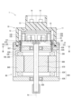
- FIG. 2 is a cross-sectional view of a drive device according to a first embodiment;
- FIG. 3 is a cross-sectional view taken along line III-III in FIG. 2;
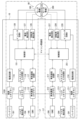
- FIG. 4 is a block diagram showing a configuration of an ECU according to a first embodiment;
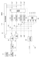
- FIG. 5 is a block diagram showing a current control unit of the first control unit according to the first embodiment;
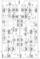
- FIG. 6 is a block diagram showing a current control unit of a first control unit and a second control unit according to a first embodiment;
- FIG. 1 is a schematic diagram of an electric power steering device according to a first embodiment.
- FIG. 2 is a cross-sectional view of a drive device according to a first embodiment;
- FIG. 3 is a cross-sectional view taken along line III-III in FIG. 2;
- FIG. 4 is a block diagram showing a configuration of an ECU according to a first embodiment;
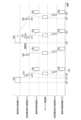
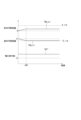
- FIG. 7 is a time chart illustrating a current control process according to a reference example.
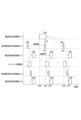
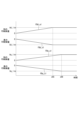
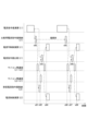
- FIG. 8 is a time chart illustrating the current control process according to the first embodiment.
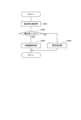
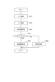
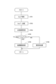
- FIG. 9 is a flowchart illustrating a current control process according to the first embodiment.
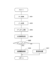
- FIG. 10 is a flowchart illustrating a current control process according to the second embodiment.
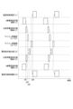
- FIG. 11 is a time chart illustrating a current control process according to the second embodiment.
- FIG. 12 is a time chart illustrating a current control process according to the second embodiment.
- FIG. 13 is a time chart illustrating a current control process according to the second embodiment.
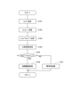
- FIG. 14 is a flowchart illustrating a set constant transmission process according to the third embodiment.
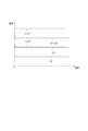
- FIG. 15 is a time chart showing a current detection value and a current command value.
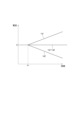
- FIG. 16 is a time chart showing the feedback control amount of the first control unit when the current command value is different;
- FIG. 17 is a time chart showing the feedback control amount of the second control unit when the current command value is different;
- FIG. 18 is a time chart showing a voltage command value when the limit values of the sum feedback control amount and the difference feedback control amount are different.
- FIG. 19 is a time chart showing a current when the limit values of the sum feedback control amount and the difference feedback control amount are different.
- FIG. 20 is a flowchart illustrating the FB control amount limiting process according to the fourth embodiment.
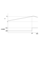
- FIG. 21 is a time chart showing an FB control amount and a voltage command value according to the fourth embodiment;
- FIG. 22 is a time chart showing an FB control amount according to the fourth embodiment;
- FIG. 23 is a time chart showing the feedback control amount according to the fourth embodiment;
- FIG. 24 is a flowchart illustrating an abnormality determination process according to the fifth embodiment.
- FIG. 25 is a time chart illustrating a transition to an abnormality procedure according to the fifth embodiment.
- FIG. 26 is a flowchart illustrating an abnormality determination process according to a sixth embodiment.
- FIG. 27 is a flowchart illustrating a command value comparison process in a first control unit according to a seventh embodiment;
- FIG. 28 is a flowchart illustrating a command value comparison process in a second control unit according to a seventh embodiment;
- FIG. 29 is a time chart illustrating a command value comparison process according to the seventh embodiment.
- FIG. 30 is a time chart illustrating the command value comparison process according to the seventh embodiment.
- FIG. 31 is a flowchart illustrating a command value comparison process in a first control unit according to an eighth embodiment
- FIG. 32 is a flowchart illustrating a command value comparison process in a second control unit according to an eighth embodiment
- FIG. 33 is a time chart illustrating a command value comparison process according to the eighth embodiment
- FIG. 34 is a flowchart illustrating a command value comparison process in a first control unit according to a ninth embodiment
- FIG. 35 is a flowchart illustrating a command value comparison process in a second control unit according to a ninth embodiment
- FIG. 35 is a time chart illustrating a command value comparison process according to the ninth embodiment
- FIG. 37 is a flowchart illustrating a set constant comparison process in the first control unit according to the tenth embodiment
- FIG. 38 is a flowchart illustrating a set constant comparison process in the first control unit according to the tenth embodiment.
- an ECU 10 as a rotating electric machine control device is applied to, for example, an electric power steering device 8 for assisting the steering operation of a vehicle together with a motor 80 as a rotating electric machine.
- FIG. 1 shows the overall configuration of a steering system 90 equipped with an electric power steering device 8.
- the steering system 90 includes a steering wheel 91, which is a steering member, a steering shaft 92, a pinion gear 96, a rack shaft 97, wheels 98, and the electric power steering device 8.
- the steering wheel 91 is connected to a steering shaft 92.
- a torque sensor 94 that detects steering torque is provided on the steering shaft 92.
- the torque sensor 94 has a first torque detection unit 194 and a second torque detection unit 294, and the sensors are duplicated so that each can detect its own failure.
- a pinion gear 96 is provided at the tip of the steering shaft 92.
- the pinion gear 96 meshes with a rack shaft 97.
- a pair of wheels 98 are connected to both ends of the rack shaft 97 via tie rods or the like.
- the steering shaft 92 connected to the steering wheel 91 rotates.
- the rotational motion of the steering shaft 92 is converted into linear motion of a rack shaft 97 by a pinion gear 96.
- a pair of wheels 98 are steered to an angle that corresponds to the amount of displacement of the rack shaft 97.
- the electric power steering device 8 includes a drive unit 1 and a reduction gear 89, which is a power transmission unit.
- the drive unit 1 has a motor 80 and an ECU 10.
- the drive unit 1 is a so-called "mechatronically integrated type" in which the ECU 10 is integrally provided on one side of the motor 80 in the axial direction, but the motor 80 and the ECU 10 may be provided separately.
- the ECU 10 is arranged coaxially with the axis Ax of the shaft 870 on the opposite side to the output shaft of the motor 80.
- the ECU 10 may be arranged on the output shaft side of the motor 80.
- the reduction gear 89 reduces the speed of the rotation of the motor 80 and transmits it to the steering shaft 92, which is the object to be driven.
- the electric power steering device 8 of this embodiment is a so-called “column assist type", but it may also be a so-called “rack assist type” in which the rotation of the motor 80 is transmitted to a rack shaft 97.
- the motor 80 outputs some or all of the torque required for steering, and has two sets of motor windings 180, 280.
- the motor 80 is supplied with power from batteries 191, 291 (see Figure 4) as a power source, and is driven by controlling the current flow to the motor windings 180, 280, causing the reduction gear 89 to rotate forward and reverse.
- the motor 80 is a three-phase brushless motor, and includes a stator 840, a rotor 860, and a housing 830 that accommodates these.
- the combination of configurations related to the energization control of the first motor winding 180 will be referred to as the first system L1
- the combination of configurations related to the energization control of the second motor winding 280 will be referred to as the second system L2
- the configurations related to the first system L1 being numbered mainly in the 100s
- the configurations related to the second system L2 being numbered mainly in the 200s.
- the configurations related to the first control unit 151 of the first system L1 will be numbered in the 500s
- the configurations related to the second control unit 251 of the second system L2 will be numbered in the 600s.
- the housing 830 has a cylindrical case 834 with a bottom, which includes a rear frame end 837, and a front frame end 838 provided on the opening side of the case 834.
- the case 834 and the front frame end 838 are fastened to each other with bolts or the like.
- a lead wire insertion hole 839 is formed in the rear frame end 837.
- the stator 840 is fixed to the housing 830, and the motor windings 180, 280 are wound around it.
- the lead wires 185, 285 connected to each phase of the motor windings 180, 280 are inserted through the lead wire insertion holes 839, taken out to the ECU 10 side, and connected to the board 20.
- the rotor 860 is provided radially inside the stator 840.
- a magnet is provided radially outside the stator 840 and is rotatable relative to the stator 840.
- Shaft 870 is fitted into rotor 860 and rotates integrally with rotor 860.
- Shaft 870 is rotatably supported in housing 830 by bearings 835 and 836.
- the end of shaft 870 on the ECU 10 side protrudes from housing 830 towards the ECU 10 side.
- a magnet 875 is provided at the end of shaft 870 on the ECU 10 side.
- the ECU 10 includes a cover 11, a heat sink 15 fixed to the cover 11, a circuit board 20 fixed to the heat sink 15, and various electronic components mounted on the circuit board 20.
- the cover 11 protects the electronic components from external impacts and prevents dust, water, etc. from entering the inside of the ECU 10.
- the cover 11 is formed integrally with the cover body 12 and the connector section 13.
- the connector section 13 may be separate from the cover body 12.
- the connector section 13 includes power connectors 111, 211, vehicle communication connectors 112, 212, and torque connectors 113, 213, which will be described later.
- the connector terminals 14 are connected to the board 20.
- the connector section 13 is provided for each system, has two openings, and opens on the side opposite the motor 80. The number and orientation of the openings, the number of terminals, etc. can be changed as appropriate.
- the board 20 is, for example, a printed circuit board, and is provided opposite the rear frame end 837. Two systems of electronic components are mounted on the board 20, with separate areas for each system. In this embodiment, the electronic components are mounted on a single board 20, but the electronic components may be mounted on multiple boards.
- the board 20 may also be fixed to the motor 80 side (for example, the rear frame end 837).
- the surface facing the motor 80 is referred to as the motor surface 21, and the surface opposite the motor 80 is referred to as the cover surface 22.
- the motor surface 21 is equipped with the switching element 121 that constitutes the inverter circuit 120, the switching element 221 that constitutes the inverter circuit 220, the rotation angle detection units 126, 226, the custom ICs 135, 235, etc.
- the rotation angle detection units 126, 226 are mounted at locations facing the magnet 875 so that they can detect changes in the magnetic field that accompany the rotation of the magnet 875.
- Capacitors 128, 228, inductors 129, 229, and microcomputers constituting control units 151, 251 are mounted on cover surface 22.
- the microcomputers constituting control units 151, 251 are numbered "151" and "251", respectively.
- Capacitors 128, 228 smooth the power input from batteries 191, 291.
- Capacitors 128, 228 also assist in the power supply to motor 80 by storing electric charge.
- Capacitors 128, 228 and inductors 129, 229 form a filter circuit that reduces noise transmitted from other devices that share batteries 191, 291, and reduces noise transmitted from drive unit 1 to other devices that share batteries 191, 291.
- the power supply relay, motor relay, and current detection units 127, 227, etc. are also mounted on the motor surface 21 or the cover surface 22.
- the ECU 10 includes inverter circuits 120, 220, and control units 151, 251, etc.
- the ECU 10 is provided with power connectors 111, 211, vehicle communication connectors 112, 212, and torque connectors 113, 213.
- the first power connector 111 is connected to a first battery 191, and the second power connector 211 is connected to a second battery 291.
- the power connectors 111, 211 may be connected to the same battery.
- the first power connector 111 is connected to the first inverter circuit 120 via a first power supply circuit 116.
- the second power connector 211 is connected to the second inverter circuit 220 via a second power supply circuit 216.
- the power supply circuits 116, 216 include, for example, a power supply relay, etc.
- the vehicle communication connector 112 is connected to the vehicle communication network 195, and the vehicle communication connector 212 is connected to the vehicle communication network 295.
- the vehicle communication connectors 112, 212 are connected to separate vehicle communication networks 195, 295, respectively, but may be connected to the same vehicle communication network.
- CAN Controller Area Network
- CAN-FD CAN with Flexible Data rate
- FlexRay FlexRay
- the torque connectors 113 and 213 are connected to the torque sensor 94.
- the first torque connector 113 is connected to the first torque detection unit 194.
- the second torque connector 213 is connected to the second torque detection unit 294.
- the first control unit 151 can obtain a torque signal related to the steering torque Ts from the first torque detection unit 194 via the torque connector 113 and the torque sensor input circuit 118.
- the second control unit 251 can obtain a torque signal related to the steering torque Ts from the second torque detection unit 294 via the torque connector 213 and the torque sensor input circuit 218. This allows the control units 151 and 251 to calculate the steering torque Ts based on the torque signal.
- the first inverter circuit 120 is a three-phase inverter having six switching elements 121, and converts the power supplied to the first motor winding 180.
- the on/off operation of the switching elements 121 is controlled based on a control signal output from the first control unit 151.
- the second inverter circuit 220 is a three-phase inverter having six switching elements 221, and converts the power supplied to the second motor winding 280.
- the on/off operation of the switching elements 221 is controlled based on a control signal output from the second control unit 251.
- the first current detection unit 127 detects the current flowing through each phase of the first motor winding 180 and outputs the detection value to the first control unit 151.
- the second current detection unit 227 detects the current flowing through each phase of the second motor winding 280 and outputs the detection value to the second control unit 251.
- the first rotation angle detection unit 126 detects the rotation angle of the motor 80 and outputs the detection value to the first control unit 151.
- the second rotation angle detection unit 226 detects the rotation angle of the motor 80 and outputs the detection value to the second control unit 251.
- the control units 151 and 251 are mainly composed of a microcomputer and include a CPU, ROM, RAM, I/O, and bus lines connecting these components (none of which are shown). Each process in the control units 151 and 251 may be software processing in which the CPU executes a program prestored in a physical memory device such as a ROM (i.e., a readable non-transitory tangible recording medium), or may be hardware processing using a dedicated electronic circuit.
- the first control unit 151 and the second control unit 251 are arranged to be able to communicate with each other.
- inter-microcomputer communication Any communication method may be used, such as serial communication such as SPI or SENT, CAN communication, or FlexRay communication. The same applies to each control unit in the embodiments described below.
- FIG. 5 shows the current control of this embodiment
- Figure 5 shows the first control unit 151
- the second control unit 251 is omitted.
- the transmitters 171, 271 and the receivers 172, 272 are appropriately separated and described.
- the description of the second control unit 251, such as the d-axis current calculation will be omitted as appropriate, and the first control unit 151 will be used as an example for the description, where similar points are obtained by replacing the values of the first system L1 with the values of the second system L2.
- the first system L1 will be described as the main system, and the second system L2 as the sub system.
- the terms “main” and “sub” are used to distinguish which command is used preferentially, but the output is equivalent.
- the first system L1 will be referred to as the main system and the second system L2 as the sub system, and control that coordinates the first system L1 and the second system L2 will be referred to as "cooperative drive control", control that drives the first system L1 and the second system L2 without coordinating them will be referred to as “independent drive control”, and control that drives either the first system L1 or the second system L2 will be referred to as "single system drive control".
- the first control unit 151 has an energization control unit 500, an abnormality determination unit 560, a warning unit 565, a transmission unit 171, and a reception unit 172.
- the energization control unit 500 controls the energization of the first motor winding 180, and includes an electrical angle calculation unit 506, a detected current calculation unit 507, a torque command calculation unit 511, a basic command calculation unit 512, a torque d-axis current command calculation unit 519, a field weakening calculation unit 521, a field weakening d-axis current command arbitration unit 522, a d-axis current command calculation unit 525, a q-axis current command calculation unit 526, a current control calculation unit 530, and a PWM output unit 555.
- the second control unit 251 has an energization control unit 600, an abnormality determination unit 660, a warning unit 665, a transmission unit 271, and a reception unit 272.
- the energization control unit 600 controls the energization of the second motor winding 280, and includes an electrical angle calculation unit 606, a detected current calculation unit 607, a torque command calculation unit 611, a basic command calculation unit 612, a torque d-axis current command calculation unit 619, a field weakening calculation unit 621, a field weakening d-axis current command arbitration unit 622, a d-axis current command calculation unit 625, a q-axis current command calculation unit 626, a current control calculation unit 630, and a PWM output unit 655.
- the transmitting unit 171 stores values calculated by the first control unit 151 and transmits the stored values at the communication timing to the second control unit 251.
- the receiving unit 172 receives values transmitted from the second control unit 251.
- the transmitting unit 271 stores values calculated by the second control unit 251 and transmits the values stored at the communication timing to the first control unit 151.
- the receiving unit 272 receives values transmitted from the first control unit 151.
- the electrical angle calculation unit 506 calculates the electrical angle ⁇ e1 based on the detection value of the rotation angle detection unit 126.
- the detected current calculation unit 507 calculates the phase currents Iu1, Iv1, Iw2 based on the detection value of the current detection unit 127.
- the detected current calculation unit 507 also performs dq conversion on the phase currents Iu1, Iv1, Iw1 using the electrical angle ⁇ e1 to calculate the d-axis current detection value Id1 and the q-axis current detection value Iq1.
- dq axes when the d-axis and q-axis values are referred to together, they will be referred to as "dq axes".
- the dq-axis current detection values Id1 and Iq1 are used for current control calculations in the own system, and are also sent to the second control unit 250 via inter-microcomputer communication and are used for current control in other systems.
- the sum/difference calculation unit 508 acquires the d-axis and q-axis current detection values Id1 and Iq1 of the first system L1 and the d-axis and q-axis current detection values Id2 and Iq2 of the second system L2.
- the sum/difference calculation unit 508 calculates the d-axis current sum Id_a, which is the sum of the d-axis current detection values Id1 and Id2, the d-axis current difference Id_s, which is the difference between the d-axis current detection values Id1 and Id2, the q-axis current sum Iq_a, which is the sum of the q-axis current detection values Iq1 and Iq2, and the q-axis current difference Iq_s, which is the difference between the q-axis current detection values Iq1 and Iq2.
- the torque current calculation unit 509 calculates the torque current detection value I_trq1 based on the d-axis current sum Id_a and the q-axis current sum Iq_a. In this embodiment, the output torque of the motor 80 is monitored by monitoring the torque current detection value I_trq1.
- a torque command calculation unit 511 calculates a torque command value Trq1 * based on the steering torque, vehicle speed, etc.
- a basic command calculation unit 512 has a torque current command calculation unit 513, a current limit calculation unit 515, a current limit arbitration unit 516, and a current limiting unit 517, and calculates a basic current command value Ib1 * .
- a basic command calculation unit 612 has a torque current command calculation unit 613, a switching unit 614, a current limit calculation unit 615, a current limit arbitration unit 616, and a current limiting unit 617, and calculates a basic current command value Ib2 * .
- the torque current command calculation units 513, 613 calculate torque current command values Itrq1 * , Itrq2 * based on the torque command values Trq1 * , Trq2 * by, for example, multiplying them by a predetermined coefficient.
- the first torque current command value Itrq1 * is transmitted to the second control unit 251.
- the switching unit 614 can switch between the torque current command values Itrq1 * and Itrq2 * used for control.
- the switching unit 614 uses the first torque current command value Itrq1 * during cooperative drive control, and selects the second torque current command value Itrq2 * during independent drive control or single-system drive control in the second system L2.
- the current limit calculation unit 515 calculates a current limit value Ilim1 for overheat protection and the like.
- the current limit value Ilim1 is sent to the second control unit 251.
- the first control unit 151 also obtains the current limit value Ilim2 calculated by the second control unit 251.
- the current limit arbitration unit 516 calculates the arbitrated current limit value Ilim_m1 based on the current limit value Ilim1 of the own system and the current limit value Ilim2 of the other system. In this embodiment, the smaller of the current limit value Ilim1 of the own system or the current limit value Ilim2 of the other system is set as the arbitrated current limit value Ilim_m1 in minimum selection.
- the current limiting unit 517 calculates the smaller value of the torque current command value Itrq1 * and the arbitrated current limit value Ilim_m1 as a base current command value Ib1 * .
- the current limiting unit 617 calculates the smaller value of the torque current command value selected by the switching unit 614 as a base current command value Ib2 * based on the arbitrated current limit value Ilim_m2 and the torque current command value Itrq1*.
- the torque d-axis current command calculation unit 519 calculates a torque d-axis current command value Id_t1 * based on the basic current command value Ib1 * by map calculation or the like.
- the field weakening calculator 521 calculates a pre-limitation field weakening d-axis current command value Id_wb1 * based on the current limit value Ilim1, the saturation value for the maximum applied voltage, and the modulation rate of the voltage command value.
- the field weakening calculator 521 also obtains the q-axis current sum Iq_a from the sum-difference calculator 508, and calculates a field weakening d-axis current limit value Id_lim_w1 based on the q-axis current sum Iq_a.
- the field weakening calculator 521 sets the smaller absolute value as the field weakening d-axis current command value Id_w1 * based on the pre-limitation field weakening d-axis current command value Id_wb1 * and the field weakening d-axis current limit value Id_lim_w1.
- the field weakening d-axis current command value Id_w1 * is transmitted to the second controller 251.
- the first control unit 151 acquires the field weakening d-axis current command value Id_w2 * calculated by the second control unit 251.
- the field weakening d-axis current command arbitration unit 522 calculates the arbitration-post field weakening d-axis current command value Id_wm1 * based on the field weakening d-axis current command value Id_w1 * of the own system and the field weakening d-axis current command value Id_w2* of the other system.
- the arbitration-post field weakening d-axis current command value Id_wm1 * is calculated by minimum select. It should be noted that if the d-axis current is a negative value, the value with the larger absolute value is selected by minimum select. The same applies to minimum select for other d-axis currents. For simplification, in FIG.
- the description of the field weakening d-axis current command arbitration unit 522 is omitted, and the field weakening d-axis current command value Id_w1 * of the own system is described as being input to the d-axis current command calculation unit 525.
- the d-axis current command calculation unit 525 calculates the d-axis current command value Id1 * by minimum selection based on the torque d-axis current command value Id_t1 * and the arbitration weakening field d-axis current command value Id_wm1 * .
- the q-axis current command calculation unit 526 calculates the q-axis current command value Iq1 * by, for example, map calculation based on the basic current command value Ib1 * and the d-axis current command value Id1 * .
- the current control calculation unit 530 calculates current sum command values Id_a * , Iq_a * and current difference command values Id_s * , Iq_s * based on the current command values Id1 * , Iq1 * , etc. As shown in Fig. 5, the current control calculation unit 530 has subtractors 531 to 534, current feedback control units 541 to 544, a voltage command calculation unit 550, etc.
- the subtractor 531 subtracts the d-axis current sum Id_a from the d-axis current sum command value Id_a * to calculate the d-axis current sum deviation ⁇ Id_a.
- the subtractor 532 subtracts the q-axis current sum Iq_a from the q-axis current sum command value Iq_a * to calculate the q-axis current sum deviation ⁇ Iq_a.
- the subtractor 533 subtracts the d-axis current difference Id_s from the d-axis current difference command value Id_s * to calculate the d-axis current difference deviation ⁇ Id_s.
- the subtractor 534 subtracts the q-axis current difference Iq_s from the q-axis current difference command value Iq_s * to calculate the q-axis current difference deviation ⁇ Iq_s.
- the current feedback control units 541 to 544 respectively calculate the sum FB control amounts FBd_a and FBq_a and the difference FB control amounts FBd_s and FBq_s by, for example, PI calculation so that the d-axis current sum deviation ⁇ Id_a, the q-axis current sum deviation ⁇ Iq_a, the d-axis current difference deviation ⁇ Id_s, and the q-axis current difference deviation ⁇ Iq_s converge to 0.
- the voltage command calculation unit 550 calculates the voltage command values Vd1 * , Vq1 * , Vd2 * , and Vq2 * based on the FB control amounts FBd_a, FBq_a, FBd_s, and FBq_s. That is, in the cooperative drive control of this embodiment, "sum and difference control" is performed to control the current sum and current difference of the two systems. This makes it possible to cancel the effect of mutual inductance.
- the PWM output unit 555 generates PWM signals based on three-phase voltage commands Vu1 * , Vv1 * , and Vw1 * obtained by inverse dq conversion of the voltage command values Vd1 * and Vq1 * .
- the PWM signals are synchronized by, for example, a synchronization signal so that the signal timings of the systems are aligned.
- the synchronization signal may be transmitted from one system to the other, or may be acquired by both systems from the outside.
- the abnormality determination unit 560 determines abnormalities in the current detection value, etc. If an abnormality is detected, abnormality measures are taken. When abnormality measures are taken, the warning unit 565 warns the driver of the abnormality by a warning lamp or the like. The warning to the driver is not limited to lighting up the warning lamp, but may also be a display or audio warning. Details of abnormality determination and abnormality measures will be described in the embodiment described later.
- the second system L2 performs current control using a current command value transmitted from the first system L1 by inter-microcomputer communication.
- the current command value transmitted from the first system L1 is a first torque current command value Itrq1 * , but in the following, for the sake of simplicity of explanation, the current command value commonly used by the control units 151 and 251 in the cooperative drive control is referred to as a current command value I * .
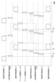
- FIG. 7 etc. the top three rows are processing in the first control unit 151, the bottom two rows are processing in the second control unit 251, and "(L1)” in the figure indicates processing in the first control unit 151, and “(L2)” indicates processing in the second control unit 251.
- Calculated values are also written as appropriate, such as " ⁇ Ca>", and the exchange of calculated values is indicated by dashed arrows.
- FIG. 7 and FIG. 8 show an example in which the current FB calculation period (e.g., 200 ⁇ s) is shorter than the command calculation period (e.g., 400 ⁇ s).
- Time x12 is the timing for updating stored data in the inter-microcomputer communication that starts at time x13.
- the current command value I * transmitted from the first control unit 151 to the second control unit 251 at time x13 is stored in the reception unit 272 at time x14.
- the values of the current command values I * in the current control calculation units 530 and 630 are both Ca, and the current FB calculation is performed using the same value.
- the current command value calculation from time x16 if the calculation of the current command value I * does not arrive in time for time x17, which is the timing for updating stored data in the inter-microcomputer communication, due to an increase in the calculation load or the like, the previous value Ca is held in the transmitting unit 171, and at time x18, the value Ca is transmitted as the current command value I * to the second control unit 251.
- the second control unit 251 performs a current FB calculation using the value Ca as the current command value I * .
- the current FB control will be performed with different command values in the control units 151 and 251. If the current command value I * differs between the systems, the voltage command value will increase, and there is a risk of an abnormal current occurring.
- the first control unit 151 uses the value stored in the transmission unit 171 for the current FB calculation.
- the value Ca calculated by the current command calculation in the first control unit 151 from time x20 to time x21 is stored in the transmission unit 171 at time x22, and is transmitted to the second control unit 251 by inter-microcomputer communication at time x23.
- the processing on the second control unit 252 side is the same as that in Fig. 7.
- the first control unit 151 performs a current FB calculation using the value Ca stored in the transmission unit 171 as the current command value I * .
- the first control unit 151 performs the current FB calculation using the value Ca as the current command value I * . That is, although the calculation of the current command value I * is completed at time x32, the first control unit 151 performs the current FB calculation using the previous value Ca stored in the transmission unit 171, rather than the value Cb calculated at time x32, in order to match the value used with the second control unit 251.
- the value Cb calculated at time x32 is stored in the transmitting unit 171 as the current command value I * , and at time x35 is transmitted to the second control unit 251.
- both of the control units 151 and 251 perform current FB control using the value Cb as the current command value I * .
- step S101 the steps will simply be referred to as "S".
- the first control unit 151 calculates a current command value I * .
- the first control unit 151 updates the data of the transmission unit 171 at a predetermined update timing. Here, if the current command calculation is not completed, the previous value is held.
- the first control unit 151 transmits the data stored in the transmission unit 171 to the second control unit 251 by inter-microcomputer communication.
- the first control unit 151 performs a current FB control calculation using the current command value I * stored in the transmission unit 171.
- the first control unit 151 performs current FB calculations using values stored in the transmission unit 171. This allows the control units 151 and 251 to perform current feedback calculations using the same values even if the calculation of the current command value I * does not arrive in time for the inter-microcomputer communication timing.
- the ECU 10 controls the driving of the motor 80 having multiple sets of motor windings 180, 280, and includes multiple control units 151, 251.
- the control units 151, 251 have current control units 500, 600, which are provided for each motor winding 180, 280 and can communicate with each other.
- the current control units 500, 600 calculate a voltage command value to be applied to the motor windings 180, 280 based on the current detection value and current command value of the current flowing through the motor windings 180, 280, and control the current flow through the motor windings 180, 280 based on the voltage command value.
- the ECU 10 can perform cooperative drive control in which a combination of the motor windings 180, 280 and the corresponding control units 151, 251 is treated as a system, and at least one parameter is shared between the systems to perform energization control.
- the parameters include a current command value, a current detection value, etc., and may include command values and detection values other than current.
- the current detection values Id1, Iq1, Id2, Iq2, and the torque current command value Itrq1 *, etc. are shared in the cooperative drive control.
- the second control unit 251 controls the energization of the motor windings 280 using the current command value I * transmitted from the first control unit 151.
- the first control unit 151 controls the energization of the motor windings 180 using the same current command value I * transmitted to the second control unit 251.
- the first control unit 151 has a transmission unit 171 capable of storing a current command value I * to be transmitted to the second control unit 251, and controls energization of the motor windings 180 using the current command value I * stored in the transmission unit 171.
- the first control unit 151 can perform a current FB control calculation using the same value as the value transmitted to the second control unit 251.
- the second embodiment is shown in Fig. 10 to Fig. 13.
- the current control process of this embodiment will be described based on the flowchart in Fig. 10.
- the calculation timing will be appropriately indicated by the subscript (n), (n-1), etc.
- the first control unit 151 calculates the current command value I * , similarly to S101.
- the first control unit 151 judges whether the current value I * (n) stored in the transmission unit 171 is different from the previous value I * (n-1) . If it is judged that the current value I * (n) is equal to the previous value I * (n-1) (S122: NO), S123 is skipped and the value of the transmission unit 171 is not updated. If it is judged that the current value I * (n) is different from the previous value I * (n-1) (S122: YES), the process proceeds to S123 and the data of the transmission unit 171 is updated at a predetermined update timing. In S124, the control unit 151 transmits the data stored in the transmission unit 171 to the second control unit 251 by inter-microcomputer communication.
- the first control unit 151 judges whether the current command value I * stored in the transmission unit 171 has been updated. If it is judged that the current command value I * of the transmission unit 171 has been updated (S125: YES), the process proceeds to S126, where the current command value I * is updated and a current FB control calculation is performed. If it is judged that the current command value I * of the transmission unit 171 has not been updated (S124: NO), the process proceeds to S127, where the current command value I1 * is not updated and a current FB control calculation is performed.
- Time charts for explaining the current control process are shown in Figures 11 to 13.
- the value of the current command value I * calculated by the first control unit 151 is Cb, which is different from the value Ca stored in the transmission unit 171, so the value Cb is stored in the transmission unit 171 at time x42, which is the timing for updating the stored data in the inter-microcomputer communication.
- the current command value I * is transmitted to the second control unit 251 through inter-microcomputer communication.
- the first control unit 151 performs a current FB calculation using the value Cb, since the current command value I * stored in the transmission unit 171 has been updated to the value Cb.
- the control units 151 and 251 perform a current FB control calculation using the same value Cb.
- the current command value I * stored in the transmission unit 171 is updated to the value Cb whose calculation was completed at time x53, and is transmitted to the second control unit 251 at time x56.
- the second control unit 252 performs a current FB calculation using the value Cb as the current command value I * .
- the first control unit 151 updates the current command value I * to the value Cb and performs a current FB control calculation.
- the first control unit 151 determines the update status of the current command value I * stored in the transmission unit 171, and if the value has been updated, updates the current command value I * used in the current FB control calculation. If the current command value I * stored in the transmission unit 171 has not been updated, the current command value I * used in the current FB calculation is not updated, and the current FB calculation is performed with the previous value. This allows the control units 151 and 251 to perform the current FB calculation using the same value.
- the first control unit 151 holds the previous value as the current command value and controls the current supply to the motor windings 180.
- the first control unit 151 also performs a current FB control calculation using the previous value without updating the current command value I * , so that it is possible to prevent the occurrence of abnormal current due to deviation of command values between systems.
- the same effects as those of the above embodiment are achieved.
- the third embodiment is shown in Fig. 14.
- the control units 151 and 251 perform current feedback control using the same value as the current command value I * .
- the current command value I * is the same, if the setting constants used in the current feedback control are different, the voltage command value as the current feedback control calculation result will be different, and there is a risk of an abnormal current occurring.
- the first control unit 151 has all the setting constants, and the second control unit 251 performs current control calculations using the setting constants sent from the first control unit 151.
- the setting constants include, for example, a current limit value, a PI gain, and an abnormality determination threshold value.
- the second control unit 251 may be configured to have the setting constants, and the second control unit 251 may be configured to send the setting constants to the first control unit 151.
- the setting constant transmission process of this embodiment will be described with reference to the flowchart in FIG. 14. This process is performed, for example, at the time of the initial check when the ECU 10 is started, but it may be performed at any time other than the initial check. The same applies to the tenth embodiment.
- the first control unit 151 transmits a setting constant to the second control unit 251.
- the second control unit 251 receives the setting constant from the first control unit 151.
- the second control unit 251 stores the received setting constant in a storage unit (not shown).
- one control unit 151 transmits a setting constant, which is a constant used in the current control calculation, to the other control unit 251.
- the setting constant is stored in only one control unit 151, and the setting constant is shared with the other control unit 251. This allows the control units 151 and 251 to perform current control calculations using the same setting constant, preventing deviations in the calculation values due to differences in the setting constant. It also provides the same effects as the above embodiment.
- Fourth Embodiment 15 to 23 show the fourth embodiment.
- the current command value I * is common to the control units 151 and 251.
- the current command value I * is different between the control units 151 and 251 will be described.
- the current FB control calculation will be explained using the q-axis current as an example.
- the q-axis current detection value of the first system L1 is Iq1
- the q-axis current detection value of the second system L2 is Iq2
- the q-axis current sum Iq_a is equation (1)
- the q-axis current difference Iq_s is equation (2).
- the current difference command value is 0 and the current detection value is stable, the current sum command value and the current sum match.
- the current detection values Iq1 and Iq2 are expressed by equations (3) and (4) from the current sum and current difference.
- equations (5) to (7) are obtained, and the slopes of the FB control amounts FBq_a1, FBq_a2, FBq_s1, and FBq_s2 are all the same. That is, in the first system L1, the sum FB control amount FBq_a1 and the difference FB control amount FBq_s1 increase by the same amount in opposite directions, and in the second system L2, the sum FB control amount FBq_a2 and the difference FB control amount FBq_s2 increase by the same amount in the same direction. Also, when the sum FB control amount and the difference FB control amount change in the same way, the voltage command value does not change.
- the voltage command value Vq1 * of the first system L1 is expressed by equation (8)
- the voltage command value Vq2 * of the second system L2 is expressed by equation (9).
- Vq1 * (FBq_a1+FBq_s1)/2 ...
- Vq2 * (FBq_a2 - FBq_s2)/2 ...
- the horizontal axis is time, with Fig. 15 showing the current command value and current detection value, Fig. 16 showing the sum and difference FB control amount of the first control unit 151, and Fig. 17 showing the sum and difference FB control amount of the second control unit 251.
- Fig. 15 shows the current command value Iq_a1 * and current detection value Iq1 of the first control unit 151 are different from the Iq_a2 * and current detection value Iq2 of the second control unit 251.
- the q-axis current sum Iq_a which is the detected value, is smaller than the current sum command value Iq_a1 * , so the sum FB control amount FBq_a1 is calculated to increase the current sum.
- the q-axis current sum Iq_a is larger than the current sum command value Iq_a2 * , so the sum FB control amount FBq_a2 is calculated to decrease the current sum.
- a difference occurs between the current detection values Iq1 and Iq2, so the difference FB control amounts FBq_s1 and FBq_s2 are calculated to decrease the current difference.
- the current control calculation units 530 and 630 upper and lower limits of the FB control amount are guarded to prevent control overflow. If the limit value of the sum of the FB control amount is A_lim and the limit value of the difference of the FB control amount is S_lim, the sum limit value A_lim and the difference limit value S_lim may be made different from each other, for example, the sum limit value A_lim is set to be larger than the difference limit value S_lim so that the output when one system is driven is as desired.
- the voltage command value Vq1 * increases with an increase in the sum FB control amount FBq_a1.
- the current detection values Iq1, Iq2 increase with an increase in the voltage command values Vq1 * , Vq2 * , there is a risk of an overcurrent occurring.
- the current control calculation units 530, 630 determine whether the differential FB control amount FBq_s is limited by the difference limit value S_lim. If it is determined that the differential FB control amount FBq_s is not limited by the difference limit value S_lim (S301: NO), the process proceeds to S302, and the current calculation value is used as the sum FB control amount FBq_a. If it is determined that the differential FB control amount FBq_s is limited by the difference limit value S_lim (S301: YES), the process proceeds to S303, and the previous value is held as the sum FB control amount FBq_a.
- the first system L1 is taken as an example, the horizontal axis is a common time axis, and from the top, the sum FB control amount FBq_a1, the difference FB control amount FBq_s1, and the voltage command value Vq1 * are shown.
- and the difference FB control amount FBq_s1 is limited by the difference limit value -S_lim at time x60, the sum FB control amount FBq_a1 holds the previous value. This holds the voltage command value Vq1 * , making it possible to prevent overcurrent.
- the limit values need only be consistent for the d-axis sum and difference, and the q-axis sum and difference, and may be equal or different for the d-axis and q-axis values.
- the first system L1 is used as an example, the horizontal axis is a common time axis, and from the top, the d-axis sum FBd_a1, the difference FB control amount FBs_s1, the q-axis sum FB_a1, and the difference FBq_s1 are shown.
- the d-axis sum limit value is Ad_lim
- the d-axis difference limit value is Sd_lim
- the q-axis sum limit value is Aq_lim
- the q-axis difference limit value is Sq_lim.
- the limit value Sd_lim of the d-axis difference and the limit value Sq_lim of the q-axis difference are different, with Sd_lim ⁇ Sq_lim.
- the FB control amount FBd_s1 of the d-axis difference is limited by the limit value Sd_lim, so the previous value is held for the sum FB control amount FBd_a1.
- the FB control amount FBq_s1 of the q-axis difference is limited by the limit value Sq_lim, so the previous value is held for the sum FB control amount FBq_a1.
- the current control units 500, 600 in current feedback control using the current sum and current difference between the current detection value of the own system and the current detection value of the other system, limit the upper and lower limits of the sum FB control amount FB_a, which is the feedback calculation result based on the current sum, and the difference FB control amount FB_s, which is the feedback calculation result based on the current difference.
- the upper and lower limits are limited so that the sum FB control amount FB_a and the difference FB control amount FB_s are limited simultaneously.
- “simultaneously” means that an error is allowed to the extent that the balance is not lost and a large current is not generated. This makes it possible to prevent control overflow.
- the current control units 500, 600 hold the previous value for the other of the sum FB control amount FB_a or the difference FB control amount FB_s.
- the sum limit value A_lim and the difference limit value S_lim are set to different values, during cooperative drive control, it is possible to simultaneously limit the sum FB control amount FB_a and the difference FB control amount FB_s, and overcurrent can be prevented.
- the sum limit value A_lim that limits the upper and lower limits of the sum FB control amount FB_a and the difference limit value S_lim that limits the upper and lower limits of the difference FB control amount FB_s may be set equal. This prevents the balance between the sum and difference FB control amounts from being lost, and can prevent overcurrent. This also provides the same effects as the above embodiment.
- FIG. 24 and Fig. 25 A fifth embodiment is shown in Fig. 24 and Fig. 25.
- the first system L1 is mainly described as an example, focusing on abnormality treatment.
- the q-axis current detection value Iq1 of the first system L1 increases in the positive direction and the q-axis current detection value Iq2 of the second system L2 increases in the negative direction, the sum of these values becomes 0, and it may appear that no large current is flowing (see Fig. 19).
- the balance is lost, the large current will become apparent, which may lead to a breakdown of the controlled object.
- abnormality determination unit 560 acquires the current detection values Id1, Iq1, Id2, and Iq2 of each system.
- the abnormality determination unit 560 determines whether the current detection values Id1, Iq1, Id2, and Iq2 of each system are smaller than the current abnormality determination threshold THi.
- the determination is made in absolute values.
- the current abnormality determination threshold THi may be equal to or different from the value related to the d axis and the value related to the q axis. If it is determined that the current detection values Id1, Iq1, Id2, and Iq2 of each system are smaller than the current abnormality determination threshold THi (S402: YES), the process proceeds to S403, and normal coordinated drive control is continued in the two systems.
- the process proceeds to S404, and abnormality treatment is performed.
- the warning unit 565 issues a warning using a warning lamp or the like. The same applies to the abnormality treatment in the embodiment described below.
- the common time axis is the horizontal axis, with the detected current shown on the top and the state transition shown on the bottom.
- the q-axis current detection value Iq1 is shown as an example of the detected current.
- the q-axis current detection value Iq1 exceeds the current abnormality determination threshold THi at time x68, the abnormality process transitions from two-system coordinated drive control to independent drive control.
- a single-system drive control that stops the system in which the current abnormality was detected, or an assist stop may be performed.
- the two-system coordinated drive control may be continued while limiting the voltage command value, which is a value calculated based on the current FB calculation result, so as to prevent an overcurrent from occurring.
- the d-axis current sum Id_a or the q-axis current sum Iq_a may be used for the judgment.
- the voltage command values Vd * , Vq * exceed the voltage abnormality judgment threshold value THv an abnormality action may be taken.
- the current command values and voltage command values are not limited to the dq axis values, and three-phase values may be used for the abnormality judgment.
- the control units 151 and 251 limit the voltage command value or stop the cooperative drive control. Stopping the cooperative drive control includes transitioning to independent drive control, transitioning to single-system drive control, and stopping the assist.
- the control units 151, 251 may limit the voltage command value or stop the cooperative drive control. By limiting the voltage command value or stopping the assist, the current of the motor windings 180, 280 can be directly reduced. In addition, by switching to independent drive control or single-system drive control, overcurrent due to a deviation in the current command value between the systems can be prevented.
- the control units 151, 251 have warning units 565, 665 that warn the driver when limiting the voltage command value or stopping the cooperative drive control. This allows the driver to be appropriately informed that the control is different from the normal cooperative drive control in two systems. In addition, the same effects as the above embodiment are achieved.
- Fig. 26 The sixth embodiment is shown in Fig. 26.
- an abnormality action is taken.
- the abnormality determination process of this embodiment will be described with reference to the flow chart of Fig. 26.
- the control unit 151 calculates the estimated substrate temperature Hb based on the detection value of a temperature sensor (not shown).
- the abnormality determination unit 560 determines whether the estimated substrate temperature Hb is less than the overheat determination threshold THh. If it is determined that the estimated substrate temperature Hb is less than the overheat determination threshold THh (S502: YES), the process proceeds to S503. If it is determined that the estimated substrate temperature Hb is equal to or greater than the overheat determination threshold THh (S502: NO), the process proceeds to S504.
- the current control calculation unit 530 does not limit the voltage, and outputs the voltage command value calculated based on the current command value as is.
- the current control calculation unit 530 limits the voltage command values Vq1 * , Vd1 * to the voltage limit values Vq_lim, Vd_lim as a measure for abnormality.
- the calculation load can be reduced compared to when voltage is limited using parameters related to current feedback control.
- the voltage command value calculated based on the current feedback control calculation result as overheat protection, it is possible to prevent abnormal currents that cannot be prevented by limiting the current command value, such as command deviation between systems. Note that as a measure to deal with abnormalities, a transition to independent drive control, a transition to single-system drive control, or assist stop may be performed.
- the voltage command value is limited or the cooperative drive control is stopped.
- the voltage command value which is the command value after the current FB control, the drive voltage is reduced, so that overheating of the inverter circuits 120, 220, etc. can be more appropriately suppressed.
- the same effects as those of the above embodiment are achieved.
- the seventh embodiment is shown in Fig. 27 to Fig. 30. As explained in Fig. 7 etc., there is a risk of an abnormal current occurring if the current command values used in the current feedback control are different. Therefore, in this embodiment, an abnormality measure is taken when the current command values used in the current feedback control are different.
- the command value comparison process of the first control unit 151 which is the main side in this embodiment, is shown in Fig. 27, and the command value comparison process of the second control unit 251, which is the sub side, is shown in Fig. 28.
- This process is performed when cooperative drive control is performed by sharing command values.
- the first control unit 151 stores the current command value I1 * used in the current FB control calculation in the transmission unit 171 as a value for comparison.
- the command values used for comparison are referred to as I1 * _c and I2 * _c.
- the first control unit 151 transmits the comparative current command value I1 * _c to the second control unit 251.
- the first control unit 151 receives the comparison result from the second control unit 251.
- the abnormality determination unit 560 determines whether the comparative current command values I1 * _c and I2 * _c match based on the comparison result obtained from the second control unit 251. If it is determined that the comparative current command values I1 * _c and I2 * _c match (S604: YES), the process proceeds to S605, and normal cooperative drive control in the two systems is continued. If it is determined that the comparative current command values I1 * _c and I2 * _c do not match (S604: NO), the process proceeds to S606, and abnormality measures are taken.
- the second control unit 251 stores the current command value I2 * used in the current FB control calculation in a storage unit (not shown) for comparison.
- the value stored here is I2 * _c.
- the value received from the first control unit 151 through inter-microcomputer communication is stored as the comparative current command value I2 * _c.
- the second control unit 251 receives the comparative current command value I1 * _c from the first control unit 151 through inter-microcomputer communication. In S653, the second control unit 251 compares the comparative current command values I1 * _c and I2 * _c. In S654, the second control unit 251 transmits the comparison result of the comparative current command values I1 * _c and I2 * _c to the first control unit 151 through inter-microcomputer communication.
- the processes of S655 to S657 are similar to the processes of S604 to S606 in FIG.
- Fig. 29 shows an example in which the torque current command value Itrq1 * is used for comparison
- Fig. 30 shows an example in which the command value used in the calculation in the current control calculation unit 530, such as the q-axis current command value Iq1 * , Iq2 *, etc., is used for comparison.
- the d-axis current command value may be used instead of the q-axis current command value.
- Figs. 29 and 30 mainly focus on the process related to the comparison data, and the description of the transmission and reception of data used in the current FB calculation is omitted.
- the first control unit 151 stores the torque current command value Itrq1 * in the transmitting unit 171 as the comparative current command value I1 * _c.
- the second control unit 251 stores the torque current command value received from the first control unit 151 in the receiving unit 272 as the comparative current command value I2 * _c. It may be stored in a storage area other than the receiving unit 272.
- the comparative current command values I1 * _c and I2 * _c are values used in the current FB control calculation at time x72.
- the first control unit 151 transmits the comparative current command value I1 * _c, which is the current command value used in the previous current FB control calculation, to the second control unit 251 by inter-microcomputer communication.
- the second control unit 251 compares the current command values I1 * _c and I2 * _c used in the previous current FB control calculation, and transmits the comparison result to the first control unit 151 by inter-microcomputer communication.
- a measure is taken according to the result of comparing the command values used in the previous calculation. That is, if the current command values I1 * _c and I2 * _c used in the previous current feedback control calculation match, normal cooperative drive control is performed for the two systems, and if they do not match, abnormality measures are taken.
- the first control unit 151 stores the q-axis current command value Iq1 * used in the current FB control calculation as a comparative current command value I1 * _c in the transmission unit 171.
- the second control unit 251 stores the q-axis current command value Iq2 * used in the current FB control calculation as a comparative current command value I2 * _c in a storage unit (not shown).
- the first control unit 151 transmits the comparative current command value I1 * _c to the second control unit 251 through inter-microcomputer communication.
- the second control unit 251 compares the comparative current command values I1 * _c and I2 * _c, and transmits the comparison result through inter-microcomputer communication to the first control unit 151.
- the current feedback control calculation at time x79 is the same as that at time x75 in FIG.
- the first control unit 151 transmits a comparison current command value I1 * _c to the second control unit 251, and the second control unit 251 performs a command value comparison.
- command value comparison between systems is performed every calculation period (e.g., 200 ⁇ s) of the current command value or current feedback control, but the comparison period may be different from the calculation period of the current command value, etc., such as every 800 ⁇ s.
- the comparison may be performed using the value at the comparison timing as a representative value, or all values may be transmitted and compared individually. Also, for example, comparison may be performed using a calculated value (e.g., an added value) using multiple values calculated during the comparison period. Also, comparison may be performed by calculating a test value such as a CRC signal. The same applies to each parameter used for comparison in the embodiments described below.
- the control units 151, 251 compare the previous own system command value, which is the command value used in the previous current control calculation in the own system, with the previous other system command value, which is the command value used in the previous current control calculation in the other system, and if the previous own system command value and the previous other system command value differ, they limit the voltage command value or stop the cooperative drive control. This makes it possible to prevent deviations in the current command value for long periods of time, and therefore to prevent overcurrents due to deviations in the command values. It also produces the same effects as the above embodiment.
- the eighth embodiment is shown in Figures 31 to 33.
- whether or not to take abnormality action is determined by comparing the command value of the previous calculation.
- whether or not to take abnormality action is determined by comparing the current command value.
- the process on the first control unit 151 side is shown in Fig. 31, and the process on the second control unit 251 side is shown in Fig. 32.
- the first control unit 151 transmits the torque current command value Itrq1 * to the second control unit 251.
- the first control unit 151 receives the returned value Itrq1 * _r which is the torque current command value sent back from the second control unit 251.
- the first control unit 151 compares the return value Itrq1 * _r with the value calculated by the torque current command calculation unit 513.
- the value calculated by the torque current command calculation unit 513 and used for comparison with the return value Itrq1 * _r is defined as the "first system calculated value.”
- the first control unit 151 transmits the comparison result to the second control unit 251.
- the first control unit 151 judges whether the return value Itrq1 * _r and the first system calculation value match. If it is judged that the return value Itrq1 * _r and the first system calculation value match (S705: YES), the process proceeds to S706 and normal cooperative drive control in the two systems is continued. If it is judged that the return value Itrq1 * _r and the first system calculation value do not match (S705: NO), the process proceeds to S707 and abnormality treatment is performed.
- the second control unit 251 receives the torque current command value Itrq1 * through inter-microcomputer communication.
- the second control unit 251 sends the value received in S251 back to the first control unit 151 through inter-microcomputer communication as a return value Itrq1 * _r.
- the second control unit 251 receives the comparison result from the first control unit 151 through inter-microcomputer communication.
- the second control unit 251 determines whether or not the returned value Itrq1 * _r matches the first system calculated value based on the comparison result acquired from the first control unit 151. Details of S754 to S756 are similar to S705 to S707 in FIG.
- the command value comparison process of this embodiment will be described with reference to the time chart of Fig. 33.
- the first control unit 151 stores the torque current command value Itrq1 * calculated by the torque current command calculation unit 513 in the transmission unit 171.
- the first control unit 151 transmits the torque current command value Itrq1 * to the second control unit 251, and the second control unit 251 stores the received value in the reception unit 272.
- the second control unit 251 sends back to the first control unit 151 the torque current command value Itrq1 * received from the first control unit 151.
- the first control unit 151 compares the return value Itrq1 * _r sent back from the second control unit 251 with the first system calculation value, and sends the comparison result to the second control unit 251 by inter-microcomputer communication.
- a process is performed according to the comparison result. In the calculation of this cycle, there is no calculation delay of the torque current command value Itrq1 * , and the return value Itrq1 * _r and the first system calculation value match, so cooperative drive control is performed in the two systems.
- the previous value is held because the current command value calculation has not been completed.
- the previous value is sent from the first control unit 151 to the second control unit 251 by inter-microcomputer communication, and at time x87, a value is returned from the second control unit 251 to the first control unit 151 by inter-microcomputer communication.
- the first control unit 151 compares the returned value Itrq1 * _r with the first system calculated value, and transmits the comparison result to the second control unit 251 by inter-microcomputer communication.
- the calculation of the current command value Itrq1 * was not completed in time for the data storage timing of the inter-microcomputer communication at time x85, the calculation of the current command value Itrq1* was completed at the comparison timing of time x88. Therefore, if the value of the current command value Itrq1 * has changed from the previous cycle, the comparison result at time x88 will not match. Therefore, at time x89, abnormality treatment is performed.
- the second control unit 251 sends back the current command value transmitted from the first control unit 151 to the first control unit 151, and compares the return value Itrq1 * _r, which is the current command value sent back from the second control unit 251 in the first control unit 151, with the current command value of its own system, and if the values are different, limits the voltage command value or stops the cooperative drive control. This makes it possible to transition to abnormality measures depending on the comparison result of the current value. Also, the same effects as the above embodiment are achieved.
- the ninth embodiment is shown in Figures 34 to 36.
- the processing on the first control unit 151 side is shown in Figure 34
- the processing on the second control unit 251 side is shown in Figure 35.
- the first control unit 151 stores the q-axis current command value Iq1 * as a comparative q-axis current command value Iq1 * _c in the transmission unit 171.
- the first control unit 151 transmits the comparative q-axis current command value Iq1 * _c to the second control unit 251.
- the first control unit 151 receives the comparison result from the second control unit 251.
- the first control unit 151 judges whether the comparative q-axis current command values Iq1 * _c and Iq2 * _c are the same. If it is judged that the comparative q-axis current command values Iq1 * _c and Iq2 * _c are the same (S804: YES), the process proceeds to S805, and normal coordinated drive control is performed in the two systems. If it is judged that the comparative q-axis current command values Iq1 * _c and Iq2 * _c are not the same (S804: NO), the process proceeds to S806, and abnormality measures are taken.
- the second control unit 251 stores, for comparison, in a storage unit (not shown), a q-axis current command value Iq2 * calculated based on the torque current command value Itrq1 * obtained from the first control unit 151 in a process separate from this process.
- the value stored here is designated as Iq2 * _c.
- the second control unit 251 receives the comparative q-axis current command value Iq1 * _c from the first control unit 151 through inter-microcomputer communication. In S853, the second control unit 251 compares the comparative q-axis current command values Iq1 * _c and Iq2 * _c. In S854, the second control unit 251 transmits the comparison result to the first control unit 151.
- the processes of S855 to S857 are similar to the processes of S805 to S807 in FIG.
- the command value comparison process of this embodiment will be described with reference to the time chart of Fig. 36.
- the first control unit 151 stores the q-axis current command value Iq1 * as a comparative q-axis current command value Iq1 * _c in the transmission unit 171.
- the second control unit 251 stores the q-axis current command value Iq2 * as a comparative current command value Iq2 * _c in a storage unit (not shown).
- the first control unit 151 transmits the comparative q-axis current command value Iq1 * _c to the second control unit 252.
- the second control unit 251 compares the comparative q-axis current command values Iq1 * _c and Iq2 * _c, and transmits the comparison result to the first control unit 151 by inter-microcomputer communication.
- a measure is taken according to the comparison result. That is, if the comparative q-axis current command values Iq1 * _c and Iq2 * _c match, normal cooperative drive control of the two systems is performed, and if they do not match, abnormality measures are taken.
- control units 151 and 251 compare the d-axis current command values Id * and Iq * used in the current feedback control, which are calculated based on the torque current command value Itrq * , with values related to the other system before the current feedback control calculation, and limit the voltage command value or stop the cooperative drive control when at least one of the dq-axis current command values Id * and Iq * differs from the value related to the other system.
- This makes it possible to transition to abnormality measures depending on the comparison result of the current value, as in the eighth embodiment. Also, the same effects as the above embodiments are achieved.
- the first control unit 151 has a set constant
- the second control unit 251 acquires the set constant from the first control unit 151 through inter-microcomputer communication and uses it.
- the setting constant comparison process on the main side is shown in Figure 37, and the setting constant comparison process on the sub side is shown in Figure 38. This process is performed, for example, during an initial check.
- the process in Figure 38 may be performed on the sub side, and the process in Figure 37 on the main side.
- the first control unit 151 receives a setting constant from the second control unit 251.
- the setting constant sent and received here may be the constant itself, or it may be a calculated value such as an added value of multiple setting constants, or a check value such as a CRC.
- the first control unit 151 determines whether the set constants stored in the first control unit 151 match the set constants received from the second control unit 251. If it is determined that the set constants match (S902: YES), the process proceeds to S903, and normal cooperative drive control is performed for the two systems. If it is determined that the set constants do not match (S902: NO), abnormality treatment is performed. The determination result in S902 is also sent to the second control unit 251.
- the second control unit 251 transmits the setting constant to the first control unit 151 through inter-microcomputer communication.
- the second control unit 251 receives the comparison result of the setting constant from the first control unit 151 through inter-microcomputer communication.
- the second control unit 251 determines whether the set constants match based on the comparison result obtained from the first control unit 151. If it is determined that the set constants match (S953: YES), the process moves to S954, and normal cooperative drive control is performed for the two systems. If it is determined that the set constants do not match (S953: NO), the process moves to S955, and abnormality treatment is performed.
- control units 151 and 251 when the control units 151 and 251 have different values for the set constants used in current control from the values of the other control units, they limit the voltage command value or stop cooperative drive control. This makes it possible to prevent deviations in the calculated values due to differences in the set constants. It also produces the same effects as the above embodiment.
- the ECU 10 corresponds to the "rotating electric machine control device”
- the motor 80 corresponds to the "rotating electric machine”
- the first control unit 151 corresponds to the "main control unit”
- the second control unit 251 corresponds to the "sub-control unit”
- the transmission unit 171 corresponds to the "transmission unit.”
- control units there are two control units. In other embodiments, there may be three or more control units.
- one control unit is a main control unit and the remaining control units are sub-control units.
- the multiple control units do not have to be in a main-sub configuration.
- the torque current command value is transmitted from the main control unit to the sub-control unit and shared between the systems.
- the dq-axis current command value may be transmitted from the main control unit to the sub-control unit and shared between the systems.
- the torque command value before being converted to the torque current command value may be shared. In this case, the torque command value can be converted to a current command value and is regarded as a "current command value.”
- the cooperative drive control performs sum and difference control to control the current sum and current difference of the two systems.
- the cooperative drive control only requires that at least one parameter is shared between the systems, and the control method is not limited to sum and difference control.
- the details of the current control may differ from those in the above embodiment.
- sum and difference control may be performed using any two of the systems.
- two motor windings and two inverter units are provided. In other embodiments, there may be one motor winding and one inverter unit, or three or more.
- the number of motor windings, inverter units, and control units may be different, for example, one control unit may be provided for multiple motor windings and inverter units, or multiple inverter units and motor windings may be provided for one control unit.
- the rotating electric machine is a three-phase brushless motor. In other embodiments, the rotating electric machine is not limited to a brushless motor.
- the rotating electric machine may also be a so-called motor generator that also has the function of a generator.
- the rotating electric machine control device is applied to an electric power steering device. In other embodiments, the rotating electric machine control device may be applied to a device other than an electric power steering device that controls steering, such as a steer-by-wire device.
- the rotating electrical machine control device may be one of the rotating electrical machine control devices described in any one of aspects 1 to 7, in which one of the control units transmits a set constant, which is a constant used in the current control calculation, to another of the control units.
- the rotating electric machine control device may be configured such that, when the control unit has a different value for a set constant used in current control from the value of another control unit, the control unit limits the voltage command value or stops the cooperative drive control.
- the control unit may be a rotating electric machine control device according to any one of aspects 1 to 9, which limits the voltage command value or stops the cooperative drive control when the current detection value or the sum of the current detection values of multiple systems is greater than a current abnormality determination threshold.
- the control unit may be a rotating electric machine control device described in any one of aspects 1 to 10, which limits the voltage command value or stops the cooperative drive control when the voltage command value is greater than a voltage abnormality determination threshold.
- the control unit may be a rotating electric machine control device according to any one of aspects 1 to 11, which limits the voltage command value or stops the cooperative drive control when the temperature of the substrate (20) on which the inverter circuit (120, 220) related to switching the current supply to the motor windings is mounted is higher than an overheating determination threshold.
- the control unit may be a rotating electric machine control device according to any one of aspects 1 to 12, which compares a previous own system command value, which is a command value used in the previous current control calculation in the own system, with a previous other system command value, which is a command value used in the previous current control calculation in the other system, and limits the voltage command value or stops the cooperative drive control if the previous own system command value and the previous other system command value differ.
- the current command value is a torque current command value calculated based on a torque command value
- the control unit may be a rotating electric machine control device described in any one of aspects 1 to 12, which is calculated based on the torque current command value and compares a d-axis current command value and a q-axis current command value used for current feedback control with values related to another system before current feedback control calculation, and limits the voltage command value or stops the cooperative drive control when at least one of the d-axis current command value and the q-axis current command value differs from the value related to the other system.
- the control unit may be a rotating electric machine control device according to any one of aspects 1 to 14, which includes a warning unit (565, 665) that warns the driver when limiting the voltage command value or stopping the cooperative drive control.
- a warning unit (565, 665) that warns the driver when limiting the voltage command value or stopping the cooperative drive control.
- control unit and the method described in the present disclosure may be realized by a dedicated computer provided by configuring a processor and a memory programmed to execute one or more functions embodied in a computer program.
- control unit and the method described in the present disclosure may be realized by a dedicated computer provided by configuring a processor with one or more dedicated hardware logic circuits.
- control unit and the method described in the present disclosure may be realized by one or more dedicated computers configured by combining a processor and a memory programmed to execute one or more functions with a processor configured with one or more hardware logic circuits.
- the computer program may be stored in a computer-readable non-transient tangible recording medium as instructions to be executed by a computer. As described above, the present disclosure is not limited to the above embodiments, and can be implemented in various forms within the scope of its spirit.
Landscapes
- Engineering & Computer Science (AREA)
- Power Engineering (AREA)
- Control Of Ac Motors In General (AREA)
Abstract
回転電機制御装置(10)は、複数組のモータ巻線(180、280)を有する回転電機(80)の駆動を制御するものであって、複数の制御部(151、251)を備える。制御部(151、251)は、電流検出値および電流指令値に基づいてモータ巻線(180、280)に印加する電圧指令値を演算し、電圧指令値に基づいてモータ巻線(180、280)の通電を制御する通電制御部(500、600)を有し、モータ巻線(180、280)ごとに設けられて相互に通信可能である。回転電機制御装置(10)は、系統間で少なくとも1つのパラメータを共用して通電制御を行う協調駆動制御を実施可能である。サブ制御部(251)は、メイン制御部(151)から送信された電流指令値を用いてモータ巻線の通電制御を行う。メイン制御部(151)は、サブ制御部(251)に送信したものと同じ電流指令値を用いてモータ巻線の通電制御を行う。
Description
本出願は、2023年6月5日に出願された特許出願番号2023-092274号に基づくものであり、ここにその記載内容を援用する。
本開示は、回転電機制御装置に関する。
従来、複数の系統を協調させて回転電機の駆動を制御する回転電機制御装置が知られている。例えば特許文献1では、第1制御部にて演算された指令値に基づき、第1系統および第2系統の通電を制御する。
第1制御部から通信にて送られる指令値を用いて第2制御部での演算を行う場合、例えば第1制御部側にて演算負荷増大等により指令演算が通信タイミングに間に合わず、第1制御部と第2制御部とで異なる指令値を用いた制御が行われると、電圧指令値が増大し、過電流が生じる虞がある。
また、協調駆動制御において、複数系統の電流和および電流差を制御している場合、系統間で電流指令値が異なると、制御量が増大する。また、この状態で電流和と電流差の制御量のバランスが崩れると、過電流が生じる虞がある。本開示の目的は、過電流を抑制可能な回転電機制御装置を提供することにある。
本開示の回転電機制御装置は、複数組のモータ巻線を有する回転電機の駆動を制御するものであって、モータ巻線に通電される電流の電流検出値および電流指令値に基づいてモータ巻線に印加する電圧指令値を演算し、電圧指令値に基づいてモータ巻線の通電を制御する通電制御部を有し、モータ巻線ごとに設けられて相互に通信可能である複数の制御部を備える。回転電機制御装置は、モータ巻線と対応する制御部との組み合わせを系統とし、系統間で少なくとも1つのパラメータを共用して通電制御を行う協調駆動制御を実施可能である。
1つの態様では、1つの制御部をメイン制御部、他の制御部をサブ制御部とすると、サブ制御部は、メイン制御部から送信された電流指令値を用いてモータ巻線の通電制御を行い、メイン制御部は、サブ制御部に送信したものと同じ電流指令値を用いてモータ巻線の通電制御を行う。
もう1つの態様では、通電制御部は、自系統の電流検出値と他系統の電流検出値との電流和および電流差を用いた電流フィードバック制御において、電流和に基づくフィードバック演算結果である和のフィードバック制御量、および、電流差に基づくフィードバック演算結果である差のフィードバック制御量の上下限を制限する。これにより、過電流を防ぐことができる。
本開示についての上記目的及びその他の目的、特徴や利点は、添付の図面を参照しながら下記の詳細な記述により、より明確になる。その図面は、
図1は、第1実施形態による電動パワーステアリング装置の概略構成図であり、
図2は、第1実施形態による駆動装置の断面図であり、
図3は、図2のIII-III線断面図であり、
図4は、第1実施形態によるECUの構成を示すブロック図であり、
図5は、第1実施形態による第1制御部の通電制御部を示すブロック図であり、
図6は、第1実施形態による第1制御部および第2制御部の通電制御部を示すブロック図であり、
図7は、参考例による電流制御処理を説明するタイムチャートであり、
図8は、第1実施形態による電流制御処理を説明するタイムチャートであり、
図9は、第1実施形態による電流制御処理を説明するフローチャートであり、
図10は、第2実施形態による電流制御処理を説明するフローチャートであり、
図11は、第2実施形態による電流制御処理を説明するタイムチャートであり、
図12は、第2実施形態による電流制御処理を説明するタイムチャートであり、
図13は、第2実施形態による電流制御処理を説明するタイムチャートであり、
図14は、第3実施形態による設定定数送信処理を説明するフローチャートであり、
図15は、電流検出値および電流指令値を示すタイムチャートであり、
図16は、電流指令値が異なる場合の第1制御部のFB制御量を示すタイムチャートであり、
図17は、電流指令値が異なる場合の第2制御部のFB制御量を示すタイムチャートであり、
図18は、和のFB制御量と差のFB制御量の制限値が異なる場合の電圧指令値を示すタイムチャートであり、
図19は、和のFB制御量と差のFB制御量の制限値が異なる場合の電流を示すタイムチャートであり、
図20は、第4実施形態によるFB制御量制限処理を説明するフローチャートであり、
図21は、第4実施形態によるFB制御量および電圧指令値を示すタイムチャートであり、
図22は、第4実施形態によるFB制御量を示すタイムチャートであり、
図23は、第4実施形態によるFB制御量を示すタイムチャートであり、
図24は、第5実施形態による異常判定処理を説明するフローチャートであり、
図25は、第5実施形態による異常時処置への移行を説明するタイムチャートであり、
図26は、第6実施形態による異常判定処理を説明するフローチャートであり、
図27は、第7実施形態による第1制御部における指令値比較処理を説明するフローチャートであり、
図28は、第7実施形態による第2制御部における指令値比較処理を説明するフローチャートであり、
図29は、第7実施形態による指令値比較処理を説明するタイムチャートであり、
図30は、第7実施形態による指令値比較処理を説明するタイムチャートであり、
図31は、第8実施形態による第1制御部における指令値比較処理を説明するフローチャートであり、
図32は、第8実施形態による第2制御部における指令値比較処理を説明するフローチャートであり、
図33は、第8実施形態による指令値比較処理を説明するタイムチャートであり、
図34は、第9実施形態による第1制御部における指令値比較処理を説明するフローチャートであり、
図35は、第9実施形態による第2制御部における指令値比較処理を説明するフローチャートであり、
図35は、第9実施形態による指令値比較処理を説明するタイムチャートであり、
図37は、第10実施形態による第1制御部における設定定数比較処理を説明するフローチャートであり、
図38は、第10実施形態による第1制御部における設定定数比較処理を説明するフローチャートである。
以下、本開示による回転電機制御装置を図面に基づいて説明する。以下、複数の実施形態において、実質的に同一の構成には同一の符号を付して説明を省略する。
(第1実施形態)
図1に示すように、回転電機制御装置としてのECU10は、回転電機としてのモータ80とともに、例えば車両のステアリング操作を補助するための電動パワーステアリング装置8に適用される。
図1に示すように、回転電機制御装置としてのECU10は、回転電機としてのモータ80とともに、例えば車両のステアリング操作を補助するための電動パワーステアリング装置8に適用される。
図1は、電動パワーステアリング装置8を備えるステアリングシステム90の全体構成を示すものである。ステアリングシステム90は、操舵部材であるステアリングホイール91、ステアリングシャフト92、ピニオンギア96、ラック軸97、車輪98、および、電動パワーステアリング装置8等を備える。
ステアリングホイール91は、ステアリングシャフト92と接続される。ステアリングシャフト92には、操舵トルクを検出するトルクセンサ94が設けられる。トルクセンサ94は、第1トルク検出部194および第2トルク検出部294を有しており、各々自身の故障検出ができるセンサが二重化されている。ステアリングシャフト92の先端には、ピニオンギア96が設けられる。ピニオンギア96は、ラック軸97に噛み合っている。ラック軸97の両端には、タイロッド等を介して一対の車輪98が連結される。
運転者がステアリングホイール91を回転させると、ステアリングホイール91に接続されたステアリングシャフト92が回転する。ステアリングシャフト92の回転運動は、ピニオンギア96によってラック軸97の直線運動に変換される。一対の車輪98は、ラック軸97の変位量に応じた角度に操舵される。
図1および図2に示すように、電動パワーステアリング装置8は、駆動装置1、および、動力伝達部である減速ギア89等を備える。駆動装置1は、モータ80、および、ECU10を有する。駆動装置1は、モータ80の軸方向の一方側にECU10が一体的に設けられており、いわゆる「機電一体型」であるが、モータ80とECU10とは別途に設けられていてもよい。ECU10は、モータ80の出力軸とは反対側において、シャフト870の軸Axに対して同軸に配置されている。ECU10は、モータ80の出力軸側に設けられていてもよい。機電一体型とすることで、搭載スペースに制約のある車両において、ECU10とモータ80とを効率的に配置することができる。
減速ギア89は、モータ80の回転を減速して駆動対象であるステアリングシャフト92に伝える。すなわち、本実施形態の電動パワーステアリング装置8は、所謂「コラムアシストタイプ」であるが、モータ80の回転をラック軸97に伝える所謂「ラックアシストタイプ」等としてもよい。
図2および図3に示すように、モータ80は、操舵に要するトルクの一部または全部を出力するものであって、2組のモータ巻線180、280を有する。モータ80には、電源としてのバッテリ191、291(図4参照)から電力が供給され、モータ巻線180、280への通電を制御することにより駆動され、減速ギア89を正逆回転させる。モータ80は、3相ブラシレスモータであって、ステータ840、ロータ860、および、これらを収容するハウジング830等を備える。
以下、第1モータ巻線180の通電制御に係る構成の組み合わせを第1系統L1、第2モータ巻線280の通電制御に係る構成の組み合わせを第2系統L2とし、第1系統L1に係る構成を主に100番台で付番し、第2系統L2に係る構成を主に200番台で付番する。また、第1系統L1の第1制御部151に係る構成を500番台、第2系統L2の第2制御部251に係る構成を600番台で付番する。第1系統L1および第2系統L2において、同様または類似の構成には、下2桁が同じとなるように付番し、適宜説明を省略する。以下適宜、第1系統L1に係る値に添え字の「1」、第2系統L2に係る値に添え字の「2」を付して記載する。
ハウジング830は、リアフレームエンド837を含む有底筒状のケース834、および、ケース834の開口側に設けられるフロントフレームエンド838を有する。ケース834とフロントフレームエンド838とは、ボルト等により互いに締結されている。リアフレームエンド837には、リード線挿通孔839が形成される。
ステータ840は、ハウジング830に固定されており、モータ巻線180、280が巻回される。モータ巻線180、280の各相と接続されるリード線185、285は、リード線挿通孔839に挿通され、ECU10側に取り出されて基板20に接続される。
ロータ860は、ステータ840の径方向内側に設けられる。ステータ840の径方向外側には、マグネットが設けられており、ステータ840に対して相対回転可能に設けられる。
シャフト870は、ロータ860に嵌入され、ロータ860と一体に回転する。シャフト870は、軸受835、836により、ハウジング830に回転可能に支持される。シャフト870のECU10側の端部は、ハウジング830からECU10側に突出する。シャフト870のECU10側の端部には、マグネット875が設けられる。
ECU10は、カバー11、カバー11に固定されているヒートシンク15、ヒートシンク15に固定されている基板20、および、基板20に実装される各種の電子部品等を備える。
カバー11は、外部の衝撃から電子部品を保護したり、ECU10の内部への埃や水等の浸入を防止したりする。カバー11は、カバー本体12およびコネクタ部13が一体に形成されている。コネクタ部13は、カバー本体12とは別体であってもよい。コネクタ部13には、後述する電源コネクタ111、211、車両通信コネクタ112、212、および、トルクコネクタ113、213が含まれる。コネクタ端子14は、基板20と接続される。本実施形態では、コネクタ部13は、系統毎に設けられており、間口が2つであって、モータ80と反対側に開口している。間口の数や向き、端子数等は、適宜変更可能である。
基板20は、例えばプリント基板であり、リアフレームエンド837と対向して設けられる。基板20には、2系統分の電子部品が系統毎に領域を分けて実装されている。本実施形態では、1枚の基板20に電子部品が実装されているが、複数の基板に分けて電子部品を実装してもよい。また、基板20をモータ80側(例えばリアフレームエンド837)に固定してもよい。
基板20の2つの主面のうち、モータ80側の面をモータ面21、モータ80と反対側の面をカバー面22とする。図3に示すように、モータ面21には、インバータ回路120を構成するスイッチング素子121、インバータ回路220を構成するスイッチング素子221、回転角検出部126、226、カスタムIC135、235等が実装される。回転角検出部126、226は、マグネット875の回転に伴う磁界の変化を検出可能なように、マグネット875と対向する箇所に実装される。
カバー面22には、コンデンサ128、228、インダクタ129、229、および、制御部151、251を構成するマイコン等が実装される。図3では、制御部151、251を構成するマイコンについて、それぞれ「151」、「251」と付番した。コンデンサ128、228は、バッテリ191、291から入力された電力を平滑化する。また、コンデンサ128、228は、電荷を蓄えることで、モータ80への電力供給を補助する。コンデンサ128、228、および、インダクタ129、229は、フィルタ回路を構成し、バッテリ191、291を共用する他の装置から伝わるノイズを低減するとともに、駆動装置1からバッテリ191、291を共用する他の装置に伝わるノイズを低減する。なお、図3中には図示を省略しているが、電源リレー、モータリレー、および、電流検出部127、227等についても、モータ面21またはカバー面22に実装される。
図4に示すように、ECU10は、インバータ回路120、220、および、制御部151、251等を備える。ECU10には、電源コネクタ111、211、車両通信コネクタ112、212、および、トルクコネクタ113、213が設けられる。第1電源コネクタ111は、第1バッテリ191に接続され、第2電源コネクタ211は、第2バッテリ291に接続される。電源コネクタ111、211は、同一のバッテリに接続されていてもよい。第1電源コネクタ111は、第1電源回路116を経由して、第1インバータ回路120と接続される。第2電源コネクタ211は、第2電源回路216を経由して、第2インバータ回路220と接続される。電源回路116、216には、例えば電源リレー等が含まれる。
車両通信コネクタ112は車両通信網195に接続され、車両通信コネクタ212は車両通信網295に接続される。車両通信コネクタ112、212は、それぞれ別途の車両通信網195、295に接続されているが、同一の車両通信網に接続されてもよい。また、図4では、車両通信網195、295として、CAN(Controller Area Network)を例示しているが、CAN-FD(CAN with Flexible Data rate)やFlexRay等、どのような規格のものでもよい。制御部151、251は、それぞれ、車両通信回路117、217を経由して車両通信網195、295と各種信号の送受信を行う。
トルクコネクタ113、213は、トルクセンサ94と接続される。詳細には、第1トルクコネクタ113は、第1トルク検出部194と接続される。第2トルクコネクタ213は、第2トルク検出部294と接続される
第1制御部151は、トルクコネクタ113およびトルクセンサ入力回路118を経由して、第1トルク検出部194から操舵トルクTsに係るトルク信号を取得可能である。第2制御部251は、トルクコネクタ213およびトルクセンサ入力回路218を経由して、第2トルク検出部294から操舵トルクTsに係るトルク信号を取得可能である。これにより、制御部151、251は、トルク信号に基づき、操舵トルクTsを演算可能である。
第1インバータ回路120は、6つのスイッチング素子121を有する3相インバータであって、第1モータ巻線180へ供給される電力を変換する。スイッチング素子121は、第1制御部151から出力される制御信号に基づいてオンオフ作動が制御される。第2インバータ回路220は、6つのスイッチング素子221を有する3相インバータであって、第2モータ巻線280へ供給される電力を変換する。スイッチング素子221は、第2制御部251から出力される制御信号に基づいてオンオフ作動が制御される。
第1電流検出部127は、第1モータ巻線180の各相に通電される電流を検出し、検出値を第1制御部151に出力する。第2電流検出部227は、第2モータ巻線280の各相に通電される電流を検出し、検出値を第2制御部251に出力する。第1回転角検出部126は、モータ80の回転角を検出し、検出値を第1制御部151に出力する。第2回転角検出部226は、モータ80の回転角を検出し、検出値を第2制御部251に出力する。
制御部151、251は、マイコン等を主体として構成され、内部にはいずれも図示しないCPU、ROM、RAM、I/O及び、これらの構成を接続するバスライン等を備えている。制御部151、251における各処理は、ROM等の実体的なメモリ装置(すなわち、読み出し可能非一時的有形記録媒体)に予め記憶されたプログラムをCPUで実行することによるソフトウェア処理であってもよいし、専用の電子回路によるハードウェア処理であってもよい。第1制御部151および第2制御部251は、相互に通信可能に設けられる。以下、制御部151、251間の通信を、「マイコン間通信」という。通信方法は、SPIやSENT等のシリアル通信や、CAN通信、FlexRay通信等、どのような方法を用いてもよい。後述の実施形態の各制御部についても同様である。
本実施形態の電流制御を図5および図6に示す。図5および図6では、簡略化のため、制御線やブロックを一部省略している。図5は、第1制御部151について示しており、第2制御部251の記載は省略した。また、図6では、記載の都合上、送信部171、271および受信部172、272を適宜分けて記載した。以下、第1系統L1の値と第2系統L2の値とを読み替えれば同様である点については、d軸電流演算等、第2制御部251に係る説明は適宜省略し、第1制御部151を例に説明する。
本実施形態では、第1系統L1をメイン系統、第2系統L2をサブ系統として説明する。ここでは、どちらの指令を優先的に使用するかを区別するために便宜的に「メイン」、「サブ」としているが、出力は同等である。以下、第1系統L1をメイン、第2系統L2をサブとして第1系統L1と第2系統L2とを協調させる制御を「協調駆動制御」、第1系統L1と第2系統L2とを協調させずに2系統で駆動する制御を「独立駆動制御」、第1系統L1または第2系統L2の一方で駆動する制御を「片系統駆動制御」とする。
図5および図6に示すように、第1制御部151は、通電制御部500、異常判定部560、警告部565、送信部171、および、受信部172等を有する。通電制御部500は、第1モータ巻線180の通電を制御するものであって、電気角演算部506、検出電流演算部507、トルク指令演算部511、基本指令演算部512、トルクd軸電流指令演算部519、弱め界磁演算部521、弱め界磁d軸電流指令調停部522、d軸電流指令演算部525、q軸電流指令演算部526、電流制御演算部530、および、PWM出力部555等が含まれる。
第2制御部251は、通電制御部600、異常判定部660、警告部665、送信部271、および、受信部272、等を有する。通電制御部600は、第2モータ巻線280の通電を制御するものであって、電気角演算部606、検出電流演算部607、トルク指令演算部611、基本指令演算部612、トルクd軸電流指令演算部619、弱め界磁演算部621、弱め界磁d軸電流指令調停部622、d軸電流指令演算部625、q軸電流指令演算部626、電流制御演算部630、および、PWM出力部655等が含まれる。
送信部171は、第1制御部151にて演算された値が格納され、通信タイミングにて格納されている値を第2制御部251に送信する。受信部172は、第2制御部251から送信された値を受信する。送信部271は、第2制御部251にて演算された値が格納され、通信タイミングにて格納されている値を第1制御部151に送信する。受信部272は、第1制御部151から送信された値を受信する。
電気角演算部506は、回転角検出部126の検出値に基づき、電気角θe1を演算する。検出電流演算部507は、電流検出部127の検出値に基づいて各相電流Iu1、Iv1、Iw2を演算する。また、検出電流演算部507は、電気角θe1を用いて各相電流Iu1、Iv1、Iw1をdq変換し、d軸電流検出値Id1およびq軸電流検出値Iq1を演算する。以下、d軸とq軸の値をまとめて記載する場合、「dq軸」とする。dq軸電流検出値Id1、Iq1は、自系統での電流制御演算に用いられる他、マイコン間通信にて第2制御部250に送信され、他系統での電流制御にも用いられる。
図5に示すように和差演算部508は、第1系統L1のdq軸電流検出値Id1、Iq1、および、第2系統L2のdq軸電流検出値Id2、Iq2を取得する。和差演算部508は、d軸電流検出値Id1、Id2の和であるd軸電流和Id_a、d軸電流検出値Id1、Id2の差であるd軸電流差Id_s、q軸電流検出値Iq1、Iq2の和であるq軸電流和Iq_a、および、q軸電流検出値Iq1、Iq2の差であるq軸電流差Iq_s演算する。トルク電流演算部509は、d軸電流和Id_aおよびq軸電流和Iq_aに基づき、トルク電流検出値I_trq1を演算する。本実施形態では、トルク電流検出値I_trq1をモニタすることで、モータ80の出力トルクをモニタしている。
図6に示すように、トルク指令演算部511は、操舵トルクや車速等に基づき、トルク指令値Trq1*を演算する。基本指令演算部512は、トルク電流指令演算部513、電流制限演算部515、電流制限調停部516、および、電流制限部517を有し、基本電流指令値Ib1*を演算する。基本指令演算部612は、トルク電流指令演算部613、切替部614、電流制限演算部615、電流制限調停部616、および、電流制限部617を有し、基本電流指令値Ib2*を演算する。
トルク電流指令演算部513、613は、トルク指令値Trq1*、Trq2*に基づき、例えば所定の係数を乗じることで、トルク電流指令値Itrq1*、Itrq2*を演算する。第1トルク電流指令値Itrq1*は、第2制御部251に送信される。
切替部614は、制御に用いるトルク電流指令値Itrq1*、Itrq2*を切替可能である。本実施形態では、切替部614は、協調駆動制御のとき、第1トルク電流指令値Itrq1*を用い、独立駆動制御または第2系統L2での片系統駆動制御のとき、第2トルク電流指令値Itrq2*を選択する。
電流制限演算部515は、過熱保護等のための電流制限値Ilim1を演算する。電流制限値Ilim1は、第2制御部251に送信される。また、第1制御部151は、第2制御部251で演算された電流制限値Ilim2を取得する。
電流制限調停部516は、自系統の電流制限値Ilim1、および、他系統の電流制限値Ilim2に基づき、調停後電流制限値Ilim_m1を演算する。本実施形態では、ミニマムセレクトにて、自系統の電流制限値Ilim1または他系統の電流制限値Ilim2の小さい方の値を調停後電流制限値Ilim_m1とする。
電流制限部517は、トルク電流指令値Itrq1*および調停後電流制限値Ilim_m1に基づき、小さい方の値を基本電流指令値Ib1*を演算する。電流制限部617では、切替部614で選択されたトルク電流指令値および調停後電流制限値Ilim_m2に基づき、小さい方の値を基本電流指令値Ib2*を演算する。
トルクd軸電流指令演算部519は、基本電流指令値Ib1*に基づき、マップ演算等によりトルクd軸電流指令値Id_t1*を演算する。
弱め界磁演算部521は、電流制限値Ilim1、最大印加電圧に対する飽和値、および、電圧指令値の変調率等に基づき、制限前弱め界磁d軸電流指令値Id_wb1*を演算する。また、弱め界磁演算部521は、和差演算部508からq軸電流和Iq_aを取得し、q軸電流和Iq_aに基づいて弱め界磁d軸電流制限値Id_lim_w1を演算する。弱め界磁演算部521は、制限前弱め界磁d軸電流指令値Id_wb1*および弱め界磁d軸電流制限値Id_lim_w1に基づき、絶対値が小さい方の値を弱め界磁d軸電流指令値Id_w1*とする。弱め界磁d軸電流指令値Id_w1*は、第2制御部251に送信される。また、第1制御部151は、第2制御部251で演算された弱め界磁d軸電流指令値Id_w2*を取得する。
弱め界磁d軸電流指令調停部522は、自系統の弱め界磁d軸電流指令値Id_w1*、および、他系統の弱め界磁d軸電流指令値Id_w2*に基づき、調停後弱め界磁d軸電流指令値Id_wm1*を演算する。本実施形態では、ミニマムセレクトにて、調停後弱め界磁d軸電流指令値Id_wm1*を演算する。なお、d軸電流が負の値であれば、ミニマムセレクトでは、絶対値が大きい方の値が選択されることを補足しておく。他のd軸電流に係るミニマムセレクトも同様である。なお、図5では、簡略化のため、弱め界磁d軸電流指令調停部522の記載を省略し、自系統の弱め界磁d軸電流指令値Id_w1*がd軸電流指令演算部525に入力されるものとして記載した。
d軸電流指令演算部525は、トルクd軸電流指令値Id_t1*および調停後弱め界磁d軸電流指令値Id_wm1*に基づき、ミニマムセレクトにて、d軸電流指令値Id1*を演算する。q軸電流指令演算部526は、基本電流指令値Ib1*およびd軸電流指令値Id1*に基づき、例えばマップ演算によりq軸電流指令値Iq1*を演算する。
電流制御演算部530は、電流指令値Id1*、Iq1*等に基づき、電流和指令値Id_a*、Iq_a*および電流差指令値Id_s*、Iq_s*を演算する。図5に示すように、電流制御演算部530は、減算器531~534、電流フィードバック制御部541~544、および、電圧指令演算部550等を有する。
減算器531は、d軸電流和指令値Id_a*からd軸電流和Id_aを減算し、d軸電流和偏差ΔId_aを演算する。減算器532は、q軸電流和指令値Iq_a*からq軸電流和Iq_aを減算し、q軸電流和偏差ΔIq_aを演算する。減算器533は、d軸電流差指令値Id_s*からd軸電流差Id_sを減算し、d軸電流差偏差ΔId_sを演算する。減算器534は、q軸電流差指令値Iq_s*からq軸電流差Iq_sを減算し、q軸電流差偏差ΔIq_sを演算する。
電流フィードバック制御部541~544は、それぞれ、d軸電流和偏差ΔId_a、q軸電流和偏差ΔIq_a、d軸電流差偏差ΔId_s、q軸電流差偏差ΔIq_sが0に収束するように、例えばPI演算等により、和のFB制御量FBd_a、FBq_a、および、差のFB制御量FBd_s、FBq_sを演算する。電圧指令演算部550は、FB制御量FBd_a、FBq_a、FBd_s、FBq_sに基づき、電圧指令値Vd1*、Vq1*、Vd2*、Vq2*を演算する。すなわち本実施形態の協調駆動制御では、2系統の電流和と電流差を制御する「和と差の制御」を行っている。これにより、相互インダクタンスの影響を打ち消すことができる。
PWM出力部555は、電圧指令値Vd1*、Vq1*を逆dq変換した3相電圧指令Vu1*、Vv1*、Vw1*に基づき、PWM信号を生成する。PWM信号は、信号タイミングが系統間で揃うよう、例えば同期信号等により同期される。同期信号は、一方の系統から他方の信号に送信されるようにしてもよいし、両系統が外部から取得するようにしてもよい。
異常判定部560は、電流検出値等の異常を判定する。異常が検出された場合、異常時処置を行う。警告部565は、異常時処置を行う場合、ワーニングランプ等によりドライバに異常を警告する。ドライバへの警告は、ワーニングランプの点灯に限らず、ディスプレイ表示や音声での警告としてもよい。異常判定および異常時処置の詳細は、後述の実施形態にて説明する。
協調駆動制御において、第2系統L2では、第1系統L1からマイコン間通信にて送信される電流指令値を用いて電流制御を行う。詳細には、第1系統L1から送信される電流指令値は、第1トルク電流指令値Itrq1*であるが、以下適宜、説明の簡略化のため、協調駆動制御時に制御部151、251にて共通して用いられる電流指令値を、電流指令値I*とする。
電流制御演算を図7および図8のタイムチャートに基づいて説明する。図7および図8では、共通時間軸を横軸とし、上段から、第1制御部151での電流指令演算、送信電流指令値格納、第1制御部151での電流フィードバック制御、マイコン間通信、受信電流指令値格納、第2制御部251での電流フィードバック制御である。以下、「フィードバック」を、適宜「FB」と記載する。
図7等において、上から3段は第1制御部151での処理であり、下2段は第2制御部251での処理であり、図中の「(L1)」は第1制御部151での処理、「(L2)」は第2制御部251での処理であることを意味する。また、「<Ca>」といった具合に適宜演算値を記載するとともに、演算値のやり取りを一点鎖線の矢印で示した。また図7および図8では、指令演算周期(例えば400[μs])よりも電流FB演算周期(例えば200[μs])の方が短い場合を例示した。
図7に示すように、時刻x10~時刻x11にて、第1制御部151で演算された電流指令値I*の値をCaとすると、時刻x12にて電流指令値I*として値Caが送信部171に格納される。時刻x12は、時刻x13にて開始するマイコン間通信の格納データ更新タイミングである。時刻x13にて第1制御部151から第2制御部251に送信された電流指令値I*は、時刻x14にて受信部272に格納される。また、時刻x15では、電流制御演算部530、630における電流指令値I*の値は共にCaであって、同一の値を用いた電流FB演算が行われる。
ここで、時刻x16からの電流指令値演算において、演算負荷の増大等により、電流指令値I*の演算がマイコン間通信の格納データ更新タイミングである時刻x17に間に合わなかった場合、送信部171には前回値Caが保持され、時刻x18では、電流指令値I*として値Caが第2制御部251に送信される。第2制御部251では、時刻x19にて、電流指令値I*として値Caを用いた電流FB演算が行われる。
参考例として、時刻x19において、第1制御部151での電流FB演算に電流指令値I*として最新の値Cbを用いると、制御部151、251にて、異なる指令値での電流FB制御が行われることになる。各系統で電流指令値I*が異なる場合、電圧指令値が増大し、異常電流が発生する虞がある。
そこで本実施形態では、第1制御部151および第2制御部252にて同一の電流指令値I*を用いた電流FB演算を行うべく、第1制御部151では、送信部171に格納されている値を電流FB演算に用いる。
図8に示すように、時刻x20~時刻x21にて、第1制御部151での電流指令演算で演算された値Caは、時刻x22にて送信部171に格納され、時刻x23にてマイコン間通信にて第2制御部251に送信される。第2制御部252側の処理は、図7と同様である。第1制御部151は、時刻x24において、送信部171に格納されている値Caを電流指令値I*として用いて電流FB演算を行う。
時刻x30からの電流指令演算において、電流指令値I*の演算がマイコン間通信の格納データ更新タイミングの時刻x31に間に合わなかった場合、送信部171には前回更新時の値Caが保持されているので、時刻x33では、第1制御部151は電流指令値I*として値Caを用いて電流FB演算を行う。すなわち、第1制御部151は、時刻x32にて電流指令値I*の演算が完了しているが、第2制御部251と用いる値を揃えるべく、時刻x32にて演算された値Cbではなく、送信部171に格納されている前回値である値Caを用いて電流FB演算を行う。
次のデータ更新タイミングである時刻x34では、時刻x32にて演算完了した値Cbが電流指令値I*として送信部171に格納され、時刻x35にて第2制御部251に送信される。時刻x36では、制御部151、251は、共に値Cbを電流指令値I*として用いて電流FB制御を行う。
本実施形態の電流制御処理を図9のフローチャートに基づいて説明する。この処理は、メイン制御部である第1制御部151における処理である。以下、ステップS101等の「ステップ」を省略し、単に記号「S」と記す。
S101では、第1制御部151は、電流指令値I*を演算する。S102では、第1制御部151は、所定の更新タイミングにて送信部171のデータを更新する。ここでは、電流指令演算が終わっていない場合、前回値が保持される。S103では、第1制御部151は、マイコン間通信にて送信部171に格納されているデータを第2制御部251へ送信する。S104では、第1制御部151は、送信部171に格納されている電流指令値I*を用いて電流FB制御演算を行う。
本実施形態では、第1系統L1と第2系統L2で同一の電流指令値I*を用いた電流FB演算が行われるように、第1制御部151では、送信部171に格納されている値を用いて電流FB演算を行う。これにより、マイコン間通信タイミングに電流指令値I*の演算が間に合わなかった場合であっても、制御部151、251にて、同じ値を用いた電流フィードバック演算を行うことができる。
以上説明したように、ECU10は、複数組のモータ巻線180、280を有するモータ80の駆動を制御するものであって、複数の制御部151、251を備える。制御部151、251は、通電制御部500、600を有し、モータ巻線180、280ごとに設けられて相互に通信可能である。通電制御部500、600は、モータ巻線180、280に通電される電流の電流検出値および電流指令値に基づいてモータ巻線180、280に印加する電圧指令値を演算し、電圧指令値に基づいてモータ巻線180、280の通電を制御する。
ECU10は、モータ巻線180、280と対応する制御部151、251との組み合わせを系統とし、系統間で少なくとも1つのパラメータを共用して通電制御を行う協調駆動制御を実施可能である。パラメータには、電流指令値や電流検出値等が含まれる。電流以外に係る指令値や検出値を含んでもよい。詳細には、本実施形態では、協調駆動制御において、電流検出値Id1、Iq1、Id2、Iq2、および、トルク電流指令値Itrq1*等が共用される。
1つの制御部151をメイン制御部、他の制御部251をサブ制御部とすると、第2制御部251は、第1制御部151から送信された電流指令値I*を用いてモータ巻線280の通電制御を行う。第1制御部151は、第2制御部251に送信したものと同じ電流指令値I*を用いてモータ巻線180の通電制御を行う。制御部151、251で同じ電流指令値I*を用いることで、系統間での指令値乖離による異常電流の発生を防ぐことができる。
第1制御部151は、第2制御部251に送信する電流指令値I*を格納可能な送信部171を有し、送信部171に格納した電流指令値I*を用いてモータ巻線180の通電制御を行う。これにより、例えば演算負荷等により、電流指令値I*の演算がマイコン間通信に間に合わなかった場合であっても、第1制御部151は、第2制御部251に送信した値と同じ値を用いた電流FB制御演算を行うことができる。
(第2実施形態)
第2実施形態を図10~図13に示す。本実施形態の電流制御処理を図10のフローチャートに基づいて説明する。以下適宜、演算タイミングを、適宜添え字の(n)、(n-1)等で示す。S121では、第1制御部151は、S101と同様、電流指令値I*を演算する。
第2実施形態を図10~図13に示す。本実施形態の電流制御処理を図10のフローチャートに基づいて説明する。以下適宜、演算タイミングを、適宜添え字の(n)、(n-1)等で示す。S121では、第1制御部151は、S101と同様、電流指令値I*を演算する。
S122では、第1制御部151は、送信部171に格納する今回値I*
(n)が前回値I*
(n-1)と異なるか否か判断する。今回値I*
(n)が前回値I*
(n-1)と等しいと判断された場合(S122:NO)、S123をスキップし、送信部171の値を更新しない。今回値I*
(n)が前回値I*
(n-1)と異なると判断された場合(S122:YES)、S123へ移行し、所定の更新タイミングで送信部171のデータを更新する。S124では、制御部151は、マイコン間通信にて送信部171に格納されているデータを第2制御部251へ送信する。
S125では、第1制御部151は、送信部171に格納されている電流指令値I*が更新されたか否か判断する。送信部171の電流指令値I*が更新されていると判断された場合(S125:YES)、S126へ移行し、電流指令値I*を更新して電流FB制御演算を行う。送信部171の電流指令値I*が更新されていないと判断された場合(S124:NO)、S127へ移行し、電流指令値I1*を更新せず電流FB制御演算を行う。
電流制御処理を説明するタイムチャートを図11~図13に示す。図11に示すように、時刻x40~時刻x41にて、第1制御部151で演算された電流指令値I*の値がCbであって、送信部171に格納されている値Caと異なっているので、マイコン間通信の格納データ更新タイミングである時刻x42にて値Cbが送信部171に格納される。
時刻x43では、マイコン間通信にて電流指令値I*が第2制御部251に送信される。時刻x44では、第1制御部151は、送信部171に格納されている電流指令値I*が値Cbに更新されているので、値Cbを用いて電流FB演算を行う。これにより、時刻x44において、制御部151、251では、同じ値Cbを用いた電流FB制御演算が行われる。
図12に示すように、時刻x50からの電流指令演算において、電流指令値I*の演算がマイコン間通信の格納データ更新タイミングである時刻x51に間に合わなかった場合、送信部171のデータは更新されず、値Caが保持され、時刻x52にて第2制御部251に送信される。第2制御部251では、時刻x54にて、電流指令値I*として値Caを用いた電流FB制御演算が行われる。また、時刻x54にて、第1制御部151は、送信部171のデータが更新されていないので、電流FB制御演算に用いる指令値を更新せず、電流指令値I*として値Caを用いて電流FB制御演算を行う。すなわち、送信部171に格納された値が更新されていなければ、電流FB制御演算に使用する電流指令値I*も更新しない。
時刻x51の次のデータ更新タイミングである時刻x55では、送信部171に格納される電流指令値I*が時刻x53にて演算完了した値Cbに更新され、時刻x56にて第2制御部251へ送信される。時刻x57にて、第2制御部252は、電流指令値I*として値Cbを用いて電流FB演算を行う。また、第1制御部151は、送信部171のデータが更新されているので、電流指令値I*を値Cbに更新し、電流FB制御演算を行う。
図13に示すように、時刻x58に演算完了した電流指令値I*の値が、送信部171に格納されている値Caと同じである場合、送信部171に格納されている値を更新しない。制御部151、251は、次の電流指令値I*の演算まで、電流指令値I*として値Caを用いた演算を継続する。
本実施形態では、第1制御部151では、送信部171に格納された電流指令値I*の更新状況を判定し、値が更新されている場合は、電流FB制御演算に用いる電流指令値I*を更新する。また、送信部171に格納された電流指令値I*が更新されていない場合、電流FB演算に用いる電流指令値I*を更新せず、前回値での電流FB演算を行う。これにより、制御部151、251にて、同じ値を用いた電流FB演算を行うことができる。
第1制御部151は、送信部171に格納されている電流指令値I*が更新されていない場合、電流指令値として前回値を保持してモータ巻線180の通電制御を行う。これにより、例えば演算負荷等により、電流指令値I*の演算がマイコン間通信に間に合わなかった場合、第1制御部151においても電流指令値I*を更新せず前回値での電流FB制御演算が実施されるので、系統間での指令値乖離による異常電流の発生を防ぐことができる。また上記実施形態と同様の効果を奏する。
(第3実施形態)
第3実施形態を図14に示す。上記実施形態では、制御部151、251にて、電流指令値I*として同じ値を用いて電流FB制御を行う。ここで、電流指令値I*が同じであっても、電流FB制御に用いる設定定数が異なっている場合、電流FB制御演算結果としての電圧指令値が異なり、異常電流が発生する虞がある。
第3実施形態を図14に示す。上記実施形態では、制御部151、251にて、電流指令値I*として同じ値を用いて電流FB制御を行う。ここで、電流指令値I*が同じであっても、電流FB制御に用いる設定定数が異なっている場合、電流FB制御演算結果としての電圧指令値が異なり、異常電流が発生する虞がある。
そこで本実施形態では、第1制御部151側が全ての設定定数を持っており、第2制御部251では、第1制御部151から送信された設定定数を用いて電流制御演算を行う。設定定数には、例えば電流制限値、PIゲイン、および、異常判定閾値等が含まれる。なお、第2制御部251側で設定定数を持つように構成し、第2制御部251から第1制御部151へ設定定数を送るように構成してもよい。
本実施形態の設定定数送信処理を図14のフローチャートに基づいて説明する。この処理は、例えばECU10が起動されたイニシャルチェック時に行われる処理であるが、イニシャルチェック以外の任意のタイミングで行ってもよい。第10実施形態も同様である。
S201では、第1制御部151は、第2制御部251へ設定定数を送信する。S202では、第2制御部251は、第1制御部151から設定定数を受信する。S203では、第2制御部251は、受信した設定定数を図示しない記憶部に格納する。
本実施形態では、1つの制御部151は、電流制御演算に用いる定数である設定定数を、他の制御部251に送信する。換言すると、本実施形態では、1つの制御部151のみに設定定数が格納されており、設定定数を他の制御部251と共用する。これにより、制御部151、251にて同じ設定定数を用いての電流制御演算を行うことができるので、設定定数の違いによる演算値の乖離を防ぐことができる。また上記実施形態と同様の効果を奏する。
(第4実施形態)
第4実施形態を図15~図23に示す。上記実施形態では、制御部151、251にて電流指令値I*を共通にしている。本実施形態では、制御部151、251で電流指令値I*が異なっている場合を説明する。
第4実施形態を図15~図23に示す。上記実施形態では、制御部151、251にて電流指令値I*を共通にしている。本実施形態では、制御部151、251で電流指令値I*が異なっている場合を説明する。
まず、電流FB制御演算について、q軸電流を例に説明する。第1系統L1のq軸電流検出値をIq1、第2系統L2のq軸電流検出値をIq2、q軸電流和Iq_aを式(1)、q軸電流差Iq_sを式(2)とする。また、電流差指令値を0とし、電流検出値が安定しているとき、電流和指令値と電流和とは一致する。また、式(1)、(2)を前提とすれば、電流検出値Iq1、Iq2は、電流和と電流差から、式(3)、(4)となる。
Iq_a=Iq1+Iq2 ・・・(1)
Iq_s=Iq1-Iq2 ・・・(2)
Iq1=(Iq_a+Iq_s)/2 ・・・(3)
Iq2=(Iq_a-Iq_s)/2 ・・・(4)
Iq_s=Iq1-Iq2 ・・・(2)
Iq1=(Iq_a+Iq_s)/2 ・・・(3)
Iq2=(Iq_a-Iq_s)/2 ・・・(4)
第1系統L1の電流和指令値をx、第2系統L2の電流和指令値をyとすると、式(5)~(7)となり、FB制御量FBq_a1、FBq_a2、FBq_s1、FBq_s2の傾きは全て同じとなる。すなわち、第1系統L1では、和のFB制御量FBq_a1と差のFB制御量FBq_s1は逆方向に同じだけ増え、第2系統L2では和のFB制御量FBq_a2と差のFB制御量FBq_s2は同じ方向に同じだけ増える。また、和のFB制御量と差のFB制御量とが同様に変化している場合、電圧指令値は変化しない。
第1系統の電流和指令値-電流和
=Iq_a1*-Iq_a=x-(x+y)/2=(x-y)/2
・・・(5)
第2系統の電流和指令値-電流和
=Iq_a2*-Iq_a=y-(x+y)/2=-(x-y)/2
・・・(6)
電流差指令値-電流差
=Iq_s1*-Iq_s=Iq_s2*-Iq_s
=0-(x-y)/2=-(x-y)/2 ・・・(7)
=Iq_a1*-Iq_a=x-(x+y)/2=(x-y)/2
・・・(5)
第2系統の電流和指令値-電流和
=Iq_a2*-Iq_a=y-(x+y)/2=-(x-y)/2
・・・(6)
電流差指令値-電流差
=Iq_s1*-Iq_s=Iq_s2*-Iq_s
=0-(x-y)/2=-(x-y)/2 ・・・(7)
また、第1系統L1の電圧指令値Vq1*を式(8)、第2系統L2の電圧指令値Vq2*を式(9)とする。
Vq1*=(FBq_a1+FBq_s1)/2 ・・・(8)
Vq2*=(FBq_a2-FBq_s2)/2 ・・・(9)
Vq2*=(FBq_a2-FBq_s2)/2 ・・・(9)
図15~図17は、いずれも横軸を時間とし、図15は電流指令値および電流検出値、図16は第1制御部151の和と差のFB制御量、図17は第2制御部251の和と差のFB制御量を示している。図15に示すように、第1制御部151の電流和指令値Iq_a1*および電流検出値Iq1と、第2制御部251のIq_a2*および電流検出値Iq2とが異なっているものとする。
図16に示すように、第1制御部151では、検出値であるq軸電流和Iq_aが電流和指令値Iq_a1*より小さいため、和のFB制御量FBq_a1は電流和を大きくする側に演算される。図17に示すように、第2制御部251では、q軸電流和Iq_aが電流和指令値Iq_a2*より大きいため、和のFB制御量FBq_a2は電流和を小さくする側に演算される。また、図16および図17に示すように、電流検出値Iq1、Iq2に差が生じているので、差のFB制御量FBq_s1、FBq_s2は電流差を小さくする側に演算される。
本実施形態では、電流制御演算部530、630において、制御のオーバーフローを防ぐべく、FB制御量の上下限にガードをかける。和のFB制御量の制限値をA_lim、差のFB制御量の制限値をS_limとすると、1系統駆動時の出力が狙い通りとなるように、和の制限値A_limを差の制限値S_limより大きく設定する、といった具合に、和の制限値A_limと差の制限値S_limとを異ならせる場合がある。
図18は、第1系統L1のq軸電流に係る値であって、上段から、和のFB制御量FBq_a1、差のFB制御量FBq_s1、電圧指令値Vq1*を示している。この例では、和の制限値A_lim(図18には不図示)と差の制限値S_limとが異なっており、|S_lim|<|A_lim|である。時刻xrにて、差のFB制御量FBq_s1が制限値-S_limとなると、FBq_s1=-S_limで制限される。一方、和のFB制御量FBq_a1<A_limであるので、電圧指令値Vq1*は、和のFB制御量FBq_a1の増加に伴って増大する。図19に示すように、電流和が一定であっても、電圧指令値Vq1*、Vq2*の増大に伴って電流検出値Iq1、Iq2が増大すると、過電流となる虞がある。
そこで本実施形態では、和のFB制御量FBq_aまたは差のFB制御量FBq_sの一方が制限値で制限される場合、他方は前回値を保持する。本実施形態のFB制御量制限処理を図20のフローチャートに基づいて説明する。図20では、和の制限値A_limが差の制限値S_limより大きいものとして説明する。
S301では、電流制御演算部530、630は、差のFB制御量FBq_sが差の制限値S_limで制限されているか否か判断する。差のFB制御量FBq_sが差の制限値S_limで制限されていないと判断された場合(S301:NO)、S302へ移行し、和のFB制御量FBq_aとして今回の演算値を用いる。差のFB制御量FBq_sが差の制限値S_limで制限されていると判断された場合(S301:YES)、S303へ移行し、和のFB制御量FBq_aとして前回値を保持する。
図21では、第1系統L1を例とし、共通時間軸を横軸とし、上段から、和のFB制御量FBq_a1、差のFB制御量FBq_s1、電圧指令値Vq1*を示している。図21に示すように、|S_lim|<|A_lim|であって、時刻x60にて、差のFB制御量FBq_s1が差の制限値-S_limで制限されると、和のFB制御量FBq_a1は前回値を保持する。これにより、電圧指令値Vq1*が保持されるため、過電流を防ぐことができる。
なお、制限値は、d軸の和と差、q軸の和と差でそれぞれ揃っていればよく、d軸に係る値とq軸に係る値とで等しくてもよく、異なっていてもよい。図22および図23では、第1系統L1を例とし、共通時間軸を横軸とし、上段から、d軸の和のFB制御量FBd_a1、差のFB制御量FBs_s1、q軸の和のFB制御量FB_a1、差のFB制御量FBq_s1を示す。また、d軸の和の制限値をAd_lim、d軸の差の制限値をSd_lim、q軸の和の制限値をAq_lim、q軸の差の制限値をSq_limとする。
図22の例では、d軸の差の制限値Sd_limとq軸の差の制限値Sq_limとが異なっており、Sd_lim<Sq_limである。時刻x61にてd軸の差のFB制御量FBd_s1が制限値Sd_limで制限されるので、和のFB制御量FBd_a1は前回値が保持される。また、時刻x62にてq軸の差のFB制御量FBq_s1が制限値Sq_limで制限されるので、和のFB制御量FBq_a1は前回値が保持される。
また、FB制御量の傾きは等しいので、図23に示すように、d軸の和の制限値Ad_limと差の制限値Sd_lim、q軸の和の制限値Aq_limと差の制限値Sq_limを、それぞれ同じ値にすることでも過電流を防ぐことができる。図23の例では、時刻x65にて、d軸の和のFB制御量FBd_a1および差のFB制御量FBs_s1が共に制限値で制限される。また、時刻x66にて、q軸の和のFB制御量FBq_a1および差のFB制御量FBq_s1が共に制限値で制限される。
本実施形態では、通電制御部500、600は、自系統の電流検出値と他系統の電流検出値との電流和および電流差を用いた電流フィードバック制御において、電流和に基づくフィードバック演算結果である和のFB制御量FB_a、および、電流差に基づくフィードバック演算結果である差のFB制御量FB_sの上下限を制限する。詳細には、協調駆動制御時において、和のFB制御量FB_aと差のFB制御量FB_sとが同時に制限されるように上下限を制限する。ここで「同時」とは、均衡が崩れて大電流にならない程度の誤差は許容されるものとする。これにより、制御のオーバーフローを防ぐことができる。
通電制御部500、600は、和のFB制御量FB_aまたは差のFB制御量FB_sの一方が制限値で制限されている場合、和のFB制御量FB_aまたは差のFB制御量FB_sの他方は、前回値を保持する。これにより、和の制限値A_limと差の制限値S_limとが異なる値に設定されている場合であっても、協調駆動制御時には、和のFB制御量FB_aと差のFB制御量FB_sとを同時に制限可能であり、過電流を防ぐことができる。
また、和のFB制御量FB_aの上下限を制限する和の制限値A_limと、差のFB制御量FB_sの上下限を制限する差の制限値S_limとを等しくしてもよい。これにより、和と差のFB制御量の均衡が崩れることがなく、過電流を防ぐことができる。また上記実施形態と同様の効果を奏する。
(第5実施形態)
第5実施形態を図24および図25に示す。第5実施形態~第10実施形態では、異常時処置を中心に、主に第1系統L1を例に説明する。第1系統L1のq軸電流検出値Iq1が正方向に増大し、第2系統L2のq軸電流検出値Iq2が負方向に増大する場合、加算すると0となり、大電流が流れていないようにみえる場合がある(図19参照)。一方、均衡が崩れると、大電流が表面化し、制御対象の故障に繋がる虞がある。
第5実施形態を図24および図25に示す。第5実施形態~第10実施形態では、異常時処置を中心に、主に第1系統L1を例に説明する。第1系統L1のq軸電流検出値Iq1が正方向に増大し、第2系統L2のq軸電流検出値Iq2が負方向に増大する場合、加算すると0となり、大電流が流れていないようにみえる場合がある(図19参照)。一方、均衡が崩れると、大電流が表面化し、制御対象の故障に繋がる虞がある。
そこで本実施形態では、1以上の系統で電流検出値に異常が生じた場合、異常時処置を行う。本実施形態の異常判定処理を図24のフローチャートおよび図25のタイムチャートに基づいて説明する。図24に示すように、S401では、異常判定部560は、各系統の電流検出値Id1、Iq1、Id2、Iq2を取得する。
S402では、異常判定部560は、各系統の電流検出値Id1、Iq1、Id2、Iq2が電流異常判定閾値THiより小さいか否か判断する。ここでは絶対値での判断とする。電流異常判定閾値THiは、d軸に係る値とq軸に係る値とで等しくてもよいし異なっていてもよい。各系統の電流検出値Id1、Iq1、Id2、Iq2が電流異常判定閾値THiより小さいと判断された場合(S402:YES)、S403へ移行し、2系統での通常の協調駆動制御を継続する。各系統の電流検出値Id1、Iq1、Id2、Iq2の少なくとも1つが電流異常判定閾値THi以上であると判断された場合(S402:NO)、S404へ移行し、異常時処置とする。異常時処置を行う場合、警告部565により、ワーニングランプ等での警告を行う。後述の実施形態における異常時処置実施時についても同様である。
図25では、共通時間軸を横軸とし、上段に検出電流、下段に状態遷移を示す。ここでは、検出電流として、q軸電流検出値Iq1を例示した。時刻x68にて、q軸電流検出値Iq1が電流異常判定閾値THiを超えると、異常時処置として、2系統での協調駆動制御から独立駆動制御へ移行する。異常時処置として、独立駆動制御への移行に替えて、電流異常が検出された系統を停止させる片系統駆動制御への移行、または、アシスト停止としてもよい。また、異常時処置として、2系統での協調駆動制御を継続しつつ、過電流が発生しないように、電流FB演算結果に基づいて演算される値である電圧指令値を制限してもよい。
また、S402では、電流検出値での判定に替えて、d軸電流和Id_aまたはq軸電流和Iq_aを用いて判定してもよい。さらにまた、電圧指令値Vd*、Vq*が電圧異常判定閾値THvを超えた場合に異常時処置を行うようにしてもよい。また、電流指令値および電圧指令値は、dq軸の値に限らず、3相の値を異常判定に用いてもよい。
制御部151、251は、電流検出値、または、複数系統の電流検出値の和が電流異常判定閾値THiより大きい場合、電圧指令値を制限する、または、協調駆動制御を停止する。協調駆動制御の停止には、独立駆動制御への移行、片系統駆動制御への移行、および、アシスト停止が含まれる。
また、制御部151、251は、電圧指令値が電圧異常判定閾値THvより大きい場合、電圧指令値を制限する、または、協調駆動制御を停止してもよい。電圧指令値制限やアシスト停止とすることで、モータ巻線180、280の電流を直接的に小さくすることができる。また、独立駆動制御または片系統駆動制御へ移行することで、系統間の電流指令値乖離による過電流を防ぐことができる。
制御部151、251は、電圧指令値を制限する、または、協調駆動制御を停止するとき、ドライバに警告する警告部565、665を有する。これにより、通常の2系統での協調駆動制御とは異なる制御となっている旨の情報を、ドライバに適切に報知することができる。また、上記実施形態と同様の効果を奏する。
(第6実施形態)
第6実施形態を図26に示す。本実施形態では、基板温度異常を検出した場合、異常時処置を行う。本実施形態の異常判定処理を図26のフローチャートに基づいて説明する。
第6実施形態を図26に示す。本実施形態では、基板温度異常を検出した場合、異常時処置を行う。本実施形態の異常判定処理を図26のフローチャートに基づいて説明する。
S501では、制御部151は、図示しない温度センサの検出値に基づき、基板推定温度Hbを演算する。S502では、異常判定部560は、基板推定温度Hbが過熱判定閾値THhより小さいか否か判断する。基板推定温度Hbが過熱判定閾値THhより小さいと判断された場合(S502:YES)、S503へ移行する。基板推定温度Hbが過熱判定閾値TH以上であると判断された場合(S502:NO)、S504へ移行する。
S503では、電流制御演算部530は、電圧制限を行わず、電流指令値に基づいて演算された電圧指令値をそのまま出力する。S504では、電流制御演算部530は、異常時処置として、電圧指令値Vq1*、Vd1*を電圧制限値Vq_lim、Vd_limに制限する。
例えば、電流FB演算周期が200[μs]、温度推定演算周期が80[ms]といった具合に、温度推定演算周期が電流FB制御演算周期より大きい場合、電流FB制御に係るパラメータに用いて電圧制限を行う場合と比較し、演算負荷を低減することができる。また、過熱保護として、電流FB制御演算結果に基づいて演算される電圧指令値を制限することで、例えば系統間指令乖離等、電流指令値制限では阻止できない異常電流を防ぐことができる。なお、異常時処置として、独立駆動制御への移行、片系統駆動制御への移行、または、アシスト停止としてもよい。
本実施形態では、モータ巻線180、280の通電の切り替えに係るインバータ回路120、220が実装される基板20の温度である基板推定温度Hbが過熱判定閾値THhより高い場合、電圧指令値を制限する、または、協調駆動制御を停止する。電流FB制御後の指令値である電圧指令値を制限することで駆動電圧が小さくなるため、より適切にインバータ回路120、220等の過熱を抑制することができる。また、上記実施形態と同様の効果を奏する。
(第7実施形態)
第7実施形態を図27~図30に示す。図7等で説明したように、制御部151、251で電流指令値が異なっていると、異常電流が発生する虞がある。そこで本実施形態では、電流FB制御に使用された電流指令値が異なっていた場合、異常時処置とする。
第7実施形態を図27~図30に示す。図7等で説明したように、制御部151、251で電流指令値が異なっていると、異常電流が発生する虞がある。そこで本実施形態では、電流FB制御に使用された電流指令値が異なっていた場合、異常時処置とする。
本実施形態のメイン側である第1制御部151の指令値比較処理を図27、サブ側である第2制御部251の指令値比較処理を図28に示す。この処理は、指令値を共有しての協調駆動制御を行っているときに実施される。図27に示すように、S601では、第1制御部151は、電流FB制御演算に用いた電流指令値I1*を比較用の値として送信部171に格納する。以下、比較用に用いる指令値をI1*_c、I2*_cとする。
S602では、第1制御部151は、比較用電流指令値I1*_cを第2制御部251に送信する。S603では、第1制御部151は、第2制御部251から比較結果を受信する。
S604では、異常判定部560は、第2制御部251から取得した比較結果に基づき、比較用電流指令値I1*_c、I2*_cが一致していたか否か判断する。比較用電流指令値I1*_c、I2*_cが一致していたと判断された場合(S604:YES)、S605へ移行し、2系統での通常の協調駆動制御を継続する。比較用電流指令値I1*_c、I2*_cが一致していないと判断された場合(S604:NO)、S606へ移行し、異常時処置とする。
図28に示すように、S651では、第2制御部251は、電流FB制御演算に用いた電流指令値I2*を図示しない記憶部に比較用として格納する。ここで格納される値をI2*_cとする。協調駆動制御を行っている場合、第1制御部151からマイコン間通信にて受信した値が比較用電流指令値I2*_cとして格納される。
S652では、第2制御部251は、マイコン間通信にて、第1制御部151から比較用電流指令値I1*_cを受信する。S653では、第2制御部251は、比較用電流指令値I1*_c、I2*_cの比較を行う。S654では、第2制御部251は、比較用電流指令値I1*_c、I2*_cの比較結果を、マイコン間通信にて第1制御部151へ送信する。S655~S657の処理は、図27中のS604~S606の処理と同様である。
本実施形態の指令値比較処理を図29、図30のタイムチャートに基づいて説明する。図29はトルク電流指令値Itrq1*を比較用とする例であり、図30は例えばq軸電流指令値Iq1*、Iq2*等の電流制御演算部530での演算に使用した指令値を比較用とする例である。q軸電流指令値に替えてd軸電流指令値を用いてもよい。第9実施形態も同様である。図29および図30では、主に比較用データに係る処理を中心に説明し、電流FB演算に用いるデータの送受信等については説明を省略する。
図29に示すように、時刻x70では、第1制御部151は、比較用電流指令値I1*_cとしてトルク電流指令値Itrq1*を送信部171に格納する。また、時刻x71では、第2制御部251では、第1制御部151から受信したトルク電流指令値を比較用電流指令値I2*_cとして受信部272に格納する。受信部272以外の記憶領域に記憶してもよい。なお、比較用電流指令値I1*_c、I2*_cは、時刻x72の電流FB制御演算に用いられる値である。
電流FB制御演算後の時刻x73では、第1制御部151は、前回の電流FB演算で用いた電流指令値である比較用電流指令値I1*_cをマイコン間通信にて第2制御部251へ送信する。時刻x74では、第2制御部251では、前回の電流FB制御演算に用いた電流指令値I1*_c、I2*_cを比較し、比較結果をマイコン間通信にて第1制御部151へ送信する。
時刻x75における電流FB制御演算では、前回演算に用いた指令値比較結果に応じた処置を行う。すなわち、前回の電流FB制御演算に用いた電流指令値I1*_c、I2*_cが一致していた場合、通常の2系統での協調駆動制御とし、一致していなかった場合、異常時処置とする。
図30に示すように、時刻x76では、第1制御部151は、電流FB制御演算に用いたq軸電流指令値Iq1*を比較用電流指令値I1*_cとして送信部171に格納する。第2制御部251は、電流FB制御演算に用いたq軸電流指令値Iq2*を比較用電流指令値I2*_cとして図示しない記憶部に格納する。
時刻x77では、第1制御部151は、マイコン間通信にて比較用電流指令値I1*_cを第2制御部251に送信する。時刻x78では、第2制御部251は、比較用電流指令値I1*_c、I2*_cを比較し、比較結果をマイコン間通信にて第1制御部151に送信する。時刻x79における電流FB制御演算は、図29の時刻x75と同様である。
本実施形態では、第1制御部151から比較用電流指令値I1*_cを第2制御部251へ送信し、第2制御部251にて指令値比較を行うものとして説明したが、第2制御部251から第1制御部151へ比較用の値を送信し、第1制御部151にて指令値比較を行うようにしてもよいし、比較用の値を送り合い、制御部151、251にてそれぞれ指令値比較を行うようにしてもよい。
図29および図30の例では、電流指令値または電流FB制御の演算周期(例えば200[μs])ごとに系統間での指令値比較を行っているが、比較周期は、例えば800[μs]ごと、といった具合に電流指令値等の演算周期と異なっていてもよい。比較周期が演算周期と異なっている場合、比較タイミングの値を代表値として比較を行ってもよいし、全ての値を送信して個別に比較を行ってもよい。また例えば、比較周期の間に演算された複数の値を用いた演算値(例えば加算値)での比較を行ってもよい。また、CRC信号等のような検査用の値を算出して比較を行ってもよい。後述の実施形態において比較に用いられる各パラメータについても同様である。
制御部151、251は、自系統で前回の電流制御演算に用いた指令値である前回自系統指令値と、他系統で前回の電流制御演算に用いた指令値である前回他系統指令値とを比較し、前回自系統指令値と前回他系統指令値とが異なっていた場合、電圧指令値を制限する、または、協調駆動制御を停止する。これにより、長時間の電流指令値乖離を防ぐことができるので、指令値乖離による過電流を防ぐことができる。また上記実施形態と同様の効果を奏する。
(第8実施形態)
第8実施形態を図31~図33に示す。第7実施形態では、前回演算の指令値比較により異常時処置とするか否かを判定する。第8実施形態および第9実施形態では、今回の指令値比較により異常時処置とするか否か判断する。
第8実施形態を図31~図33に示す。第7実施形態では、前回演算の指令値比較により異常時処置とするか否かを判定する。第8実施形態および第9実施形態では、今回の指令値比較により異常時処置とするか否か判断する。
第1制御部151側の処理を図31、第2制御部251側の処理を図32に示す。図31に示すように、S701では、第1制御部151は、トルク電流指令値Itrq1*を第2制御部251に送信する。S702では、第1制御部151は、第2制御部251から送り返されたトルク電流指令値である返送値Itrq1*_rを受信する。
S703では、第1制御部151は、返送値Itrq1*_rとトルク電流指令演算部513で演算された値とを比較する。ここで、トルク電流指令演算部513で演算された値であって、返送値Itrq1*_rとの比較に用いる値を「第1系統演算値」とする。S704では、第1制御部151は、比較結果を第2制御部251へ送信する。
S705では、第1制御部151は、返送値Itrq1*_rと第1系統演算値とが一致しているか否か判断する。返送値Itrq1*_rと第1系統演算値とが一致していると判断された場合(S705:YES)、S706へ移行し、2系統での通常の協調駆動制御を継続する。返送値Itrq1*_rと第1系統演算値とが一致していないと判断された場合(S705:NO)、S707へ移行し、異常時処置とする。
図32に示すように、S751では、第2制御部251は、マイコン間通信にてトルク電流指令値Itrq1*を受信する。S752では、第2制御部251は、S251にて受信した値を返送値Itrq1*_rとしてマイコン間通信にて第1制御部151へ送り返す。S753では、第2制御部251は、マイコン間通信にて第1制御部151から比較結果を受信する。
S754では、第2制御部251は、第1制御部151から取得した比較結果に基づき、返送値Itrq1*_rが第1系統演算値と一致するか否か判断する。S754~S756の詳細は、図31中のS705~S707と同様である。
本実施形態の指令値比較処理を図33のタイムチャートに基づいて説明する。時刻x80にて、第1制御部151は、トルク電流指令演算部513にて演算されたトルク電流指令値Itrq1*を送信部171に格納する。時刻x81にて、第1制御部151は、トルク電流指令値Itrq1*を第2制御部251に送信し、第2制御部251は、受信した値を受信部272に格納する。
時刻x82では、第2制御部251は、第1制御部151から受信したトルク電流指令値Itrq1*を第1制御部151に送り返す。時刻x83では、第1制御部151は、第2制御部251から送り返された返送値Itrq1*_rと第1系統演算値とを比較し、比較結果をマイコン間通信にて第2制御部251へ送信する。時刻x84では、比較結果に応じた処置を行う。この周期の演算では、トルク電流指令値Itrq1*の演算遅れがなく、返送値Itrq1*_rと第1系統演算値とが一致しているので、2系統での協調駆動制御とする。
次のマイコン間通信のデータ格納タイミングである時刻x85では、電流指令値演算が完了していないため、前回値が保持される。時刻x86では、マイコン間通信にて第1制御部151から第2制御部251に前回値が送信され、時刻x87では、マイコン間通信にて第2制御部251から第1制御部151に値が返送される。
時刻x88では、第1制御部151は、返送値Itrq1*_rと第1系統演算値とを比較し、比較結果をマイコン間通信にて第2制御部251へ送信する。時刻x85のマイコン間通信のデータ格納タイミングには間に合わなかったものの、時刻x88の比較タイミングには電流指令値Itrq1*の演算が完了している。そのため、電流指令値Itrq1*の値が前回の周期と変わっていた場合、時刻x88での比較結果は一致しない。したがって、時刻x89では、異常時処置とする。
第2制御部251は、第1制御部151から送信された電流指令値を第1制御部151に送り返し、第1制御部151にて第2制御部251から送り返された電流指令値である返送値Itrq1*_rと自系統の電流指令値とを比較し、値が異なっていた場合、電圧指令値を制限する、または、協調駆動制御を停止する。これにより、今回値での比較結果に応じて異常時処置に移行可能である。また上記実施形態と同様の効果を奏する。
(第9実施形態)
第9実施形態を図34~図36に示す。第1制御部151側の処理を図34、第2制御部251側の処理を図35に示す。図34に示すように、S801では、第1制御部151は、q軸電流指令値Iq1*を比較用q軸電流指令値Iq1*_cとして送信部171に格納する。S802では、第1制御部151は、比較用q軸電流指令値Iq1*_cを第2制御部251に送信する。S803では、第1制御部151は、第2制御部251から比較結果を受信する。
第9実施形態を図34~図36に示す。第1制御部151側の処理を図34、第2制御部251側の処理を図35に示す。図34に示すように、S801では、第1制御部151は、q軸電流指令値Iq1*を比較用q軸電流指令値Iq1*_cとして送信部171に格納する。S802では、第1制御部151は、比較用q軸電流指令値Iq1*_cを第2制御部251に送信する。S803では、第1制御部151は、第2制御部251から比較結果を受信する。
S804では、第1制御部151は、比較用q軸電流指令値Iq1*_c、Iq2*_cが一致しているか否かを判断する。比較用q軸電流指令値Iq1*_c、Iq2*_cが一致していると判断された場合(S804:YES)、S805へ移行し、2系統での通常の協調駆動制御とする。比較用q軸電流指令値Iq1*_c、Iq2*_cが一致していないと判断された場合(S804:NO)、S806へ移行し、異常時処置とする。
図35に示すように、S851では、第2制御部251は、本処理とは別途の処理にて第1制御部151から取得されるトルク電流指令値Itrq1*に基づいて演算されたq軸電流指令値Iq2*を図示しない記憶部に比較用として格納する。ここで格納される値をIq2*_cとする。
S852では、第2制御部251は、マイコン間通信にて、第1制御部151から比較用q軸電流指令値Iq1*_cを受信する。S853では、第2制御部251は、比較用q軸電流指令値Iq1*_c、Iq2*_cの比較を行う。S854では、第2制御部251は、比較結果を第1制御部151へ送信する。S855~S857の処理は、図34中のS805~S807の処理と同様である。
本実施形態の指令値比較処理を図36のタイムチャートに基づいて説明する。時刻x91では、第1制御部151は、q軸電流指令値Iq1*を比較用q軸電流指令値Iq1*_cとして送信部171に格納する。また、第2制御部251は、q軸電流指令値Iq2*を比較用電流指令値Iq2*_cとして図示しない記憶部に格納する。
時刻x92では、第1制御部151は、比較用q軸電流指令値Iq1*_cを第2制御部252に送信する。時刻x93では、第2制御部251は、比較用q軸電流指令値Iq1*_c、Iq2*_cを比較し、比較結果をマイコン間通信にて第1制御部151へ送信する。時刻x94では、比較結果に応じた処置を行う。すなわち、比較用q軸電流指令値Iq1*_c、Iq2*_cが一致する場合、通常の2系統での協調駆動制御とし、一致しない場合、異常時処置とする。
本実施形態では、制御部151、251は、トルク電流指令値Itrq*に基づいて演算され、電流FB制御に用いられるd軸電流指令値Id*、Iq*を電流FB制御演算の前に他系統に係る値と比較し、dq軸電流指令値Id*、Iq*の少なくとも一方が他系統に係る値と異なる場合、電圧指令値を制限する、または、協調駆動制御を停止する。これにより、第8実施形態と同様、今回値での比較結果に応じて異常時処置に移行可能である。また上記実施形態と同様の効果を奏する。
(第10実施形態)
第10実施形態を図37および図38に基づいて説明する。第3実施形態では、第1制御部151が設定定数を持っており、第2制御部251は第1制御部151から設定定数をマイコン間通信で取得して用いている。本実施形態では、第1制御部151および第2制御部251がそれぞれで設定定数を持っているものとする。
第10実施形態を図37および図38に基づいて説明する。第3実施形態では、第1制御部151が設定定数を持っており、第2制御部251は第1制御部151から設定定数をマイコン間通信で取得して用いている。本実施形態では、第1制御部151および第2制御部251がそれぞれで設定定数を持っているものとする。
メイン側の設定定数比較処理を図37、サブ側の設定定数比較処理を図38に示す。この処理は、例えばイニシャルチェック時に行われる。図38の処理をサブ側、図37の処理をメイン側で行ってもよい。図37に示すように、S901では、第1制御部151は、第2制御部251から設定定数を受信する。ここで送受信される設定定数は、定数そのものであってもよいし、複数の設定定数の加算値等の演算値やCRCのような検査用の値であってもよい。
S902では、第1制御部151は、第1制御部151に格納されている設定定数と、第2制御部251から受信した設定定数とが一致しているか否か判断する。設定定数が一致していると判断された場合(S902:YES)、S903へ移行し、2系統での通常の協調駆動制御とする。設定定数が一致していないと判断された場合(S902:NO)、異常時処置とする。また、S902の判定結果は、第2制御部251に送信される。
図38に示すように、S951では、第2制御部251は、マイコン間通信により設定定数を第1制御部151に送信する。S952では、第2制御部251は、マイコン間通信により第1制御部151から設定定数の比較結果を受信する。
S953では、第2制御部251は、第1制御部151から取得した比較結果に基づき、設定定数が一致するか否か判断する。設定定数が一致していると判断された場合(S953:YES)、S954へ移行し、2系統での通常の協調駆動制御とする。設定定数が一致していないと判断された場合(S953:NO)、S955へ移行し、異常時処置とする。
本実施形態では、制御部151、251は、電流制御に用いる定数である設定定数について、自身で持つ値と他の制御部の値とが異なっている場合、電圧指令値を制限する、または、協調駆動制御を停止する。これにより、設定定数の違いによる演算値の乖離を防ぐことができる。また上記実施形態と同様の効果を奏する。
実施形態では、ECU10が「回転電機制御装置」、モータ80が「回転電機」、第1制御部151が「メイン制御部」、第2制御部251が「サブ制御部」、送信部171が「送信部」に対応する。
(他の実施形態)
上記実施形態では、制御部は2つである。他の実施形態では、制御部は3つ以上であってもよい。例えば第1実施形態のように、メインサブ構成とする場合、1つの制御部をメイン制御部、残りの制御部をサブ制御部とする。また、複数の制御部は、メインサブ構成でなくてもよい。
上記実施形態では、制御部は2つである。他の実施形態では、制御部は3つ以上であってもよい。例えば第1実施形態のように、メインサブ構成とする場合、1つの制御部をメイン制御部、残りの制御部をサブ制御部とする。また、複数の制御部は、メインサブ構成でなくてもよい。
上記実施形態では、協調駆動制御において、トルク電流指令値をメイン制御部からサブ制御部に送信して系統間で共用している。他の実施形態では、dq軸電流指令値をメイン制御部からサブ制御部に送信して系統間で共用してもよい。また、トルク電流指令値に換算する前のトルク指令値を共有してもよい。この場合、トルク指令値は、電流指令値に換算可能であって、「電流指令値」と見做す。
上記実施形態では、協調駆動制御では、2系統の電流和および電流差を制御する和と差の制御を行っている。他の実施形態では、協調駆動制御は、少なくとも1つのパラメータが系統間で共用されていればよく、制御手法は和と差の制御に限らない。また、電流制御の詳細は、上記実施形態と異なっていてもよい。また、3系統以上で構成されている場合、任意の2系統を用いて和と差の制御を行ってもよい。
上記実施形態では、モータ巻線およびインバータ部が2つずつ設けられる。他の実施形態では、モータ巻線およびインバータ部は、1つまたは3つ以上であってもよい。また、例えば複数のモータ巻線およびインバータ部に対して1つの制御部を設ける、或いは、1つの制御部に対して複数のインバータ部およびモータ巻線を設ける、といった具合に、モータ巻線、インバータ部および制御部の数が異なっていてもよい。
上記実施形態では、回転電機は3相ブラシレスモータである。他の実施形態では、回転電機は、ブラシレスモータに限らない。また、回転電機は、発電機の機能を併せ持つ、所謂モータジェネレータであってもよい。また、上記実施形態では、回転電機制御装置は、電動パワーステアリング装置に適用される。他の実施形態では、回転電機制御装置を、ステアバイワイヤ装置等、操舵を司る電動パワーステアリング装置以外の装置に適用してもよい。
1つの前記制御部は、電流制御演算に用いる定数である設定定数を、他の前記制御部に送信する態様1~7のいずれか一項に記載の回転電機制御装置、としてもよい。
前記制御部は、電流制御に用いる定数である設定定数について、自身で持つ値と他の前記制御部の値とが異なっている場合、前記電圧指令値を制限する、または、前記協調駆動制御を停止する態様1~8のいずれか一項に記載の回転電機制御装置、としてもよい。
前記制御部は、前記電流検出値、または、複数系統の前記電流検出値の和が電流異常判定閾値より大きい場合、前記電圧指令値を制限する、または、前記協調駆動制御を停止する態様1~9のいずれか一項に記載の回転電機制御装置、としてもよい。
前記制御部は、前記電圧指令値が電圧異常判定閾値より大きい場合、前記電圧指令値を制限する、または、前記協調駆動制御を停止する態様1~10のいずれか一項に記載の回転電機制御装置、としてもよい。
前記制御部は、前記モータ巻線の通電の切り替えに係るインバータ回路(120、220)が実装される基板(20)の温度が過熱判定閾値より高い場合、前記電圧指令値を制限する、または、前記協調駆動制御を停止する態様1~11のいずれか一項に記載の回転電機制御装置、としてもよい。
前記制御部は、自系統で前回の電流制御演算に用いた指令値である前回自系統指令値と、他系統で前回の電流制御演算に用いた指令値である前回他系統指令値とを比較し、前記前回自系統指令値と前記前回他系統指令値とが異なっていた場合、前記電圧指令値を制限する、または、前記協調駆動制御を停止する態様1~12のいずれか一項に記載の回転電機制御装置、としてもよい。
前記電流指令値は、トルク指令値に基づいて演算されるトルク電流指令値であって、
前記制御部は、前記トルク電流指令値に基づいて演算され、電流フィードバック制御に用いられるd軸電流指令値およびq軸電流指令値を電流フィードバック制御演算の前に他系統に係る値と比較し、前記d軸電流指令値および前記q軸電流指令値の少なくとも一方が他系統に係る値と異なる場合、前記電圧指令値を制限する、または、前記協調駆動制御を停止する態様1~12のいずれか一項に記載の回転電機制御装置、としてもよい。
前記制御部は、前記トルク電流指令値に基づいて演算され、電流フィードバック制御に用いられるd軸電流指令値およびq軸電流指令値を電流フィードバック制御演算の前に他系統に係る値と比較し、前記d軸電流指令値および前記q軸電流指令値の少なくとも一方が他系統に係る値と異なる場合、前記電圧指令値を制限する、または、前記協調駆動制御を停止する態様1~12のいずれか一項に記載の回転電機制御装置、としてもよい。
前記制御部は、前記電圧指令値を制限する、または、前記協調駆動制御を停止するとき、ドライバに警告する警告部(565、665)を有する態様1~14のいずれか一項に記載の回転電機制御装置、としてもよい。
本開示に記載の制御部及びその手法は、コンピュータプログラムにより具体化された一つ乃至は複数の機能を実行するようにプログラムされたプロセッサ及びメモリを構成することによって提供された専用コンピュータにより、実現されてもよい。あるいは、本開示に記載の制御部及びその手法は、一つ以上の専用ハードウェア論理回路によってプロセッサを構成することによって提供された専用コンピュータにより、実現されてもよい。もしくは、本開示に記載の制御部及びその手法は、一つ乃至は複数の機能を実行するようにプログラムされたプロセッサ及びメモリと一つ以上のハードウェア論理回路によって構成されたプロセッサとの組み合わせにより構成された一つ以上の専用コンピュータにより、実現されてもよい。また、コンピュータプログラムは、コンピュータにより実行されるインストラクションとして、コンピュータ読み取り可能な非遷移有形記録媒体に記憶されていてもよい。以上、本開示は、上記実施形態になんら限定されるものではなく、その趣旨を逸脱しない範囲において種々の形態で実施可能である。
本開示は実施形態に準拠して記述された。しかしながら、本開示は当該実施形態および構造に限定されるものではない。本開示は、様々な変形例および均等の範囲内の変形をも包含する。また、様々な組み合わせおよび形態、さらには、それらに一要素のみ、それ以上、あるいはそれ以下、を含む他の組み合わせおよび形態も、本開示の範疇および思想範囲に入るものである。
Claims (15)
- 複数組のモータ巻線(180、280)を有する回転電機(80)の駆動を制御する回転電機制御装置であって、
前記モータ巻線に通電される電流の電流検出値および電流指令値に基づいて前記モータ巻線に印加する電圧指令値を演算し、前記電圧指令値に基づいて前記モータ巻線の通電を制御する通電制御部(500、600)を有し、前記モータ巻線ごとに設けられて相互に通信可能である複数の制御部(151、251)を備え、
前記モータ巻線と対応する前記制御部との組み合わせを系統とし、系統間で少なくとも1つのパラメータを共用して通電制御を行う協調駆動制御を実施可能であって、
1つの前記制御部(151)をメイン制御部、他の前記制御部(251)をサブ制御部とすると、
前記サブ制御部は、前記メイン制御部から送信された前記電流指令値を用いて前記モータ巻線の通電制御を行い、
前記メイン制御部は、前記サブ制御部に送信したものと同じ前記電流指令値を用いて前記モータ巻線の通電制御を行う、回転電機制御装置。 - 前記メイン制御部は、前記サブ制御部に送信する前記電流指令値を格納可能な送信部(171)を有し、前記送信部に格納した前記電流指令値を用いて前記モータ巻線の通電制御を行う請求項1に記載の回転電機制御装置。
- 前記メイン制御部は、前記サブ制御部に送信する前記電流指令値を格納可能な送信部(171)を有し、前記送信部に格納されている前記電流指令値が更新されていない場合、前記電流指令値として前回値を保持して前記モータ巻線の通電制御を行う請求項1に記載の回転電機制御装置。
- 前記サブ制御部は、前記メイン制御部から送信された前記電流指令値を前記メイン制御部に送り返し、
前記メイン制御部にて、前記サブ制御部から送り返された前記電流指令値と、自系統の前記電流指令値とを比較し、値が異なっていた場合、前記電圧指令値を制限する、または、前記協調駆動制御を停止する請求項1~3のいずれか一項に記載の回転電機制御装置。 - 複数組のモータ巻線(180、280)を有する回転電機(80)の駆動を制御する回転電機制御装置であって、
前記モータ巻線に通電される電流の電流検出値および電流指令値に基づいて前記モータ巻線に印加する電圧指令値を演算し、前記電圧指令値に基づいて前記モータ巻線の通電を制御する通電制御部(500、600)を有し、前記モータ巻線ごとに設けられて相互に通信可能である複数の制御部(151、251)を備え、
前記モータ巻線と対応する前記制御部との組み合わせを系統とし、系統間で少なくとも1つのパラメータを共用して通電制御を行う協調駆動制御を実施可能であって、
前記通電制御部は、自系統の前記電流検出値と他系統の前記電流検出値との電流和および電流差を用いた電流フィードバック制御において、電流和に基づくフィードバック演算結果である和のフィードバック制御量、および、電流差に基づくフィードバック演算結果である差のフィードバック制御量の上下限を制限する回転電機制御装置。 - 前記和のフィードバック制御量の上下限を制限する和の制限値と、前記差のフィードバック制御量の上下限を制限する差の制限値とは等しい、請求項5に記載の回転電機制御装置。
- 前記通電制御部は、前記和のフィードバック制御量または前記差のフィードバック制御量の一方が制限値で制限されている場合、前記和のフィードバック制御量または前記差のフィードバック制御量の他方は、前回値を保持する請求項5に記載の回転電機制御装置。
- 1つの前記制御部は、電流制御演算に用いる定数である設定定数を、他の前記制御部に送信する請求項1~3、5~7のいずれか一項に記載の回転電機制御装置。
- 前記制御部は、電流制御に用いる定数である設定定数について、自身で持つ値と他の前記制御部の値とが異なっている場合、前記電圧指令値を制限する、または、前記協調駆動制御を停止する請求項1~3、5~7のいずれか一項に記載の回転電機制御装置。
- 前記制御部は、前記電流検出値、または、複数系統の前記電流検出値の和が電流異常判定閾値より大きい場合、前記電圧指令値を制限する、または、前記協調駆動制御を停止する請求項1~3、5~7のいずれか一項に記載の回転電機制御装置。
- 前記制御部は、前記電圧指令値が電圧異常判定閾値より大きい場合、前記電圧指令値を制限する、または、前記協調駆動制御を停止する請求項1~3、5~7のいずれか一項に記載の回転電機制御装置。
- 前記制御部は、前記モータ巻線の通電の切り替えに係るインバータ回路(120、220)が実装される基板(20)の温度が過熱判定閾値より高い場合、前記電圧指令値を制限する、または、前記協調駆動制御を停止する請求項1~3、5~7のいずれか一項に記載の回転電機制御装置。
- 前記制御部は、自系統で前回の電流制御演算に用いた指令値である前回自系統指令値と、他系統で前回の電流制御演算に用いた指令値である前回他系統指令値とを比較し、前記前回自系統指令値と前記前回他系統指令値とが異なっていた場合、前記電圧指令値を制限する、または、前記協調駆動制御を停止する請求項1~3、5~7のいずれか一項に記載の回転電機制御装置。
- 前記電流指令値は、トルク指令値に基づいて演算されるトルク電流指令値であって、
前記制御部は、前記トルク電流指令値に基づいて演算され、電流フィードバック制御に用いられるd軸電流指令値およびq軸電流指令値を電流フィードバック制御演算の前に他系統に係る値と比較し、前記d軸電流指令値および前記q軸電流指令値の少なくとも一方が他系統に係る値と異なる場合、前記電圧指令値を制限する、または、前記協調駆動制御を停止する請求項1~3、5~7のいずれか一項に記載の回転電機制御装置。 - 前記制御部は、前記電圧指令値を制限する、または、前記協調駆動制御を停止するとき、ドライバに警告する警告部(565、665)を有する請求項1~3、5~7のいずれか一項に記載の回転電機制御装置。
Priority Applications (1)
| Application Number | Priority Date | Filing Date | Title |
|---|---|---|---|
| US19/406,548 US20260088745A1 (en) | 2023-06-05 | 2025-12-02 | Rotary electric machine control device |
Applications Claiming Priority (2)
| Application Number | Priority Date | Filing Date | Title |
|---|---|---|---|
| JP2023-092274 | 2023-06-05 | ||
| JP2023092274A JP2024174448A (ja) | 2023-06-05 | 2023-06-05 | 回転電機制御装置 |
Related Child Applications (1)
| Application Number | Title | Priority Date | Filing Date |
|---|---|---|---|
| US19/406,548 Continuation US20260088745A1 (en) | 2023-06-05 | 2025-12-02 | Rotary electric machine control device |
Publications (1)
| Publication Number | Publication Date |
|---|---|
| WO2024253064A1 true WO2024253064A1 (ja) | 2024-12-12 |
Family
ID=93796015
Family Applications (1)
| Application Number | Title | Priority Date | Filing Date |
|---|---|---|---|
| PCT/JP2024/020218 Ceased WO2024253064A1 (ja) | 2023-06-05 | 2024-06-03 | 回転電機制御装置 |
Country Status (3)
| Country | Link |
|---|---|
| US (1) | US20260088745A1 (ja) |
| JP (1) | JP2024174448A (ja) |
| WO (1) | WO2024253064A1 (ja) |
Citations (4)
| Publication number | Priority date | Publication date | Assignee | Title |
|---|---|---|---|---|
| JP2017017898A (ja) * | 2015-07-02 | 2017-01-19 | 株式会社デンソー | 回転電機制御装置 |
| JP2017221039A (ja) * | 2016-06-08 | 2017-12-14 | 株式会社デンソー | 回転電機制御装置、および、これを用いた電動パワーステアリング装置 |
| JP2018130007A (ja) * | 2016-11-11 | 2018-08-16 | 株式会社デンソー | 回転電機制御装置、および、これを用いた電動パワーステアリング装置 |
| JP2020184855A (ja) * | 2019-05-09 | 2020-11-12 | 株式会社デンソー | 回転電機制御装置 |
-
2023
- 2023-06-05 JP JP2023092274A patent/JP2024174448A/ja active Pending
-
2024
- 2024-06-03 WO PCT/JP2024/020218 patent/WO2024253064A1/ja not_active Ceased
-
2025
- 2025-12-02 US US19/406,548 patent/US20260088745A1/en active Pending
Patent Citations (4)
| Publication number | Priority date | Publication date | Assignee | Title |
|---|---|---|---|---|
| JP2017017898A (ja) * | 2015-07-02 | 2017-01-19 | 株式会社デンソー | 回転電機制御装置 |
| JP2017221039A (ja) * | 2016-06-08 | 2017-12-14 | 株式会社デンソー | 回転電機制御装置、および、これを用いた電動パワーステアリング装置 |
| JP2018130007A (ja) * | 2016-11-11 | 2018-08-16 | 株式会社デンソー | 回転電機制御装置、および、これを用いた電動パワーステアリング装置 |
| JP2020184855A (ja) * | 2019-05-09 | 2020-11-12 | 株式会社デンソー | 回転電機制御装置 |
Also Published As
| Publication number | Publication date |
|---|---|
| JP2024174448A (ja) | 2024-12-17 |
| US20260088745A1 (en) | 2026-03-26 |
Similar Documents
| Publication | Publication Date | Title |
|---|---|---|
| US10862417B2 (en) | Rotary electric device control device and electric power steering device | |
| US12237788B2 (en) | Rotary electric machine control apparatus | |
| US11254352B2 (en) | Rotary electric machine control device, and electric power steering device using the same | |
| JP7192646B2 (ja) | 回転電機制御装置 | |
| US11214304B2 (en) | Steering control apparatus | |
| US11285992B2 (en) | Rotating electric machine control device | |
| JP7205373B2 (ja) | 回転電機制御装置 | |
| CN114223131B (zh) | 旋转电机控制装置 | |
| JP7163842B2 (ja) | 検出ユニット | |
| JP2020195240A (ja) | 多相回転機の制御装置 | |
| WO2018088465A1 (ja) | 回転電機制御装置、および、これを用いた電動パワーステアリング装置 | |
| JP7156211B2 (ja) | 回転電機制御装置 | |
| CN114269631B (zh) | 控制装置 | |
| WO2024253064A1 (ja) | 回転電機制御装置 | |
| JP7183730B2 (ja) | 操舵制御装置 | |
| US20240094075A1 (en) | Sensor device | |
| JP2014133433A (ja) | 電動パワーステアリング装置 |
Legal Events
| Date | Code | Title | Description |
|---|---|---|---|
| 121 | Ep: the epo has been informed by wipo that ep was designated in this application |
Ref document number: 24819294 Country of ref document: EP Kind code of ref document: A1 |
|
| NENP | Non-entry into the national phase |
Ref country code: DE |