WO2024253060A1 - 配線モジュール - Google Patents
配線モジュール Download PDFInfo
- Publication number
- WO2024253060A1 WO2024253060A1 PCT/JP2024/020186 JP2024020186W WO2024253060A1 WO 2024253060 A1 WO2024253060 A1 WO 2024253060A1 JP 2024020186 W JP2024020186 W JP 2024020186W WO 2024253060 A1 WO2024253060 A1 WO 2024253060A1
- Authority
- WO
- WIPO (PCT)
- Prior art keywords
- rib
- electric wires
- electric wire
- bent
- protector
- Prior art date
- Legal status (The legal status is an assumption and is not a legal conclusion. Google has not performed a legal analysis and makes no representation as to the accuracy of the status listed.)
- Ceased
Links
Images









Classifications
-
- Y—GENERAL TAGGING OF NEW TECHNOLOGICAL DEVELOPMENTS; GENERAL TAGGING OF CROSS-SECTIONAL TECHNOLOGIES SPANNING OVER SEVERAL SECTIONS OF THE IPC; TECHNICAL SUBJECTS COVERED BY FORMER USPC CROSS-REFERENCE ART COLLECTIONS [XRACs] AND DIGESTS
- Y02—TECHNOLOGIES OR APPLICATIONS FOR MITIGATION OR ADAPTATION AGAINST CLIMATE CHANGE
- Y02E—REDUCTION OF GREENHOUSE GAS [GHG] EMISSIONS, RELATED TO ENERGY GENERATION, TRANSMISSION OR DISTRIBUTION
- Y02E60/00—Enabling technologies; Technologies with a potential or indirect contribution to GHG emissions mitigation
- Y02E60/10—Energy storage using batteries
Definitions
- This disclosure relates to a wiring module.
- High-voltage battery packs used in electric vehicles, hybrid vehicles, etc. usually consist of multiple stacked batteries that are electrically connected in series or parallel by a wiring module.
- a battery connection module described in JP 2019-23996 A (Patent Document 1 below) is known as such a wiring module.
- the battery connection module described in Patent Document 1 is configured with a bus bar and a flexible circuit board connected to the bus bar.
- the flexible circuit board includes a connector at its end.
- the wiring module may include a bus bar, a circuit board connected to the bus bar, and an electric wire connected to the circuit board.
- a connector may be connected to the end of the electric wire.
- the connection between the circuit board and the electric wire may be performed, for example, by soldering.
- the connection between the circuit board and the electric wire may be damaged, for example, when vibration or stress is applied to the electric wire, or when the electric wire is pulled during the connector mating operation.
- the wiring module of the present disclosure is a wiring module attached to a plurality of energy storage elements, and includes a plurality of electric wires, a plurality of circuit boards, and a protector that holds the plurality of circuit boards and the plurality of electric wires, each of the electric wires being electrically connected to each of the circuit boards, the protector includes an electric wire housing portion that extends in a first direction and houses the plurality of electric wires, the electric wire housing portion includes a peripheral wall arranged to surround the plurality of electric wires, and a first flex rib and a second flex rib that extend from the peripheral wall inwardly of the electric wire housing portion, the first flex rib is arranged at a position offset in the first direction from the second flex rib, the first flex rib extends from the peripheral wall to one side in a second direction perpendicular to the first direction, and the second flex rib extends from the peripheral wall to the other side in the second direction.
- the present disclosure provides a wiring module that can reduce damage to the connection between the circuit board and the electric wire.
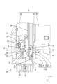
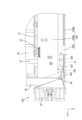
- FIG. 1 is a plan view of the electricity storage module according to the first embodiment, showing a state in which an electric wire housing section is open.
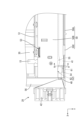
- FIG. 2 is a plan view of the power storage module according to the first embodiment, illustrating a state in which the electric wire receiving portion is closed.
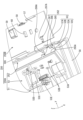
- FIG. 3 is a perspective view of the protector according to the first embodiment.
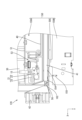
- FIG. 4 is an enlarged plan view of the wiring module according to the first embodiment, illustrating a state in which the electric wire receiving portion is opened.
- FIG. 5 is an enlarged plan view of the wiring module according to the first embodiment, illustrating a state in which the electric wire receiving portion is closed.
- FIG. 6 is a cross-sectional view taken along line AA of FIG. FIG.
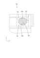
- FIG. 7 is an enlarged front view of the protector according to the first embodiment, showing the projected area of the internal space of the wire receiving portion.
- FIG. 8 is an enlarged plan view of the wiring module according to the second embodiment, illustrating a state in which the electric wire receiving portion is opened.
- FIG. 9 is an enlarged plan view of the wiring module according to the second embodiment, illustrating a state in which the electric wire receiving portion is closed.
- FIG. 10 is a cross-sectional view taken along line BB of FIG.
- FIG. 11 is a perspective view of a protector according to the second embodiment.
- FIG. 12 is an enlarged front view of the protector according to the second embodiment, showing the projected area of the internal space of the wire receiving portion.
- FIG. 13 is an enlarged plan view of the wiring module according to the third embodiment, illustrating a state in which the electric wire receiving portion is opened.
- FIG. 14 is an enlarged plan view of the wiring module according to the third embodiment, illustrating a state in which the electric wire receiving portion is closed.
- FIG. 15 is a cross-sectional view taken along the line CC of FIG.
- FIG. 16 is a perspective view of a protector according to the third embodiment.
- FIG. 17 is an enlarged front view of the protector according to the third embodiment, showing the projected area of the internal space of the wire receiving portion.
- a wiring module according to the present disclosure is a wiring module attached to a plurality of energy storage elements, the wiring module comprising: a plurality of electric wires; a plurality of circuit boards; and a protector that holds the plurality of circuit boards and the plurality of electric wires, wherein each of the electric wires is electrically connected to each of the circuit boards.
- the protector comprises an electric wire accommodating portion extending in a first direction and accommodating the plurality of electric wires, the electric wire accommodating portion comprising a peripheral wall arranged to surround the plurality of electric wires, and a first flex rib and a second flex rib extending from the peripheral wall inwardly of the electric wire accommodating portion, the first flex rib being arranged at a position offset in the first direction from the second flex rib, the first flex rib extending from the peripheral wall to one side in a second direction perpendicular to the first direction, and the second flex rib extending from the peripheral wall to the other side in the second direction.
- the first and second flex ribs can contact the multiple electric wires from opposite sides in the second direction, so that the multiple electric wires can be held in the electric wire accommodating section in a state where they are bent by the first and second flex ribs.
- the portions of the multiple electric wires bent by the first and second flex ribs are less likely to move in the first direction relative to the protector inside the electric wire accommodating section. Therefore, when the multiple electric wires are subjected to vibration or stress, stress can be prevented from occurring in the connection portion between the electric wires and the circuit board, and damage to the connection portion between the electric wires and the circuit board can be prevented.
- the pressing rib has a recess that is arc-shaped when viewed in the first direction.
- This configuration makes it easier to increase the contact area between the pressing rib and multiple electric wires.
- first bending rib and the second bending rib each have a recess that is arc-shaped when viewed in the first direction.
- the plurality of electric wires are bundled together to form a trunk section, and that the projected area of the internal space of the electric wire accommodating section as viewed in the first direction is set smaller than the cross-sectional area of the trunk section.
- This configuration makes it easier for the trunk portion to come into contact with the first and second bending ribs.
- the peripheral wall has a first wall portion from which the first flex rib extends and a second wall portion from which the second flex rib extends, the second wall portion faces the first wall portion in the second direction, and it is preferable that the distance between the first flex rib and the second flex rib in the first direction is set to be smaller than three times the distance between the first wall portion and the second wall portion in the second direction.
- This configuration can increase the frictional force between each of the first and second bending ribs and the multiple electric wires.
- the protector comprises a protector body and a lid body that is stacked on the protector body in a direction perpendicular to the first direction, and the wire accommodating section is composed of the protector body and the lid body.
- This configuration allows the wire housing to be easily constructed.
- facing in this specification refers to surfaces or components facing each other, and includes not only cases where they are completely facing each other, but also cases where they are partially facing each other.
- facing in this specification includes both cases where there is a component separate from the two parts between the two parts, and cases where there is nothing between the two parts.
- An energy storage module 10 including a wiring module 20 according to the present embodiment is mounted on a vehicle as a power source for driving the vehicle, such as an electric vehicle or a hybrid vehicle.
- the direction indicated by the arrow Z is the upward direction
- the direction indicated by the arrow X is the forward direction
- the direction indicated by the arrow Y is the leftward direction.
- the front-rear direction is an example of the first direction
- the left-right direction is an example of the second direction
- the up-down direction is an example of the third direction. Note that, for multiple identical members, only some of the members may be labeled with a reference symbol, and the reference symbols of the other members may be omitted.
- the energy storage module 10 comprises a number of energy storage elements 11 arranged in a row, and a wiring module 20 attached to the upper surfaces of the multiple energy storage elements 11.
- the wiring module 20 is attached to the right side of the multiple energy storage elements 11.
- a similar wiring module is also attached to the left side of the multiple energy storage elements 11.
- the energy storage element 11 has a flat rectangular parallelepiped shape with a storage element housed inside.
- the energy storage element 11 has two electrode terminals 12 located near the right end and the left end of the upper surface. One of the two electrode terminals 12 is a positive electrode, and the other is a negative electrode.
- the wiring module 20 includes a bus bar 30 connected to the electrode terminal 12 of the energy storage element 11, a circuit board 21 connected to the bus bar 30, an electric wire 40 connected to the circuit board 21, and a protector 50 that holds the bus bar 30, the circuit board 21, and the electric wire 40.
- the busbar 30 is made of a metal plate and has a rectangular shape in a plan view.
- the busbar 30 connects between adjacent electrode terminals 12 in the stacking direction (front-to-back direction) of the multiple storage elements 11.
- the wiring module 20 may also include an output busbar that is connected to the electrode terminals 12 (total positive or total negative) of the storage elements 11 that are arranged at the ends in the stacking direction.
- the busbar 30 and the electrode terminals 12 are connected by welding or the like.
- the busbar 30 is accommodated in a busbar accommodating portion 51 of the protector 50, which will be described later.
- the circuit board 21 is a flexible board, and is configured by forming a conductive path on the surface of a flexible insulating sheet by a printed wiring technology.
- the circuit board 21 includes a board body 22 and an extension portion 23 extending from the board body 22.
- the board body 22 is substantially rectangular in a plan view.
- the board body 22 is provided with an insertion hole 22B, and a protrusion 53B described later is inserted into the insertion hole 22B.
- the board body 22 is provided with an electric wire land 22A arranged at one end of the conductive path.
- the electric wire land 22A is connected to an electric wire 40 by soldering or the like.
- the extension portion 23 is in the form of a wire spring and is configured to be expandable and contractible.
- the provision of the extension portion 23 allows the end (tip) of the extension portion 23 opposite the substrate body 22 to be displaced a predetermined dimension relative to the substrate body 22.
- the tip of the extension portion 23 is provided with a connection land 23A that is disposed at the other end of the conductive path.
- the connection land 23A is electrically connected to the bus bar 30 via the metal piece 15.
- circuit board 21 may have multiple conductive paths, and the conductive paths may include part of a thermistor circuit for measuring the temperature of the storage element 11.
- the electric wires 40 connected to the circuit board 21 are collectively accommodated in an electric wire accommodating section 62 of the protector 50, which will be described later.
- the electric wires 40 are arranged in the electric wire accommodating section 62, extending in the front-rear direction.
- the electric wires 40 may include, in addition to a voltage detection wire electrically connected to the bus bar 30, a temperature detection wire connected to a thermistor that measures the temperature of the energy storage element 11, for example.
- the electric wires 40 are bundled together to form a trunk section 41.
- the trunk section 41 is formed by integrating the electric wires 40 with tape, a heat shrink tube, or the like.
- the trunk section 41 has a substantially cylindrical shape.
- the trunk section 41 has a predetermined rigidity and is bendable.
- the multiple electric wires 40 are connected to a connector 42 at the end opposite the circuit board 21.
- the connector 42 is adapted to be connected to an external ECU (Electronic Control Unit) or the like.
- the ECU is equipped with a microcomputer, elements, etc., and is of a well-known configuration with functions such as detecting the voltage, current, temperature, etc. of each storage element 11 and controlling the charging and discharging of each storage element 11.
- the protector body 50A is in the shape of a tray and includes a busbar accommodating portion 51 for accommodating the busbar 30, an accommodating recess 52 for accommodating the plurality of electric wires 40, and an intermediate wiring portion 53 disposed between the busbar accommodating portion 51 and the accommodating recess 52.
- the busbar accommodating portions 51 are frame-shaped and are arranged in a row in the front-rear direction.
- the circuit board 21 and the electric wires 40 connected to the circuit board 21 are arranged in the intermediate wiring section 53.
- the intermediate wiring section 53 has a mounting surface 53A on which the circuit board 21 is placed, a columnar protrusion 53B protruding upward from the mounting surface 53A, and a protrusion receiving section 53C recessed downward from the mounting surface 53A.
- the protrusion 53B is inserted into the insertion hole 22B of the circuit board 21. This positions the board body 22 in the intermediate wiring section 53.
- the intermediate wiring section 53 is provided with a partition wall 53D that rises upward from the mounting surface 53A.
- the partition wall 53D allows the positioning of the electric wire 40. It is preferable that the partition wall 53D is arranged around the protrusion receiving section 53C.
- the intermediate wiring section 53 has a lock receiving section 53E that engages with a lock section 58 of the lid body 50B, which will be described later.
- the lock receiving section 53E is located in a position in the intermediate wiring section 53 closer to the busbar accommodating section 51.
- the accommodating recess 52 includes a first bent rib 54 extending rightward from a first side wall 52B (an example of a first wall portion) and a second bent rib 55 extending leftward from a second side wall 52C (an example of a second wall portion).
- the first bent rib 54 and the second bent rib 55 extend inwardly of the accommodating recess 52 (wire accommodating portion 62) in the left-right direction.
- the lower end of the first bent rib 54 and the lower end of the second bent rib 55 are connected to the bottom wall 52A.
- the first bent rib 54 is located forward of the second bent rib 55.
- the first bent rib 54 and the second bent rib 55 are arranged near the end of the wire housing 62 (here, the front end of the wire housing 62) from which the multiple electric wires 40 are led out.
- An excess length arrangement section 56 is provided in a position forward of the end of the wire housing 62 in the protector body 50A.
- the excess length arrangement section 56 is capable of accommodating the excess of the electric wires 40 arranged between the trunk section 41 and the connector 42 and the connector 42.
- the first bent rib 54 contacts the trunk portion 41 from the left side
- the second bent rib 55 contacts the trunk portion 41 from the right side. This causes the trunk portion 41 to be bent in a roughly S-shape in plan view. Therefore, multiple electric wires 40 can be firmly held in the accommodation recess 52.
- the wiring module 20 of this embodiment is used in a vehicle, it is conceivable that vibrations will be applied to the electric wires 40. Furthermore, the electric wires 40 are connected to the connector 42, and it is assumed that tensile stress will be applied to the electric wires 40 when the connector 42 is connected to an external ECU or the like. As described above, in this embodiment, the main line portion 41 is bent by the first bending rib 54 and the second bending rib 55 in the electric wire accommodating portion 62. Therefore, even if vibrations or tensile stresses are applied to the electric wires 40, the vibrations and tensile stresses are unlikely to be transmitted to the connection portion between the electric wires 40 and the circuit board 21. Therefore, damage to the connection portion between the electric wires 40 and the circuit board 21 can be suppressed.
- the distance D1 between the first flex rib 54 and the second flex rib 55 in the front-rear direction is preferably set to be somewhat small.
- the distance D1 between the first flex rib 54 and the second flex rib 55 in the front-rear direction is preferably set to be smaller than three times the distance D2 between the first side wall 52B and the second side wall 52C in the left-right direction.
- the distance D1 between the first flex rib 54 and the second flex rib 55 in the front-rear direction may also be set to be smaller than three times the diameter D3 of the trunk portion 41.
- the trunk portion 41 is bent in an approximately S-shape in a narrow range in the front-rear direction, thereby increasing the restoring force of the trunk portion 41 to return from the bent state.
- the trunk portion 41 is brought into strong contact with the first flex rib 54 and the second flex rib 55, and the friction between the trunk portion 41 and the first flex rib 54 and the second flex rib 55 can be increased.
- the distance D4 (see FIG. 7) between the first flex rib 54 and the second flex rib 55 in the left-right direction is preferably set to be smaller than the diameter D3 (see FIG. 4) of the trunk portion 41.
- This dimension setting allows the trunk portion 41 to bend significantly by the first flex rib 54 and the second flex rib 55. This makes it easier to hold the trunk portion 41 more firmly in the wire housing portion 62.
- the cover 50B is configured to be able to close the accommodation recess 52 and the intermediate routing portion 53 of the protector body 50A from above. That is, the cover 50B may be stacked on the protector body 50A in a direction perpendicular to the first direction. For example, the cover 50B is stacked on the protector body 50A in a direction perpendicular to the first direction and intersecting with the second direction. As shown in Fig. 3, the cover 50B includes a plate-shaped portion 57, and a locking portion 58, a protruding portion 59, a convex portion 60, and a pressing rib 61 protruding from the plate-shaped portion 57. The locking portion 58 is engaged with the lock receiving portion 53E, so that the cover 50B can maintain a state in which the protector body 50A is closed.
- the protrusion 59 is, for example, block-shaped.
- the protrusion 59 is arranged to face the protrusion receiving portion 53C in the vertical direction, and the electric wire 40 is arranged between the protrusion 59 and the protrusion receiving portion 53C.
- the distance between the protrusion 59 and the protrusion receiving portion 53C is approximately the same as the diameter of the electric wire 40. This makes it easier for friction to occur between the electric wire 40 and the protrusion 59 or the protrusion receiving portion 53C when vibration or stress is applied to the electric wire 40. This makes it difficult for vibration or stress to be transmitted to the connection between the electric wire 40 and the circuit board 21, and makes it possible to suppress damage to the connection between the electric wire 40 and the circuit board 21.
- the protrusion 60 is, for example, block-shaped.
- the protrusion 60 is arranged opposite the mounting surface 53A, and the electric wire 40 is arranged between the protrusion 60 and the mounting surface 53A.
- the distance between the protrusion 60 and the mounting surface 53A is approximately the same as the diameter of the electric wire 40. This makes it easier for friction to occur between the electric wire 40 and the protrusion 60 or the mounting surface 53A when vibration or stress is applied to the electric wire 40. This makes it difficult for vibration or stress to be transmitted to the connection between the electric wire 40 and the circuit board 21, and makes it possible to suppress damage to the connection between the electric wire 40 and the circuit board 21.
- the portion of the plate-shaped portion 57 closer to the hinge portion 50C is a ceiling wall 57A that closes the housing recess 52.
- the cover 50B has a pressing rib 61 that extends from the ceiling wall 57A toward the inside of the housing recess 52 when the cover 50B closes the protector body 50A (see FIG. 6).
- the pressing rib 61 is disposed between the first bent rib 54 and the second bent rib 55 in the front-rear direction.
- the electric wire housing portion 62 of this embodiment is constituted by the housing recess 52 of the protector body 50A and the ceiling wall 57A and pressing rib 61 of the cover 50B.
- the peripheral wall 63 that is disposed to surround the trunk portion 41 in the electric wire housing portion 62 is constituted by the bottom wall 52A, the first side wall 52B, the second side wall 52C, and the ceiling wall 57A.
- the pressure rib 61 and the bottom wall 52A are configured to clamp the trunk portion 41 in the vertical direction.
- the pressure rib 61 can hold the trunk portion 41 more firmly in the wire accommodating portion 62, so that even if vibrations or stress are applied to the multiple electric wires 40, the transmission of vibrations or stress to the connection between the electric wires 40 and the circuit board 21 can be suppressed. This makes it possible to suppress damage to the connection between the electric wires 40 and the circuit board 21.
- the pressing rib 61 has a recess 61A recessed from the protruding end toward the ceiling wall 57A.
- the recess 61A is formed in an arc shape when viewed from the front-rear direction.
- the projected area 64 may be 70% or less of the cross-sectional area 41A of the trunk portion 41. According to this configuration, the continuous space is reduced, so that the trunk portion 41 is more likely to come into contact with the first bent rib 54, the second bent rib 55, and the pressing rib 61. Therefore, the trunk portion 41 can be held more firmly in the electric wire accommodating section 62.
- the wiring module 20 is a wiring module 20 attached to a plurality of energy storage elements 11, and includes a plurality of electric wires 40, a plurality of circuit boards 21, and a protector 50 that holds the plurality of circuit boards 21 and the plurality of electric wires 40.
- Each electric wire 40 is electrically connected to each circuit board 21.
- the protector 50 includes an electric wire accommodating portion 62 that extends in a first direction (front-rear direction) and accommodates the plurality of electric wires 40. No.
- the second flex rib 55 extending from the peripheral wall 63 to the other side in the second direction.
- the first flex rib 54 and the second flex rib 55 can contact the multiple electric wires 40 from opposite sides in the second direction, so that the multiple electric wires 40 can be held in the electric wire accommodating section 62 in a state where they are bent by the first flex rib 54 and the second flex rib 55. Therefore, the portions of the multiple electric wires 40 bent by the first flex rib 54 and the second flex rib 55 are less likely to move in the first direction relative to the protector 50 inside the electric wire accommodating section 62. Therefore, when vibration or stress is applied to the multiple electric wires 40, stress can be suppressed from occurring in the connection portion between the electric wires 40 and the circuit board 21, and damage to the connection portion between the electric wires 40 and the circuit board 21 can be suppressed.
- the electric wire accommodating section 62 further includes a pressing rib 61 extending from the peripheral wall 63 inwardly of the electric wire accommodating section 62, the pressing rib 61 being disposed between the first bent rib 54 and the second bent rib 55 in the first direction, and the multiple electric wires 40 are clamped by the peripheral wall 63 and the pressing rib 61 in a third direction (up-down direction) that is perpendicular to the first direction and intersects with the second direction.
- the multiple electric wires 40 can be clamped between the peripheral wall 63 and the pressure rib 61, making it easier for the multiple electric wires 40 to be more firmly held by the electric wire accommodating portion 62 around the first bent rib 54 and the second bent rib 55.
- the pressing rib 61 has a recess 61A that is arc-shaped when viewed in the first direction.
- This configuration makes it easier to increase the contact area between the pressing rib 61 and the multiple electric wires 40. Therefore, the frictional force between the pressing rib 61 and the electric wires 40 can be increased, and movement of the electric wires 40 in the first direction relative to the electric wire accommodating portion 62 in the vicinity of the pressing rib 61 can be further suppressed.
- This configuration makes it easier for the trunk portion 41 to come into contact with the first bend rib 54 and the second bend rib 55. Therefore, the portions of the multiple electric wires 40 that are bent by the first bend rib 54 and the second bend rib 55 are even less likely to move in the first direction relative to the protector 50 inside the electric wire accommodating portion 62. This makes it possible to further suppress damage to the connection between the electric wires 40 and the circuit board 21.
- the peripheral wall 63 has a first wall portion (first side wall 52B) from which the first flex rib 54 extends and a second wall portion (second side wall 52C) from which the second flex rib 55 extends, the second wall portion faces the first wall portion in the second direction, and the distance D1 between the first flex rib 54 and the second flex rib 55 in the first direction is set to be smaller than three times the distance D2 between the first wall portion and the second wall portion in the second direction.
- This configuration can increase the frictional force between each of the first and second bending ribs 54, 55 and the multiple electric wires 40. Therefore, the portions of the multiple electric wires 40 bent by the first and second bending ribs 54, 55 become even more difficult to move in the first direction relative to the protector 50, so damage to the connection between the electric wires 40 and the circuit board 21 can be further suppressed.
- the protector 50 includes a protector body 50A and a cover body 50B that is stacked on the protector body 50A in a direction perpendicular to the first direction, and the wire accommodating section 62 is composed of the protector body 50A and the cover body 50B.
- This configuration allows the wire housing 62 to be easily constructed.
- the wiring module 120 according to the second embodiment is configured substantially similarly to the first embodiment, except for the configurations of the first bending rib 154 and the second bending rib 155.
- the front-rear direction is an example of the first direction
- the up-down direction is an example of the second direction.
- the same members as those in the first embodiment are given the same reference numerals, and detailed description of the same configurations and effects as those in the first embodiment will be omitted.
- the wiring module 120 of this embodiment includes a protector 150, which includes a protector body 150A and a cover body 150B.
- the protector 150 includes an electric wire accommodating section 162 that accommodates a plurality of electric wires 40.
- the electric wire accommodating section 162 is composed of the accommodating recess 152 of the protector body 150A and the ceiling wall 57A and second bent rib 155 of the cover body 150B.
- the accommodation recess 152 includes two first bent ribs 154 extending upward from the bottom wall 52A. A left end of the first bent rib 154 is connected to the first side wall 52B, and a right end of the first bent rib 154 is connected to the second side wall 52C. The two first bent ribs 154 are spaced apart in the front-rear direction.
- the first bent rib 154 has a recess 154A recessed from the protruding end toward the bottom wall 52A.
- the recess 154A is formed in an arc shape when viewed from the front-rear direction.
- the cover 150B includes a second bent rib 155 extending from the ceiling wall 57A.
- the second bent rib 155 extends toward the bottom wall 52A (downward).
- the second bent rib 155 is disposed between the two first bent ribs 154 in the front-rear direction.
- the second bent rib 155 has a recess 155A recessed from the protruding end toward the ceiling wall 57A.
- the recess 155A is formed in an arc shape when viewed from the front-rear direction.
- the first bent rib 154 contacts the main wire portion 41 from below, and the second bent rib 155 contacts the main wire portion 41 from above.
- the internal space of the electric wire accommodating section 162 includes a continuous space extending in the front-rear direction without being blocked by the first bent rib 154 and the second bent rib 155.
- the space (hatched area in the figure) that is elliptical when viewed from the front and arranged inside the recesses 154A and 155A is an entry space into which the trunk portion 41 can enter.
- the area of this entry space when viewed from the front-rear direction is defined as a projected area 164.
- the projected area 164 is set to be smaller than the cross-sectional area 41A of the trunk portion 41. According to this configuration, the entry space is reduced, so that the trunk portion 41 is more likely to come into contact with the first bent rib 154 and the second bent rib 155. Therefore, the trunk portion 41 can be held more firmly in the electric wire accommodating section 162.
- the first curved rib 154 and the second curved rib 155 each have recesses 154A, 155A that are arc-shaped when viewed in the first direction.
- This configuration makes it easier to increase the contact area between the first and second bend ribs 154, 155 and the multiple electric wires 40. This increases the frictional force between the first and second bend ribs 154, 155 and the electric wires 40, and further prevents the electric wires 40 from moving in the first direction relative to the electric wire accommodating portion 162 in the vicinity of the first and second bend ribs 154, 155.
- a third embodiment of the present disclosure will be described with reference to Figs. 13 to 17.
- a wiring module 220 according to the third embodiment is configured substantially similarly to the first embodiment, except for the configurations of a front rib 265, a rear rib 266, and an intermediate rib 267.
- the front-rear direction is an example of the first direction.
- the same members as those in the first embodiment are denoted by the same reference numerals, and detailed description of the same configurations, functions, and effects as those in the first embodiment will be omitted.
- the wiring module 220 of this embodiment includes a protector 250, which includes a protector body 250A and a cover body 250B.
- the protector 250 includes an electric wire accommodating section 262 that accommodates a plurality of electric wires 40.
- the electric wire accommodating section 262 is composed of the accommodating recess 252 of the protector body 250A and the ceiling wall 57A and intermediate rib 267 of the cover body 250B.
- the accommodating recess 252 includes a front rib 265 and a rear rib 266 located rearward of the front rib 265.
- the front rib 265 extends upward from the bottom wall 52A and extends rightward from the first side wall 52B.
- a right end of the front rib 265 is connected to the second side wall 52C.
- the rear rib 266 extends upward from the bottom wall 52A and extends leftward from the second side wall 52C.
- a left end of the rear rib 266 is connected to the first side wall 52B.
- a recess 265A is formed on the right side of the front rib 265, recessed from the protruding end toward the bottom wall 52A.
- the recess 265A is formed in an arc shape when viewed from the front-rear direction.
- a recess 266A is formed on the left side of the rear rib 266, recessed from the protruding end toward the bottom wall 52A.
- the recess 266A is formed in an arc shape when viewed from the front-rear direction.
- the cover 250B includes an intermediate rib 267 extending from the top wall 57A. When the cover 250B closes the protector body 250A, the intermediate rib 267 extends toward the bottom wall 52A (downward). The intermediate rib 267 is disposed between the front rib 265 and the rear rib 266 in the front-rear direction.
- the intermediate rib 267 has a recess 267A recessed from the protruding end toward the ceiling wall 57A.
- the recess 267A is formed in an arc shape when viewed from the front-rear direction.
- the front rib 265 contacts the main line 41 from the left side, and the rear rib 266 contacts the main line 41 from the right side.
- the intermediate rib 267 is disposed between the front rib 265 and the rear rib 266 in the front-rear direction, and holds the main line 41 in the up-down direction together with the bottom wall 52A, so the intermediate rib 267 can be considered an example of a pressing rib, and the up-down direction an example of a third direction.
- the front rib 265 and the rear rib 266 contact the trunk portion 41 from below, and the intermediate rib 267 contacts the trunk portion 41 from above. This causes the trunk portion 41 to bend in a roughly S-shape when viewed from the left-right direction.
- the front rib 265 and the rear rib 266 can be considered as an example of a first bent rib, the intermediate rib 267 as an example of a second bent rib, and the up-down direction as an example of a second direction.
- the main wire portion 41 bends in plan and side views while contacting the front rib 265, the rear rib 266, and the intermediate rib 267, so that the multiple electric wires 40 can be firmly held in the electric wire storage portion 262.
- the internal space of the electric wire accommodating portion 262 includes a continuous space (shaded portion in the figure) extending in the front-rear direction without being interrupted by the front rib 265, the rear rib 266, and the intermediate rib 267.
- the area of this continuous space when viewed from the front-rear direction is defined as a projected area 264.
- the projected area 264 is set to be smaller than the cross-sectional area 41A of the trunk portion 41.
- the peripheral wall 63 has a bottom wall 52A, a first side wall 52B, a second side wall 52C, and a ceiling wall 57A, and is in the shape of a rectangular tube, but the peripheral wall may be, for example, cylindrical. Also, in the above embodiments 1 to 3, the peripheral wall 63 is arranged to cover the entire outer periphery of the multiple electric wires 40, but it is sufficient that the peripheral wall covers at least a portion of the outer periphery of the multiple electric wires.
- the peripheral wall may not have a ceiling wall, and may be composed of a bottom wall, a first side wall, and a second side wall.
- the multiple electric wires 40 are bundled together to form the trunk section 41, but the multiple electric wires do not have to form the trunk section.
- the wire housing 62, 162, 262 is composed of the protector body 50A, 150A, 250A and the cover body 50B, 150B, 250B, respectively, but the wire housing may be composed of a single member.
- the circuit board 21 is a flexible board, but the circuit board may be a rigid board.
Landscapes
- Details Of Indoor Wiring (AREA)
- Fixed Capacitors And Capacitor Manufacturing Machines (AREA)
- Battery Mounting, Suspending (AREA)
- Connection Of Batteries Or Terminals (AREA)
Abstract
配線モジュール20は、複数の蓄電素子に取り付けられる配線モジュール20であって、複数の電線40と、複数の回路基板21と、複数の回路基板21及び複数の電線40を保持するプロテクタ50と、を備え、各電線40は各回路基板21と電気的に接続され、プロテクタ50は、第1方向に延び複数の電線40を収容する電線収容部62を備え、電線収容部62は、複数の電線40を包囲するように配される周壁63と、周壁63から電線収容部62の内方に延びる第1屈曲リブ54及び第2屈曲リブ55と、を備え、第1屈曲リブ54は、第2屈曲リブ55と第1方向にずれた位置に配され、第1屈曲リブ54は、周壁63から第1方向に直交する第2方向における一方側に延び、第2屈曲リブ55は、周壁63から第2方向における他方側に延びている。
Description
本開示は、配線モジュールに関する。
電気自動車やハイブリッド自動車等に用いられる高圧のバッテリーパックは、通常、多数のバッテリが積層され、配線モジュールによって直列あるいは並列に電気接続されている。このような配線モジュールとして、従来、特開2019-23996号公報(下記特許文献1)に記載のバッテリ接続モジュールが知られている。特許文献1に記載のバッテリ接続モジュールは、バスバーと、バスバーに接続されるフレキシブル回路基板と、を備えて構成されている。フレキシブル回路基板はその端部にコネクタを含んでいる。
上記の構成とは異なり、配線モジュールは、バスバーと、バスバーに接続される回路基板と、回路基板に接続される電線と、を備えてもよい。また、電線の端部にはコネクタが接続されていてもよい。回路基板と電線との接続は、例えば、半田付け等により行うことが考えられる。こうした配置モジュールにおいて、回路基板と電線との接続部は、例えば電線に振動あるいは応力が加わった場合や、コネクタの嵌合操作時に電線が引っ張られたた場合等に、損傷することがありうる。
本開示の配線モジュールは、複数の蓄電素子に取り付けられる配線モジュールであって、複数の電線と、複数の回路基板と、前記複数の回路基板及び前記複数の電線を保持するプロテクタと、を備え、各前記電線は各前記回路基板と電気的に接続され、前記プロテクタは、第1方向に延び前記複数の電線を収容する電線収容部を備え、前記電線収容部は、前記複数の電線を包囲するように配される周壁と、前記周壁から前記電線収容部の内方に延びる第1屈曲リブ及び第2屈曲リブと、を備え、前記第1屈曲リブは、前記第2屈曲リブと前記第1方向にずれた位置に配され、前記第1屈曲リブは、前記周壁から前記第1方向に直交する第2方向における一方側に延び、前記第2屈曲リブは、前記周壁から前記第2方向における他方側に延びている、配線モジュールである。
本開示によれば、回路基板と電線との接続部の損傷を抑制可能な配線モジュールを提供することができる。
[本開示の実施形態の説明]
最初に本開示の実施態様を列挙して説明する。
[1]本開示の配線モジュールは、複数の蓄電素子に取り付けられる配線モジュールであって、複数の電線と、複数の回路基板と、前記複数の回路基板及び前記複数の電線を保持するプロテクタと、を備え、各前記電線は各前記回路基板と電気的に接続され、前記プロテクタは、第1方向に延び前記複数の電線を収容する電線収容部を備え、前記電線収容部は、前記複数の電線を包囲するように配される周壁と、前記周壁から前記電線収容部の内方に延びる第1屈曲リブ及び第2屈曲リブと、を備え、前記第1屈曲リブは、前記第2屈曲リブと前記第1方向にずれた位置に配され、前記第1屈曲リブは、前記周壁から前記第1方向に直交する第2方向における一方側に延び、前記第2屈曲リブは、前記周壁から前記第2方向における他方側に延びている。
最初に本開示の実施態様を列挙して説明する。
[1]本開示の配線モジュールは、複数の蓄電素子に取り付けられる配線モジュールであって、複数の電線と、複数の回路基板と、前記複数の回路基板及び前記複数の電線を保持するプロテクタと、を備え、各前記電線は各前記回路基板と電気的に接続され、前記プロテクタは、第1方向に延び前記複数の電線を収容する電線収容部を備え、前記電線収容部は、前記複数の電線を包囲するように配される周壁と、前記周壁から前記電線収容部の内方に延びる第1屈曲リブ及び第2屈曲リブと、を備え、前記第1屈曲リブは、前記第2屈曲リブと前記第1方向にずれた位置に配され、前記第1屈曲リブは、前記周壁から前記第1方向に直交する第2方向における一方側に延び、前記第2屈曲リブは、前記周壁から前記第2方向における他方側に延びている。
このような構成によると、第1屈曲リブと第2屈曲リブとは互いに第2方向における反対側から複数の電線に接触することができるから、複数の電線を第1屈曲リブと第2屈曲リブとによって屈曲させた状態で電線収容部に保持することができる。このため、複数の電線において第1屈曲リブと第2屈曲リブとによって屈曲された部分は、電線収容部の内部でプロテクタに対して第1方向に移動し難くなる。よって、複数の電線に振動や応力がかかった場合に、電線と回路基板との接続部分に応力が生じることを抑制できるため、電線と回路基板との接続部の損傷を抑制することができる。
[2]上記[1]において、前記電線収容部は、前記周壁から前記電線収容部の内方に延びる押圧リブをさらに備え、前記押圧リブは、前記第1方向について前記第1屈曲リブと前記第2屈曲リブとの間に配され、前記複数の電線は、前記周壁と前記押圧リブとによって、前記第1方向に直交するとともに前記第2方向と交差する第3方向に挟持されるようになっていることが好ましい。
このような構成によると、周壁と押圧リブとにより複数の電線を挟持することができるから、第1屈曲リブ及び第2屈曲リブの周辺で複数の電線を電線収容部により、一層強固に保持しやすくなる。
[3]上記[2]において、前記押圧リブは、前記第1方向視において円弧状をなす凹部を有することが好ましい。
このような構成によると、押圧リブと複数の電線との接触面積を増大させやすくなる。
[4]上記[1]から[3]のいずれか1つにおいて、前記第1屈曲リブ及び前記第2屈曲リブは、それぞれ前記第1方向視において円弧状をなす凹部を有することが好ましい。
このような構成によると、第1屈曲リブ及び第2屈曲リブと複数の電線との接触面積を増大させやすくなる。
[5]上記[1]から[4]のいずれか1つにおいて、前記複数の電線は束ねられて幹線部を構成しており、前記電線収容部の内部空間の前記第1方向視における投影面積は、前記幹線部の断面積よりも小さく設定されていることが好ましい。
このような構成によると、幹線部が第1屈曲リブ及び第2屈曲リブと接触しやすくなる。
[6]上記[1]から[5]のいずれか1つにおいて、前記周壁は、前記第1屈曲リブが延出される第1壁部と、前記第2屈曲リブが延出される第2壁部と、を備え、前記第2壁部は、前記第2方向について前記第1壁部と対向し、前記第1方向における前記第1屈曲リブと前記第2屈曲リブとの間隔は、前記第2方向における前記第1壁部と前記第2壁部との間隔の3倍よりも小さく設定されていることが好ましい。
このような構成によると、第1屈曲リブ及び第2屈曲リブのそれぞれと複数の電線との間の摩擦力を高めることができる。
[7]上記[1]から[6]のいずれか1つにおいて、前記プロテクタは、プロテクタ本体と、前記プロテクタ本体に対して前記第1方向と直交する方向に重ねられる蓋体と、を備え、前記電線収容部は、前記プロテクタ本体と前記蓋体とから構成されていることが好ましい。
このような構成によると、電線収容部を簡便に構成することができる。
[本開示の実施形態の詳細]
以下に、本開示の実施形態について説明する。本開示はこれらの例示に限定されるものではなく、特許請求の範囲によって示され、特許請求の範囲と均等の意味および範囲内での全ての変更が含まれることが意図される。各図面では、説明の便宜上、構成の一部を誇張または簡略化して示す場合がある。また、各部分の寸法比率については各図面で異なる場合がある。本明細書における「直交」は、厳密に直交の場合のみでなく、本実施形態における作用ならびに効果を奏する範囲内で概ね直交の場合も含まれる。
以下に、本開示の実施形態について説明する。本開示はこれらの例示に限定されるものではなく、特許請求の範囲によって示され、特許請求の範囲と均等の意味および範囲内での全ての変更が含まれることが意図される。各図面では、説明の便宜上、構成の一部を誇張または簡略化して示す場合がある。また、各部分の寸法比率については各図面で異なる場合がある。本明細書における「直交」は、厳密に直交の場合のみでなく、本実施形態における作用ならびに効果を奏する範囲内で概ね直交の場合も含まれる。
また、本明細書における「対向」とは、面同士又は部材同士が互いに正面の位置にあることを指し、互いが完全に正面の位置にある場合だけでなく、互いが部分的に正面の位置にある場合を含む。また、本明細書における「対向」とは、2つの部分の間に、2つの部分とは別の部材が介在している場合と、2つの部分の間に何も介在していない場合の両方を含む。
<実施形態1>
本開示の実施形態1について、図1から図7を参照しつつ説明する。本実施形態の配線モジュール20を備えた蓄電モジュール10は、例えば、電気自動車またはハイブリッド自動車などの車両を駆動するための電源として車両に搭載されるものである。以下の説明においては、矢線Zの示す方向を上方、矢線Xの示す方向を前方、矢線Yの示す方向を左方として説明する。本実施形態では、前後方向は第1方向の一例、左右方向は第2方向の一例、上下方向は第3方向の一例である。なお、複数の同一部材については、一部の部材にのみ符号を付し、他の部材の符号を省略する場合がある。
本開示の実施形態1について、図1から図7を参照しつつ説明する。本実施形態の配線モジュール20を備えた蓄電モジュール10は、例えば、電気自動車またはハイブリッド自動車などの車両を駆動するための電源として車両に搭載されるものである。以下の説明においては、矢線Zの示す方向を上方、矢線Xの示す方向を前方、矢線Yの示す方向を左方として説明する。本実施形態では、前後方向は第1方向の一例、左右方向は第2方向の一例、上下方向は第3方向の一例である。なお、複数の同一部材については、一部の部材にのみ符号を付し、他の部材の符号を省略する場合がある。
蓄電モジュール10は、図1及び図2に示すように、一列に並べられた複数の蓄電素子11と、複数の蓄電素子11の上面に装着される配線モジュール20と、を備える。配線モジュール20は、複数の蓄電素子11の右側部分に取り付けられている。なお、図示しないものの、複数の蓄電素子11の左側部分にも同様の配線モジュールが取り付けられる。蓄電素子11は、内部に蓄電要素が収容された扁平な直方体状をなしている。蓄電素子11は、上面の右端部寄りの位置と左端部寄りの位置に2つの電極端子12を有する。2つの電極端子12のうち一方は正極であり、他方は負極である。
(配線モジュール20)
図1に示すように、配線モジュール20は、蓄電素子11の電極端子12に接続されるバスバー30と、バスバー30に接続される回路基板21と、回路基板21に接続される電線40と、バスバー30、回路基板21、及び電線40を保持するプロテクタ50と、を備える。
図1に示すように、配線モジュール20は、蓄電素子11の電極端子12に接続されるバスバー30と、バスバー30に接続される回路基板21と、回路基板21に接続される電線40と、バスバー30、回路基板21、及び電線40を保持するプロテクタ50と、を備える。
バスバー30は金属板材から構成され、平面視方形状をなしている。バスバー30は複数の蓄電素子11の積層方向(前後方向)に隣接する電極端子12間を接続している。また、図示しないが、配線モジュール20は、積層方向の端部に配される蓄電素子11の電極端子12(総正極または総負極)に接続される出力バスバーを備えてもよい。バスバー30と電極端子12との接続は、溶接等により行われる。バスバー30は後述するプロテクタ50のバスバー収容部51に収容されている。
(回路基板21)
回路基板21は、本実施形態では、フレキシブル基板とされており、可撓性を有する絶縁性のシートの表面にプリント配線技術により導電路が形成されて構成されている。図4に示すように、回路基板21は、基板本体22と、基板本体22から延出される延出部23と、を備える。基板本体22は、平面視略方形状をなしている。基板本体22には挿通孔22Bが設けられており、この挿通孔22Bに後述する突起53Bが挿通されるようになっている。基板本体22には、導電路の一端に配される電線ランド22Aが設けられている。電線ランド22Aは、半田付け等により電線40に接続される。
回路基板21は、本実施形態では、フレキシブル基板とされており、可撓性を有する絶縁性のシートの表面にプリント配線技術により導電路が形成されて構成されている。図4に示すように、回路基板21は、基板本体22と、基板本体22から延出される延出部23と、を備える。基板本体22は、平面視略方形状をなしている。基板本体22には挿通孔22Bが設けられており、この挿通孔22Bに後述する突起53Bが挿通されるようになっている。基板本体22には、導電路の一端に配される電線ランド22Aが設けられている。電線ランド22Aは、半田付け等により電線40に接続される。
延出部23は線ばね状をなし、伸縮可能に構成されている。延出部23が設けられることにより、延出部23の基板本体22と反対側の端部(先端部)が基板本体22に対して所定寸法変位することが許容されるようになっている。延出部23の先端部には、導電路の他端に配される接続ランド23Aが設けられている。接続ランド23Aは、金属小片15を介してバスバー30と電気的に接続される。
図示しないものの、回路基板21の導電路にはヒューズ等が設けられていてもよい。また、回路基板21は複数の導電路を備え、導電路は蓄電素子11の温度を測定するためのサーミスタ回路の一部を含んでもよい。
(電線40、幹線部41)
回路基板21に接続された電線40は、後述するプロテクタ50の電線収容部62へとまとめて収容される。複数の電線40は電線収容部62内において前後方向に延びて配されている。なお、複数の電線40は、バスバー30に電気的に接続される電圧検知線の他に、例えば蓄電素子11の温度を測定するサーミスタに接続された温度検知線を含んでもよい。複数の電線40は束ねられて幹線部41を構成している。詳細には、幹線部41は、複数の電線40をテープや熱収縮チューブ等により一体化することにより構成されている。幹線部41は略円柱形状をなしている。幹線部41は所定の剛性を有し、屈曲可能となっている。
回路基板21に接続された電線40は、後述するプロテクタ50の電線収容部62へとまとめて収容される。複数の電線40は電線収容部62内において前後方向に延びて配されている。なお、複数の電線40は、バスバー30に電気的に接続される電圧検知線の他に、例えば蓄電素子11の温度を測定するサーミスタに接続された温度検知線を含んでもよい。複数の電線40は束ねられて幹線部41を構成している。詳細には、幹線部41は、複数の電線40をテープや熱収縮チューブ等により一体化することにより構成されている。幹線部41は略円柱形状をなしている。幹線部41は所定の剛性を有し、屈曲可能となっている。
複数の電線40は、回路基板21と反対側の端部においてコネクタ42に接続されている。コネクタ42は、外部のECU(Electronic Control Unit)等に接続されるようになっている。ECUは、マイクロコンピュータ、素子等が搭載されたものであって、各蓄電素子11の電圧、電流、温度等の検知や、各蓄電素子11の充放電制御コントロール等を行うための機能を備えた周知の構成のものである。
(プロテクタ50)
プロテクタ50は絶縁性の合成樹脂から構成されている。図3から図5に示すように、プロテクタ50は、プロテクタ本体50Aと、プロテクタ本体50Aを上方から覆う蓋体50Bと、を備える。蓋体50Bはヒンジ部50Cを介してプロテクタ本体50Aと一体的に形成されている。ヒンジ部50Cは弾性変形可能に構成されている。図5に示すように、ヒンジ部50Cを弾性変形させることにより、蓋体50Bをプロテクタ本体50Aの上方に重ねて組み付けることができる。
プロテクタ50は絶縁性の合成樹脂から構成されている。図3から図5に示すように、プロテクタ50は、プロテクタ本体50Aと、プロテクタ本体50Aを上方から覆う蓋体50Bと、を備える。蓋体50Bはヒンジ部50Cを介してプロテクタ本体50Aと一体的に形成されている。ヒンジ部50Cは弾性変形可能に構成されている。図5に示すように、ヒンジ部50Cを弾性変形させることにより、蓋体50Bをプロテクタ本体50Aの上方に重ねて組み付けることができる。
(プロテクタ本体50A)
図3に示すように、プロテクタ本体50Aはトレイ状をなしている。プロテクタ本体50Aは、バスバー30が収容されるバスバー収容部51と、複数の電線40が収容される収容凹部52と、バスバー収容部51と収容凹部52との間に配される中間配索部53と、を備える。バスバー収容部51は、枠状をなして、前後方向に並んで配置されている。
図3に示すように、プロテクタ本体50Aはトレイ状をなしている。プロテクタ本体50Aは、バスバー30が収容されるバスバー収容部51と、複数の電線40が収容される収容凹部52と、バスバー収容部51と収容凹部52との間に配される中間配索部53と、を備える。バスバー収容部51は、枠状をなして、前後方向に並んで配置されている。
図4に示すように、中間配索部53には、回路基板21と、回路基板21に接続された電線40と、が配置されている。図3に示すように、中間配索部53は、回路基板21が載置される載置面53Aと、載置面53Aから上方に突出する柱状の突起53Bと、載置面53Aから下方に凹む突出部受け部53Cと、を有する。突起53Bは回路基板21の挿通孔22Bに挿通される。これにより、基板本体22は中間配索部53において位置決めされる。
中間配索部53には、載置面53Aから上方に立ち上がる仕切壁53Dが設けられている。仕切壁53Dにより電線40の位置決めを行うことができる。仕切壁53Dは突出部受け部53Cの周囲に配されることが好ましい。
中間配索部53は、後述する蓋体50Bのロック部58と係止するロック受け部53Eを有する。ロック受け部53Eは、中間配索部53におけるバスバー収容部51寄りの位置に配されている。
収容凹部52は溝状をなし、前後方向に延びている。収容凹部52は、後述するように蓋体50Bとともに電線収容部62を構成する。収容凹部52は底壁52Aと、底壁52Aの左端縁から上方に立ち上がる第1側壁52Bと、底壁52Aの右端縁から上方に立ち上がる第2側壁52Cと、を備える。第1側壁52Bはヒンジ部50Cを介して蓋体50Bと接続されている。第2側壁52Cには、図示しない切り欠き部が形成されている。この切り欠き部を通じて中間配索部53から収容凹部52へと電線40が受け入れられるようになっている。
(第1屈曲リブ54、第2屈曲リブ55)
収容凹部52は、第1側壁52B(第1壁部の一例)から右方に延びる第1屈曲リブ54と、第2側壁52C(第2壁部の一例)から左方に延びる第2屈曲リブ55と、を備える。第1屈曲リブ54及び第2屈曲リブ55は、左右方向について収容凹部52(電線収容部62)の内方に向かって延びている。第1屈曲リブ54の下端部及び第2屈曲リブ55の下端部は、底壁52Aに接続されている。第1屈曲リブ54は第2屈曲リブ55より前方に位置している。
収容凹部52は、第1側壁52B(第1壁部の一例)から右方に延びる第1屈曲リブ54と、第2側壁52C(第2壁部の一例)から左方に延びる第2屈曲リブ55と、を備える。第1屈曲リブ54及び第2屈曲リブ55は、左右方向について収容凹部52(電線収容部62)の内方に向かって延びている。第1屈曲リブ54の下端部及び第2屈曲リブ55の下端部は、底壁52Aに接続されている。第1屈曲リブ54は第2屈曲リブ55より前方に位置している。
第1屈曲リブ54及び第2屈曲リブ55は、複数の電線40が導出される電線収容部62の終端部(ここでは電線収容部62の前端部)の近傍に配されている。プロテクタ本体50Aにおける電線収容部62の終端部よりも前側の位置には、余長部配設部56が設けられている。余長部配設部56は、幹線部41とコネクタ42との間に配される電線40の余長部やコネクタ42を配設可能とされている。
図4に示すように、収容凹部52内に幹線部41が収容されると、第1屈曲リブ54は左側から幹線部41に接触し、第2屈曲リブ55は右側から幹線部41に接触する。これにより、幹線部41は平面視において略S字状に屈曲した状態となる。したがって、収容凹部52において複数の電線40を強固に保持することができる。
本実施形態の配線モジュール20は車両に用いられるため、電線40に振動が加わることが考えられる。また、複数の電線40はコネクタ42に接続されており、このコネクタ42を外部のECU等に接続する際に、複数の電線40に引っ張り応力が加わることが想定される。上記したように、本実施形態では、電線収容部62において幹線部41が第1屈曲リブ54及び第2屈曲リブ55により屈曲された状態となっている。このため、複数の電線40に振動や引っ張り応力が加わった場合でも、電線40と回路基板21との接続部に振動や引っ張り応力が伝わりにくくなっている。したがって、電線40と回路基板21との接続部の損傷を抑制することができる。
前後方向における第1屈曲リブ54と第2屈曲リブ55との間隔D1は、ある程度小さく設定されることが好ましい。例えば、前後方向における第1屈曲リブ54と第2屈曲リブ55との間隔D1は、左右方向における第1側壁52Bと第2側壁52Cとの間隔D2の3倍よりも小さく設定されていることが好ましい。また、前後方向における第1屈曲リブ54と第2屈曲リブ55との間隔D1は、幹線部41の径D3の3倍よりも小さく設定されていてもよい。このような寸法設定によれば、幹線部41を前後方向について狭い範囲で略S字状に屈曲させることで、幹線部41が屈曲状態から復帰しようとする復元力を高めることができる。この結果、幹線部41と第1屈曲リブ54及び第2屈曲リブ55とを強く接触させ、幹線部41と第1屈曲リブ54及び第2屈曲リブ55との間の摩擦を大きくすることができる。
左右方向における第1屈曲リブ54と第2屈曲リブ55との間隔D4(図7参照)は、幹線部41の径D3(図4参照)よりも小さく設定されていることが好ましい。このような寸法設定によれば、第1屈曲リブ54と第2屈曲リブ55とにより幹線部41を大きく屈曲させることができる。よって、電線収容部62にさらに強固に幹線部41を保持しやすくなる。
(蓋体50B)
図3から図5に示すように、蓋体50Bはプロテクタ本体50Aの収容凹部52及び中間配索部53を上方から閉塞可能に構成されている。すなわち、蓋体50Bは、プロテクタ本体50Aに対して第1方向と直交する方向に重ねられていてもよい。例えば、蓋体50Bは、プロテクタ本体50Aに対して第1方向と直交し且つ第2方向と交差する方向に重ねられている。図3に示すように、蓋体50Bは、板状部57と、板状部57から突出するロック部58、突出部59、凸部60、及び押圧リブ61と、を備える。ロック部58がロック受け部53Eと係止することにより、蓋体50Bがプロテクタ本体50Aを閉塞した状態を維持可能とされている。
図3から図5に示すように、蓋体50Bはプロテクタ本体50Aの収容凹部52及び中間配索部53を上方から閉塞可能に構成されている。すなわち、蓋体50Bは、プロテクタ本体50Aに対して第1方向と直交する方向に重ねられていてもよい。例えば、蓋体50Bは、プロテクタ本体50Aに対して第1方向と直交し且つ第2方向と交差する方向に重ねられている。図3に示すように、蓋体50Bは、板状部57と、板状部57から突出するロック部58、突出部59、凸部60、及び押圧リブ61と、を備える。ロック部58がロック受け部53Eと係止することにより、蓋体50Bがプロテクタ本体50Aを閉塞した状態を維持可能とされている。
突出部59は、例えばブロック状をなしている。蓋体50Bがプロテクタ本体50Aを閉塞した状態で、突出部59は突出部受け部53Cと上下方向に対向して配され、突出部59と突出部受け部53Cとの間には電線40が配されるようになっている。突出部59と突出部受け部53Cとの間隔は、電線40の径と同程度となっている。これにより、電線40に振動や応力が加わった場合に、電線40と突出部59または突出部受け部53Cとの間に摩擦が生じやすくなる。よって、振動や応力が電線40と回路基板21との接続部に伝わりにくくなり、電線40と回路基板21との接続部の損傷を抑制することができる。
凸部60は、例えばブロック状をなしている。蓋体50Bがプロテクタ本体50Aを閉塞した状態で、凸部60は載置面53Aと対向して配され、凸部60と載置面53Aとの間には電線40が配されるようになっている。凸部60と載置面53Aとの間隔は、電線40の径と同程度となっている。これにより、電線40に振動や応力が加わった場合に、電線40と凸部60または載置面53Aとの間に摩擦が生じやすくなる。よって、振動や応力が電線40と回路基板21との接続部に伝わりにくくなり、電線40と回路基板21との接続部の損傷を抑制することができる。
(押圧リブ61、電線収容部62、周壁63)
板状部57のうちヒンジ部50C寄りの部分は、収容凹部52を閉塞する天井壁57Aとなっている。蓋体50Bは、蓋体50Bがプロテクタ本体50Aを閉塞した状態で、天井壁57Aから収容凹部52の内方に延びる押圧リブ61を備える(図6参照)。押圧リブ61は、前後方向について第1屈曲リブ54と第2屈曲リブ55との間に配されている。本実施形態の電線収容部62は、プロテクタ本体50Aの収容凹部52と、蓋体50Bの天井壁57A及び押圧リブ61と、により構成されている。電線収容部62において幹線部41を取り囲んで配される周壁63は、底壁52Aと、第1側壁52Bと、第2側壁52Cと、天井壁57Aと、により構成されている。
板状部57のうちヒンジ部50C寄りの部分は、収容凹部52を閉塞する天井壁57Aとなっている。蓋体50Bは、蓋体50Bがプロテクタ本体50Aを閉塞した状態で、天井壁57Aから収容凹部52の内方に延びる押圧リブ61を備える(図6参照)。押圧リブ61は、前後方向について第1屈曲リブ54と第2屈曲リブ55との間に配されている。本実施形態の電線収容部62は、プロテクタ本体50Aの収容凹部52と、蓋体50Bの天井壁57A及び押圧リブ61と、により構成されている。電線収容部62において幹線部41を取り囲んで配される周壁63は、底壁52Aと、第1側壁52Bと、第2側壁52Cと、天井壁57Aと、により構成されている。
図6に示すように、蓋体50Bがプロテクタ本体50Aを閉塞した状態で、押圧リブ61と底壁52Aとは、上下方向に幹線部41を挟持するように構成されている。押圧リブ61により、幹線部41をさらに強固に電線収容部62に保持することができるから、複数の電線40に振動や応力が加わった場合でも電線40と回路基板21との接続部に振動や応力が伝わることを抑制することができる。よって、電線40と回路基板21との接続部の損傷を抑制することができる。
(凹部61A)
押圧リブ61は、突出端から天井壁57A側に凹む凹部61Aを有する。凹部61Aは、前後方向から見て円弧状をなして形成されている。押圧リブ61に凹部61Aを形成することで、幹線部41と押圧リブ61との接触面積を増大させることができる。よって、幹線部41をさらに強固に電線収容部62に保持することが可能となる。また、凹部61Aにより幹線部41を左右方向に位置決めすることができる。
押圧リブ61は、突出端から天井壁57A側に凹む凹部61Aを有する。凹部61Aは、前後方向から見て円弧状をなして形成されている。押圧リブ61に凹部61Aを形成することで、幹線部41と押圧リブ61との接触面積を増大させることができる。よって、幹線部41をさらに強固に電線収容部62に保持することが可能となる。また、凹部61Aにより幹線部41を左右方向に位置決めすることができる。
(投影面積64)
図7に示すように、電線収容部62を前後方向から見た場合に、電線収容部62の内部空間は、第1屈曲リブ54、第2屈曲リブ55、及び押圧リブ61に遮られることなく、前後方向に延びる連続空間(図7の斜線部)を含んでいる。この連続空間を前後方向から見た場合の面積を、電線収容部62の内部空間を前後方向から見た場合の投影面積64と定義し、以下、簡単に投影面積64と呼称する。本実施形態では、投影面積64は、幹線部41の断面積41A(図6参照)よりも小さく設定されている。例えば、投影面積64は、幹線部41の断面積41Aの70%以下であってもよい。このような構成によれば、連続空間が小さくなることにより、幹線部41が、第1屈曲リブ54、第2屈曲リブ55、及び押圧リブ61と接触しやすくなる。よって、幹線部41を電線収容部62にさらに強固に保持することができる。
図7に示すように、電線収容部62を前後方向から見た場合に、電線収容部62の内部空間は、第1屈曲リブ54、第2屈曲リブ55、及び押圧リブ61に遮られることなく、前後方向に延びる連続空間(図7の斜線部)を含んでいる。この連続空間を前後方向から見た場合の面積を、電線収容部62の内部空間を前後方向から見た場合の投影面積64と定義し、以下、簡単に投影面積64と呼称する。本実施形態では、投影面積64は、幹線部41の断面積41A(図6参照)よりも小さく設定されている。例えば、投影面積64は、幹線部41の断面積41Aの70%以下であってもよい。このような構成によれば、連続空間が小さくなることにより、幹線部41が、第1屈曲リブ54、第2屈曲リブ55、及び押圧リブ61と接触しやすくなる。よって、幹線部41を電線収容部62にさらに強固に保持することができる。
(実施形態1の作用効果)
(1-1)実施形態1にかかる配線モジュール20は、複数の蓄電素子11に取り付けられる配線モジュール20であって、複数の電線40と、複数の回路基板21と、複数の回路基板21及び複数の電線40を保持するプロテクタ50と、を備え、各電線40は各回路基板21と電気的に接続され、プロテクタ50は、第1方向(前後方向)に延び複数の電線40を収容する電線収容部62を備え、電線収容部62は、複数の電線40を包囲するように配される周壁63と、周壁63から電線収容部62の内方に延びる第1屈曲リブ54及び第2屈曲リブ55と、を備え、第1屈曲リブ54は、第2屈曲リブ55と第1方向にずれた位置に配され、第1屈曲リブ54は、周壁63から第1方向に直交する第2方向(左右方向)における一方側に延び、第2屈曲リブ55は、周壁63から第2方向における他方側に延びている。
(1-1)実施形態1にかかる配線モジュール20は、複数の蓄電素子11に取り付けられる配線モジュール20であって、複数の電線40と、複数の回路基板21と、複数の回路基板21及び複数の電線40を保持するプロテクタ50と、を備え、各電線40は各回路基板21と電気的に接続され、プロテクタ50は、第1方向(前後方向)に延び複数の電線40を収容する電線収容部62を備え、電線収容部62は、複数の電線40を包囲するように配される周壁63と、周壁63から電線収容部62の内方に延びる第1屈曲リブ54及び第2屈曲リブ55と、を備え、第1屈曲リブ54は、第2屈曲リブ55と第1方向にずれた位置に配され、第1屈曲リブ54は、周壁63から第1方向に直交する第2方向(左右方向)における一方側に延び、第2屈曲リブ55は、周壁63から第2方向における他方側に延びている。
このような構成によると、第1屈曲リブ54と第2屈曲リブ55とは互いに第2方向における反対側から複数の電線40に接触することができるから、複数の電線40を第1屈曲リブ54と第2屈曲リブ55とによって屈曲させた状態で電線収容部62に保持することができる。このため、複数の電線40において第1屈曲リブ54と第2屈曲リブ55とによって屈曲された部分は、電線収容部62の内部でプロテクタ50に対して第1方向に移動し難くなる。よって、複数の電線40に振動や応力がかかった場合に、電線40と回路基板21との接続部分に応力が生じることを抑制できるため、電線40と回路基板21との接続部の損傷を抑制することができる。
(1-2)実施形態1では、電線収容部62は、周壁63から電線収容部62の内方に延びる押圧リブ61をさらに備え、押圧リブ61は、第1方向について第1屈曲リブ54と第2屈曲リブ55との間に配され、複数の電線40は、周壁63と押圧リブ61とによって、第1方向に直交するとともに第2方向と交差する第3方向(上下方向)に挟持されるようになっている。
このような構成によると、周壁63と押圧リブ61とにより複数の電線40を挟持することができるから、第1屈曲リブ54及び第2屈曲リブ55の周辺で複数の電線40を電線収容部62により、一層強固に保持しやすくなる。
(1-3)実施形態1では、押圧リブ61は、第1方向視において円弧状をなす凹部61Aを有する。
このような構成によると、押圧リブ61と複数の電線40との接触面積を増大させやすくなる。したがって、押圧リブ61と電線40との間の摩擦力を高めることができるため、押圧リブ61の近傍で電線40が電線収容部62に対して第1方向に移動することを、より抑制することができる。
(1-4)実施形態1では、複数の電線40は束ねられて幹線部41を構成しており、電線収容部62の内部空間の第1方向視における投影面積64は、幹線部41の断面積41Aよりも小さく設定されている。
このような構成によると、幹線部41が第1屈曲リブ54及び第2屈曲リブ55と接触しやすくなる。したがって、複数の電線40において第1屈曲リブ54と第2屈曲リブ55とによって屈曲された部分は、電線収容部62の内部でプロテクタ50に対して第1方向に、より一層移動し難くなる。よって、電線40と回路基板21との接続部の損傷を、より一層抑制することができる。
(1-5)実施形態1では、周壁63は、第1屈曲リブ54が延出される第1壁部(第1側壁52B)と、第2屈曲リブ55が延出される第2壁部(第2側壁52C)と、を備え、第2壁部は、第2方向について第1壁部と対向し、第1方向における第1屈曲リブ54と第2屈曲リブ55との間隔D1は、第2方向における第1壁部と第2壁部との間隔D2の3倍よりも小さく設定されている。
このような構成によると、第1屈曲リブ54及び第2屈曲リブ55のそれぞれと複数の電線40との間の摩擦力を高めることができる。したがって、複数の電線40において第1屈曲リブ54と第2屈曲リブ55とによって屈曲された部分は、プロテクタ50に対して第1方向にさらに一層移動し難くなるため、電線40と回路基板21との接続部の損傷をさらに一層抑制することができる。
(1-6)実施形態1では、プロテクタ50は、プロテクタ本体50Aと、プロテクタ本体50Aに対して第1方向と直交する方向に重ねられる蓋体50Bと、を備え、電線収容部62は、プロテクタ本体50Aと蓋体50Bとから構成されている。
このような構成によると、電線収容部62を簡便に構成することができる。
<実施形態2>
本開示の実施形態2について、図8から図12を参照しつつ説明する。実施形態2にかかる配線モジュール120は、第1屈曲リブ154及び第2屈曲リブ155の構成を除いて、実施形態1と略同様に構成されている。実施形態2では、前後方向は第1方向の一例、上下方向は第2方向の一例である。以下、実施形態1と同一の部材には同一の符号を付し、実施形態1と同様の構成、作用効果については、詳細な説明を省略する。
本開示の実施形態2について、図8から図12を参照しつつ説明する。実施形態2にかかる配線モジュール120は、第1屈曲リブ154及び第2屈曲リブ155の構成を除いて、実施形態1と略同様に構成されている。実施形態2では、前後方向は第1方向の一例、上下方向は第2方向の一例である。以下、実施形態1と同一の部材には同一の符号を付し、実施形態1と同様の構成、作用効果については、詳細な説明を省略する。
図8及び図9に示すように、本実施形態の配線モジュール120はプロテクタ150を備え、プロテクタ150はプロテクタ本体150Aと蓋体150Bとを備える。プロテクタ150は、複数の電線40を収容する電線収容部162を備える。図11に示すように、電線収容部162は、プロテクタ本体150Aの収容凹部152と、蓋体150Bの天井壁57A及び第2屈曲リブ155と、により構成されている。
(第1屈曲リブ154)
収容凹部152は、底壁52Aから上方に延びる2つの第1屈曲リブ154を備える。第1屈曲リブ154の左端部は第1側壁52Bに接続され、第1屈曲リブ154の右端部は第2側壁52Cに接続されている。2つの第1屈曲リブ154は前後方向に離間している。
収容凹部152は、底壁52Aから上方に延びる2つの第1屈曲リブ154を備える。第1屈曲リブ154の左端部は第1側壁52Bに接続され、第1屈曲リブ154の右端部は第2側壁52Cに接続されている。2つの第1屈曲リブ154は前後方向に離間している。
(凹部154A)
第1屈曲リブ154は、突出端から底壁52A側に凹む凹部154Aを有する。凹部154Aは、前後方向から見て円弧状をなして形成されている。第1屈曲リブ154に凹部154Aを形成することで、幹線部41と第1屈曲リブ154との接触面積を増大させることができる。よって、幹線部41をさらに強固に電線収容部162に保持することが可能となる。また、凹部154Aにより幹線部41を左右方向に位置決めすることができる。
第1屈曲リブ154は、突出端から底壁52A側に凹む凹部154Aを有する。凹部154Aは、前後方向から見て円弧状をなして形成されている。第1屈曲リブ154に凹部154Aを形成することで、幹線部41と第1屈曲リブ154との接触面積を増大させることができる。よって、幹線部41をさらに強固に電線収容部162に保持することが可能となる。また、凹部154Aにより幹線部41を左右方向に位置決めすることができる。
(第2屈曲リブ155)
蓋体150Bは、天井壁57Aから延びる第2屈曲リブ155を備える。蓋体150Bがプロテクタ本体150Aを閉塞した状態で、第2屈曲リブ155は底壁52A側(下方)に延びている。第2屈曲リブ155は、前後方向について2つの第1屈曲リブ154の間に配されている。
蓋体150Bは、天井壁57Aから延びる第2屈曲リブ155を備える。蓋体150Bがプロテクタ本体150Aを閉塞した状態で、第2屈曲リブ155は底壁52A側(下方)に延びている。第2屈曲リブ155は、前後方向について2つの第1屈曲リブ154の間に配されている。
(凹部155A)
第2屈曲リブ155は、突出端から天井壁57A側に凹む凹部155Aを有する。凹部155Aは、前後方向から見て円弧状をなして形成されている。第2屈曲リブ155に凹部155Aを形成することで、幹線部41と第2屈曲リブ155との接触面積を増大させることができる。よって、幹線部41をさらに強固に電線収容部162に保持することが可能となる。また、凹部155Aにより幹線部41を左右方向に位置決めすることができる。
第2屈曲リブ155は、突出端から天井壁57A側に凹む凹部155Aを有する。凹部155Aは、前後方向から見て円弧状をなして形成されている。第2屈曲リブ155に凹部155Aを形成することで、幹線部41と第2屈曲リブ155との接触面積を増大させることができる。よって、幹線部41をさらに強固に電線収容部162に保持することが可能となる。また、凹部155Aにより幹線部41を左右方向に位置決めすることができる。
図10に示すように、電線収容部162内に幹線部41が収容されると、第1屈曲リブ154は下側から幹線部41に接触し、第2屈曲リブ155は上側から幹線部41に接触する。これにより、幹線部41は左右方向から見て略S字状に屈曲した状態となる。したがって、電線収容部162において複数の電線40を強固に保持することができる。
(投影面積164)
図12に示すように、電線収容部162を前後方向から見た場合に、電線収容部162の内部空間は、第1屈曲リブ154及び第2屈曲リブ155に遮られることなく、前後方向に延びる連続空間を含んでいる。この連続空間のうち、凹部154A,155Aの内側に配される正面視楕円状の空間(図の斜線部)は、幹線部41が進入可能な進入空間とされる。この進入空間を前後方向から見た場合の面積を、投影面積164とする。本実施形態では、投影面積164は、幹線部41の断面積41Aよりも小さく設定されている。このような構成によれば、進入空間が小さくなることにより、幹線部41が、第1屈曲リブ154及び第2屈曲リブ155と接触しやすくなる。よって、幹線部41を電線収容部162にさらに強固に保持することができる。
図12に示すように、電線収容部162を前後方向から見た場合に、電線収容部162の内部空間は、第1屈曲リブ154及び第2屈曲リブ155に遮られることなく、前後方向に延びる連続空間を含んでいる。この連続空間のうち、凹部154A,155Aの内側に配される正面視楕円状の空間(図の斜線部)は、幹線部41が進入可能な進入空間とされる。この進入空間を前後方向から見た場合の面積を、投影面積164とする。本実施形態では、投影面積164は、幹線部41の断面積41Aよりも小さく設定されている。このような構成によれば、進入空間が小さくなることにより、幹線部41が、第1屈曲リブ154及び第2屈曲リブ155と接触しやすくなる。よって、幹線部41を電線収容部162にさらに強固に保持することができる。
(実施形態2の作用効果)
(2-1)実施形態2では、第1屈曲リブ154及び第2屈曲リブ155は、それぞれ第1方向視において円弧状をなす凹部154A,155Aを有する。
(2-1)実施形態2では、第1屈曲リブ154及び第2屈曲リブ155は、それぞれ第1方向視において円弧状をなす凹部154A,155Aを有する。
このような構成によると、第1屈曲リブ154及び第2屈曲リブ155と複数の電線40との接触面積を増大させやすくなる。したがって、第1屈曲リブ154及び第2屈曲リブ155と電線40との間の摩擦力を高めることができるため、第1屈曲リブ154及び第2屈曲リブ155の近傍で電線40が電線収容部162に対して第1方向に移動することを、より抑制することができる。
<実施形態3>
本開示の実施形態3について、図13から図17を参照しつつ説明する。実施形態3にかかる配線モジュール220は、前側リブ265、後側リブ266、及び中間リブ267の構成を除いて、実施形態1と略同様に構成されている。実施形態2では、前後方向は第1方向の一例である。以下、実施形態1と同一の部材には同一の符号を付し、実施形態1と同様の構成、作用効果については、詳細な説明を省略する。
本開示の実施形態3について、図13から図17を参照しつつ説明する。実施形態3にかかる配線モジュール220は、前側リブ265、後側リブ266、及び中間リブ267の構成を除いて、実施形態1と略同様に構成されている。実施形態2では、前後方向は第1方向の一例である。以下、実施形態1と同一の部材には同一の符号を付し、実施形態1と同様の構成、作用効果については、詳細な説明を省略する。
図13及び図14に示すように、本実施形態の配線モジュール220はプロテクタ250を備え、プロテクタ250はプロテクタ本体250Aと蓋体250Bとを備える。プロテクタ250は、複数の電線40を収容する電線収容部262を備える。図16に示すように、電線収容部262は、プロテクタ本体250Aの収容凹部252と、蓋体250Bの天井壁57A及び中間リブ267と、により構成されている。
(前側リブ265、後側リブ266)
収容凹部252は、前側リブ265と、前側リブ265より後方に位置する後側リブ266と、を備える。前側リブ265は、底壁52Aから上方に延びるとともに、第1側壁52Bから右方に延びている。前側リブ265の右端部は第2側壁52Cに接続されている。後側リブ266は、底壁52Aから上方に延びるとともに、第2側壁52Cから左方に延びている。後側リブ266の左端部は第1側壁52Bに接続されている。
収容凹部252は、前側リブ265と、前側リブ265より後方に位置する後側リブ266と、を備える。前側リブ265は、底壁52Aから上方に延びるとともに、第1側壁52Bから右方に延びている。前側リブ265の右端部は第2側壁52Cに接続されている。後側リブ266は、底壁52Aから上方に延びるとともに、第2側壁52Cから左方に延びている。後側リブ266の左端部は第1側壁52Bに接続されている。
(凹部265A)
前側リブ265の右側部分には、突出端から底壁52A側に凹む凹部265Aが形成されている。凹部265Aは、前後方向から見て円弧状をなして形成されている。前側リブ265に凹部265Aを形成することで、幹線部41と前側リブ265との接触面積を増大させることができる。よって、幹線部41をさらに強固に電線収容部262に保持することが可能となる。また、凹部265Aにより幹線部41を左右方向に位置決めすることができる。
前側リブ265の右側部分には、突出端から底壁52A側に凹む凹部265Aが形成されている。凹部265Aは、前後方向から見て円弧状をなして形成されている。前側リブ265に凹部265Aを形成することで、幹線部41と前側リブ265との接触面積を増大させることができる。よって、幹線部41をさらに強固に電線収容部262に保持することが可能となる。また、凹部265Aにより幹線部41を左右方向に位置決めすることができる。
(凹部266A)
後側リブ266の左側部分には、突出端から底壁52A側に凹む凹部266Aが形成されている。凹部266Aは、前後方向から見て円弧状をなして形成されている。後側リブ266に凹部266Aを形成することで、幹線部41と後側リブ266との接触面積を増大させることができる。よって、幹線部41をさらに強固に電線収容部262に保持することが可能となる。また、凹部266Aにより幹線部41を左右方向に位置決めすることができる。
後側リブ266の左側部分には、突出端から底壁52A側に凹む凹部266Aが形成されている。凹部266Aは、前後方向から見て円弧状をなして形成されている。後側リブ266に凹部266Aを形成することで、幹線部41と後側リブ266との接触面積を増大させることができる。よって、幹線部41をさらに強固に電線収容部262に保持することが可能となる。また、凹部266Aにより幹線部41を左右方向に位置決めすることができる。
(中間リブ267)
蓋体250Bは、天井壁57Aから延びる中間リブ267を備える。蓋体250Bがプロテクタ本体250Aを閉塞した状態で、中間リブ267は底壁52A側(下方)に延びている。中間リブ267は、前後方向について前側リブ265と後側リブ266との間に配されている。
蓋体250Bは、天井壁57Aから延びる中間リブ267を備える。蓋体250Bがプロテクタ本体250Aを閉塞した状態で、中間リブ267は底壁52A側(下方)に延びている。中間リブ267は、前後方向について前側リブ265と後側リブ266との間に配されている。
(凹部267A)
中間リブ267は、突出端から天井壁57A側に凹む凹部267Aを有する。凹部267Aは、前後方向から見て円弧状をなして形成されている。中間リブ267に凹部267Aを形成することで、幹線部41と中間リブ267との接触面積を増大させることができる。よって、幹線部41をさらに強固に電線収容部262に保持することが可能となる。また、凹部267Aにより幹線部41を左右方向に位置決めすることができる。
中間リブ267は、突出端から天井壁57A側に凹む凹部267Aを有する。凹部267Aは、前後方向から見て円弧状をなして形成されている。中間リブ267に凹部267Aを形成することで、幹線部41と中間リブ267との接触面積を増大させることができる。よって、幹線部41をさらに強固に電線収容部262に保持することが可能となる。また、凹部267Aにより幹線部41を左右方向に位置決めすることができる。
電線収容部262内に幹線部41が収容されると、図13に示すように、前側リブ265は左側から幹線部41に接触し、後側リブ266は右側から幹線部41に接触する。これにより、幹線部41は平面視において略S字状に屈曲した状態となる。すなわち、前側リブ265は第1屈曲リブの一例、後側リブ266は第2屈曲リブの一例、左右方向は第2方向の一例として捉えることができる。また、中間リブ267は前後方向について前側リブ265と後側リブ266との間に配され、底壁52Aとともに上下方向に幹線部41を挟持するから、中間リブ267は押圧リブの一例、上下方向は第3方向の一例として捉えることができる。
さらに図15に示すように、前側リブ265及び後側リブ266は下側から幹線部41に接触し、中間リブ267は上側から幹線部41に接触する。これにより、幹線部41は左右方向から見て略S字状に屈曲した状態となる。すなわち、前側リブ265及び後側リブ266は第1屈曲リブの一例、中間リブ267は第2屈曲リブの一例、上下方向は第2方向の一例として捉えることができる。
上記のように、本実施形態では、幹線部41は平面視及び側面視において屈曲しつつ、前側リブ265、後側リブ266、及び中間リブ267と接触するから、電線収容部262において複数の電線40を強固に保持することができる。
(投影面積264)
図17に示すように、電線収容部262を前後方向から見た場合に、電線収容部262の内部空間は、前側リブ265、後側リブ266、及び中間リブ267に遮られることなく、前後方向に延びる連続空間(図の斜線部)を含んでいる。この連続空間を前後方向から見た場合の面積を、投影面積264とする。本実施形態では、投影面積264は、幹線部41の断面積41Aよりも小さく設定されている。このような構成によれば、連続空間が小さくなることにより、幹線部41が、前側リブ265、後側リブ266、及び中間リブ267と接触しやすくなる。よって、幹線部41を電線収容部262にさらに強固に保持することができる。
図17に示すように、電線収容部262を前後方向から見た場合に、電線収容部262の内部空間は、前側リブ265、後側リブ266、及び中間リブ267に遮られることなく、前後方向に延びる連続空間(図の斜線部)を含んでいる。この連続空間を前後方向から見た場合の面積を、投影面積264とする。本実施形態では、投影面積264は、幹線部41の断面積41Aよりも小さく設定されている。このような構成によれば、連続空間が小さくなることにより、幹線部41が、前側リブ265、後側リブ266、及び中間リブ267と接触しやすくなる。よって、幹線部41を電線収容部262にさらに強固に保持することができる。
実施形態3の作用効果は、実施形態1の作用効果または実施形態2の作用効果と同様であるから、説明を省略する。
(他の実施形態)
上記実施形態1~3は、以下のように変更して実施することができる。上記実施形態1~3及び以下の変更例は、技術的に矛盾しない範囲で互いに組み合わせて実施することができる。
上記実施形態1~3は、以下のように変更して実施することができる。上記実施形態1~3及び以下の変更例は、技術的に矛盾しない範囲で互いに組み合わせて実施することができる。
・上記実施形態1~3では、周壁63は底壁52Aと第1側壁52Bと第2側壁52Cと天井壁57Aとを備え、角筒状をなしていたが、周壁は例えば円筒状であってもよい。また、上記実施形態1~3では、周壁63は複数の電線40の外周全体を覆うように配されていたが、周壁は複数の電線の外周の少なくとも一部を覆っていればよい。例えば、周壁は天井壁を有さず、底壁と第1側壁と第2側壁とから構成されていてもよい。
・上記実施形態1~3では、複数の電線40は束ねられて幹線部41を構成していたが、複数の電線は幹線部を構成していなくてもよい。
・上記実施形態1~3では、電線収容部62,162,262はそれぞれプロテクタ本体50A,150A,250Aと蓋体50B,150B,250Bとから構成されていたが、電線収容部は1つの部材から構成されていてもよい。
・上記実施形態1~3では、回路基板21はフレキシブル基板であったが、回路基板は硬質基板であってもよい。
10: 蓄電モジュール
11: 蓄電素子
12: 電極端子
15: 金属小片
20: 配線モジュール
21: 回路基板
22: 基板本体
22A: 電線ランド
22B: 挿通孔
23: 延出部
23A: 接続ランド
30: バスバー
40: 電線
41: 幹線部
41A: 幹線部41の断面積
42: コネクタ
50: プロテクタ
50A: プロテクタ本体
50B: 蓋体
50C: ヒンジ部
51: バスバー収容部
52: 収容凹部
52A: 底壁
52B: 第1側壁
52C: 第2側壁
53: 中間配索部
53A: 載置面
53B: 突起
53C: 突出部受け部
53D: 仕切壁
53E: ロック受け部
54: 第1屈曲リブ
55: 第2屈曲リブ
56: 余長部配設部
57: 板状部
57A: 天井壁
58: ロック部
59: 突出部
60: 凸部
61: 押圧リブ
61A: 凹部
62: 電線収容部
63: 周壁
64: 投影面積
120: 配線モジュール
150: プロテクタ
150A: プロテクタ本体
150B: 蓋体
152: 収容凹部
154: 第1屈曲リブ
154A: 凹部
155: 第2屈曲リブ
155A: 凹部
162: 電線収容部
164: 投影面積
220: 配線モジュール
250: プロテクタ
250A: プロテクタ本体
250B: 蓋体
252: 収容凹部
262: 電線収容部
264: 投影面積
265: 前側リブ
265A: 凹部
266: 後側リブ
266A: 凹部
267: 中間リブ
267A: 凹部
D1: 前後方向における第1屈曲リブ54と第2屈曲リブ55との間隔
D2: 左右方向における第1側壁52Bと第2側壁52Cとの間隔
D3: 幹線部41の径
D4: 左右方向における第1屈曲リブ54と第2屈曲リブ55との間隔
11: 蓄電素子
12: 電極端子
15: 金属小片
20: 配線モジュール
21: 回路基板
22: 基板本体
22A: 電線ランド
22B: 挿通孔
23: 延出部
23A: 接続ランド
30: バスバー
40: 電線
41: 幹線部
41A: 幹線部41の断面積
42: コネクタ
50: プロテクタ
50A: プロテクタ本体
50B: 蓋体
50C: ヒンジ部
51: バスバー収容部
52: 収容凹部
52A: 底壁
52B: 第1側壁
52C: 第2側壁
53: 中間配索部
53A: 載置面
53B: 突起
53C: 突出部受け部
53D: 仕切壁
53E: ロック受け部
54: 第1屈曲リブ
55: 第2屈曲リブ
56: 余長部配設部
57: 板状部
57A: 天井壁
58: ロック部
59: 突出部
60: 凸部
61: 押圧リブ
61A: 凹部
62: 電線収容部
63: 周壁
64: 投影面積
120: 配線モジュール
150: プロテクタ
150A: プロテクタ本体
150B: 蓋体
152: 収容凹部
154: 第1屈曲リブ
154A: 凹部
155: 第2屈曲リブ
155A: 凹部
162: 電線収容部
164: 投影面積
220: 配線モジュール
250: プロテクタ
250A: プロテクタ本体
250B: 蓋体
252: 収容凹部
262: 電線収容部
264: 投影面積
265: 前側リブ
265A: 凹部
266: 後側リブ
266A: 凹部
267: 中間リブ
267A: 凹部
D1: 前後方向における第1屈曲リブ54と第2屈曲リブ55との間隔
D2: 左右方向における第1側壁52Bと第2側壁52Cとの間隔
D3: 幹線部41の径
D4: 左右方向における第1屈曲リブ54と第2屈曲リブ55との間隔
Claims (7)
- 複数の蓄電素子に取り付けられる配線モジュールであって、
複数の電線と、
複数の回路基板と、
前記複数の回路基板及び前記複数の電線を保持するプロテクタと、を備え、
各前記電線は各前記回路基板と電気的に接続され、
前記プロテクタは、第1方向に延び前記複数の電線を収容する電線収容部を備え、
前記電線収容部は、前記複数の電線を包囲するように配される周壁と、前記周壁から前記電線収容部の内方に延びる第1屈曲リブ及び第2屈曲リブと、を備え、
前記第1屈曲リブは、前記第2屈曲リブと前記第1方向にずれた位置に配され、
前記第1屈曲リブは、前記周壁から前記第1方向に直交する第2方向における一方側に延び、
前記第2屈曲リブは、前記周壁から前記第2方向における他方側に延びている、配線モジュール。 - 前記電線収容部は、前記周壁から前記電線収容部の内方に延びる押圧リブをさらに備え、
前記押圧リブは、前記第1方向について前記第1屈曲リブと前記第2屈曲リブとの間に配され、
前記複数の電線は、前記周壁と前記押圧リブとによって、前記第1方向に直交するとともに前記第2方向と交差する第3方向に挟持されるようになっている、請求項1に記載の配線モジュール。 - 前記押圧リブは、前記第1方向視において円弧状をなす凹部を有する、請求項2に記載の配線モジュール。
- 前記第1屈曲リブ及び前記第2屈曲リブは、それぞれ前記第1方向視において円弧状をなす凹部を有する、請求項1または請求項2に記載の配線モジュール。
- 前記複数の電線は束ねられて幹線部を構成しており、
前記電線収容部の内部空間の前記第1方向視における投影面積は、前記幹線部の断面積よりも小さく設定されている、請求項1または請求項2に記載の配線モジュール。 - 前記周壁は、前記第1屈曲リブが延出される第1壁部と、前記第2屈曲リブが延出される第2壁部と、を備え、
前記第2壁部は、前記第2方向について前記第1壁部と対向し、
前記第1方向における前記第1屈曲リブと前記第2屈曲リブとの間隔は、前記第2方向における前記第1壁部と前記第2壁部との間隔の3倍よりも小さく設定されている、請求項1または請求項2に記載の配線モジュール。 - 前記プロテクタは、プロテクタ本体と、前記プロテクタ本体に対して前記第1方向と直交する方向に重ねられる蓋体と、を備え、
前記電線収容部は、前記プロテクタ本体と前記蓋体とから構成されている、請求項1または請求項2に記載の配線モジュール。
Priority Applications (1)
| Application Number | Priority Date | Filing Date | Title |
|---|---|---|---|
| CN202480036785.XA CN121285899A (zh) | 2023-06-07 | 2024-06-03 | 布线模块 |
Applications Claiming Priority (2)
| Application Number | Priority Date | Filing Date | Title |
|---|---|---|---|
| JP2023-093797 | 2023-06-07 | ||
| JP2023093797A JP2024175789A (ja) | 2023-06-07 | 2023-06-07 | 配線モジュール |
Publications (1)
| Publication Number | Publication Date |
|---|---|
| WO2024253060A1 true WO2024253060A1 (ja) | 2024-12-12 |
Family
ID=93796072
Family Applications (1)
| Application Number | Title | Priority Date | Filing Date |
|---|---|---|---|
| PCT/JP2024/020186 Ceased WO2024253060A1 (ja) | 2023-06-07 | 2024-06-03 | 配線モジュール |
Country Status (3)
| Country | Link |
|---|---|
| JP (1) | JP2024175789A (ja) |
| CN (1) | CN121285899A (ja) |
| WO (1) | WO2024253060A1 (ja) |
Citations (5)
| Publication number | Priority date | Publication date | Assignee | Title |
|---|---|---|---|---|
| JP2012252781A (ja) * | 2011-05-31 | 2012-12-20 | Auto Network Gijutsu Kenkyusho:Kk | 電池配線モジュール |
| JP2017107801A (ja) * | 2015-12-11 | 2017-06-15 | 株式会社オートネットワーク技術研究所 | 配線モジュール |
| JP2020205177A (ja) * | 2019-06-17 | 2020-12-24 | 矢崎総業株式会社 | バスバモジュール |
| JP2021174648A (ja) * | 2020-04-23 | 2021-11-01 | 住友電装株式会社 | 電池配線モジュール用梱包容器 |
| JP2022523576A (ja) * | 2019-10-15 | 2022-04-25 | エルジー エナジー ソリューション リミテッド | バッテリーパック、電子デバイス、及び自動車 |
-
2023
- 2023-06-07 JP JP2023093797A patent/JP2024175789A/ja active Pending
-
2024
- 2024-06-03 CN CN202480036785.XA patent/CN121285899A/zh active Pending
- 2024-06-03 WO PCT/JP2024/020186 patent/WO2024253060A1/ja not_active Ceased
Patent Citations (5)
| Publication number | Priority date | Publication date | Assignee | Title |
|---|---|---|---|---|
| JP2012252781A (ja) * | 2011-05-31 | 2012-12-20 | Auto Network Gijutsu Kenkyusho:Kk | 電池配線モジュール |
| JP2017107801A (ja) * | 2015-12-11 | 2017-06-15 | 株式会社オートネットワーク技術研究所 | 配線モジュール |
| JP2020205177A (ja) * | 2019-06-17 | 2020-12-24 | 矢崎総業株式会社 | バスバモジュール |
| JP2022523576A (ja) * | 2019-10-15 | 2022-04-25 | エルジー エナジー ソリューション リミテッド | バッテリーパック、電子デバイス、及び自動車 |
| JP2021174648A (ja) * | 2020-04-23 | 2021-11-01 | 住友電装株式会社 | 電池配線モジュール用梱包容器 |
Also Published As
| Publication number | Publication date |
|---|---|
| CN121285899A (zh) | 2026-01-06 |
| JP2024175789A (ja) | 2024-12-19 |
Similar Documents
| Publication | Publication Date | Title |
|---|---|---|
| JP6099211B2 (ja) | バッテリコネクタシステム | |
| JP5139745B2 (ja) | 電源装置 | |
| JP7567389B2 (ja) | 配線モジュール | |
| JP7419292B2 (ja) | バスバモジュール | |
| JP2014220128A (ja) | バスバモジュール | |
| CN111989797A (zh) | 布线模块 | |
| JP7768320B2 (ja) | 回路基板 | |
| CN112002866A (zh) | 电池布线模块 | |
| JP2013080620A (ja) | 電池用配線モジュール | |
| CN110140232B (zh) | 蓄电装置 | |
| US11075430B2 (en) | Wiring module | |
| JP2024175789A (ja) | 配線モジュール | |
| WO2025041579A1 (ja) | バスバー及び配線モジュール | |
| WO2024135519A1 (ja) | 配線モジュール | |
| JP2013080621A (ja) | 電池用配線モジュール | |
| WO2024128032A1 (ja) | 配線モジュール | |
| JP7839470B2 (ja) | 配線モジュール | |
| JP7769883B2 (ja) | 配線モジュール | |
| JP7800412B2 (ja) | 配線モジュール | |
| JP2025035338A (ja) | バスバー及び配線モジュール | |
| JP2025020733A (ja) | バスバー及び配線モジュール | |
| JP7856204B2 (ja) | 電池配線モジュール | |
| JP7790295B2 (ja) | 電池配線モジュール | |
| JP7750816B2 (ja) | 配線モジュール | |
| US20260096051A1 (en) | Electrical connection unit |
Legal Events
| Date | Code | Title | Description |
|---|---|---|---|
| 121 | Ep: the epo has been informed by wipo that ep was designated in this application |
Ref document number: 24819290 Country of ref document: EP Kind code of ref document: A1 |
|
| NENP | Non-entry into the national phase |
Ref country code: DE |