WO2024253035A1 - モデル生成装置、変換装置、モデル生成方法、変換方法、および記録媒体 - Google Patents
モデル生成装置、変換装置、モデル生成方法、変換方法、および記録媒体 Download PDFInfo
- Publication number
- WO2024253035A1 WO2024253035A1 PCT/JP2024/020010 JP2024020010W WO2024253035A1 WO 2024253035 A1 WO2024253035 A1 WO 2024253035A1 JP 2024020010 W JP2024020010 W JP 2024020010W WO 2024253035 A1 WO2024253035 A1 WO 2024253035A1
- Authority
- WO
- WIPO (PCT)
- Prior art keywords
- image
- radar
- model
- signal data
- radar signal
- Prior art date
- Legal status (The legal status is an assumption and is not a legal conclusion. Google has not performed a legal analysis and makes no representation as to the accuracy of the status listed.)
- Ceased
Links
Images






Classifications
-
- G—PHYSICS
- G01—MEASURING; TESTING
- G01S—RADIO DIRECTION-FINDING; RADIO NAVIGATION; DETERMINING DISTANCE OR VELOCITY BY USE OF RADIO WAVES; LOCATING OR PRESENCE-DETECTING BY USE OF THE REFLECTION OR RERADIATION OF RADIO WAVES; ANALOGOUS ARRANGEMENTS USING OTHER WAVES
- G01S13/00—Systems using the reflection or reradiation of radio waves, e.g. radar systems; Analogous systems using reflection or reradiation of waves whose nature or wavelength is irrelevant or unspecified
- G01S13/87—Combinations of radar systems, e.g. primary radar and secondary radar
-
- G—PHYSICS
- G01—MEASURING; TESTING
- G01S—RADIO DIRECTION-FINDING; RADIO NAVIGATION; DETERMINING DISTANCE OR VELOCITY BY USE OF RADIO WAVES; LOCATING OR PRESENCE-DETECTING BY USE OF THE REFLECTION OR RERADIATION OF RADIO WAVES; ANALOGOUS ARRANGEMENTS USING OTHER WAVES
- G01S13/00—Systems using the reflection or reradiation of radio waves, e.g. radar systems; Analogous systems using reflection or reradiation of waves whose nature or wavelength is irrelevant or unspecified
- G01S13/88—Radar or analogous systems specially adapted for specific applications
- G01S13/89—Radar or analogous systems specially adapted for specific applications for mapping or imaging
Definitions
- the present invention relates to a model generation device, a conversion device, a model generation method, and a program.
- Radar allows the transmission and reception of radio waves to an object, creating an image of the object.
- Patent Document 1 describes a technology that uses radar to determine the possibility that a subject is carrying a dangerous object. Patent Document 1 also describes performing secondary screening using radar, which allows for more accurate detection than primary screening.
- one example of the objective of the present invention is to provide a model generation device, a conversion device, a model generation method, and a program that make it possible to obtain high-resolution images regardless of the radar antenna configuration.
- a learning means for generating a model by performing machine learning using the first image and the second image the first image is an image generated using first radar signal data; the second image is an image generated using second radar signal data;
- a model generator is provided, wherein the first radar signal data is a signal extracted from the second radar signal data.
- a conversion device including conversion means for converting a target image using the model generated by the above model generation device.
- one or more computers performing machine learning using the first image and the second image to generate a model; the first image is an image generated using first radar signal data; the second image is an image generated using second radar signal data; A method of generating a model is provided in which the first radar signal data is a signal extracted from the second radar signal data.
- a computer-readable recording medium having a program recorded thereon, The program causes the computer to function as a learning unit that generates a model by performing machine learning using the first image and the second image; the first image is an image generated using first radar signal data; the second image is an image generated using second radar signal data; A recording medium is provided, in which the first radar signal data is a signal extracted from the second radar signal data.
- a model generation device it is possible to provide a model generation device, a conversion device, a model generation method, and a program that make it possible to obtain high-resolution images regardless of the radar antenna configuration.
- FIG. 1 is a diagram showing an overview of a model generating device according to a first embodiment.
- FIG. 2 is a diagram illustrating a model generated by the model generation device according to the first embodiment.
- FIG. 2 is a diagram for explaining a first image and a second image according to the first embodiment.
- FIG. 13 is a diagram illustrating an example of an antenna arrangement in one subset.
- FIG. 13 is a diagram showing a first modified example of antenna arrangement in one subset.
- FIG. 13 shows a second variant of the antenna arrangement in one subset.
- FIG. 1 is a diagram illustrating a functional configuration of a model generating device according to a first embodiment.
- FIG. 1 is a diagram illustrating a computer for realizing a model generating device.
- FIG. 11 is a diagram illustrating a functional configuration of a model generating device according to a first modified example.
- FIG. 11 is a diagram for explaining a first image and a second image according to a second embodiment.
- FIG. 13 is a diagram illustrating a model generated by a model generation device according to a third embodiment.
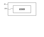
- FIG. 13 is a diagram illustrating an overview of a conversion device according to a fourth embodiment.
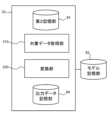
- FIG. 13 is a diagram illustrating a functional configuration of a conversion device according to a fourth embodiment.
- FIG. 13 is a diagram showing an overview of a conversion method according to a fourth embodiment.
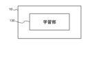
- (First embodiment) 1 is a diagram showing an overview of a model generating device 10 according to a first embodiment.
- the model generating device 10 includes a learning unit 130.
- the learning unit 130 generates a model by performing machine learning using a first image and a second image.
- the first image is an image generated using first radar signal data.
- the second image is an image generated using second radar signal data.
- the first radar signal data is a signal extracted from the second radar signal data.
- This model generation device 10 can produce a model that makes it possible to obtain high-resolution images regardless of the radar antenna configuration.
- model generation device 10 is described.
- the resolution of an image obtained by a radar that transmits and receives radio waves using multiple antennas usually depends on the antenna configuration. Specifically, the higher the frequency f of the radio waves transmitted and received by the antennas (or the wider the frequency band), the higher the resolution of the image obtained. Also, the more antennas the radar contains, the higher the resolution of the image obtained. Note that in a radar, multiple antennas are usually arranged at a predetermined interval (for example, ⁇ /2) based on the wavelength ⁇ of the radio waves transmitted and received by the antennas. Therefore, for a constant aperture size, the higher the frequency f, the greater the number of antennas.
- the radar aperture size is reduced to make it more compact, the number of antennas that can be included in the radar will be reduced.
- Another possibility is to reduce the number of antennas in order to lower the manufacturing costs of the radar. Therefore, technology that makes it possible to obtain high-resolution images even when using a radar with a small number of antennas is useful.
- FIG. 2 is a diagram illustrating a model 30 generated by the model generation device 10 according to this embodiment.
- the model generation device 10 according to this embodiment is a device that generates a model 30 that can increase the resolution of a radar image.
- a radar image is an image obtained by processing radar signal data obtained by a radar. Existing imaging processes can be used for the process of obtaining a radar image from radar signal data.
- An image is input to the model 30 as input data.
- the image input to the model 30 is also called an input image.
- the input image is a radar image.
- An image is output from the model 30 as output data.
- the image output from the model 30 is also called an output image.
- an output image with a higher resolution than the input image can be obtained.
- the model 30 is configured to include a neural network.
- the model generation device 10 according to this embodiment generates the model 30 by performing machine learning using training data in which a first image and a second image are combined.
- the second image has a higher resolution than the first image.
- the model generation device 10 uses the first image as input data to the model and the second image as correct answer data.
- the model 30 may be generated by a method other than a neural network.
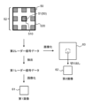
- FIG. 3 is a diagram for explaining a first image 61 and a second image 62 according to this embodiment.
- the first image 61 and the second image 62 are generated using a second radar 52.
- the second radar 52 includes a first radar 51 as a part of the second radar 52.
- the second radar 52 includes a plurality of subsets 50.
- the first radar 51 is one of the plurality of subsets 50 included in the second radar 52.
- the configurations of the second radar 52 and the first radar 51, and the relationship between the second radar 52 and the first radar 51 are not limited to the example in FIG. 3.
- the first radar 51 is a subset 50 located in the center of the second radar 52, but the first radar 51 may be a subset 50 located in another position.
- the first radar 51 consists of one subset 50, but the first radar 51 may be composed of two or more subsets 50.
- the first radar 51 does not include all of the subsets 50 included in the second radar 52.
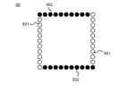
- FIG. 4 is a diagram illustrating an example of antenna arrangement in one subset 50.
- transmitting antennas 501 are indicated by white circles, and receiving antennas 502 are indicated by black circles.
- Subset 50 includes multiple transmitting antennas 501 and multiple receiving antennas 502.
- the transmitting antennas 501 and receiving antennas 502 are collectively referred to as antennas.
- the multiple antennas are arranged to form a rectangle.
- the multiple antennas are arranged so that one pair of opposing sides of the rectangle is depicted by a row of transmitting antennas 501, and the other pair of opposing sides is depicted by a row of receiving antennas 502.
- the first radar 51 and the second radar 52 transmit and receive radio waves in a predetermined frequency band.
- the first radar 51 and the second radar 52 are, for example, Stepped Frequency Continuous Wave (SFCW) type radars.
- the first radar 51 and the second radar 52 may be Frequency Modulated Continuous Wave (FMCW) type radars.
- the frequency of the radio waves transmitted by the transmitting antenna 501 changes stepwise or continuously within a predetermined frequency band.
- the distance between adjacent antennas is, for example, ⁇ /2, but is not limited to ⁇ /2.
- ⁇ is a wavelength corresponding to the highest frequency in the frequency band of the radio waves transmitted and received by the first radar 51 and the second radar 52. Note that the antenna arrangement in the subset 50 is not limited to the example in FIG. 4.
- the second radar 52 generates second radar signal data by transmitting and receiving radio waves.
- the second radar signal data includes multiple pieces of reception data based on the reception signals of the receiving antennas 502. Specifically, the multiple transmitting antennas 501 transmit radio waves at different times. All receiving antennas 502 included in the second radar 52 receive the radio waves transmitted from each transmitting antenna 501 and reflected by the target.
- the receiving antenna 502 may also receive radio waves transmitted from a transmitting antenna 501 included in a subset 50 different from that receiving antenna 502 and reflected by the target. In this way, reception data is obtained for all pairs of transmitting antennas 501 and receiving antennas 502 included in the second radar 52.
- the radar signal data of the second radar 52 includes all of this reception data.
- FIG. 5 is a diagram showing a first modified example of antenna arrangement in one subset 50.
- transmitting/receiving antennas 503 having both transmitting and receiving functions are arranged at the four corners. However, the transmitting and receiving functions of the transmitting/receiving antennas 503 are not operated simultaneously. While the transmitting/receiving antenna 503 is functioning as a receiving antenna, the transmitting/receiving antenna 503 does not function as a transmitting antenna. While the transmitting/receiving antenna 503 is functioning as a transmitting antenna, the transmitting/receiving antenna 503 does not function as a receiving antenna.
- FIG. 6 shows a second variant of the antenna arrangement in one subset 50.
- no antennas are arranged at the four corners.
- the direction in which the antennas are arranged is not particularly limited.
- the receiving antennas 502 may be arranged vertically, and the transmitting antennas 501 may be arranged horizontally.
- the number of receiving antennas 502 and transmitting antennas 501 is not limited to the examples shown in Figs. 4 to 6.
- the second radar signal data is signal data obtained by the second radar 52, which includes the first radar 51.
- the first radar signal data is signal data obtained by extracting data equivalent to the signal data of the first radar 51 from the second radar signal data. It can be said that the second radar signal data is data measured simultaneously with the first radar signal data.
- radio waves transmitted from a transmitting antenna 501 included in the first radar 51 and reflected by an object are received by a receiving antenna 502 included in the first radar 51, and the received data obtained is extracted from the second radar signal data. Then, first radar signal data including the extracted multiple received data is generated.
- the first radar signal data does not include received data based on radio waves transmitted by a transmitting antenna 501 not included in the first radar 51. Furthermore, the first radar signal data does not include received data based on radio waves received by a receiving antenna 502 not included in the first radar 51.
- the first radar signal data includes signal data for all or only a part of the frequency bands of the radio waves transmitted and received by the second radar. That is, data for all frequency bands may be extracted from the second radar signal data to form the first radar signal data, or data for some of the frequency bands may be extracted to form the first radar signal data. In the latter case, data other than the extracted part of the frequency bands is not included in the first radar signal data. In this way, the frequency band of the second radar signal data may be wider than the frequency band of the first radar signal data. That is, the frequency band of the radio waves transmitted and received by the first radar 51 may be virtually narrower than the frequency band of the radio waves transmitted and received by the second radar 52.
- the first image 61 is an image generated by performing imaging processing on the first radar signal data.
- an image 63 is obtained. Because the aperture 520 of the second radar 52 is larger than the aperture 510 of the first radar 51, the image 63 has a larger angle of view than the angle of view of the first image 61. Also, because the number of antennas included in the second radar 52 is greater than the number of antennas included in the first radar 51, the resolution of the image 63 is higher than the resolution of the first image 61.
- the second image 62 is an image obtained by cutting out a part of the image 63 generated using the second radar signal data. Specifically, the second image 62 is an image obtained by cutting out the area corresponding to the first image 61 from the radar image 63 generated using the second radar signal data. The position and size at which the second image 62 is cut out from the image 63 are determined based on the positional relationship and size relationship of the aperture 510 of the first radar 51 relative to the aperture 520 of the second radar 52. In this way, it is possible to obtain the first image 61 and the second image 62, which each capture the same target area. Furthermore, it is possible to obtain the second image 62, which has a higher resolution than the first image 61.
- the training data includes a first image 61 and a second image 62, both of which are obtained from the same second radar signal data.
- a model 30 can be obtained that can increase the resolution of radar images obtained by a radar with a small number of antennas.
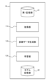
- FIG. 7 is a diagram illustrating an example of the functional configuration of the model generating device 10 according to this embodiment.
- the model generating device 10 further includes an acquisition unit 110, a first storage unit 81, and a model storage unit 82.
- the first storage unit 81 may be provided outside the model generating device 10.
- the model storage unit 82 may be provided outside the model generating device 10.
- the first storage unit 81 stores, for example, training data that combines the first image 61 and the second image 62.
- the training data can be prepared in advance and stored in the first storage unit 81.
- the model storage unit 82 holds information for constructing the model 30.
- the information for constructing the model 30 includes multiple parameters of the neural network.
- the acquisition unit 110 of the model generation device 10 reads and acquires the training data, i.e., the set of the first image 61 and the second image 62, from the first storage unit 81.
- the acquisition unit 110 may acquire the training data from another device. In that case, the first storage unit 81 does not need to be provided.
- the learning unit 130 updates the parameters stored in the model storage unit 82 by performing machine learning using the training data acquired by the acquisition unit 110.
- Machine learning can be performed using existing technology.
- the learning unit 130 inputs a first image 61 to the model 30 and obtains an output image from the model 30. Then, the learning unit 130 calculates a loss using the output image and a second image 62 that is included in the same training data as the first image 61 input to the model 30. Then, the parameters of the model 30 are updated so that the loss is reduced.
- the first memory unit 81 can hold multiple pieces of training data.
- the acquisition unit 110 can acquire multiple pieces of training data.
- the learning unit 130 repeatedly updates the parameters using the multiple pieces of training data. For example, the learning unit 130 repeats updating the parameters until a predetermined termination condition is satisfied.
- the predetermined termination condition is, for example, at least one of the following: the number of parameter updates reaches a predetermined number, and the loss becomes smaller than a predetermined criterion.
- Each functional component of the model generating device 10 acquisition unit 110 and learning unit 130 may be realized by hardware that realizes each functional component (e.g., hardwired electronic circuitry, etc.), or may be realized by a combination of hardware and software (e.g., a combination of an electronic circuitry and a program that controls it, etc.).
- acquisition unit 110 and learning unit 130 may be realized by hardware that realizes each functional component (e.g., hardwired electronic circuitry, etc.), or may be realized by a combination of hardware and software (e.g., a combination of an electronic circuitry and a program that controls it, etc.).
- a combination of hardware and software e.g., a combination of an electronic circuitry and a program that controls it, etc.
- FIG. 8 is a diagram illustrating a computer 1000 for realizing the model generating device 10.
- the computer 1000 is any computer.
- the computer 1000 is a SoC (System On Chip), a Personal Computer (PC), a server machine, a tablet terminal, or a smartphone.
- the computer 1000 may be a dedicated computer designed to realize the model generating device 10, or may be a general-purpose computer.
- the model generating device 10 may be realized by one computer 1000, or may be realized by a combination of multiple computers 1000.
- the computer 1000 has a bus 1020, a processor 1040, a memory 1060, a storage device 1080, an input/output interface 1100, and a network interface 1120.
- the bus 1020 is a data transmission path through which the processor 1040, the memory 1060, the storage device 1080, the input/output interface 1100, and the network interface 1120 transmit and receive data to each other.
- the processor 1040 is one of various processors, such as a CPU (Central Processing Unit), a GPU (Graphics Processing Unit), or an FPGA (Field-Programmable Gate Array).
- the memory 1060 is a main storage device realized using a RAM (Random Access Memory) or the like.
- Storage device 1080 is an auxiliary storage device realized using a hard disk, SSD (Solid State Drive), memory card, or ROM (Read Only Memory), etc.
- the input/output interface 1100 is an interface for connecting the computer 1000 to an input/output device.
- an input device such as a keyboard and an output device such as a display are connected to the input/output interface 1100.
- the input/output interface 1100 may be connected to the input device or output device by a wireless connection or a wired connection.
- the network interface 1120 is an interface for connecting the computer 1000 to a network.
- This communication network is, for example, a LAN (Local Area Network) or a WAN (Wide Area Network).
- the method for connecting the network interface 1120 to the network may be a wireless connection or a wired connection.
- the storage device 1080 stores program modules that realize each functional component of the model generating device 10.
- the processor 1040 reads each of these program modules into the memory 1060 and executes them to realize the function corresponding to each program module.
- the first storage unit 81 When the first storage unit 81 is provided inside the model generating device 10, the first storage unit 81 is realized, for example, by using the storage device 1080.
- the model storage unit 82 When the model storage unit 82 is provided inside the model generating device 10, the model storage unit 82 is realized, for example, by using the storage device 1080.
- FIG. 9 is a diagram showing an overview of the model generation method according to this embodiment.
- one or more computers generate a model 30 by performing machine learning using a first image 61 and a second image 62 (S11).
- the first image 61 is an image generated using the first radar signal data.
- the second image 62 is an image generated using the second radar signal data.
- the first radar signal data is a signal extracted from the second radar signal data.
- the learning unit 130 generates a model by performing machine learning using the first image 61 and the second image 62. Therefore, a model 30 is obtained that makes it possible to obtain a high-resolution image regardless of the antenna configuration of the radar.
- (Variation 1) 10 is a diagram illustrating a functional configuration of a model generation device 10 according to Modification 1.
- the model generation device 10 according to this modification is the same as the model generation device 10 according to the first embodiment, except for the points described below.
- the model generating device 10 includes a training data generating unit 120.
- the first storage unit 81 holds data for generating training data in advance. That is, the first storage unit 81 holds data for obtaining the first image 61 and the second image 62 in advance.
- the acquisition unit 110 in this modified example reads and acquires data for generating training data from the first storage unit 81.
- the training data generating unit 120 then generates training data (a set of the first image 61 and the second image 62) using the data acquired by the acquisition unit 110.
- the learning unit 130 generates a model 30 in the same manner as in the first embodiment, using the training data generated by the training data generating unit 120.
- the data for generating the training data is at least one of the second radar signal data, the first radar signal data, and the image 63. That is, the data for generating the training data may be only the second radar signal data, or may be a combination of the second radar signal data and the first radar signal data, or may be a combination of the second radar signal data and the image 63.
- the data for generating the training data may be a combination of the first radar signal data and the image 63.
- the data for generating the training data may be a combination of one of the first image 61 and the second image 62 and data for generating the other of the first image 61 and the second image 62.
- the second radar signal data data obtained from the second radar 52 can be stored in advance in the first storage unit 81.
- the first radar signal data and the image 63 can be generated and prepared by another information processing device or the like, and can be stored in advance in the first storage unit 81.
- the acquisition unit 110 may acquire data for generating training data from a radar or other information processing device. In that case, the first storage unit 81 may not be provided.
- the acquisition unit 110 and training data generation unit 120 for this modified example are described in detail below.
- the acquisition unit 110 acquires data for generating training data.
- the training data generation unit 120 When the acquisition unit 110 acquires the second radar signal data, the training data generation unit 120 generates at least one of the first image 61 and the second image 62 using the second radar signal data.
- the training data generation unit 120 extracts the first radar signal data from the second radar signal data as described above. Then, the training data generation unit 120 can generate the first image 61 by performing imaging processing on the first radar signal data.
- the training data generation unit 120 also performs imaging processing on the second radar signal data to generate an image 63, and extracts a second image 62 from the image 63. In this manner, the second image 62 can be generated.
- the training data generation unit 120 When the acquisition unit 110 acquires the first radar signal data, the training data generation unit 120 generates the first image 61 by performing imaging processing on the first radar signal data.
- the training data generation unit 120 cuts out the second image 62 from the image 63 to generate the second image 62.
- the training data generation unit 120 can generate training data.
- the first storage unit 81 can hold multiple pieces of data for generating training data.
- the acquisition unit 110 can acquire multiple pieces of data for generating training data.
- the training data generation unit 120 generates multiple pieces of training data.
- the learning unit 130 repeatedly updates the parameters using the multiple pieces of training data.
- the hardware configuration of the computer that realizes the model generating device 10 according to this modified example is, for example, shown in FIG. 8, similar to the model generating device 10.
- the storage device 1080 of the computer 1000 that realizes the model generating device 10 according to this modified example further stores a program module that realizes the functions of the training data generating unit 120.
- This modified example provides the same effects and advantages as the first embodiment.
- FIG. 1 An overview of the model generating device 10 according to the second embodiment is shown in Fig. 1, similarly to the first embodiment.
- Fig. 11 is a diagram for explaining a first image 61 and a second image 62 according to the present embodiment.
- the model generating device 10 according to the present embodiment is the same as the model generating device 10 according to the first embodiment, except for the points described below.
- the model generating device 10 includes a learning unit 130.
- the learning unit 130 generates the model 30 by performing machine learning using a first image 61 and a second image 62.
- the first image 61 is an image generated using first radar signal data obtained by the first radar 51.
- the second image 62 is an image generated using second radar signal data obtained by the second radar 52.
- the center frequency of the frequency band of radio waves transmitted and received by the second radar 52 is higher than the center frequency of the frequency band of radio waves transmitted and received by the first radar 51. This will be explained in detail below.
- the first radar 51 is not included in the second radar 52.
- the aperture 510 of the first radar 51 and the aperture 520 of the second radar 52 are provided independently of each other.
- the size of the aperture 520 of the second radar 52 may be the same as the size of the aperture 510 of the first radar 51.
- the angle of view of the first image 61 and the angle of view of the second image 62 are the same as each other.
- the number of antennas included in the second radar 52 may be greater than the number of antennas included in the first radar 51.
- the opening 510 of the first radar 51 may at least partially overlap with the opening 520 of the second radar 52. In other words, a part of the antenna of the first radar 51 may also serve as the antenna of the second radar 52.
- the radio waves transmitted and received by the second radar 52 are of a higher frequency than the radio waves transmitted and received by the first radar 51. Therefore, the second image 62 has a higher resolution than the first image 61.
- the center frequency of the frequency band of the radio waves transmitted and received by the second radar 52 is higher than the center frequency of the frequency band of the radio waves transmitted and received by the first radar 51. Note that the center frequency is the arithmetic mean of the highest and lowest frequencies in the frequency band.
- the relationship between the bandwidth of the frequency band of the radio waves transmitted and received by the first radar 51 and the bandwidth of the frequency band of the radio waves transmitted and received by the second radar 52 is not particularly limited.
- the bandwidth of the frequency band of the radio waves transmitted and received by the first radar 51 may be wider or narrower than the bandwidth of the frequency band of the radio waves transmitted and received by the second radar 52.
- the bandwidth of the frequency band of the radio waves transmitted and received by the first radar 51 may be the same as the bandwidth of the frequency band of the radio waves transmitted and received by the second radar 52.
- the first image 61 is generated by performing imaging processing on the first radar signal data obtained by the first radar 51.
- the second image 62 is generated by performing imaging processing on the second radar signal data obtained by the second radar 52.
- the first radar signal data and the second radar signal data are obtained by measuring substantially the same object (area) under substantially the same conditions by the first radar 51 and the second radar 52.
- a first image 61 and a second image 62 having a corresponding correlation with each other can be obtained.
- a first image 61 and a second image 62 capturing substantially the same object area can be obtained.
- the first radar 51 and the second radar 52 can be provided on the same board, and the measurement conditions and the like can be set and controlled.
- the frequency components of the second radar 52 are removed from the signal received by the first radar 51, and the frequency components of the first radar 51 are removed from the signal received by the second radar 52.
- the frequency band of the first radar 51 and the frequency band of the second radar 52 do not overlap.
- the training data includes a first image 61 and a second image 62 that have a corresponding correlation with each other.
- the training data includes a first image 61 and a second image 62 that were obtained by measuring approximately the same object (area) under approximately the same conditions using the first radar 51 and the second radar 52.
- a model 30 can be obtained that can increase the resolution of radar images obtained by a radar with a small number of antennas.
- the functional configuration of the model generating device 10 according to this embodiment is illustrated in FIG. 7, similar to the first embodiment.
- the acquisition unit 110 reads and acquires training data, i.e., a set of a first image 61 and a second image 62, from the first storage unit 81.
- the learning unit 130 updates the parameters of the model 30 stored in the model storage unit 82 by performing machine learning using the training data acquired by the acquisition unit 110.
- the first storage unit 81 can hold multiple pieces of training data.
- the acquisition unit 110 can acquire multiple pieces of training data.
- the learning unit 130 repeatedly updates the parameters using the multiple pieces of training data.
- FIG. 9 an overview of the model generation method according to this embodiment is shown in FIG. 9.
- one or more computers generate a model by performing machine learning using a first image 61 and a second image 62 (S11).
- the first image 61 is an image generated using first radar signal data obtained by the first radar 51.
- the second image 62 is an image generated using second radar signal data obtained by the second radar 52.
- the center frequency of the frequency band of radio waves transmitted and received by the second radar 52 is higher than the center frequency of the frequency band of radio waves transmitted and received by the first radar 51.
- the training data generation unit 120 When the acquisition unit 110 acquires the first radar signal data, the training data generation unit 120 generates a first image 61 by performing imaging processing on the first radar signal data. When the acquisition unit 110 acquires the second radar signal data, the training data generation unit 120 generates a second image 62 by performing imaging processing on the second radar signal data.
- the training data generation unit 120 can generate training data.
- the hardware configuration of the computer that realizes the model generating device 10 according to this modified example is, for example, shown in FIG. 8, similar to the model generating device 10.
- the storage device 1080 of the computer 1000 that realizes the model generating device 10 according to this modified example further stores a program module that realizes the functions of the training data generating unit 120.
- This modified example provides the same effects and advantages as the first embodiment.
- the learning unit 130 generates the model 30 by performing machine learning using a plurality of first images 61, which are a plurality of video frames, and a plurality of second images 62, which are also a plurality of video frames. This is explained in detail below.
- a video is input to the model 30 as input data.
- the model 30 outputs a video as output data.
- a plurality of images in time series i.e., a plurality of video frames
- the video input to the model 30 is also called an input video.
- the input video is a video made up of radar images.
- a plurality of images in time series i.e., a plurality of video frames, are output from the model 30 as output data.
- the video output from the model 30 is also called an output video.
- an output video with a higher resolution than the input video can be obtained.
- the resolution enhancement of each image is influenced by the images before and after that image. Therefore, the resolution enhancement of the video can be performed with greater accuracy.
- the model 30 is also configured to include a neural network.
- the model generation device 10 according to this embodiment generates the model 30 by performing machine learning using training data in which a first video and a second video are combined.
- the first video is a video made up of a plurality of first images 61.
- the second video is a video made up of a plurality of second images 62.
- the model generation device 10 uses the first video as input data to the model and the second video as ground truth data.
- Each first image 61 and each second image 62 in this embodiment is as described in the first or second embodiment.
- a plurality of first images 61 and a plurality of second images 62 are obtained.
- a first video and a second video are obtained.
- the functional configuration of the model generating device 10 according to this embodiment is illustrated in FIG. 7, as in the first and second embodiments.
- the functional configuration of the model generating device 10 according to this embodiment is illustrated in FIG. 10, as in Modification 1 and Modification 2.
- the learning unit 130 updates the parameters stored in the model storage unit 82 by performing machine learning using training data.
- Machine learning can be performed using existing technology.
- the learning unit 130 inputs a first video into the model 30 and obtains an output video from the model 30.
- the learning unit 130 calculates a loss using the output video and a second video included in the same training data as the first video input into the model 30.
- the learning unit 130 updates the parameters of the model 30 so as to reduce the loss.
- the learning unit 130 can repeatedly update the parameters using multiple training data.
- FIG. 14 is a diagram illustrating an example of the functional configuration of the conversion device 20 according to this embodiment.
- the conversion device 20 further includes a target data acquisition unit 210, a second storage unit 83, and an output data storage unit 84.
- the second storage unit 83 may be provided outside the conversion device 20.
- the output data storage unit 84 may be provided outside the conversion device 20.
- the conversion unit 230 may obtain multiple target images, which are multiple video frames, and input them to the model 30. In this way, the conversion unit 230 can obtain, as the output video, a video with a higher resolution than the input video.
- the second memory unit 83 is provided inside the conversion device 20
- the second memory unit 83 is realized, for example, by using the storage device 1080 of the computer 1000 that realizes the conversion device 20.
- the output data memory unit 84 is realized, for example, by using the storage device 1080 of the computer 1000 that realizes the conversion device 20.
- the model memory unit 82 is provided inside the conversion device 20
- the model memory unit 82 is realized, for example, by using the storage device 1080 of the computer 1000 that realizes the conversion device 20.
- FIG. 15 is a diagram showing an overview of the conversion method according to this embodiment.
- one or more computers use a model 30 to convert a target image (S21).
- the model 30 is a model 30 generated by a model generation device 10 according to at least any one of the first to third embodiments, modification 1, and modification 2.
- the conversion unit 230 converts the target image using the model 30. Therefore, the target image can be converted into an image with high resolution.
- a learning means for generating a model by performing machine learning using a first image and a second image the first image is an image generated using first radar signal data; the second image is an image generated using second radar signal data; The first radar signal data is a signal extracted from the second radar signal data.
- the second radar signal data is signal data obtained by a second radar including the first radar,
- the first radar signal data is signal data obtained by extracting data corresponding to the signal data of the first radar from the second radar signal data.
- a model generator wherein the aperture of the second radar is larger than the aperture of the first radar. 1-4.
- the model generating device according to any one of 1-1. to 1-4. A model generating device, wherein the second image is an image obtained by cutting out a portion of an image generated using the second radar signal data. 1-6.
- a model generating device wherein the second image is an image obtained by cutting out a region corresponding to the first image from an image generated using the second radar signal data. 1-7.
- the second image is a higher resolution model than the first image. 1-8.
- the learning means is a model generation device that generates a model by performing machine learning using a plurality of the first images, which are a plurality of video frames, and a plurality of the second images, which are a plurality of video frames. 2-1.
- a conversion device including a conversion means for converting a target image using a model generated by the model generation device according to any one of 2-1. to 2-4. 3-4.
- the conversion device according to 3-2. or 3-3. A conversion device in which the target image is an image obtained by a radar having the same configuration as the first radar. 4-1.
- One or more computers perform machine learning using the first image and the second image to generate a model; the first image is an image generated using first radar signal data; the second image is an image generated using second radar signal data; The method of claim 1, wherein the first radar signal data is a signal extracted from the second radar signal data. 4-2.
- a model generation method in which the one or more computers generate the model by performing machine learning using a plurality of the first images, which are a plurality of video frames, and a plurality of the second images, which are a plurality of video frames.
- One or more computers perform machine learning using the first image and the second image to generate a model; the first image is an image generated using first radar signal data obtained by a first radar, the second image is an image generated using second radar signal data obtained by a second radar, A model generation method in which the center frequency of the frequency band of radio waves transmitted and received by the second radar is higher than the center frequency of the frequency band of radio waves transmitted and received by the first radar.
- the conversion method according to 6-2. or 6-3. A transformation method in which the target image is an image obtained by a radar having the same configuration as the first radar. 7-1.
- the first image is an image generated using first radar signal data;
- the second image is an image generated using second radar signal data;
- the first radar signal data is a signal extracted from the second radar signal data. 7-2.
- the second radar signal data is signal data obtained by a second radar including the first radar,
- the first radar signal data is signal data obtained by extracting data corresponding to the signal data of the first radar from the second radar signal data. 7-3.
- the aperture of the second radar is larger than the aperture of the first radar. 7-4.
- the program according to 7-2 In the program according to 7-2.
- the second image is an image obtained by cutting out a portion of an image generated using the second radar signal data. 7-6.
- the second image is an image obtained by cutting out a region corresponding to the first image from an image generated using the second radar signal data. 7-7.
- the second image is a higher resolution image than the first image. 7-8.
- the learning means is a program that generates a model by performing machine learning using a plurality of the first images, which are a plurality of video frames, and a plurality of the second images, which are a plurality of video frames.
- 8-1 Allowing the computer to function as a learning means for generating a model by performing machine learning using the first image and the second image; the first image is an image generated using first radar signal data obtained by a first radar, the second image is an image generated using second radar signal data obtained by a second radar, A program in which the center frequency of the frequency band of radio waves transmitted and received by the second radar is higher than the center frequency of the frequency band of radio waves transmitted and received by the first radar. 8-2.
- the aperture size of the second radar is the same as the aperture size of the first radar. 8-3.
- the second image is a higher resolution image than the first image. 8-4.
- the learning means is a program that generates a model by performing machine learning using a plurality of the first images, which are a plurality of video frames, and a plurality of the second images, which are a plurality of video frames.
- the target image is an image obtained by a radar having the same configuration as the first radar.
- Model generation device 20 Conversion device 30 Model 50 Subset 51 First radar 52 Second radar 61 First image 62 Second image 81 First memory unit 82 Model memory unit 83 Second memory unit 84 Output data memory unit 110 Acquisition unit 120 Training data generation unit 130 Learning unit 210 Target data acquisition unit 230 Conversion unit 501 Transmitting antenna 502 Receiving antenna 503 Transmitting and receiving antennas 510, 520 Aperture 1000 Computer
Landscapes
- Engineering & Computer Science (AREA)
- Remote Sensing (AREA)
- Radar, Positioning & Navigation (AREA)
- Physics & Mathematics (AREA)
- Computer Networks & Wireless Communication (AREA)
- General Physics & Mathematics (AREA)
- Electromagnetism (AREA)
- Radar Systems Or Details Thereof (AREA)
Abstract
モデル生成装置は、学習部を備える。学習部は、第1画像と第2画像を用いて機械学習を行うことでモデルを生成する。第1画像は第1レーダー信号データを用いて生成された画像である。第2画像は第2レーダー信号データを用いて生成された画像である。第1レーダー信号データは、第2レーダー信号データから抽出された信号である。
Description
本発明は、モデル生成装置、変換装置、モデル生成方法、およびプログラムに関する。
レーダーによれば、対象に対して電波を送受信し、対象を画像化することができる。
特許文献1には、レーダーを用いて、対象者が危険物を所持している可能性を判定する技術について記載されている。また、特許文献1には、一次スクリーニングよりも高精度な検出が可能であるレーダーを用いて二次スクリーニングを行うことが記載されている。
しかし、上述した特許文献1においては、レーダーで得られる画像の解像度は、そのレーダーのアンテナ数や周波数に依存していた。
本発明の目的の一例は、上述した課題を鑑み、レーダーのアンテナ構成に関わらず、高解像度の画像を得ることを可能とするモデル生成装置、変換装置、モデル生成方法、およびプログラムを提供することにある。
本発明の一態様によれば、
第1画像と第2画像を用いて機械学習を行うことでモデルを生成する学習手段を備え、
前記第1画像は第1レーダー信号データを用いて生成された画像であり、
前記第2画像は第2レーダー信号データを用いて生成された画像であり、
前記第1レーダー信号データは、前記第2レーダー信号データから抽出された信号である
モデル生成装置が提供される。
第1画像と第2画像を用いて機械学習を行うことでモデルを生成する学習手段を備え、
前記第1画像は第1レーダー信号データを用いて生成された画像であり、
前記第2画像は第2レーダー信号データを用いて生成された画像であり、
前記第1レーダー信号データは、前記第2レーダー信号データから抽出された信号である
モデル生成装置が提供される。
本発明の一態様によれば、
上記のモデル生成装置で生成されたモデルを用いて、対象画像を変換する変換手段を備える
変換装置が提供される。
上記のモデル生成装置で生成されたモデルを用いて、対象画像を変換する変換手段を備える
変換装置が提供される。
本発明の一態様によれば、
一以上のコンピュータが、第1画像と第2画像を用いて機械学習を行うことでモデルを生成し、
前記第1画像は第1レーダー信号データを用いて生成された画像であり、
前記第2画像は第2レーダー信号データを用いて生成された画像であり、
前記第1レーダー信号データは、前記第2レーダー信号データから抽出された信号である
モデル生成方法が提供される。
一以上のコンピュータが、第1画像と第2画像を用いて機械学習を行うことでモデルを生成し、
前記第1画像は第1レーダー信号データを用いて生成された画像であり、
前記第2画像は第2レーダー信号データを用いて生成された画像であり、
前記第1レーダー信号データは、前記第2レーダー信号データから抽出された信号である
モデル生成方法が提供される。
本発明の一態様によれば、
一以上のコンピュータが、上記のモデル生成装置で生成されたモデルを用いて、対象画像を変換する
変換方法が提供される。
一以上のコンピュータが、上記のモデル生成装置で生成されたモデルを用いて、対象画像を変換する
変換方法が提供される。
本発明の一態様によれば、
プログラムを記録しているコンピュータ読み取り可能な記録媒体であって、
前記プログラムは、コンピュータを、第1画像と第2画像を用いて機械学習を行うことでモデルを生成する学習手段として機能させ、
前記第1画像は第1レーダー信号データを用いて生成された画像であり、
前記第2画像は第2レーダー信号データを用いて生成された画像であり、
前記第1レーダー信号データは、前記第2レーダー信号データから抽出された信号である
記録媒体が提供される。
プログラムを記録しているコンピュータ読み取り可能な記録媒体であって、
前記プログラムは、コンピュータを、第1画像と第2画像を用いて機械学習を行うことでモデルを生成する学習手段として機能させ、
前記第1画像は第1レーダー信号データを用いて生成された画像であり、
前記第2画像は第2レーダー信号データを用いて生成された画像であり、
前記第1レーダー信号データは、前記第2レーダー信号データから抽出された信号である
記録媒体が提供される。
本発明の一態様によれば、レーダーのアンテナ構成に関わらず、高解像度の画像を得ることを可能とするモデル生成装置、変換装置、モデル生成方法、およびプログラムを、提供できる。
以下、本発明の実施の形態について、図面を用いて説明する。なお、全ての図面において、同様な構成要素には同様の符号を付し、適宜説明を省略する。
(第1の実施形態)
図1は、第1の実施形態に係るモデル生成装置10の概要を示す図である。モデル生成装置10は、学習部130を備える。学習部130は、第1画像と第2画像を用いて機械学習を行うことでモデルを生成する。第1画像は第1レーダー信号データを用いて生成された画像である。第2画像は第2レーダー信号データを用いて生成された画像である。第1レーダー信号データは、第2レーダー信号データから抽出された信号である。
図1は、第1の実施形態に係るモデル生成装置10の概要を示す図である。モデル生成装置10は、学習部130を備える。学習部130は、第1画像と第2画像を用いて機械学習を行うことでモデルを生成する。第1画像は第1レーダー信号データを用いて生成された画像である。第2画像は第2レーダー信号データを用いて生成された画像である。第1レーダー信号データは、第2レーダー信号データから抽出された信号である。
このモデル生成装置10によれば、レーダーのアンテナ構成に関わらず、高解像度の画像を得ることを可能とするモデルが得られる。
以下、モデル生成装置10の詳細例について説明する。
複数のアンテナにより電波を送受信するレーダーで、得られる画像の解像度は、通常、アンテナ構成に依存する。具体的には、アンテナが送受信する電波の周波数fが高いほど(または周波数帯域が広いほど)、得られる画像の解像度は高くなる。また、レーダーに含まれるアンテナの数が多いほど、得られる画像の解像度は高くなる。なお、レーダーにおいて複数のアンテナは通常、アンテナが送受信する電波の波長λに基づく所定の間隔(たとえばλ/2)で配置される。したがって、開口サイズが一定である場合、周波数fを高くするほど、アンテナ数が多くなる。
ここで、たとえば、小型化のためにレーダーの開口サイズを小さくする場合、レーダーに含める事ができるアンテナの数は少なくなる。他にも、たとえば、レーダーの製造コストを下げるためにアンテナ数を減らすことが考えられる。したがって、少ないアンテナ数のレーダーを用いた場合でも、高解像度の画像を得ることを可能とする技術が有用である。
図2は、本実施形態に係るモデル生成装置10が生成するモデル30を例示する図である。本実施形態に係るモデル生成装置10は、レーダー画像を高解像度化できるモデル30を生成する装置である。なお、レーダー画像は、レーダーで得られたレーダー信号データを処理することにより得られる画像である。レーダー信号データからレーダー画像を得るための処理には、既存の画像化処理を用いることができる。モデル30には、入力データとして画像が入力される。モデル30に入力される画像を、入力画像とも呼ぶ。入力画像は、レーダー画像である。モデル30からは、出力データとして画像が出力される。モデル30から出力される画像を出力画像とも呼ぶ。モデル30を用いることで、入力画像よりも高解像度の出力画像が得られる。
モデル30は、ニューラルネットワークを含んで構成される。本実施形態に係るモデル生成装置10は、第1画像と第2画像とが組み合わされた訓練データを用いて機械学習を行うことで、モデル30を生成する。ここで、第2画像は第1画像よりも高解像度である。モデル生成装置10は、機械学習において、第1画像をモデルへの入力データとし、第2画像を正解データとして用いる。ただし、モデル30は、ニューラルネットワーク以外の方法により生成されていてもよい。
図3は、本実施形態に係る第1画像61および第2画像62について説明するための図である。第1画像61および第2画像62は、第2レーダー52を用いて生成される。ここで、第2レーダー52は、第2レーダー52の一部として第1レーダー51を含む。図3の例において、第2レーダー52は、複数のサブセット50を含む。図3の例において、第1レーダー51は、第2レーダー52に含まれる複数のサブセット50のうちの一つである。
ただし、第2レーダー52および第1レーダー51の構成、および第2レーダー52と第1レーダー51の関係は図3の例に限定されない。たとえば、図3の例では、第1レーダー51は、第2レーダー52の中央に位置するサブセット50であるが、第1レーダー51は、他の位置にあるサブセット50であってもよい。また、図3の例では、第1レーダー51は一つのサブセット50からなるが、第1レーダー51は、二つ以上のサブセット50からなってもよい。ただし、第1レーダー51は、第2レーダー52に含まれるサブセット50を全ては含まない。
図4は、一つのサブセット50におけるアンテナ配置を例示する図である。図4において、送信アンテナ501は白丸で、受信アンテナ502は黒丸で示されている。サブセット50には、複数の送信アンテナ501と、複数の受信アンテナ502が含まれる。送信アンテナ501と受信アンテナ502を総称してアンテナと呼ぶ。サブセット50において、複数のアンテナは、四角形を描くように配置されている。この四角形のうち、一組の対向する二辺が送信アンテナ501の列で描かれ、他の一組の対向する二辺が受信アンテナ502の列で描かれるように、複数のアンテナが配置されている。
第1レーダー51および第2レーダー52は、所定の周波数帯域の電波を送受信する。第1レーダー51および第2レーダー52はたとえば、Stepped Frequency Continuous Wave (SFCW)方式のレーダーである。または、第1レーダー51および第2レーダー52は、Frequency Modulated Continuous Wave (FMCW)方式のレーダーであってもよい。送信アンテナ501が送信する電波の周波数は、所定の周波数帯域内で、段階的にまたは連続的に変化する。サブセット50において、隣り合うアンテナ間の距離は、たとえばλ/2であるが、λ/2に限定されない。λは、第1レーダー51および第2レーダー52が送受信する電波の周波数帯域の最高周波数に対応する波長である。なお、サブセット50におけるアンテナ配置は図4の例に限定されない。
第2レーダー52では、電波を送受信することで、第2レーダー信号データが生成される。第2レーダー信号データは、受信アンテナ502の受信信号に基づく受信データを複数含んで構成される。具体的には、複数の送信アンテナ501は、互いに異なるタイミングで電波を送信する。各送信アンテナ501から送信され、対象で反射された電波を第2レーダー52に含まれる全ての受信アンテナ502が受信する。受信アンテナ502は、その受信アンテナ502とは異なるサブセット50に含まれる送信アンテナ501から送信され、対象で反射された電波も受信してよい。そうすることで、第2レーダー52に含まれる送信アンテナ501と受信アンテナ502の全てのペアについて、受信データが得られる。第2レーダー52のレーダー信号データは、これら全ての受信データを含んで構成される。
図5は、一つのサブセット50におけるアンテナ配置の第1の変形例を示す図である。第1の変形例では、送信と受信の両方の機能を有する送受信アンテナ503が四隅に配置されている。ただし、送受信アンテナ503の送信機能と受信機能とを同時に動作させることはない。送受信アンテナ503を受信アンテナとして機能させている間は、送受信アンテナ503を送信アンテナとしては機能させない。送受信アンテナ503を送信アンテナとして機能させている間は、送受信アンテナ503を受信アンテナとしては機能させない。
図6は、一つのサブセット50におけるアンテナ配置の第2の変形例を示す図である。第2の変形例では、四隅にはいずれのアンテナも配置されていない。
なお、図4から図6のいずれの場合にも、アンテナを並べる方向は特に限定されない。受信アンテナ502を縦方向に並べ、送信アンテナ501を横方向に並べてもよい。また、受信アンテナ502および送信アンテナ501の個数は図4から図6の例に限定されない。
図3に戻り、第1画像61および第2画像62についてさらに説明する。上述した通り、第2レーダー信号データは、第1レーダー51を含む第2レーダー52で得られる信号データである。そして、第1レーダー信号データは、第1レーダー51の信号データに相当するデータを、第2レーダー信号データから抽出することで得られる信号データである。第2レーダー信号データは、第1レーダー信号データと同時に測定されたデータであると言える。
具体的には、第1レーダー51に含まれる送信アンテナ501から送信され対象で反射された電波を、第1レーダー51に含まれる受信アンテナ502で受信して得られた受信データが、第2レーダー信号データから抽出される。そして、抽出された複数の受信データを含む第1レーダー信号データが生成される。第1レーダー信号データには、第1レーダー51に含まれない送信アンテナ501で送信された電波による受信データは含まれない。また、第1レーダー信号データには、第1レーダー51に含まれない受信アンテナ502で受信された電波による受信データは含まれない。
第1レーダー信号データには、第2レーダーが送受信する電波の周波数帯域のうち、全てまたは一部のみの周波数帯域についての信号データが含まれる。すなわち、第2レーダー信号データのうち、全ての周波数帯域についてのデータを抽出して第1レーダー信号データとしてもよいし、一部の周波数帯域についてのデータを抽出して第1レーダー信号データとしてもよい。後者の場合、抽出された一部の周波数帯域についてのデータ以外は第1レーダー信号データには含まれない。このように、第2レーダー信号データの周波数帯域を、第1レーダー信号データの周波数帯域より広くしてもよい。すなわち、第1レーダー51が送受信する電波の周波数帯域を、仮想的に、第2レーダー52が送受信する電波の周波数帯域より狭くしてもよい。
第1画像61は第1レーダー信号データに対し、画像化処理を行うことにより、生成される画像である。
また、第2レーダー信号データを同様に画像化処理することで、画像63が得られる。第2レーダー52の開口520は、第1レーダー51の開口510より大きいことから、画像63は、第1画像61の画角よりも大きな画角を有する。また、第2レーダー52に含まれるアンテナの数は第1レーダー51に含まれるアンテナの数よりも多いことから、画像63の解像度は、第1画像61の解像度よりも高い。
第2画像62は、第2レーダー信号データを用いて生成された画像63の一部を切り出した画像である。具体的には、第2画像62は、第2レーダー信号データを用いて生成されたレーダー画像63のうち、第1画像61に相当する領域を切り出した画像である。第2レーダー52の開口520に対する第1レーダー51の開口510の、位置関係、および大きさの関係に基づいて、画像63から第2画像62を切り出す位置および大きさが定められる。このようにして、互いに同じ対象領域を撮像した第1画像61と第2画像62を得ることができる。なおかつ、第1画像61よりも高い解像度の第2画像62を得られる。
訓練データには、互いに同じ第2レーダー信号データから得られた第1画像61と第2画像62とが含まれる。
このような訓練データを用いることで、少ないアンテナ数のレーダーで得られたレーダー画像を高解像度化する事ができるモデル30が得られる。
図7は、本実施形態に係るモデル生成装置10の機能構成を例示する図である。図7の例において、モデル生成装置10は、取得部110、第1記憶部81およびモデル記憶部82をさらに備える。ただし、第1記憶部81は、モデル生成装置10の外部に設けられていてもよい。また、モデル記憶部82は、モデル生成装置10の外部に設けられていてもよい。
第1記憶部81はたとえば、第1画像61および第2画像62を組み合わせた訓練データを保持している。訓練データは予め準備して第1記憶部81に保持させることができる。
モデル記憶部82は、モデル30を構成するための情報を保持している。モデル30を構成するための情報には、ニューラルネットワークの複数のパラメータが含まれる。
モデル生成装置10の取得部110は、第1記憶部81から訓練データを、すなわち第1画像61および第2画像62の組を、読み出して取得する。ただし、取得部110は、他の装置から訓練データを取得してもよい。その場合、第1記憶部81は設けられていなくてもよい。
学習部130は、取得部110が取得した訓練データを用いて機械学習を行うことでモデル記憶部82に保持されたパラメータを更新する。機械学習は、既存の技術を用いて行える。たとえば、学習部130は、第1画像61をモデル30に入力し、モデル30からの出力画像を得る。そして、その出力画像と、モデル30に入力した第1画像61と同じ訓練データに含まれる第2画像62とを用いて損失(Loss)を算出する。そして、損失が小さくなるようにモデル30のパラメータを更新する。
第1記憶部81は、訓練データを複数保持することができる。そして、取得部110は、複数の訓練データを取得することができる。学習部130は、複数の訓練データを用いてパラメータの更新を繰り返す。たとえば、学習部130は、所定の終了条件が満たされるまで、パラメータの更新を繰り返す。所定の終了条件はたとえば、パラメータの更新回数が所定の回数となること、および、損失が所定の基準より小さくなることの少なくとも一方である。
モデル生成装置10のハードウエア構成について以下に説明する。モデル生成装置10の各機能構成部(取得部110および学習部130)は、各機能構成部を実現するハードウエア(例:ハードワイヤードされた電子回路など)で実現されてもよいし、ハードウエアとソフトウエアとの組み合わせ(例:電子回路とそれを制御するプログラムの組み合わせなど)で実現されてもよい。以下、モデル生成装置10の各機能構成部がハードウエアとソフトウエアとの組み合わせで実現される場合について、さらに説明する。
図8は、モデル生成装置10を実現するための計算機1000を例示する図である。計算機1000は任意の計算機である。たとえば計算機1000は、SoC(System On Chip)、Personal Computer(PC)、サーバマシン、タブレット端末、またはスマートフォンなどである。計算機1000は、モデル生成装置10を実現するために設計された専用の計算機であってもよいし、汎用の計算機であってもよい。また、モデル生成装置10は、一つの計算機1000で実現されても良いし、複数の計算機1000の組み合わせにより実現されても良い。
計算機1000は、バス1020、プロセッサ1040、メモリ1060、ストレージデバイス1080、入出力インタフェース1100、およびネットワークインタフェース1120を有する。バス1020は、プロセッサ1040、メモリ1060、ストレージデバイス1080、入出力インタフェース1100、およびネットワークインタフェース1120が、相互にデータを送受信するためのデータ伝送路である。ただし、プロセッサ1040などを互いに接続する方法は、バス接続に限定されない。プロセッサ1040は、CPU(Central Processing Unit)、GPU(Graphics Processing Unit)、または FPGA(Field-Programmable Gate Array)などの種々のプロセッサである。メモリ1060は、RAM(Random Access Memory)などを用いて実現される主記憶装置である。ストレージデバイス1080は、ハードディスク、SSD(Solid State Drive)、メモリカード、または ROM(Read Only Memory)などを用いて実現される補助記憶装置である。
入出力インタフェース1100は、計算機1000と入出力デバイスとを接続するためのインタフェースである。たとえば入出力インタフェース1100には、キーボードなどの入力装置や、ディスプレイなどの出力装置が接続される。入出力インタフェース1100が入力装置や出力装置に接続する方法は、無線接続であってもよいし、有線接続であってもよい。
ネットワークインタフェース1120は、計算機1000をネットワークに接続するためのインタフェースである。この通信網は、たとえば LAN(Local Area Network)や WAN(Wide Area Network)である。ネットワークインタフェース1120がネットワークに接続する方法は、無線接続であってもよいし、有線接続であってもよい。
ストレージデバイス1080は、モデル生成装置10の各機能構成部を実現するプログラムモジュールを記憶している。プロセッサ1040は、これら各プログラムモジュールをメモリ1060に読み出して実行することで、各プログラムモジュールに対応する機能を実現する。
また、第1記憶部81がモデル生成装置10の内部に設けられる場合、たとえば第1記憶部81はストレージデバイス1080を用いて実現される。モデル記憶部82がモデル生成装置10の内部に設けられる場合、たとえばモデル記憶部82はストレージデバイス1080を用いて実現される。
図9は、本実施形態に係るモデル生成方法の概要を示す図である。本実施形態に係るモデル生成方法では、一以上のコンピュータが、第1画像61と第2画像62を用いて機械学習を行うことでモデル30を生成する(S11)。第1画像61は第1レーダー信号データを用いて生成された画像である。第2画像62は第2レーダー信号データを用いて生成された画像である。第1レーダー信号データは、第2レーダー信号データから抽出された信号である。
以上、本実施形態によれば、学習部130は、第1画像61と第2画像62を用いて機械学習を行うことでモデルを生成する。したがって、レーダーのアンテナ構成に関わらず、高解像度の画像を得ることを可能とするモデル30が得られる。
(変形例1)
図10は、変形例1に係るモデル生成装置10の機能構成を例示する図である。本変形例に係るモデル生成装置10は、以下に説明する点を除いて、第1の実施形態に係るモデル生成装置10と同じである。
図10は、変形例1に係るモデル生成装置10の機能構成を例示する図である。本変形例に係るモデル生成装置10は、以下に説明する点を除いて、第1の実施形態に係るモデル生成装置10と同じである。
本変形例において、モデル生成装置10は、訓練データ生成部120を備える。第1記憶部81は、訓練データを生成するためのデータを予め保持している。すなわち、第1記憶部81は、第1画像61および第2画像62を得るためのデータを予め保持している。本変形例に係る取得部110は、第1記憶部81から、訓練データを生成するためのデータを読み出して取得する。そして、訓練データ生成部120は、取得部110が取得したデータを用いて訓練データ(第1画像61と第2画像62とのセット)を生成する。学習部130は、訓練データ生成部120が生成した訓練データを用いて第1の実施形態と同様にモデル30を生成する。
訓練データを生成するためのデータは、第2レーダー信号データ、第1レーダー信号データ、および画像63の少なくともいずれかである。すなわち、訓練データを生成するためのデータは、第2レーダー信号データのみであってもよいし、第2レーダー信号データと第1レーダー信号データとの組み合わせであってもよいし、第2レーダー信号データと画像63との組み合わせであってもよい。訓練データを生成するためのデータは、第1レーダー信号データと画像63との組み合わせであってもよい。または、訓練データを生成するためのデータは、第1画像61および第2画像62の一方と、第1画像61および第2画像62の他方を生成するためのデータとの組み合わせであってもよい。
第2レーダー信号データとしては、第2レーダー52から得たデータを、予め第1記憶部81に保持させることができる。第1レーダー信号データ、および画像63は、他の情報処理装置等で生成して準備し、予め第1記憶部81に保持させることができる。
ただし、取得部110は、訓練データを生成するためのデータを、レーダーまたは他の情報処理装置から取得してもよい。その場合、第1記憶部81は設けられていなくてもよい。
本変形例に係る取得部110および訓練データ生成部120について以下に詳しく説明する。
取得部110は、訓練データを生成するためのデータを取得する。
取得部110が、第2レーダー信号データを取得する場合、訓練データ生成部120は、第2レーダー信号データを用いて第1画像61および第2画像62の少なくとも一方を生成する。
具体的には、訓練データ生成部120は、第2レーダー信号データから、上述したように第1レーダー信号データを抽出する。そして、訓練データ生成部120は、第1レーダー信号データに対し画像化処理を行うことで第1画像61を生成できる。
また、訓練データ生成部120は、第2レーダー信号データに対し画像化処理を行うことで画像63を生成し、画像63から第2画像62を切り出す。このようにして、第2画像62を生成できる。
取得部110が、第1レーダー信号データを取得する場合、訓練データ生成部120は、第1レーダー信号データに対し画像化処理を行うことで第1画像61を生成する。
取得部110が、画像63を取得する場合、訓練データ生成部120は、画像63から第2画像62を切り出して、第2画像62を生成する。
このようにして、訓練データ生成部120は、訓練データを生成できる。
なお、第1記憶部81は、訓練データを生成するためのデータを複数保持することができる。そして、取得部110は、訓練データを生成するためのデータを複数取得することができる。訓練データ生成部120は、複数の訓練データを生成する。そして、第1の実施形態と同様、学習部130は、複数の訓練データを用いてパラメータの更新を繰り返す。
本変形例に係るモデル生成装置10を実現する計算機のハードウエア構成は、モデル生成装置10と同様に、たとえば図8によって表される。ただし、本変形例に係るモデル生成装置10を実現する計算機1000のストレージデバイス1080には、訓練データ生成部120の機能を実現するプログラムモジュールがさらに記憶される。
本変形例によれば、第1の実施形態と同様の作用および効果が得られる。
(第2の実施形態)
第2の実施形態に係るモデル生成装置10の概要は、第1の実施形態と同様、図1で示される。図11は、本実施形態に係る第1画像61および第2画像62について説明するための図である。本実施形態に係るモデル生成装置10は、以下に説明する点を除いて第1の実施形態に係るモデル生成装置10と同じである。
第2の実施形態に係るモデル生成装置10の概要は、第1の実施形態と同様、図1で示される。図11は、本実施形態に係る第1画像61および第2画像62について説明するための図である。本実施形態に係るモデル生成装置10は、以下に説明する点を除いて第1の実施形態に係るモデル生成装置10と同じである。
本実施形態に係るモデル生成装置10は、学習部130を備える。学習部130は、第1画像61と第2画像62を用いて機械学習を行うことでモデル30を生成する。第1画像61は第1レーダー51で得られた第1レーダー信号データを用いて生成された画像である。第2画像62は第2レーダー52で得られた第2レーダー信号データを用いて生成された画像である。本実施形態において、第2レーダー52が送受信する電波の周波数帯域の中心周波数は、第1レーダー51が送受信する電波の周波数帯域の中心周波数より高い。以下に詳しく説明する。
本実施形態において、第1レーダー51は第2レーダー52に含まれていない。図11の例において、第1レーダー51の開口510と第2レーダー52の開口520とは互いに独立に設けられている。本実施形態において、第2レーダー52の開口520のサイズは、第1レーダー51の開口510のサイズと同じであってよい。この場合、第1画像61の画角と第2画像62の画角とは、互いに同じとなる。
第2レーダー52に含まれるアンテナの数は、第1レーダー51に含まれるアンテナの数より多くてよい。第1レーダー51の開口510は、少なくとも一部が第2レーダー52の開口520に重なっていてもよい。すなわち、第1レーダー51のアンテナの一部は第2レーダー52のアンテナを兼ねていてもよい。
本実施形態において、第2レーダー52が送受信する電波は、第1レーダー51が送受信する電波より高周波である。したがって、第2画像62は第1画像61よりも高解像度である。具体的には、上述した通り、第2レーダー52が送受信する電波の周波数帯域の中心周波数は、第1レーダー51が送受信する電波の周波数帯域の中心周波数より高い。なお、中心周波数とは、周波数帯域の最高周波数と最低周波数との相加平均である。
第2画像62が第1画像61よりも高解像度である限り、第1レーダー51が送受信する電波の周波数帯域の帯域幅と、第2レーダー52が送受信する電波の周波数帯域の帯域幅との関係は特に限定されない。すなわち、第1レーダー51が送受信する電波の周波数帯域の帯域幅は、第2レーダー52が送受信する電波の周波数帯域の帯域幅よりも広くてもよいし、狭くてもよい。または、第1レーダー51が送受信する電波の周波数帯域の帯域幅は、第2レーダー52が送受信する電波の周波数帯域の帯域幅と同じであってもよい。
第1画像61は、第1レーダー51で得られた第1レーダー信号データを画像化処理することで生成される。第2画像62は、第2レーダー52で得られた第2レーダー信号データを画像化処理することで生成される。
第1レーダー信号データと第2レーダー信号データは、第1レーダー51と第2レーダー52とにより、ほぼ同じ対象(領域)を、ほぼ同じ条件で測定することで得られる。そうすることで、互いに対応する相関性を有する第1画像61および第2画像62が得られる。たとえば、互いにほぼ同じ対象領域を撮像した第1画像61と第2画像62を得ることができる。たとえば、第1レーダー51と第2レーダー52とは同じボード上に設けられ、計測条件等が設定および制御されうる。なお、干渉を避けるため、第1レーダー51と第2レーダー52の測定タイミングはわずかにずらすことが好ましい。または、受信アンテナ502による受信信号から、フィルタ等を用いて干渉の原因となる周波数成分を除去することが好ましい。すなわち、第1レーダー51の受信信号から第2レーダー52の周波数成分を除去し、第2レーダー52の受信信号から第1レーダー51の周波数成分を除去する。この場合、第1レーダー51の周波数帯域と、第2レーダー52の周波数帯域とは、重ならないことが好ましい。
訓練データには、互いに対応する相関性を有する第1画像61と第2画像62とが含まれる。すなわち、訓練データには、第1レーダー51と第2レーダー52とにより、ほぼ同じ対象(領域)を、ほぼ同じ条件で測定することで得られた第1画像61と第2画像62とが含まれる。
このような訓練データを用いることで、少ないアンテナ数のレーダーで得られたレーダー画像を高解像度化する事ができるモデル30が得られる。
本実施形態に係るモデル生成装置10の機能構成は、第1の実施形態と同様に、図7で例示される。第1の実施形態と同様に、取得部110は、第1記憶部81から訓練データを、すなわち第1画像61および第2画像62の組を、読み出して取得する。学習部130は、取得部110が取得した訓練データを用いて機械学習を行うことでモデル記憶部82に保持されたモデル30のパラメータを更新する。
また、第1の実施形態と同様に、第1記憶部81は、訓練データを複数保持することができる。そして、取得部110は、複数の訓練データを取得することができる。学習部130は、複数の訓練データを用いてパラメータの更新を繰り返す。
本実施形態に係るモデル生成方法の概要は、第1の実施形態と同様、図9で示される。本実施形態に係るモデル生成方法では、一以上のコンピュータが、第1画像61と第2画像62を用いて機械学習を行うことでモデルを生成する(S11)。第1画像61は第1レーダー51で得られた第1レーダー信号データを用いて生成された画像である。第2画像62は第2レーダー52で得られた第2レーダー信号データを用いて生成された画像である。第2レーダー52が送受信する電波の周波数帯域の中心周波数は、第1レーダー51が送受信する電波の周波数帯域の中心周波数より高い。
本実施形態によれば、第1の実施形態と同様の作用および効果が得られる。
(変形例2)
変形例2に係るモデル生成装置10の機能構成は、変形例1と同様、図10により例示される。本変形例に係るモデル生成装置10は、以下に説明する点を除いて、第2の実施形態に係るモデル生成装置10と同じである。
変形例2に係るモデル生成装置10の機能構成は、変形例1と同様、図10により例示される。本変形例に係るモデル生成装置10は、以下に説明する点を除いて、第2の実施形態に係るモデル生成装置10と同じである。
本変形例において、モデル生成装置10は、訓練データ生成部120を備える。第1記憶部81は、訓練データを生成するためのデータを予め保持している。すなわち、第1記憶部81は、第1画像61および第2画像62を得るためのデータを予め保持している。本変形例に係る取得部110は、第1記憶部81から、訓練データを生成するためのデータを読み出して取得する。そして、訓練データ生成部120は、取得部110が取得したデータを用いて訓練データを生成する。学習部130は、訓練データ生成部120が生成した訓練データを用いて第2の実施形態と同様にモデル30を生成する。
訓練データを生成するためのデータは、第1レーダー信号データおよび第2レーダー信号データである。または、訓練データを生成するためのデータは、第1画像61および第2画像62の一方と、第1画像61および第2画像62の他方を生成するためのデータとの組み合わせであってもよい。
第1レーダー信号データとしては、第1レーダー51から得たデータを、予め第1記憶部81に保持させることができる。第2レーダー信号データとしては、第2レーダー52から得たデータを、予め第1記憶部81に保持させることができる。
ただし、取得部110は、レーダーから直接、訓練データを生成するためのデータを取得してもよい。その場合、第1記憶部81は設けられていなくてもよい。
本変形例に係る取得部110および訓練データ生成部120について以下に詳しく説明する。
取得部110が第1レーダー信号データを取得する場合、訓練データ生成部120は、第1レーダー信号データに対し画像化処理を行うことで第1画像61を生成する。また、取得部110が第2レーダー信号データを取得する場合、訓練データ生成部120は、第2レーダー信号データに対し画像化処理を行うことで第2画像62を生成する。
このようにして、訓練データ生成部120は、訓練データを生成できる。
なお、第1記憶部81は、訓練データを生成するためのデータを複数保持することができる。そして、取得部110は、訓練データを生成するためのデータを複数取得することができる。訓練データ生成部120は、複数の訓練データを生成する。そして、第2の実施形態と同様、学習部130は、複数の訓練データを用いてパラメータの更新を繰り返す。
本変形例に係るモデル生成装置10を実現する計算機のハードウエア構成は、モデル生成装置10と同様に、たとえば図8によって表される。ただし、本変形例に係るモデル生成装置10を実現する計算機1000のストレージデバイス1080には、訓練データ生成部120の機能を実現するプログラムモジュールがさらに記憶される。
本変形例によれば、第1の実施形態と同様の作用および効果が得られる。
(第3の実施形態)
図12は、第3の実施形態に係るモデル生成装置10が生成するモデル30を例示する図である。本実施形態に係るモデル生成装置10は、以下に説明する点を除いて、第1および第2の実施形態、変形例1、変形例2の少なくともいずれかに係るモデル生成装置10と同じである。
図12は、第3の実施形態に係るモデル生成装置10が生成するモデル30を例示する図である。本実施形態に係るモデル生成装置10は、以下に説明する点を除いて、第1および第2の実施形態、変形例1、変形例2の少なくともいずれかに係るモデル生成装置10と同じである。
本実施形態に係る学習部130は、複数の動画フレームである複数の第1画像61と、複数の動画フレームである複数の第2画像62を用いて機械学習を行うことでモデル30を生成する。以下に詳しく説明する。
本実施形態において、モデル30には入力データとして動画が入力される。また、モデル30からは、出力データとして動画が出力される。言い換えると、モデル30には、入力データとして、時系列の複数の画像、すなわち、複数の動画フレームが入力される。モデル30に入力される動画を、入力動画とも呼ぶ。入力動画は、レーダー画像からなる動画である。モデル30からは、出力データとして、時系列の複数の画像、すなわち、複数の動画フレームが出力される。モデル30から出力される動画を出力動画とも呼ぶ。モデル30を用いることで、入力動画よりも高解像度の出力動画が得られる。本実施形態に係るモデル30では、各画像の高解像度化に、その画像の前後の画像が影響を与える。したがって、より精度良く動画の高解像度化が行える。
本実施形態においてもモデル30は、ニューラルネットワークを含んで構成される。本実施形態に係るモデル生成装置10は、第1動画と第2動画とが組み合わされた訓練データを用いて機械学習を行うことで、モデル30を生成する。第1動画は複数の第1画像61からなる動画である。第2動画は、複数の第2画像62からなる動画である。モデル生成装置10は、機械学習において、第1動画をモデルへの入力データとし、第2動画を正解データとして用いる。
本実施形態に係る各第1画像61および各第2画像62は、第1または第2の実施形態で説明したとおりである。第1レーダー51および第2レーダー52で繰り返し測定することで、複数の第1画像61および複数の第2画像62が得られる。すなわち、第1動画と第2動画が得られる。
本実施形態に係るモデル生成装置10の機能構成は、第1および第2の実施形態と同様、図7で例示される。または、本実施形態に係るモデル生成装置10の機能構成は、変形例1および変形例2と同様、図10で例示される。
本実施形態に係るモデル生成装置10の取得部110は、第1および第2の実施形態と同様にして、訓練データを取得する。または、変形例1および変形例2と同様にして、取得部110が、訓練データを生成するためのデータを取得し、訓練データ生成部120が訓練データを生成する。
学習部130は、訓練データを用いて機械学習を行うことでモデル記憶部82に保持されたパラメータを更新する。機械学習は、既存の技術を用いて行える。たとえば、学習部130は、第1動画をモデル30に入力し、モデル30からの出力動画を得る。そして、その出力動画と、モデル30に入力した第1動画と同じ訓練データに含まれる第2動画とを用いて損失(Loss)を算出する。そして、損失が小さくなるようにモデル30のパラメータを更新する。また、学習部130は、複数の訓練データを用いてパラメータの更新を繰り返すことができる。
次に、本実施形態の作用および効果について説明する。本実施形態においては第1の実施形態と同様の作用および効果が得られる。加えて、レーダーのアンテナ構成に関わらず、高解像度の動画を得ることを可能とするモデル30が得られる。
(第4の実施形態)
図13は、第4の実施形態に係る変換装置20の概要を示す図である。本実施形態に係る変換装置20は、変換部230を備える。変換部230は、モデル30を用いて、対象画像を変換する。変換部230が用いるモデル30は、第1から第3の実施形態、変形例1、および変形例2の少なくともいずれかに係るモデル生成装置10で生成されたモデル30である。以下に詳しく説明する。
図13は、第4の実施形態に係る変換装置20の概要を示す図である。本実施形態に係る変換装置20は、変換部230を備える。変換部230は、モデル30を用いて、対象画像を変換する。変換部230が用いるモデル30は、第1から第3の実施形態、変形例1、および変形例2の少なくともいずれかに係るモデル生成装置10で生成されたモデル30である。以下に詳しく説明する。
図14は、本実施形態に係る変換装置20の機能構成を例示する図である。図14の例において、変換装置20は、対象データ取得部210、第2記憶部83、および出力データ記憶部84をさらに備える。ただし、第2記憶部83は、変換装置20の外部に設けられていてもよい。出力データ記憶部84は、変換装置20の外部に設けられていてもよい。
第2記憶部83はたとえば、対象画像を保持している。対象画像はたとえば、第3レーダーで得られたレーダー画像である。第3レーダーは、第1レーダー51と同じ構成(アンテナ数、およびアンテナ配置等)を有することが好ましい。第3レーダーは、第1レーダー51そのものであってもよいし、第1レーダー51とは別のレーダーであってもよい。対象画像は、第3レーダーで得られた第3レーザー信号データに対し画像化処理を施すことで得られる画像である。なお、第3レーダーで、第3レーダー信号データを得る際の測定条件(周波数帯域、および計測時間等)は、第1レーダー51における第1レーダー信号データを得るための測定条件と同じであることが好ましい。第3レーダー信号データの周波数帯域は、第1レーダー信号データの周波数帯域と同じであることが好ましい。
第2記憶部83は、対象画像を保持する代わりに、対象画像を生成するためのデータを保持していてもよい。対象画像を生成するためのデータは、たとえば第3レーダー信号データである。
変換装置20の対象データ取得部210は、第2記憶部83から、対象画像、または対象画像を生成するためのデータを取得する。ただし、対象データ取得部210は、対象画像、または対象画像を生成するためのデータを、第3レーダー、または他の情報処理装置から取得してもよい。その場合、第2記憶部83は設けられていなくてもよい。
対象データ取得部210が対象画像を生成するためのデータを取得する場合、変換部230は、そのデータに対して画像化処理を施すことで対象画像を生成する。
変換部230は、モデル30に、対象画像を入力する。変換部230は、モデル記憶部82にアクセス可能であり、モデル記憶部82に保持されたモデル30を用いることができる。モデル記憶部82は、変換装置20内に設けられていてもよい。変換部230は、モデル30の出力画像を得る事ができる。変換部230は、出力画像として、入力された対象画像よりも高解像度の画像を得ることができる。
第3の実施形態で説明したように、モデル30が、動画の入力を受付可能である場合、変換部230は、複数の動画フレームである複数の対象画像を得て、モデル30に入力してもよい。そうすると、変換部230は、出力動画として、入力された動画よりも高解像度の動画を得ることができる。
変換部230は、得られた出力画像または出力動画を、たとえば出力データ記憶部84に保持させる。その他、変換部230は、出力画像または出力動画を他の装置に対して出力してもよい。
たとえば小型化のために、開口サイズが小さくアンテナ数が少ないレーダーで得られた対象画像を、変換装置20で変換することで、高解像度の画像が得られる。また、コスト削減のためにアンテナ数を少なくしたレーダーで得られた対象画像を、変換装置20で変換することで、高解像度の画像が得られる。
変換装置20を実現する計算機のハードウエア構成は、モデル生成装置10と同様に、たとえば図8によって表される。ただし、本実施形態の変換装置20を実現する計算機1000のストレージデバイス1080には、本実施形態の変換装置20の各機能構成部(対象データ取得部210および変換部230)の機能を実現するプログラムモジュールが記憶されている。
また、第2記憶部83が変換装置20の内部に設けられる場合、たとえば第2記憶部83は変換装置20を実現する計算機1000のストレージデバイス1080を用いて実現される。出力データ記憶部84が変換装置20の内部に設けられる場合、たとえば出力データ記憶部84は変換装置20を実現する計算機1000のストレージデバイス1080を用いて実現される。モデル記憶部82が変換装置20の内部に設けられる場合、たとえばモデル記憶部82は変換装置20を実現する計算機1000のストレージデバイス1080を用いて実現される。
図15は、本実施形態に係る変換方法の概要を示す図である。本実施形態に係る変換方法では、一以上のコンピュータが、モデル30を用いて、対象画像を変換する(S21)。モデル30は、第1から第3の実施形態、変形例1、および変形例2の少なくともいずれかに係るモデル生成装置10で生成されたモデル30である。
以上、本実施形態によれば、変換部230は、モデル30を用いて対象画像を変換する。したがって、対象画像を高解像度の画像に変換することができる。
以上、図面を参照して本発明の実施形態について述べたが、これらは本発明の例示であり、上記以外の様々な構成を採用することもできる。
また、各実施形態で実行される工程の実行順序は、その記載の順番に制限されない。各実施形態では、工程の順番を内容的に支障のない範囲で変更することができる。また、上述の各実施形態は、内容が相反しない範囲で組み合わせることができる。
上記の実施形態の一部または全部は、以下の付記のようにも記載されうるが、以下に限られない。
1-1. 第1画像と第2画像を用いて機械学習を行うことでモデルを生成する学習手段を備え、
前記第1画像は第1レーダー信号データを用いて生成された画像であり、
前記第2画像は第2レーダー信号データを用いて生成された画像であり、
前記第1レーダー信号データは、前記第2レーダー信号データから抽出された信号である
モデル生成装置。
1-2. 1-1.に記載のモデル生成装置において、
前記第2レーダー信号データは、第1レーダーを含む第2レーダーで得られた信号データであり、
前記第1レーダー信号データは、前記第1レーダーの信号データに相当するデータを、前記第2レーダー信号データから抽出することで得られた信号データである
モデル生成装置。
1-3. 1-2.に記載のモデル生成装置において、
前記第2レーダーの開口は前記第1レーダーの開口より大きい
モデル生成装置。
1-4. 1-2.または1-3.に記載のモデル生成装置において、
前記第1レーダー信号データには、前記第2レーダーが送受信する電波の周波数帯域のうち、全てまたは一部のみの周波数帯域についての信号データが含まれる
モデル生成装置。
1-5. 1-1.から1-4.のいずれか一つに記載のモデル生成装置において、
前記第2画像は、前記第2レーダー信号データを用いて生成された画像の一部を切り出した画像である
モデル生成装置。
1-6. 1-5.に記載のモデル生成装置において、
前記第2画像は、前記第2レーダー信号データを用いて生成された画像のうち、前記第1画像に相当する領域を切り出した画像である
モデル生成装置。
1-7. 1-1.から1-6.のいずれか一つに記載のモデル生成装置において、
前記第2画像は前記第1画像よりも高解像度である
モデル生成装置。
1-8. 1-1.から1-7.のいずれか一つに記載のモデル生成装置において、
前記学習手段は、複数の動画フレームである複数の前記第1画像と、複数の動画フレームである複数の前記第2画像を用いて機械学習を行うことでモデルを生成する
モデル生成装置。
2-1. 第1画像と第2画像を用いて機械学習を行うことでモデルを生成する学習手段を備え、
前記第1画像は第1レーダーで得られた第1レーダー信号データを用いて生成された画像であり、
前記第2画像は第2レーダーで得られた第2レーダー信号データを用いて生成された画像であり、
前記第2レーダーが送受信する電波の周波数帯域の中心周波数は、前記第1レーダーが送受信する電波の周波数帯域の中心周波数より高い
モデル生成装置。
2-2. 2-1.に記載のモデル生成装置において、
前記第2レーダーの開口サイズは前記第1レーダーの開口サイズと同じである
モデル生成装置。
2-3. 2-1.または2-2.に記載のモデル生成装置において、
前記第2画像は前記第1画像よりも高解像度である
モデル生成装置。
2-4. 2-1.から2-3.のいずれか一つに記載のモデル生成装置において、
前記学習手段は、複数の動画フレームである複数の前記第1画像と、複数の動画フレームである複数の前記第2画像を用いて機械学習を行うことでモデルを生成する
モデル生成装置。
3-1. 1-1.から1-8.のいずれか一つに記載のモデル生成装置で生成されたモデルを用いて、対象画像を変換する変換手段を備える
変換装置。
3-2. 1-2.から1-4.のいずれか一つに記載のモデル生成装置で生成されたモデルを用いて、対象画像を変換する変換手段を備える
変換装置。
3-3. 2-1.から2-4.のいずれか一つに記載のモデル生成装置で生成されたモデルを用いて、対象画像を変換する変換手段を備える
変換装置。
3-4. 3-2.または3-3.に記載の変換装置において、
前記対象画像は、前記第1レーダーと同じ構成を有するレーダーで得られた画像である
変換装置。
4-1. 一以上のコンピュータが、第1画像と第2画像を用いて機械学習を行うことでモデルを生成し、
前記第1画像は第1レーダー信号データを用いて生成された画像であり、
前記第2画像は第2レーダー信号データを用いて生成された画像であり、
前記第1レーダー信号データは、前記第2レーダー信号データから抽出された信号である
モデル生成方法。
4-2. 4-1.に記載のモデル生成方法において、
前記第2レーダー信号データは、第1レーダーを含む第2レーダーで得られた信号データであり、
前記第1レーダー信号データは、前記第1レーダーの信号データに相当するデータを、前記第2レーダー信号データから抽出することで得られた信号データである
モデル生成方法。
4-3. 4-2.に記載のモデル生成方法において、
前記第2レーダーの開口は前記第1レーダーの開口より大きい
モデル生成方法。
4-4. 4-2.または4-3.に記載のモデル生成方法において、
前記第1レーダー信号データには、前記第2レーダーが送受信する電波の周波数帯域のうち、全てまたは一部のみの周波数帯域についての信号データが含まれる
モデル生成方法。
4-5. 4-1.から4-4.のいずれか一つに記載のモデル生成方法において、
前記第2画像は、前記第2レーダー信号データを用いて生成された画像の一部を切り出した画像である
モデル生成方法。
4-6. 4-5.に記載のモデル生成方法において、
前記第2画像は、前記第2レーダー信号データを用いて生成された画像のうち、前記第1画像に相当する領域を切り出した画像である
モデル生成方法。
4-7. 4-1.から4-6.のいずれか一つに記載のモデル生成方法において、
前記第2画像は前記第1画像よりも高解像度である
モデル生成方法。
4-8. 4-1.から4-7.のいずれか一つに記載のモデル生成方法において、
前記一以上のコンピュータは、複数の動画フレームである複数の前記第1画像と、複数の動画フレームである複数の前記第2画像を用いて機械学習を行うことで前記モデルを生成する
モデル生成方法。
5-1. 一以上のコンピュータが、第1画像と第2画像を用いて機械学習を行うことでモデルを生成し、
前記第1画像は第1レーダーで得られた第1レーダー信号データを用いて生成された画像であり、
前記第2画像は第2レーダーで得られた第2レーダー信号データを用いて生成された画像であり、
前記第2レーダーが送受信する電波の周波数帯域の中心周波数は、前記第1レーダーが送受信する電波の周波数帯域の中心周波数より高い
モデル生成方法。
5-2. 5-1.に記載のモデル生成方法において、
前記第2レーダーの開口サイズは前記第1レーダーの開口サイズと同じである
モデル生成方法。
5-3. 5-1.または5-2.に記載のモデル生成方法において、
前記第2画像は前記第1画像よりも高解像度である
モデル生成方法。
5-4. 5-1.から5-3.のいずれか一つに記載のモデル生成方法において、
前記一以上のコンピュータは、複数の動画フレームである複数の前記第1画像と、複数の動画フレームである複数の前記第2画像を用いて機械学習を行うことで前記モデルを生成する
モデル生成方法。
6-1. 一以上のコンピュータが、1-1.から1-8.のいずれか一つに記載のモデル生成装置で生成されたモデルを用いて、対象画像を変換する
変換方法。
6-2. 一以上のコンピュータが、1-2.から1-4.のいずれか一つに記載のモデル生成装置で生成されたモデルを用いて、対象画像を変換する
変換方法。
6-3. 一以上のコンピュータが、2-1.から2-4.のいずれか一つに記載のモデル生成装置で生成されたモデルを用いて、対象画像を変換する
変換方法。
6-4. 6-2.または6-3.に記載の変換方法において、
前記対象画像は、前記第1レーダーと同じ構成を有するレーダーで得られた画像である
変換方法。
7-1. コンピュータを、第1画像と第2画像を用いて機械学習を行うことでモデルを生成する学習手段として機能させ、
前記第1画像は第1レーダー信号データを用いて生成された画像であり、
前記第2画像は第2レーダー信号データを用いて生成された画像であり、
前記第1レーダー信号データは、前記第2レーダー信号データから抽出された信号である
プログラム。
7-2. 7-1.に記載のプログラムにおいて、
前記第2レーダー信号データは、第1レーダーを含む第2レーダーで得られた信号データであり、
前記第1レーダー信号データは、前記第1レーダーの信号データに相当するデータを、前記第2レーダー信号データから抽出することで得られた信号データである
プログラム。
7-3. 7-2.に記載のプログラムにおいて、
前記第2レーダーの開口は前記第1レーダーの開口より大きい
プログラム。
7-4. 7-2.または7-3.に記載のプログラムにおいて、
前記第1レーダー信号データには、前記第2レーダーが送受信する電波の周波数帯域のうち、全てまたは一部のみの周波数帯域についての信号データが含まれる
プログラム。
7-5. 7-1.から7-4.のいずれか一つに記載のプログラムにおいて、
前記第2画像は、前記第2レーダー信号データを用いて生成された画像の一部を切り出した画像である
プログラム。
7-6. 7-5.に記載のプログラムにおいて、
前記第2画像は、前記第2レーダー信号データを用いて生成された画像のうち、前記第1画像に相当する領域を切り出した画像である
プログラム。
7-7. 7-1.から7-6.のいずれか一つに記載のプログラムにおいて、
前記第2画像は前記第1画像よりも高解像度である
プログラム。
7-8. 7-1.から7-7.のいずれか一つに記載のプログラムにおいて、
前記学習手段は、複数の動画フレームである複数の前記第1画像と、複数の動画フレームである複数の前記第2画像を用いて機械学習を行うことでモデルを生成する
プログラム。
8-1. コンピュータを、第1画像と第2画像を用いて機械学習を行うことでモデルを生成する学習手段として機能させ、
前記第1画像は第1レーダーで得られた第1レーダー信号データを用いて生成された画像であり、
前記第2画像は第2レーダーで得られた第2レーダー信号データを用いて生成された画像であり、
前記第2レーダーが送受信する電波の周波数帯域の中心周波数は、前記第1レーダーが送受信する電波の周波数帯域の中心周波数より高い
プログラム。
8-2. 8-1.に記載のプログラムにおいて、
前記第2レーダーの開口サイズは前記第1レーダーの開口サイズと同じである
プログラム。
8-3. 8-1.または8-2.に記載のプログラムにおいて、
前記第2画像は前記第1画像よりも高解像度である
プログラム。
8-4. 8-1.から8-3.のいずれか一つに記載のプログラムにおいて、
前記学習手段は、複数の動画フレームである複数の前記第1画像と、複数の動画フレームである複数の前記第2画像を用いて機械学習を行うことでモデルを生成する
プログラム。
9-1. コンピュータを、1-1.から1-8.のいずれか一つに記載のモデル生成装置で生成されたモデルを用いて、対象画像を変換する変換手段として機能させる
プログラム。
9-2. コンピュータを、1-2.から1-4.のいずれか一つに記載のモデル生成装置で生成されたモデルを用いて、対象画像を変換する変換手段として機能させる
プログラム。
9-3. コンピュータを、2-1.から2-4.のいずれか一つに記載のモデル生成装置で生成されたモデルを用いて、対象画像を変換する変換手段として機能させる
プログラム。
9-4. 9-2.または9-3.に記載のプログラムにおいて、
前記対象画像は、前記第1レーダーと同じ構成を有するレーダーで得られた画像である
プログラム。
10. 7-1.から7-8.のいずれか一つに記載のプログラムを記録しているコンピュータ読み取り可能な記録媒体。
11. 8-1.から8-4.のいずれか一つに記載のプログラムを記録しているコンピュータ読み取り可能な記録媒体。
12. 9-1.から9-4.のいずれか一つに記載のプログラムを記録しているコンピュータ読み取り可能な記録媒体。
1-1. 第1画像と第2画像を用いて機械学習を行うことでモデルを生成する学習手段を備え、
前記第1画像は第1レーダー信号データを用いて生成された画像であり、
前記第2画像は第2レーダー信号データを用いて生成された画像であり、
前記第1レーダー信号データは、前記第2レーダー信号データから抽出された信号である
モデル生成装置。
1-2. 1-1.に記載のモデル生成装置において、
前記第2レーダー信号データは、第1レーダーを含む第2レーダーで得られた信号データであり、
前記第1レーダー信号データは、前記第1レーダーの信号データに相当するデータを、前記第2レーダー信号データから抽出することで得られた信号データである
モデル生成装置。
1-3. 1-2.に記載のモデル生成装置において、
前記第2レーダーの開口は前記第1レーダーの開口より大きい
モデル生成装置。
1-4. 1-2.または1-3.に記載のモデル生成装置において、
前記第1レーダー信号データには、前記第2レーダーが送受信する電波の周波数帯域のうち、全てまたは一部のみの周波数帯域についての信号データが含まれる
モデル生成装置。
1-5. 1-1.から1-4.のいずれか一つに記載のモデル生成装置において、
前記第2画像は、前記第2レーダー信号データを用いて生成された画像の一部を切り出した画像である
モデル生成装置。
1-6. 1-5.に記載のモデル生成装置において、
前記第2画像は、前記第2レーダー信号データを用いて生成された画像のうち、前記第1画像に相当する領域を切り出した画像である
モデル生成装置。
1-7. 1-1.から1-6.のいずれか一つに記載のモデル生成装置において、
前記第2画像は前記第1画像よりも高解像度である
モデル生成装置。
1-8. 1-1.から1-7.のいずれか一つに記載のモデル生成装置において、
前記学習手段は、複数の動画フレームである複数の前記第1画像と、複数の動画フレームである複数の前記第2画像を用いて機械学習を行うことでモデルを生成する
モデル生成装置。
2-1. 第1画像と第2画像を用いて機械学習を行うことでモデルを生成する学習手段を備え、
前記第1画像は第1レーダーで得られた第1レーダー信号データを用いて生成された画像であり、
前記第2画像は第2レーダーで得られた第2レーダー信号データを用いて生成された画像であり、
前記第2レーダーが送受信する電波の周波数帯域の中心周波数は、前記第1レーダーが送受信する電波の周波数帯域の中心周波数より高い
モデル生成装置。
2-2. 2-1.に記載のモデル生成装置において、
前記第2レーダーの開口サイズは前記第1レーダーの開口サイズと同じである
モデル生成装置。
2-3. 2-1.または2-2.に記載のモデル生成装置において、
前記第2画像は前記第1画像よりも高解像度である
モデル生成装置。
2-4. 2-1.から2-3.のいずれか一つに記載のモデル生成装置において、
前記学習手段は、複数の動画フレームである複数の前記第1画像と、複数の動画フレームである複数の前記第2画像を用いて機械学習を行うことでモデルを生成する
モデル生成装置。
3-1. 1-1.から1-8.のいずれか一つに記載のモデル生成装置で生成されたモデルを用いて、対象画像を変換する変換手段を備える
変換装置。
3-2. 1-2.から1-4.のいずれか一つに記載のモデル生成装置で生成されたモデルを用いて、対象画像を変換する変換手段を備える
変換装置。
3-3. 2-1.から2-4.のいずれか一つに記載のモデル生成装置で生成されたモデルを用いて、対象画像を変換する変換手段を備える
変換装置。
3-4. 3-2.または3-3.に記載の変換装置において、
前記対象画像は、前記第1レーダーと同じ構成を有するレーダーで得られた画像である
変換装置。
4-1. 一以上のコンピュータが、第1画像と第2画像を用いて機械学習を行うことでモデルを生成し、
前記第1画像は第1レーダー信号データを用いて生成された画像であり、
前記第2画像は第2レーダー信号データを用いて生成された画像であり、
前記第1レーダー信号データは、前記第2レーダー信号データから抽出された信号である
モデル生成方法。
4-2. 4-1.に記載のモデル生成方法において、
前記第2レーダー信号データは、第1レーダーを含む第2レーダーで得られた信号データであり、
前記第1レーダー信号データは、前記第1レーダーの信号データに相当するデータを、前記第2レーダー信号データから抽出することで得られた信号データである
モデル生成方法。
4-3. 4-2.に記載のモデル生成方法において、
前記第2レーダーの開口は前記第1レーダーの開口より大きい
モデル生成方法。
4-4. 4-2.または4-3.に記載のモデル生成方法において、
前記第1レーダー信号データには、前記第2レーダーが送受信する電波の周波数帯域のうち、全てまたは一部のみの周波数帯域についての信号データが含まれる
モデル生成方法。
4-5. 4-1.から4-4.のいずれか一つに記載のモデル生成方法において、
前記第2画像は、前記第2レーダー信号データを用いて生成された画像の一部を切り出した画像である
モデル生成方法。
4-6. 4-5.に記載のモデル生成方法において、
前記第2画像は、前記第2レーダー信号データを用いて生成された画像のうち、前記第1画像に相当する領域を切り出した画像である
モデル生成方法。
4-7. 4-1.から4-6.のいずれか一つに記載のモデル生成方法において、
前記第2画像は前記第1画像よりも高解像度である
モデル生成方法。
4-8. 4-1.から4-7.のいずれか一つに記載のモデル生成方法において、
前記一以上のコンピュータは、複数の動画フレームである複数の前記第1画像と、複数の動画フレームである複数の前記第2画像を用いて機械学習を行うことで前記モデルを生成する
モデル生成方法。
5-1. 一以上のコンピュータが、第1画像と第2画像を用いて機械学習を行うことでモデルを生成し、
前記第1画像は第1レーダーで得られた第1レーダー信号データを用いて生成された画像であり、
前記第2画像は第2レーダーで得られた第2レーダー信号データを用いて生成された画像であり、
前記第2レーダーが送受信する電波の周波数帯域の中心周波数は、前記第1レーダーが送受信する電波の周波数帯域の中心周波数より高い
モデル生成方法。
5-2. 5-1.に記載のモデル生成方法において、
前記第2レーダーの開口サイズは前記第1レーダーの開口サイズと同じである
モデル生成方法。
5-3. 5-1.または5-2.に記載のモデル生成方法において、
前記第2画像は前記第1画像よりも高解像度である
モデル生成方法。
5-4. 5-1.から5-3.のいずれか一つに記載のモデル生成方法において、
前記一以上のコンピュータは、複数の動画フレームである複数の前記第1画像と、複数の動画フレームである複数の前記第2画像を用いて機械学習を行うことで前記モデルを生成する
モデル生成方法。
6-1. 一以上のコンピュータが、1-1.から1-8.のいずれか一つに記載のモデル生成装置で生成されたモデルを用いて、対象画像を変換する
変換方法。
6-2. 一以上のコンピュータが、1-2.から1-4.のいずれか一つに記載のモデル生成装置で生成されたモデルを用いて、対象画像を変換する
変換方法。
6-3. 一以上のコンピュータが、2-1.から2-4.のいずれか一つに記載のモデル生成装置で生成されたモデルを用いて、対象画像を変換する
変換方法。
6-4. 6-2.または6-3.に記載の変換方法において、
前記対象画像は、前記第1レーダーと同じ構成を有するレーダーで得られた画像である
変換方法。
7-1. コンピュータを、第1画像と第2画像を用いて機械学習を行うことでモデルを生成する学習手段として機能させ、
前記第1画像は第1レーダー信号データを用いて生成された画像であり、
前記第2画像は第2レーダー信号データを用いて生成された画像であり、
前記第1レーダー信号データは、前記第2レーダー信号データから抽出された信号である
プログラム。
7-2. 7-1.に記載のプログラムにおいて、
前記第2レーダー信号データは、第1レーダーを含む第2レーダーで得られた信号データであり、
前記第1レーダー信号データは、前記第1レーダーの信号データに相当するデータを、前記第2レーダー信号データから抽出することで得られた信号データである
プログラム。
7-3. 7-2.に記載のプログラムにおいて、
前記第2レーダーの開口は前記第1レーダーの開口より大きい
プログラム。
7-4. 7-2.または7-3.に記載のプログラムにおいて、
前記第1レーダー信号データには、前記第2レーダーが送受信する電波の周波数帯域のうち、全てまたは一部のみの周波数帯域についての信号データが含まれる
プログラム。
7-5. 7-1.から7-4.のいずれか一つに記載のプログラムにおいて、
前記第2画像は、前記第2レーダー信号データを用いて生成された画像の一部を切り出した画像である
プログラム。
7-6. 7-5.に記載のプログラムにおいて、
前記第2画像は、前記第2レーダー信号データを用いて生成された画像のうち、前記第1画像に相当する領域を切り出した画像である
プログラム。
7-7. 7-1.から7-6.のいずれか一つに記載のプログラムにおいて、
前記第2画像は前記第1画像よりも高解像度である
プログラム。
7-8. 7-1.から7-7.のいずれか一つに記載のプログラムにおいて、
前記学習手段は、複数の動画フレームである複数の前記第1画像と、複数の動画フレームである複数の前記第2画像を用いて機械学習を行うことでモデルを生成する
プログラム。
8-1. コンピュータを、第1画像と第2画像を用いて機械学習を行うことでモデルを生成する学習手段として機能させ、
前記第1画像は第1レーダーで得られた第1レーダー信号データを用いて生成された画像であり、
前記第2画像は第2レーダーで得られた第2レーダー信号データを用いて生成された画像であり、
前記第2レーダーが送受信する電波の周波数帯域の中心周波数は、前記第1レーダーが送受信する電波の周波数帯域の中心周波数より高い
プログラム。
8-2. 8-1.に記載のプログラムにおいて、
前記第2レーダーの開口サイズは前記第1レーダーの開口サイズと同じである
プログラム。
8-3. 8-1.または8-2.に記載のプログラムにおいて、
前記第2画像は前記第1画像よりも高解像度である
プログラム。
8-4. 8-1.から8-3.のいずれか一つに記載のプログラムにおいて、
前記学習手段は、複数の動画フレームである複数の前記第1画像と、複数の動画フレームである複数の前記第2画像を用いて機械学習を行うことでモデルを生成する
プログラム。
9-1. コンピュータを、1-1.から1-8.のいずれか一つに記載のモデル生成装置で生成されたモデルを用いて、対象画像を変換する変換手段として機能させる
プログラム。
9-2. コンピュータを、1-2.から1-4.のいずれか一つに記載のモデル生成装置で生成されたモデルを用いて、対象画像を変換する変換手段として機能させる
プログラム。
9-3. コンピュータを、2-1.から2-4.のいずれか一つに記載のモデル生成装置で生成されたモデルを用いて、対象画像を変換する変換手段として機能させる
プログラム。
9-4. 9-2.または9-3.に記載のプログラムにおいて、
前記対象画像は、前記第1レーダーと同じ構成を有するレーダーで得られた画像である
プログラム。
10. 7-1.から7-8.のいずれか一つに記載のプログラムを記録しているコンピュータ読み取り可能な記録媒体。
11. 8-1.から8-4.のいずれか一つに記載のプログラムを記録しているコンピュータ読み取り可能な記録媒体。
12. 9-1.から9-4.のいずれか一つに記載のプログラムを記録しているコンピュータ読み取り可能な記録媒体。
この出願は、2023年6月9日に出願された日本出願特願2023-095343号を基礎とする優先権を主張し、その開示の全てをここに取り込む。
10 モデル生成装置
20 変換装置
30 モデル
50 サブセット
51 第1レーダー
52 第2レーダー
61 第1画像
62 第2画像
81 第1記憶部
82 モデル記憶部
83 第2記憶部
84 出力データ記憶部
110 取得部
120 訓練データ生成部
130 学習部
210 対象データ取得部
230 変換部
501 送信アンテナ
502 受信アンテナ
503 送受信アンテナ
510,520 開口
1000 計算機
20 変換装置
30 モデル
50 サブセット
51 第1レーダー
52 第2レーダー
61 第1画像
62 第2画像
81 第1記憶部
82 モデル記憶部
83 第2記憶部
84 出力データ記憶部
110 取得部
120 訓練データ生成部
130 学習部
210 対象データ取得部
230 変換部
501 送信アンテナ
502 受信アンテナ
503 送受信アンテナ
510,520 開口
1000 計算機
Claims (19)
- 第1画像と第2画像を用いて機械学習を行うことでモデルを生成する学習手段を備え、
前記第1画像は第1レーダー信号データを用いて生成された画像であり、
前記第2画像は第2レーダー信号データを用いて生成された画像であり、
前記第1レーダー信号データは、前記第2レーダー信号データから抽出された信号である
モデル生成装置。 - 請求項1に記載のモデル生成装置において、
前記第2レーダー信号データは、第1レーダーを含む第2レーダーで得られた信号データであり、
前記第1レーダー信号データは、前記第1レーダーの信号データに相当するデータを、前記第2レーダー信号データから抽出することで得られた信号データである
モデル生成装置。 - 請求項2に記載のモデル生成装置において、
前記第2レーダーの開口は前記第1レーダーの開口より大きい
モデル生成装置。 - 請求項2または3に記載のモデル生成装置において、
前記第1レーダー信号データには、前記第2レーダーが送受信する電波の周波数帯域のうち、全てまたは一部のみの周波数帯域についての信号データが含まれる
モデル生成装置。 - 請求項1から4のいずれか一項に記載のモデル生成装置において、
前記第2画像は、前記第2レーダー信号データを用いて生成された画像の一部を切り出した画像である
モデル生成装置。 - 請求項5に記載のモデル生成装置において、
前記第2画像は、前記第2レーダー信号データを用いて生成された画像のうち、前記第1画像に相当する領域を切り出した画像である
モデル生成装置。 - 請求項1から6のいずれか一項に記載のモデル生成装置において、
前記第2画像は前記第1画像よりも高解像度である
モデル生成装置。 - 請求項1から7のいずれか一項に記載のモデル生成装置において、
前記学習手段は、複数の動画フレームである複数の前記第1画像と、複数の動画フレームである複数の前記第2画像を用いて機械学習を行うことでモデルを生成する
モデル生成装置。 - 請求項1から8のいずれか一項に記載のモデル生成装置で生成されたモデルを用いて、対象画像を変換する変換手段を備える
変換装置。 - 一以上のコンピュータが、第1画像と第2画像を用いて機械学習を行うことでモデルを生成し、
前記第1画像は第1レーダー信号データを用いて生成された画像であり、
前記第2画像は第2レーダー信号データを用いて生成された画像であり、
前記第1レーダー信号データは、前記第2レーダー信号データから抽出された信号である
モデル生成方法。 - 請求項10に記載のモデル生成方法において、
前記第2レーダー信号データは、第1レーダーを含む第2レーダーで得られた信号データであり、
前記第1レーダー信号データは、前記第1レーダーの信号データに相当するデータを、前記第2レーダー信号データから抽出することで得られた信号データである
モデル生成方法。 - 請求項11に記載のモデル生成方法において、
前記第2レーダーの開口は前記第1レーダーの開口より大きい
モデル生成方法。 - 請求項11または12に記載のモデル生成方法において、
前記第1レーダー信号データには、前記第2レーダーが送受信する電波の周波数帯域のうち、全てまたは一部のみの周波数帯域についての信号データが含まれる
モデル生成方法。 - 請求項10から13のいずれか一項に記載のモデル生成方法において、
前記第2画像は、前記第2レーダー信号データを用いて生成された画像の一部を切り出した画像である
モデル生成方法。 - 請求項14に記載のモデル生成方法において、
前記第2画像は、前記第2レーダー信号データを用いて生成された画像のうち、前記第1画像に相当する領域を切り出した画像である
モデル生成方法。 - 請求項10から15のいずれか一項に記載のモデル生成方法において、
前記第2画像は前記第1画像よりも高解像度である
モデル生成方法。 - 請求項10から16のいずれか一項に記載のモデル生成方法において、
前記一以上のコンピュータは、複数の動画フレームである複数の前記第1画像と、複数の動画フレームである複数の前記第2画像を用いて機械学習を行うことで前記モデルを生成する
モデル生成方法。 - 一以上のコンピュータが、請求項1から8のいずれか一項に記載のモデル生成装置で生成されたモデルを用いて、対象画像を変換する
変換方法。 - プログラムを記録しているコンピュータ読み取り可能な記録媒体であって、
前記プログラムは、コンピュータを、第1画像と第2画像を用いて機械学習を行うことでモデルを生成する学習手段として機能させ、
前記第1画像は第1レーダー信号データを用いて生成された画像であり、
前記第2画像は第2レーダー信号データを用いて生成された画像であり、
前記第1レーダー信号データは、前記第2レーダー信号データから抽出された信号である
記録媒体。
Priority Applications (1)
| Application Number | Priority Date | Filing Date | Title |
|---|---|---|---|
| JP2025526088A JPWO2024253035A5 (ja) | 2024-05-31 | モデル生成装置、変換装置、モデル生成方法、変換方法、およびプログラム |
Applications Claiming Priority (2)
| Application Number | Priority Date | Filing Date | Title |
|---|---|---|---|
| JP2023-095343 | 2023-06-09 | ||
| JP2023095343 | 2023-06-09 |
Publications (1)
| Publication Number | Publication Date |
|---|---|
| WO2024253035A1 true WO2024253035A1 (ja) | 2024-12-12 |
Family
ID=93795969
Family Applications (1)
| Application Number | Title | Priority Date | Filing Date |
|---|---|---|---|
| PCT/JP2024/020010 Ceased WO2024253035A1 (ja) | 2023-06-09 | 2024-05-31 | モデル生成装置、変換装置、モデル生成方法、変換方法、および記録媒体 |
Country Status (1)
| Country | Link |
|---|---|
| WO (1) | WO2024253035A1 (ja) |
Citations (5)
| Publication number | Priority date | Publication date | Assignee | Title |
|---|---|---|---|---|
| US20200249314A1 (en) * | 2019-02-01 | 2020-08-06 | GM Global Technology Operations LLC | Deep learning for super resolution in a radar system |
| WO2020175446A1 (ja) * | 2019-02-28 | 2020-09-03 | 富士フイルム株式会社 | 学習方法、学習システム、学習済みモデル、プログラム及び超解像画像生成装置 |
| US20200400810A1 (en) * | 2019-06-19 | 2020-12-24 | Samsung Electronics Co., Ltd. | Method and device with improved radar resolution |
| EP3825728A1 (en) * | 2019-11-20 | 2021-05-26 | Samsung Electronics Co., Ltd. | Method and device to improve radar data using reference data background |
| JP2023127668A (ja) * | 2022-03-02 | 2023-09-14 | 三菱電機株式会社 | 高分解能化システム、高分解能化方法、及び高分解能化プログラム |
-
2024
- 2024-05-31 WO PCT/JP2024/020010 patent/WO2024253035A1/ja not_active Ceased
Patent Citations (5)
| Publication number | Priority date | Publication date | Assignee | Title |
|---|---|---|---|---|
| US20200249314A1 (en) * | 2019-02-01 | 2020-08-06 | GM Global Technology Operations LLC | Deep learning for super resolution in a radar system |
| WO2020175446A1 (ja) * | 2019-02-28 | 2020-09-03 | 富士フイルム株式会社 | 学習方法、学習システム、学習済みモデル、プログラム及び超解像画像生成装置 |
| US20200400810A1 (en) * | 2019-06-19 | 2020-12-24 | Samsung Electronics Co., Ltd. | Method and device with improved radar resolution |
| EP3825728A1 (en) * | 2019-11-20 | 2021-05-26 | Samsung Electronics Co., Ltd. | Method and device to improve radar data using reference data background |
| JP2023127668A (ja) * | 2022-03-02 | 2023-09-14 | 三菱電機株式会社 | 高分解能化システム、高分解能化方法、及び高分解能化プログラム |
Also Published As
| Publication number | Publication date |
|---|---|
| JPWO2024253035A1 (ja) | 2024-12-12 |
Similar Documents
| Publication | Publication Date | Title |
|---|---|---|
| CN110596646B (zh) | 一种基于mimo体制的提高雷达角度分辨率的布局及方法 | |
| US11016179B2 (en) | Digital image processing systems for three-dimensional imaging systems with image intensifiers and methods thereof | |
| US7898468B2 (en) | Radar imaging of buildings using model-based focusing and data-based focusing | |
| CN109358372B (zh) | 毫米波收发天线阵列、毫米波扫描成像系统及其成像方法 | |
| CN110488289B (zh) | 基于重叠子孔径的光电协同合成孔径雷达成像处理方法 | |
| JP7588704B2 (ja) | レーダーシステム | |
| WO2016148104A1 (ja) | レーダ動画作成装置および方法 | |
| CN108957449A (zh) | 基于mimo阵列合成孔径的三维快速成像方法及装置 | |
| CN115113231A (zh) | 一种激光雷达成像系统、方法、电子设备和存储介质 | |
| CN110554383B (zh) | 用于微波频段的mimo环形阵列方位向成像方法及装置 | |
| CN112444814A (zh) | 基于pcie光纤采集卡的数字阵列天气雷达信号处理器 | |
| JP6323156B2 (ja) | 画像レーダ装置 | |
| JP3427940B2 (ja) | ホログラム観測装置 | |
| JP5628857B2 (ja) | 2次元像再構成方法 | |
| KR101028071B1 (ko) | 센서의 빔패턴을 고려하여 수신 음향트랜스듀서의 배열 구조를 최적화한 이미징 소나 | |
| CN113627283A (zh) | 基于雷达回波信号的料面测量方法、终端设备及存储介质 | |
| WO2019180767A1 (ja) | 物体検知装置、物体検知方法、及びコンピュータ読み取り可能な記録媒体 | |
| CN116184406B (zh) | 一种太赫兹视频sar快速成像方法及装置 | |
| CN118330594A (zh) | 阵列雷达测角方法及装置、设备和存储介质 | |
| CN108761457B (zh) | 基于mimo阵列合成孔径的高精度三维快速成像方法及装置 | |
| US11983888B2 (en) | Image change detection device and image change detection method | |
| US20240192348A1 (en) | Radar device and data output method for radar device | |
| CN117849791A (zh) | 基于太赫兹雷达交轨干涉成像的高度估计方法及装置 | |
| JP2019056588A (ja) | レーダ装置、及びレーダ信号処理方法 | |
| US11366223B2 (en) | Ultrasound imaging apparatus, image processing apparatus, and image processing program |
Legal Events
| Date | Code | Title | Description |
|---|---|---|---|
| 121 | Ep: the epo has been informed by wipo that ep was designated in this application |
Ref document number: 24819265 Country of ref document: EP Kind code of ref document: A1 |
|
| ENP | Entry into the national phase |
Ref document number: 2025526088 Country of ref document: JP Kind code of ref document: A |
|
| WWE | Wipo information: entry into national phase |
Ref document number: 2025526088 Country of ref document: JP |
|
| NENP | Non-entry into the national phase |
Ref country code: DE |