WO2024252978A1 - 同軸コネクタの接続構造 - Google Patents
同軸コネクタの接続構造 Download PDFInfo
- Publication number
- WO2024252978A1 WO2024252978A1 PCT/JP2024/019486 JP2024019486W WO2024252978A1 WO 2024252978 A1 WO2024252978 A1 WO 2024252978A1 JP 2024019486 W JP2024019486 W JP 2024019486W WO 2024252978 A1 WO2024252978 A1 WO 2024252978A1
- Authority
- WO
- WIPO (PCT)
- Prior art keywords
- coaxial connector
- conductor
- tube portion
- connection
- elastic piece
- Prior art date
- Legal status (The legal status is an assumption and is not a legal conclusion. Google has not performed a legal analysis and makes no representation as to the accuracy of the status listed.)
- Ceased
Links
Images




Classifications
-
- H—ELECTRICITY
- H01—ELECTRIC ELEMENTS
- H01R—ELECTRICALLY-CONDUCTIVE CONNECTIONS; STRUCTURAL ASSOCIATIONS OF A PLURALITY OF MUTUALLY-INSULATED ELECTRICAL CONNECTING ELEMENTS; COUPLING DEVICES; CURRENT COLLECTORS
- H01R24/00—Two-part coupling devices, or either of their cooperating parts, characterised by their overall structure
- H01R24/38—Two-part coupling devices, or either of their cooperating parts, characterised by their overall structure having concentrically or coaxially arranged contacts
- H01R24/40—Two-part coupling devices, or either of their cooperating parts, characterised by their overall structure having concentrically or coaxially arranged contacts specially adapted for high frequency
Definitions
- This disclosure relates to a connection structure for a coaxial connector.
- Patent Document 1 discloses a connection structure between a coaxial connector and a mating coaxial connector.
- the coaxial connector has a center contact with a connection portion.
- the connection portion has a pair of opposing elastic clamping pieces.
- the connection portion and the mating center contact are connected by clamping the pin-shaped mating center contact between the two elastic clamping pieces.
- Each elastic clamping piece is formed in a long strip shape from top to bottom, and has a contact point formed at the upper end that is curved inward.
- the elastic clamping piece is positioned on the outside of the mating center contact. Therefore, the external shape of the connection between the center contact and the mating center contact depends on the shape of the elastic clamping piece, and this external shape is prone to change in the connection direction. As a result, in the connection structure of the coaxial connector, the distance between the inner conductor and the outer conductor changes in a complex manner, which can make it difficult to design to achieve the desired communication performance.
- the present disclosure therefore aims to provide a coaxial connector connection structure that facilitates improved communication performance.
- the coaxial connector connection structure disclosed herein is a coaxial connector connection structure in which a first coaxial connector and a second coaxial connector are connected, the first coaxial connector includes a first inner conductor and a first outer conductor surrounding the outer periphery of the first inner conductor, the second coaxial connector includes a second inner conductor and a second outer conductor surrounding the outer periphery of the second inner conductor, the first inner conductor has an inner elastic piece that can elastically deform in the inward and outward directions, the second inner conductor has an inner connecting tube portion, and the first inner conductor is inserted and connected to the second inner conductor with the inner elastic piece in elastic contact with the inner periphery of the inner connecting tube portion.
- This disclosure provides a coaxial connector connection structure that can easily improve communication performance.
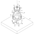
- FIG. 1 is a perspective view showing a device equipped with a coaxial connector connection structure according to an embodiment.
- FIG. 2 is a cross-sectional view taken along line II-II of FIG.
- FIG. 3 is a perspective view showing a connection structure of a coaxial connector.
- FIG. 4 is an exploded perspective view showing the same connection structure.
- FIG. 5 is an enlarged cross-sectional view of FIG.
- FIG. 6 is a perspective view showing the tip of the second coaxial connector.
- FIG. 7 is a partial cross-sectional view showing a connection structure of a coaxial connector according to a modified example.
- FIG. 8 is a partial cross-sectional view showing a connection structure of a coaxial connector according to another modified example.
- connection structure of the coaxial connector disclosed herein is as follows:
- a coaxial connector connection structure in which a first coaxial connector and a second coaxial connector are connected the first coaxial connector includes a first inner conductor and a first outer conductor surrounding the outer periphery of the first inner conductor
- the second coaxial connector includes a second inner conductor and a second outer conductor surrounding the outer periphery of the second inner conductor
- the first inner conductor has an inner elastic piece that can elastically deform in the inward and outward directions
- the second inner conductor has an inner connecting tube portion
- the first inner conductor is inserted and connected to the second inner conductor with the inner elastic piece in elastic contact with the inner periphery of the inner connecting tube portion.
- the first inner conductor is inserted and connected to the second inner conductor with the inner elastic piece in elastic contact with the inner peripheral surface of the inner connection tube portion, so the external shape of the connection between the first inner conductor and the second inner conductor is less likely to change in the connection direction between the first coaxial connector and the second coaxial connector. This makes it easier to design the shape to obtain the desired communication performance, and provides a coaxial connector connection structure that makes it easier to improve communication performance.
- the first inner conductor may have a plurality of the inner elastic pieces, the plurality of inner elastic pieces may be arranged at intervals along the circumferential direction of the inner connection tube portion, and a gap may be formed between adjacent inner elastic pieces among the plurality of inner elastic pieces to prevent contact between the adjacent inner elastic pieces when the plurality of inner elastic pieces are in elastic contact with the inner peripheral surface of the inner connection tube portion.
- the first inner conductor can be smoothly inserted and connected to the second inner conductor.
- the inner connection tube portion has a recess that is recessed from the tip side of the inner connection tube portion toward the base end side, and the circumferential width of the recess may be smaller than the circumferential width of the inner elastic piece.
- the contact pressure of the inner elastic piece against the inner connection tube portion may be set to a value that maintains the initial shape of the inner connection tube portion when the inner elastic piece is in elastic contact with the inner connection tube portion.
- the first inner conductor may be a pressed metal plate.
- the outer shape of the inner elastic piece will easily be formed with an uneven shape. Even in this case, by arranging the inner connection tube portion on the outside of the inner elastic piece, the outer shape of the connection between the first inner conductor and the second inner conductor will be less likely to change in the connection direction of the first coaxial connector and the second coaxial connector. This makes it easier to design the shape to obtain the desired communication performance, even if the first inner conductor is a pressed product of metal plate, and it is possible to provide a connection structure for a coaxial connector that is likely to improve communication performance.
- the second inner conductor has an opposite side connection tube portion, the outer diameter of the opposite side connection tube portion is smaller than the outer diameter of the inner connection tube portion, and between the inner connection tube portion and the opposite side connection tube portion there is a tapered portion whose outer diameter gradually decreases from the inner connection tube portion toward the opposite side connection tube portion, and a slit may be formed along the circumferential direction of the inner connection tube portion at the boundary between the inner connection tube portion and the tapered portion.
- a slit is formed along the circumferential direction of the inner connecting tube portion at the boundary between the inner connecting tube portion and the tapered portion, making it easy to form a tapered portion that gradually narrows relative to the inner connecting tube portion.
- connection structure for a coaxial connector according to any one of (1) to (6), wherein the inner elastic piece includes an inner inclined portion that inclines outward from the base end to the tip end of the inner elastic piece, and at least a portion of the inner inclined portion may be inclined toward the central axis of the inner connecting tube portion as it moves away from the tip end of the inner connecting tube portion, outside the tip opening of the inner connecting tube portion, in the connection direction between the first coaxial connector and the second coaxial connector.
- connection structure of any one of the coaxial connectors described in (1) to (7) in which one of the first outer conductor and the second outer conductor has an outer elastic piece that is elastically deformable in the inward and outward directions, and the other of the first outer conductor and the second outer conductor has an outer connection tube portion, and the other of the first outer conductor and the second outer conductor may be inserted and connected to the one of the first outer conductor and the second outer conductor with the outer elastic piece in elastic contact with the outer peripheral surface of the outer connection tube portion.
- the other of the first and second outer conductors having the outer connection tube portion is inserted and connected to the other of the first and second outer conductors having the outer elastic piece, so that the outer connection tube portion is positioned on the inside.
- the inner shape of the connection between the first and second outer conductors is less likely to change in the connection direction between the first and second coaxial connectors. This makes it less likely that the distance between the inner and outer conductors will change in the connection direction, making it easier to design the shape to obtain the desired communication performance.
- This makes it possible to provide a connection structure for a coaxial connector that easily improves communication performance.
- the first outer conductor may have the outer elastic piece
- the second outer conductor may have the outer connection tube portion
- the second outer conductor may be inserted and connected to the first outer conductor with the outer elastic piece in elastic contact with the outer peripheral surface of the outer connection tube portion.
- the first coaxial connector has both an inner connection tube portion and an outer connection tube portion, the inner connection tube portion and the outer connection tube portion are more likely to be kept coaxial, making it easier to obtain good communication performance.
- connection structure of any one of coaxial connectors (1) to (7) in which the first outer conductor has an internal contact outer elastic piece that can elastically deform in the inward and outward directions, the second outer conductor has an outer connection tube portion, the first outer conductor is inserted and connected to the second outer conductor with the internal contact outer elastic piece in elastic contact with the inner peripheral surface of the outer connection tube portion, and in the connection direction between the first coaxial connector and the second coaxial connector, the contact position of the internal contact outer elastic piece with respect to the inner peripheral surface of the outer connection tube portion may be located closer to the tip of the outer connection tube portion than the contact position of the internal elastic piece with respect to the inner peripheral surface of the inner connection tube portion.
- the first inner conductor is inserted and connected to the second inner conductor, it is assumed that the outer shape of the connection between the first inner conductor and the second inner conductor becomes thinner at the tip side of the inner connection tube. Therefore, the first outer conductor is inserted and connected to the second outer conductor while the inner contact outer elastic piece is in elastic contact with the inner peripheral surface of the outer connection tube.
- the inner shape of the connection between the first outer conductor and the second outer conductor can become thinner according to the change in shape of the connection between the first inner conductor and the second inner conductor.
- the contact position of the inner contact outer elastic piece with the inner peripheral surface of the inner connection tube is located closer to the tip side of the outer connection tube than the contact position of the inner elastic piece with the inner peripheral surface of the inner connection tube.
- the inner inclined part of the inner elastic piece and the inner contact outer inclined part of the inner contact outer elastic piece are inclined toward the central axis. This makes it easier to keep the distance between the inner elastic piece and the inner contact outer elastic piece constant, making it easier to design the shape to achieve the desired communication performance.
- connection structure of the coaxial connector of the present disclosure will be described below with reference to the drawings. Note that the present disclosure is not limited to these examples, but is defined by the claims, and is intended to include all modifications within the meaning and scope of the claims.
- FIG. 1 is a perspective view showing a device 10 equipped with a coaxial connector connection structure 28.
- Fig. 2 is a cross-sectional view taken along line II-II in Fig. 1.
- the device 10 is, for example, a camera device.
- the camera device is, for example, a device mounted on a vehicle.
- the device 10 does not have to be a camera device.
- the device 10 comprises a case 12, an electrical component 20, and a coaxial connector for external connection 30.
- the electrical component 20 is housed inside the case 12.
- the coaxial connector for external connection 30 is a connector for connecting the electrical component 20 to an external electrical component.
- the coaxial connector for external connection 30 is a connector to which a cable connected to an external electrical component is connected.
- the case 12 comprises a first case 13 and a second case 14.
- the first case 13 and the second case 14 are formed, for example, from resin.
- the first case 13 and the second case 14 are combined to form the rectangular box-shaped case 12 that houses the electrical components 20. If the device 10 is a camera device, it is assumed that the first case 13 has a lens or window for capturing images, and the second case 14 has a coaxial connector 30 for external connection.
- a retaining tube portion 16 protrudes from the bottom 15 of the case 12.
- the retaining tube portion 16 is cylindrical and protrudes outward from the center of the bottom 15.
- the inner opening of the retaining tube portion 16 opens into the second case 14, and the outer opening of the retaining tube portion 16 opens to the outside of the second case 14.
- a retaining partition portion 17 is formed in the middle of the retaining tube portion 16 in the direction along the central axis X.
- the retaining partition portion 17 is formed in the middle of the retaining tube portion 16 in the direction along the central axis X, near the inner opening.
- the retaining partition portion 17 separates the space of the retaining tube portion 16 on the inner opening side from the space of the outer opening side.
- a retaining hole 17h is formed in the retaining partition portion 17, and the external connection coaxial connector 30 is inserted and held in the retaining hole 17h.
- the coaxial connector 30 for external connection comprises an inner conductor 32 for external connection, a dielectric 34 for external connection, and an outer conductor 36 for external connection.
- the external connection inner conductor 32 is formed in a long, thin rod shape and is made of a conductive material such as metal.
- the external connection inner conductor 32 is an example of a pin-shaped opposite side inner conductor that is inserted and connected to the second inner conductor 80 described below.
- the external connection dielectric 34 is formed of an insulator such as resin and surrounds the external connection inner conductor 32.
- the external connection outer conductor 36 is formed of a conductive material such as metal.
- the external connection outer conductor 36 is formed in a cylindrical shape that surrounds the external connection dielectric 34.
- the external connection outer conductor 36 is an example of an opposite side outer conductor to which the second outer conductor 90 is connected.
- the electrical component 20 is, for example, a mounting board on which electronic components are mounted.
- the electrical component 20 is assumed to be a circuit board 21 and an image sensor 22 mounted on the circuit board 21.
- the image sensor 22 faces an image capturing lens or window in the first case 13, and captures the outside scenery by rotating the lens or window.
- the side of the first case 13 to which the image sensor 22 faces may be referred to as the front side, and the opposite side, the second case 14 side, may be referred to as the rear side.
- a coaxial connector connection structure 28 is incorporated into the device 10.
- the coaxial connector connection structure 28 is a connection structure between a first coaxial connector 40 and a second coaxial connector 70.
- the first coaxial connector 40 is provided on the surface of the circuit board 21 opposite the imaging element 22.
- the first coaxial connector 40 is an example of a board-side coaxial connector that is fixed to the circuit board 21.
- the first coaxial connector 40 includes a first inner conductor 50, a first outer conductor 60 that surrounds the outer periphery of the first inner conductor 50, and a first dielectric 42 that is located between the first inner conductor 50 and the first outer conductor 60.
- the first dielectric 42 surrounds the first inner conductor 50.
- the first dielectric 42 is formed of an insulator.
- the first outer conductor 60 surrounds the first dielectric 42.
- the base end of the first inner conductor 50 and the base end of the first outer conductor 60 are fixed to the circuit board 21 by soldering or the like.
- the first inner conductor 50 and the first outer conductor 60 are electrically connected to the circuit of the circuit board 21 and are fixed in a state protruding from the circuit board 21.
- the first coaxial connector 40 protrudes from the circuit board 21 toward the coaxial connector 30 for external connection.
- the first dielectric 42 may be omitted.
- the second coaxial connector 70 is connected to the first coaxial connector 40.
- the second coaxial connector 70 includes a second inner conductor 80, a second outer conductor 90 surrounding the outer periphery of the second inner conductor 80, and a second dielectric 72 located between the second inner conductor 80 and the second outer conductor 90.
- the second dielectric 72 surrounds the periphery of the second inner conductor 80.
- the second dielectric 72 is made of an insulator.
- the second outer conductor 90 surrounds the periphery of the second dielectric 72.
- the second coaxial connector 70 is connected to the first coaxial connector 40 with the first inner conductor 50 inserted and connected to the second inner conductor 80 and the second outer conductor 90 inserted and connected to the first outer conductor 60.
- the second coaxial connector 70 protrudes further from the first coaxial connector 40 toward the coaxial connector 30 for external connection.
- the second coaxial connector 70 relays and connects the first coaxial connector 40 and the coaxial connector 30 for external connection.
- the second coaxial connector 70 is connected to the first coaxial connector 40 and the coaxial connector 30 for external connection in such a way that its posture can be changed.
- the external coaxial connector 30 may be understood to be the third coaxial connector
- the second coaxial connector 70 may be understood to be an intermediate coaxial connector that intermediately connects the first coaxial connector 40 and the third coaxial connector.
- the coaxial connector 30 for external connection is provided on the second case 14 side, i.e., the rear side of the case 12. Inside the case 12, the second coaxial connector 70 is connected to the coaxial connector 30 for external connection.
- the external electrical component to which the cable is connected is electrically connected to the electrical component 20 inside the case 12.
- the circuit board 21 is supported at a fixed position within the case 12.
- the position of the first coaxial connector 40 relative to the coaxial connector 30 for external connection is set to a fixed position.
- the position of the first coaxial connector 40 relative to the coaxial connector 30 for external connection may deviate from the designed position.
- the variation in distance can be absorbed by adjusting the insertion amount of the second coaxial connector 70 relative to the first coaxial connector 40. Also, even if the external connection coaxial connector 30 is displaced from a position coaxially facing the first coaxial connector 40, the second coaxial connector 70 is tilted relative to the first coaxial connector 40 and the external connection coaxial connector 30, thereby absorbing the positional deviation.
- Fig. 3 is a perspective view showing the coaxial connector connection structure 28.
- Fig. 4 is an exploded perspective view showing the same connection structure.
- Fig. 5 is an enlarged cross-sectional view of Fig. 3.
- Fig. 6 is a perspective view showing the tip of the second coaxial connector 70. In Fig. 6, the elastic pieces 56, 66 are partially shown.
- the first coaxial connector 40 includes the first inner conductor 50 , the first outer conductor 60 , and the first dielectric material 42 .
- the first inner conductor 50 is an elongated conductive member.
- the first inner conductor 50 may be a pressed metal plate.
- a pressed metal plate is an object formed by punching and bending a metal plate by press processing, and has a shape in which a metal plate of substantially uniform thickness is bent into a predetermined shape.
- the first inner conductor may also be formed by cutting a metal material.
- the first inner conductor 50 includes a base end inner tube portion 52 and an inner elastic piece 56.
- the base end side inner tube portion 52 is formed in a tubular shape, more specifically, in a cylindrical shape.
- the base end portion of the first inner conductor 50 is housed and held in the first dielectric 42.
- the tip end is the end to which the second coaxial connector 70 is connected, and the base end is the end opposite the tip end, in this case the end facing the circuit board 21.
- a positioning piece 53 is formed so as to protrude outward from a portion of the circumference at the base end of the base-side inner tube portion 52.
- the positioning piece 53 is a plate-shaped portion that follows the central axis of the base-side inner tube portion 52, and in this embodiment is a rectangular plate-shaped portion.
- the positioning piece 53 is configured with two overlapping plate-shaped portions.
- the base-side inner tube portion 52 is formed by pressing the plate-shaped portions into a tube.
- a plate-shaped portion protrudes outward from each of two adjacent edges at the joint of the tube, and the positioning piece 53 is formed by the overlap of the two plate-shaped portions.
- the protruding end 53e of the positioning piece 53 is formed with a slip-out prevention protrusion 53p that hooks onto the bottom of the positioning groove 44 of the first dielectric 42.
- the slip-out prevention protrusion 53p is formed in a shape that hooks onto the bottom of the positioning groove 44 so that the base end side inner tube portion 52 is less likely to slip out toward the tip side of the first dielectric 42.
- the base end side inner cylinder portion 52 may be formed with a locking piece 52a that hooks onto the inner peripheral surface of the first dielectric 42 when pressed into the first dielectric 42.
- a protruding piece 52b that extends along the main surface of the circuit board 21 and is used for soldering may be provided at the base end of the base end side inner cylinder portion 52.
- An inner elastic piece 56 protrudes from the tip of the base-end inner tube portion 52.
- the inner elastic piece 56 is formed so that it can elastically deform in the inward and outward directions of the first inner conductor 50.
- multiple (here, three) inner elastic pieces 56 are arranged at intervals in the circumferential direction from the tip of the base-end inner tube portion 52.
- the multiple inner elastic pieces 56 are positioned at equal intervals around the central axis X of the base-end inner tube portion 52.
- the inner elastic piece 56 includes an inner inclined portion 56a that inclines outward from the tip of the base-end inner tube portion 52, and a curved portion 56b that is connected to the tip of the inner inclined portion 56a and has an outwardly convex curved shape.
- the inner inclined portion 56a elastically deforms inward, while the outward apex of the curved portion 56b is elastically pressed against the inner peripheral surface of the second inner conductor 80. This keeps the first inner conductor 50 electrically connected to the second inner conductor 80.
- the outward apex of the curved portion 56b comes into contact with the inner peripheral surface of the second inner conductor 80, allowing the inner elastic piece 56 to stably come into contact with the second inner conductor 80 in a limited, small area. If the inner elastic piece 56 is formed by pressing a metal plate, the surface of the curved portion 56b opposite the outward apex will be a concave surface.
- the multiple inner elastic pieces 56 are inserted into the second inner conductor 80, the multiple inner elastic pieces 56 are displaced toward the center axis X of the second inner conductor 80. As a result, the intervals between the multiple inner elastic pieces 56 in the circumferential direction of the base end inner tube portion 52 become smaller. Between the multiple inner elastic pieces 56 adjacent to each other in the circumferential direction, a gap Ws is formed that prevents contact between adjacent inner elastic pieces 56 when the multiple inner elastic pieces 56 are in elastic contact with the inner circumferential surface of the inner connecting tube portion 82 of the second inner conductor 80 (see FIG. 4).
- the gap Ws is set to a size that can prevent interference between the multiple inner elastic pieces 56 depending on the width and bending shape of the multiple inner elastic pieces 56, the inner diameter of the inner connecting tube portion 82, etc.
- the contact pressure of the inner elastic piece 56 against the inner connecting tube portion 82 is preferably set to a magnitude that maintains the initial shape of the inner connecting tube portion 82 when the inner elastic piece 56 is in elastic contact with the inner connecting tube portion 82.
- the initial shape of the inner connecting tube portion 82 is the shape before the multiple inner elastic pieces 56 are inserted into the inner connecting tube portion 82.
- the contact pressure of the inner elastic piece 56 is preferably set to a magnitude that suppresses deformation of the inner connecting tube portion 82.
- the contact pressure of the inner elastic piece 56 against the inner connecting tube portion 82 is the force with which the inner elastic piece 56 presses the inner connecting tube portion 82 toward the outer periphery.
- the multiple inner elastic pieces 56 are in elastic contact with the inner peripheral surface of the inner connecting tube portion 82, a force is applied to the inner connecting tube portion 82 that tends to spread it toward the outer periphery.
- the multiple inner elastic pieces 56 should be in elastic contact with the inner peripheral surface of the inner connecting tube portion 82 with a force that does not spread the inner connecting tube portion 82 toward the outer periphery.
- the force with which the inner elastic piece 56 presses the inner connecting tube portion 82 can be adjusted by changing the width, thickness, material, thickness, material, etc. of the inner elastic piece 56, the plating layer, etc.
- the number of inner elastic pieces may be two or four or more.
- the first dielectric 42 is formed into a disk shape from resin or the like.
- the maximum thickness dimension of the first dielectric 42 is smaller than the length dimension of the base end side inner tube portion 52.
- the first dielectric 42 is, for example, a molded resin part.
- an insertion hole 43 is formed into which the base end of the first inner conductor 50, more specifically the base end of the base end side inner tube portion 52, is inserted.
- a positioning groove 44 is formed into which a positioning piece 53 is fitted. The positioning groove 44 is recessed from a portion of the circumference of the insertion hole 43 toward the outer periphery and is formed as a groove extending along the central axis X.
- the base end side inner tube portion 52 is inserted into the insertion hole 43, so that the first inner conductor 50 is inserted and held in the first dielectric 42.
- the base end side inner tube portion 52 is press-fitted and held in the insertion hole 43.
- the press-fit structure makes it easier to hold the first inner conductor firmly against the first dielectric. If the first inner conductor 50 is a pressed product of a metal plate, a positioning piece 53 is fitted into the positioning groove 44 to increase the holding strength. The inner surface of the positioning groove 44 clamps the positioning piece 53, making it easier for the first dielectric 42 to hold the first inner conductor 50 firmly. If the first inner conductor 50 is a pressed product of a metal plate, the first inner conductor 50 can be manufactured at low cost.
- the anti-slip protrusion 53p of the positioning piece 53 hooks into the bottom of the positioning groove 44, making it difficult for the first inner conductor 50 to come out of the first dielectric 42, and the first inner conductor 50 is held more firmly.
- a retaining annular protrusion 45 that protrudes annularly toward the tip side of the first inner conductor 50 is formed in the portion of the first dielectric 42 that surrounds the insertion hole 43.
- the retaining annular protrusion 45 holds the base end side inner tube portion 52, so that the first inner conductor 50 is held more firmly and the first inner conductor 50 is less likely to tilt relative to the first dielectric 42.
- the outer peripheral surface of the first dielectric 42 is formed in a short cylindrical peripheral surface shape that can be inserted into the inner peripheral portion of the first outer conductor 60.
- An outer peripheral annular protrusion 46 that protrudes in an annular shape toward the tip side of the first inner conductor 50 is formed on the outer peripheral portion of the first dielectric 42 on the first outer conductor 60 side.
- the outer peripheral surface of the first dielectric 42 is formed wide in the direction of the central axis X by the outer peripheral annular protrusion 46. Therefore, the outer peripheral surface of the first dielectric 42 can face the inner peripheral surface of the first outer conductor 60 over a wide area.
- the first outer conductor 60 is made of a conductive material such as metal, and surrounds the first dielectric 42. Therefore, the first dielectric 42 is a cylindrical member interposed between the first inner conductor 50 and the first outer conductor 60.
- the first outer conductor 60 is formed, for example, by pressing a metal plate.
- the first outer conductor 60 includes a base end outer tube portion 62 and an outer elastic piece 66 that protrudes from the tip of the base end outer tube portion 62.
- the base end outer tube portion 62 is formed in a tubular shape, more specifically, a cylindrical shape, in which the first dielectric 42 can be placed.
- the first dielectric 42 is housed and held in the base end portion of the base end outer tube portion 62.
- the base end outer tube portion 62 may be formed with a locking piece 62a that hooks onto the outer peripheral surface of the first dielectric 42 when the first dielectric 42 is pressed in.
- An outer elastic piece 66 protrudes from the tip of the base-side outer tube portion 62.
- multiple (here, eight) outer elastic pieces 66 extend from the tip of the base-side outer tube portion 62 at intervals in the circumferential direction.
- the multiple outer elastic pieces 66 are positioned at equal intervals around the central axis X of the base-side outer tube portion 62.
- the outer elastic piece 66 includes an outer inclined portion 66a that inclines inward from the tip of the base-end outer tube portion 62, and a curved portion 66b that is connected to the tip of the outer inclined portion 66a and has an inwardly convex curved shape.
- the outer inclined portion 66a elastically deforms outward, while the inward apex of the curved portion 66b is elastically pressed against the outer peripheral surface of the second outer conductor 90. This keeps the first outer conductor 60 electrically connected to the second outer conductor 90.
- the inward apex of the curved portion 66b comes into contact with the outer peripheral surface of the second outer conductor 90, allowing the outer elastic piece 66 to stably come into contact with the second outer conductor 90 in a limited, small area. If the outer elastic piece 66 is formed by pressing a metal plate, the surface of the curved portion 66b opposite the inward apex becomes a concave surface.
- the number of outer elastic pieces may be seven or less, or nine or more.
- the length dimension of the base end side outer tube portion 62 is greater than the thickness dimension of the first dielectric 42. In this embodiment, the length dimension of the base end side outer tube portion 62 is greater than the length dimension of the first inner conductor 50. Furthermore, the base end of the outer elastic piece 66 is located farther away from the first dielectric 42 than the base end of the inner elastic piece 56. Furthermore, the tip of the outer elastic piece 66 is located farther away from the first dielectric 42 than the tip of the inner elastic piece 56. However, the curved portions 56b, 66b may contact the second inner conductor 80 or the second outer conductor 90 at the same position in the central axis X.
- the first coaxial connector 40 may be surrounded by a cylindrical connector holder 41.
- the connector holder 41 is a member formed of resin or the like, and serves to surround the first coaxial connector 40 from all sides and prevent it from coming into contact with other members.
- the second coaxial connector 70 includes the second inner conductor 80 , the second outer conductor 90 , and the second dielectric 72 .
- the second inner conductor 80 is an elongated conductive member.
- the second inner conductor 80 is formed by pressing a metal plate. More specifically, the second inner conductor 80 includes an inner connection tube portion 82. In this embodiment, the second inner conductor 80 further includes an opposite side connection tube portion 86.
- the second inner conductor may be a machined product.
- the inner connection tube portion 82 is formed in a tube shape, more specifically, a cylindrical shape.
- the open end of the inner connection tube portion 82 faces the first coaxial connector 40.
- the inner connection tube portion 82 is the portion into which the multiple inner elastic pieces 56 of the first inner conductor 50 are inserted and connected.
- the inner connecting tube portion 82 is a thin tube that is elongated along the central axis X.
- the inner diameter of the inner connecting tube portion 82 is smaller than the outer diameter of an imaginary circle that connects the tops of the multiple inner elastic pieces 56.
- the multiple inner elastic pieces 56 can elastically contact the inner peripheral surface of the inner connecting tube portion 82 while elastically deforming inward.
- the opposite side connection tube portion 86 is located on the opposite side of the first coaxial connector 40 with respect to the inner connection tube portion 82.
- the outer diameter of the opposite side connection tube portion 86 is smaller than the outer diameter of the inner connection tube portion 82.
- the opposite side connecting tube portion 86 is connected to the inner connecting tube portion 82 via a tapered portion 81.
- the tapered portion 81 is a tapered portion whose outer diameter gradually decreases from the inner connecting tube portion 82 toward the opposite side connecting tube portion 86.
- the opposite side connecting tube portion may be connected to the inner connecting tube portion via a step portion.
- a slit 81S1 is formed along the circumferential direction of the inner connecting cylinder 82 at the boundary between the inner connecting cylinder 82 and the tapered portion 81 (see FIG. 4).
- the slit 81S1 is formed to extend over an area of about 1/3 to 2/3, and preferably about half, of the entire circumference of the inner connecting cylinder 82.
- a seam is formed along the central axis X in a portion of the circumference of the inner connection tube portion 82.
- the slit 81S1 may extend to both sides of the seam. In this case, the metal plate can be easily bent near the seam, making it easier to press work the second inner conductor 80.
- An additional gap 81S2 may be provided at the joint in the tapered portion 81.
- the gap 81S2 is formed as a triangular gap that opens from the slit 81S1 toward the tapered portion 81.
- the gap 81S2 makes it easy to round the tapered portion 81 while suppressing interference at the joint, and makes it easy to press the second inner conductor 80.
- the slit 81S1 and gap 81S2 may be omitted.
- the opposite side connection tube portion 86 may have an elastic piece 87 that protrudes toward the tip side.
- the elastic piece 87 is configured to be elastically deformable in the inward and outward directions.
- the external connection inner conductor 32 is inserted between the two elastic pieces 87 from the tip side of the two elastic pieces 87. When the external connection inner conductor 32 is sandwiched between the two elastic pieces 87, the second inner conductor 80 is connected to the external connection inner conductor 32.
- the opposite side connecting tube portion 86 may be formed with a partial locking piece 86a that can be locked to the second dielectric 72.
- the second dielectric 72 is made of resin or the like.
- the second dielectric 72 is, for example, a molded resin part.
- the second dielectric 72 is formed in a tubular shape capable of accommodating at least a portion of the second inner conductor 80.
- the second dielectric 72 is formed in a cylindrical shape.
- the opposite side connecting tube portion 86 is accommodated within the second dielectric 72.
- the internal space of the opposite side connecting tube portion 86 is formed large enough to hold the base end of the opposite side connecting tube portion 86 in a pressed-in state and to allow elastic deformation of the elastic piece 87 in the inward and outward directions.
- One end of the second dielectric 72 contacts the tapered portion 81, thereby positioning the second dielectric 72 relative to the second inner conductor 80.
- the inner connecting tube portion 82 extends further toward the first coaxial connector 40 than the second dielectric 72.
- the second dielectric 72 may surround the inner connecting tube portion 82.
- a dielectric other than the second dielectric 72 may surround the inner connecting tube portion 82.
- the second outer conductor 90 is disposed on the outer periphery of the second dielectric 72.
- the second outer conductor 90 is formed from a conductive material such as metal, and surrounds the second dielectric 72.
- the second outer conductor 90 is formed, for example, by pressing a metal plate.
- the second outer conductor 90 has an outer connection tube portion 92 and an opposite outer connection tube portion 96.
- the outer connection tube portion 92 is formed in a tube shape, more specifically, in a cylindrical shape.
- the open end of the outer connection tube portion 92 faces the first coaxial connector 40.
- the outer connection tube portion 92 is the portion that is connected to the first outer conductor 60.
- the outer connection tube portion 92 is positioned on the outer periphery side of the inner connection tube portion 82 with a gap therebetween.
- the outer diameter of the outer connection tube portion 92 is larger than the outer diameter of an imaginary circle connecting the tops of the multiple outer elastic pieces 66.
- the multiple outer elastic pieces 66 can elastically contact the outer periphery surface of the outer connection tube portion 92 while elastically deforming outward.
- the opposite side external connection tube portion 96 is located on the opposite side of the first coaxial connector 40 with respect to the outer connection tube portion 92.
- the opposite side external connection tube portion 96 is thinner than the outer connection tube portion 92.
- the opposite side external connection tube portion 96 is connected to the outer connection tube portion 92 via a tapered portion 91.
- the tapered portion 91 is a tapered portion that gradually becomes thinner from the outer connection tube portion 92 toward the opposite side external connection tube portion 96.
- the opposite side connection tube portion may be connected to the outer connection tube portion via a step portion.
- the opposite external connection tube portion 96 may have an elastic piece 97 that protrudes toward the tip side.
- the elastic piece 97 is configured to be elastically deformable in the inward and outward directions.
- the external connection outer conductor 36 is fitted onto the outer periphery of the multiple elastic pieces 97 from the tip side of the multiple elastic pieces 97.
- the multiple elastic pieces 97 are elastically pressed against the inner peripheral surface of the external connection outer conductor 36, thereby connecting the second outer conductor 90 to the external connection outer conductor 36.
- the opposite external connection tube portion 96 may be formed with a partial locking piece 96a that can be locked to the second dielectric 72.
- the inner connecting tube portion 82 and the outer connecting tube portion 92 may be formed with recesses 83a, 83b, 83c, 93a, 93b, 93c that are recessed toward the base end when viewed from the tip end (see Figure 6).
- the recesses 83a, 83b, 83c, 93a, 93b, and 93c may be recesses for facilitating processing such as bending and carrier cutting during press processing.
- the recess 83b may be a slit-shaped recess for easily processing the tip of the inner connecting tube portion 82 into an outward tapered shape.
- the recesses 83c and 93c may be thin recesses formed by the respective seams of the inner connecting tube portion 82 and the outer connecting tube portion 92.
- the width of the recesses 83a, 83b, and 83c (for example, the width S1 of the recess 83b) is preferably smaller than the width W1 of the inner elastic piece 56. This allows the inner elastic piece 56 to move smoothly toward the inner surface of the inner connecting tube portion 82 without fitting into the recesses 83a, 83b, and 83c.
- the width of the recesses 93a, 93b, and 93c is smaller than the width of the outer elastic piece 66. This allows the outer elastic piece 66 to move smoothly toward the outer peripheral surface of the outer connecting tube portion 92 without fitting into the recesses 93a, 93b, and 93c.
- the first inner conductor 50 is inserted and connected to the second inner conductor 80 with the multiple inner elastic pieces 56 in elastic contact with the inner surface of the inner connection tube portion 82.
- the second inner conductor 80 is inserted and connected to the first inner conductor 50 with the multiple outer elastic pieces 66 in elastic contact with the outer peripheral surface of the outer connection tube portion 92.
- the first inner conductor 50 having the inner elastic piece 56 Focusing on the connection between the first inner conductor 50 and the second inner conductor 80, the first inner conductor 50 having the inner elastic piece 56 is located inside the inner connecting tube portion 82. Therefore, the outer shape of the connection between the first inner conductor 50 and the second inner conductor 80 reflects the outer shape of the inner connecting tube portion 82, in which the same-diameter portions are continuous. In other words, regardless of the curved shape of the inner elastic piece 56, the outer shape of the connection between the first inner conductor 50 and the second inner conductor 80 is a shape in which the same-diameter portions are continuous.
- the inner shape of the connection between the first outer conductor 60 and the second outer conductor 90 reflects the outer shape of the outer connection tube portion 92, in which the same-diameter portions are continuous.
- the inner shape of the connection between the first outer conductor 60 and the second outer conductor 90 is a shape in which the same-diameter portions are continuous.
- connection structure 28 of the coaxial connector For example, it becomes easy to design the connection structure 28 such that the characteristic impedance is set to 50 ⁇ , assuming a constant distance between the inner and outer conductors.
- the first inner conductor 50 is inserted and connected to the second inner conductor 80 with the inner elastic piece 56 in elastic contact with the inner circumferential surface of the inner elastic piece 56, so that the outer shape of the inner conductor, which is the connection between the first inner conductor 50 and the second inner conductor 80, is less likely to change in the connection direction of the coaxial connectors 40, 70.
- it is easy to design the shape to obtain the desired communication performance assuming that most parts of the inner conductor have a constant outer diameter, and it is possible to provide a coaxial connector connection structure 28 that makes it easy to improve communication performance.
- connection amount between the first coaxial connector 40 and the second coaxial connector 70 varies, a constant conductor distance is maintained between the inner connection tube portion 82 and the outer connection tube portion 92. This makes it easier to maintain constant communication performance.
- connection body including the first inner conductor 50 and the second inner conductor 80 and the connection body including the first outer conductor 60 and the second outer conductor 90 may be made on the assumption that air exists between them, or that a tangible dielectric material such as a resin exists between them.
- the first inner conductor 50 can be smoothly inserted and connected to the second inner conductor 80.
- the inner connecting tube portion 82 has recesses 83a, 83b, and 83c that are recessed when viewed from the tip side, and the width (e.g., width S1) of the recesses 83a, 83b, and 83c is smaller than the width W1 of the inner elastic piece 56, the inner elastic piece 56 will be smoothly inserted into the inner connecting tube portion 82 without fitting into the recesses 83a, 83b, and 83c.
- the contact pressure of the inner elastic piece 56 against the inner connecting tube portion 82 is set to a value that maintains the initial shape of the inner connecting tube portion 82, the first inner conductor 50 and the second inner conductor 80 can be connected well without causing poor contact due to deformation of the inner connecting tube portion 82.
- the uneven shape for contacting the inner connecting tube portion 82 is reflected on both sides of the inner elastic piece 56. For this reason, it is expected that the outer shape of the inner elastic piece 56 will easily be formed with an uneven shape. Even in this case, by arranging the inner connecting tube portion 82 on the outside of the inner elastic piece 56, the outer shape of the connection between the first inner conductor 50 and the second inner conductor 80 is less likely to change in the connection direction. As a result, even if the first inner conductor 50 is a pressed product of a metal plate, it is easier to design the shape to obtain the desired communication performance, and a coaxial connector connection structure 28 that is easy to improve communication performance can be provided.
- a slit 81S1 is formed along the circumferential direction of the inner connecting tube portion 82 at the boundary between the inner connecting tube portion 82 and the tapered portion 81, making it easy to form the tapered portion 81 that gradually narrows relative to the inner connecting tube portion 82.
- impedance can be easily adjusted by adjusting the width, length, etc. of the slit 81S1.
- the second outer conductor 90 is inserted and connected to the first outer conductor 60 with the outer elastic piece 66 in elastic contact with the outer peripheral surface of the outer connection tube portion 92. This makes it difficult for the inner shape of the connection between the first outer conductor 60 and the second outer conductor 90 to change in the connection direction. This makes it even more difficult for the distance between the inner and outer conductors to change in the connection direction, making it easier to design the shape to obtain the desired communication performance. This makes it possible to provide a coaxial connector connection structure 28 that easily improves communication performance.
- the second coaxial connector 70 has an inner connection tube portion 82 and an outer connection tube portion 92.
- the inner connection tube portion 82 and the outer connection tube portion 92 are easily maintained coaxially, making it easier to obtain good communication performance.
- At least a portion of the inner inclined portion 56a may be inclined toward the central axis X in the connection direction, outside the tip opening of the inner connecting cylinder portion 82, as it moves away from the tip of the inner connecting cylinder portion 82.
- At least a portion of the inner inclined portion 56a is inclined outward from the tip opening of the inner connecting tube portion 82 (see Figure 5).
- a portion of the inner inclined portion 56a close to the tip is located at the opening of the inner connecting tube portion 82, as in the modified example shown in FIG. 7.
- the above configuration can be realized by shortening the base end side inner tube portion 152 of the first inner conductor 150 corresponding to the first inner conductor 50.
- the amount of recess (step) of the inner inclined portion 56a relative to the opening edge of the inner connecting tube portion 82 can be reduced at the portion protruding from the opening of the inner connecting tube portion 82.
- the outer shape of the connection between the first inner conductor 150 and the second inner conductor 80 can be gradually reduced from the opening edge of the inner connecting tube portion 82 toward the base end inner tube portion 52 in accordance with the inclination of the inner inclined portion 56a. This makes it easier to design the shape to obtain the desired communication performance, and provides a connection structure for a coaxial connector that facilitates good communication performance.
- the first outer conductor 160 corresponding to the first outer conductor 60 may have an internal contact outer elastic piece 166 that is elastically deformable in the inward and outward directions.
- the first outer conductor 160 may be inserted and connected to the second outer conductor 90 with this internal contact outer elastic piece 166 in elastic contact with the inner circumferential surface of the outer connection tube portion 92.
- the contact position P1 of the internal contact outer elastic piece 166 with the inner peripheral surface of the outer connecting tube portion 92 should be located closer to the tip of the outer connecting tube portion 92 than the contact position P2 of the inner elastic piece 56 with the inner peripheral surface of the inner connecting tube portion 82.
- the contact position P1 should be located closer to the tip of the outer connecting tube portion 92 than the tip opening of the inner connecting tube portion 82.
- the inner shape in the connection direction, in the portion where the outer shape narrows as it switches from the inner connection tube portion 82 to the inner elastic piece 56, the inner shape can be narrowed as it switches from the outer connection tube portion 92 to the inner contact outer elastic piece 166.
- the outer connection tube portion 92 surrounds the outer periphery of the contact position P2 of the inner elastic piece 56. Therefore, changes in the distance between the inner and outer conductors are suppressed even in the area further towards the tip side than the inner contact outer elastic piece 166. This makes it easier to design the shape to obtain the desired communication performance.
- the internal contact outer elastic piece 166 includes an internal contact outer inclined portion 166a that inclines outward from the base end of the internal contact outer elastic piece 166 toward the tip. At least a portion of this internal contact outer inclined portion 166a is outside the tip opening of the outer connecting tube portion 92 and inclined toward the central axis X in the connection direction as it moves away from the tip of the outer connecting tube portion 92.
- the inner inclined portion 56a of the inner elastic piece 56 and the inner contact outer inclined portion 166a of the inner contact outer elastic piece 166 are inclined to the same side toward the central axis X. This makes it easier to keep the distance between the inner elastic piece 56 and the inner contact outer elastic piece 166 constant, making it easier to design the shape to achieve the desired communication performance.
- the first coaxial connector 40 includes an inner elastic piece 56 and an outer elastic piece 66
- the second coaxial connector 70 includes an inner connecting tube portion 82 and an outer connecting tube portion 92
- the first coaxial connector may include an inner elastic piece and an outer connecting tube portion
- the second coaxial connector may include an inner connecting tube portion and an outer elastic piece.
- the board-side coaxial connector may have an inner connection tube portion and an outer connection tube portion
- the relay coaxial connector may have an inner elastic piece and an outer elastic piece
- the configuration according to the above embodiment may be applied to the connection between the relay coaxial connector and the external connection coaxial connector, and may be applied to the connection structure of other coaxial connectors, not limited to the above device.
Landscapes
- Coupling Device And Connection With Printed Circuit (AREA)
Priority Applications (1)
| Application Number | Priority Date | Filing Date | Title |
|---|---|---|---|
| CN202480037084.8A CN121285912A (zh) | 2023-06-07 | 2024-05-28 | 同轴连接器的连接结构 |
Applications Claiming Priority (2)
| Application Number | Priority Date | Filing Date | Title |
|---|---|---|---|
| JP2023093723A JP2024175752A (ja) | 2023-06-07 | 2023-06-07 | 同軸コネクタの接続構造 |
| JP2023-093723 | 2023-06-07 |
Publications (1)
| Publication Number | Publication Date |
|---|---|
| WO2024252978A1 true WO2024252978A1 (ja) | 2024-12-12 |
Family
ID=93795944
Family Applications (1)
| Application Number | Title | Priority Date | Filing Date |
|---|---|---|---|
| PCT/JP2024/019486 Ceased WO2024252978A1 (ja) | 2023-06-07 | 2024-05-28 | 同軸コネクタの接続構造 |
Country Status (3)
| Country | Link |
|---|---|
| JP (1) | JP2024175752A (https=) |
| CN (1) | CN121285912A (https=) |
| WO (1) | WO2024252978A1 (https=) |
Citations (3)
| Publication number | Priority date | Publication date | Assignee | Title |
|---|---|---|---|---|
| US6497579B1 (en) * | 1999-03-02 | 2002-12-24 | Huber+Suhner Ag | Coaxial connection with a tiltable adapter for a printed circuit board |
| JP2021077601A (ja) * | 2019-11-13 | 2021-05-20 | 株式会社オートネットワーク技術研究所 | コネクタ装置 |
| JP2021077637A (ja) * | 2019-11-08 | 2021-05-20 | ギガレーン カンパニー リミテッドGigalane Co., Ltd. | 関節運動範囲が制限されるコネクタ |
-
2023
- 2023-06-07 JP JP2023093723A patent/JP2024175752A/ja active Pending
-
2024
- 2024-05-28 WO PCT/JP2024/019486 patent/WO2024252978A1/ja not_active Ceased
- 2024-05-28 CN CN202480037084.8A patent/CN121285912A/zh active Pending
Patent Citations (3)
| Publication number | Priority date | Publication date | Assignee | Title |
|---|---|---|---|---|
| US6497579B1 (en) * | 1999-03-02 | 2002-12-24 | Huber+Suhner Ag | Coaxial connection with a tiltable adapter for a printed circuit board |
| JP2021077637A (ja) * | 2019-11-08 | 2021-05-20 | ギガレーン カンパニー リミテッドGigalane Co., Ltd. | 関節運動範囲が制限されるコネクタ |
| JP2021077601A (ja) * | 2019-11-13 | 2021-05-20 | 株式会社オートネットワーク技術研究所 | コネクタ装置 |
Also Published As
| Publication number | Publication date |
|---|---|
| JP2024175752A (ja) | 2024-12-19 |
| CN121285912A (zh) | 2026-01-06 |
Similar Documents
| Publication | Publication Date | Title |
|---|---|---|
| CN112290294B (zh) | 带浮动机构的同轴连接器 | |
| JP6183626B2 (ja) | フローティング機構付き同軸コネクタ | |
| JP7852420B2 (ja) | コネクタ | |
| JP2005294217A (ja) | 圧接型コンタクトおよびそれを用いた電気コネクタ | |
| WO2024252978A1 (ja) | 同軸コネクタの接続構造 | |
| JP7757876B2 (ja) | コネクタ | |
| JP2024175751A (ja) | 同軸コネクタおよび同軸コネクタの接続構造 | |
| WO2023106057A1 (ja) | 端子 | |
| WO2024253006A1 (ja) | 同軸コネクタの接続構造 | |
| JP6151517B2 (ja) | コネクタ | |
| WO2025009390A1 (ja) | コネクタ | |
| WO2025009369A1 (ja) | コネクタ | |
| WO2025009360A1 (ja) | コネクタ | |
| JP7779205B2 (ja) | 同軸コネクタ | |
| JP2025008371A (ja) | コネクタ | |
| CN120917631A (zh) | 同轴连接器 | |
| CN120453759A (zh) | 端子 | |
| WO2024241859A1 (ja) | 筒端子、同軸コネクタ及び筒端子の固定構造 | |
| CN119234361A (zh) | 同轴连接器 | |
| JP2024162065A (ja) | 端子および同軸コネクタ | |
| JP2000100523A (ja) | シールドコネクタ |
Legal Events
| Date | Code | Title | Description |
|---|---|---|---|
| 121 | Ep: the epo has been informed by wipo that ep was designated in this application |
Ref document number: 24819209 Country of ref document: EP Kind code of ref document: A1 |
|
| NENP | Non-entry into the national phase |
Ref country code: DE |