WO2024252898A1 - リザーバ、光ファイバの製造方法および光ファイバの製造装置 - Google Patents
リザーバ、光ファイバの製造方法および光ファイバの製造装置 Download PDFInfo
- Publication number
- WO2024252898A1 WO2024252898A1 PCT/JP2024/018367 JP2024018367W WO2024252898A1 WO 2024252898 A1 WO2024252898 A1 WO 2024252898A1 JP 2024018367 W JP2024018367 W JP 2024018367W WO 2024252898 A1 WO2024252898 A1 WO 2024252898A1
- Authority
- WO
- WIPO (PCT)
- Prior art keywords
- reservoir
- optical fiber
- ppm
- glass pipe
- glass
- Prior art date
- Legal status (The legal status is an assumption and is not a legal conclusion. Google has not performed a legal analysis and makes no representation as to the accuracy of the status listed.)
- Ceased
Links
Images



Classifications
-
- C—CHEMISTRY; METALLURGY
- C03—GLASS; MINERAL OR SLAG WOOL
- C03B—MANUFACTURE, SHAPING, OR SUPPLEMENTARY PROCESSES
- C03B37/00—Manufacture or treatment of flakes, fibres, or filaments from softened glass, minerals, or slags
- C03B37/01—Manufacture of glass fibres or filaments
- C03B37/012—Manufacture of preforms for drawing fibres or filaments
-
- C—CHEMISTRY; METALLURGY
- C03—GLASS; MINERAL OR SLAG WOOL
- C03C—CHEMICAL COMPOSITION OF GLASSES, GLAZES OR VITREOUS ENAMELS; SURFACE TREATMENT OF GLASS; SURFACE TREATMENT OF FIBRES OR FILAMENTS MADE FROM GLASS, MINERALS OR SLAGS; JOINING GLASS TO GLASS OR OTHER MATERIALS
- C03C3/00—Glass compositions
- C03C3/04—Glass compositions containing silica
- C03C3/06—Glass compositions containing silica with more than 90% silica by weight, e.g. quartz
Definitions
- the present disclosure relates to a reservoir, an optical fiber manufacturing method, and an optical fiber manufacturing apparatus.
- This application claims priority based on Japanese Application No. 2023-092938 filed on June 6, 2023, and incorporates by reference all of the contents of the above-mentioned Japanese application.
- a core made of silica-based glass contains an alkali metal element or an alkaline earth metal element
- the viscosity is reduced, making it easier for the glass network structure to be aligned even if the cooling rate is fast during drawing.
- the number of rings in the ring structure in the glass network structure is more likely to be uniform. This reduces Rayleigh scattering, which accounts for the majority of the transmission loss in optical fibers. As a result, the transmission loss of optical fibers can be reduced.
- Patent Document 1 and Patent Document 2 describe a method of adding alkali metal elements and alkaline earth metal elements to a glass pipe by thermal diffusion.
- the raw materials are evaporated by heating in the raw material installation area, and the glass pipe is heated with a burner while the raw material vapor is introduced into the glass pipe by a carrier gas.
- the alkali metal elements and alkaline earth metal elements are diffused and added to the glass pipe.
- This raw material installation area is called a reservoir.
- the reservoir is usually formed in a saucer shape.
- Patent Document 2 states that in order to prevent crystallization of alkali metals, it is preferable that the glass pipe and the glass attached to the inside of the glass pipe essentially contain no chlorine.
- the reservoir according to one embodiment of the present disclosure is used in the manufacture of optical fiber preforms, and is a reservoir in which a raw material containing an alkali metal element or an alkaline earth metal element is placed when an alkali metal element or an alkaline earth metal element is added by thermal diffusion to a glass pipe made of silica-based glass, and is made of silica-based glass in which the sum of the fluorine concentration and the chlorine concentration is 1500 ppm or more and 20000 ppm or less.
- FIG. 1 is a flowchart showing a method for manufacturing an optical fiber according to an embodiment.
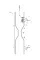
- FIG. 2 is a diagram for explaining the doping step using the optical fiber manufacturing apparatus according to the embodiment.
- FIG. 3 is a diagram for explaining an addition step using an optical fiber manufacturing apparatus according to a modified example.
- FIG. 4 is a graph showing the change in fluorine concentration distribution accompanying the heating process during reservoir formation.
- FIG. 5 is a graph showing the relationship between the halogen concentration and the defective rate of the reservoir.
- FIG. 6 is a graph showing the relationship between chlorine concentration and the defective rate of the reservoir.
- the reservoir is made of glass with a high chlorine concentration
- the chlorine reacts with alkali metal elements and alkaline earth metal elements in the reservoir and crystallizes. If the crystals are dispersed as fine powder into the glass pipe, the fine powder acts as a nucleus to cause silica glass crystallization in the glass pipe. As a result, the core material for the optical fiber preform may be defective, and the yield of the optical fiber may decrease.
- the chlorine concentration is too low, it may be difficult to control the shape of the reservoir, or the reservoir may crack during the manufacture of the reservoir or during diffusion doping using the reservoir.
- the present disclosure aims to provide a reservoir that can improve optical fiber yield and reservoir processability, and can reduce reservoir cracking, an optical fiber manufacturing method, and an optical fiber manufacturing device.
- a reservoir capable of improving optical fiber yield and reservoir processability, and reducing reservoir cracking, an optical fiber manufacturing method, and an optical fiber manufacturing apparatus.
- a reservoir according to one embodiment of the present disclosure is used in the manufacture of an optical fiber preform, and is a reservoir in which a raw material containing an alkali metal element or an alkaline earth metal element is placed when an alkali metal element or an alkaline earth metal element is added by thermal diffusion to a glass pipe made of silica-based glass, and is made of silica-based glass having a sum of a fluorine concentration and a chlorine concentration of 1,500 ppm or more and 20,000 ppm or less.
- the reservoir may be made of silica-based glass in which the sum of the fluorine concentration and the chlorine concentration is 3,500 ppm or more and 18,000 ppm or less.
- the yield of the optical fiber and the processability of the reservoir can be further improved.
- the reservoir cracking can be further reduced.
- the reservoir may be made of silica-based glass in which the sum of the fluorine concentration and the chlorine concentration is 3,500 ppm or more and 13,000 ppm or less.
- the yield of the optical fiber and the processability of the reservoir can be further improved.
- the reservoir cracking can be further reduced.
- the reservoir may be made of silica-based glass with a chlorine concentration of 20 ppm or more. In this case, the reservoir can be further prevented from cracking.
- the reservoir may be made of silica-based glass having a chlorine concentration of 50 ppm or more. In this case, the reservoir can be further prevented from cracking.
- the reservoir may be a separate member from the glass pipe and may have a connection end that is fusion-connected to the glass pipe. In this case, the reservoir can be removed from the glass pipe and fusion-connected to another glass pipe for use.
- a method for manufacturing an optical fiber according to one aspect of the present disclosure may include a step of adding an alkali metal element or an alkaline earth metal element to an inner surface of a glass pipe made of silica-based glass by using any of the reservoirs (1) to (6) above.
- the reservoir since the reservoir is used, it is possible to improve the yield of the optical fiber and the processability of the reservoir, and also to reduce the cracking of the reservoir.
- An optical fiber manufacturing apparatus may include a reservoir as described above in any one of (1) to (6), the reservoir being connected to a glass pipe, and a heat source for heating the reservoir, and may add an alkali metal element or an alkaline earth metal element to the inner surface of the glass pipe.
- the optical fiber manufacturing apparatus since the optical fiber manufacturing apparatus includes the above-mentioned reservoir, it is possible to improve the yield of the optical fiber and the processability of the reservoir, and also to reduce the cracking of the reservoir.
- FIG. 1 is a flowchart showing a method for manufacturing an optical fiber according to an embodiment.
- the method for manufacturing an optical fiber includes a preparation process S1, an addition process S2, a diameter reduction process S3, an etching process S4, a collapse process S5, a stretch grinding process S6, a rod-in collapse process S7, an OVD (Outside Vapor Deposition) process S8, and a drawing process S9.
- the optical fiber is manufactured through these processes S1 to S9 in this order.
- the method for manufacturing an optical fiber is carried out using an optical fiber manufacturing apparatus 10 (see FIG. 2).
- the preparation step S1 is a step of preparing a glass pipe into which an alkali metal group is to be diffused as a dopant.
- the alkali metal group is a general term for alkali metal elements and alkaline earth metal elements.
- the glass pipe is made of silica (quartz)-based glass.
- Silica-based glass is mainly composed of silica and contains 90% or more of silica. Silica-based glass may contain 95% or more of silica.
- the silica-based glass rod that is the base of this glass pipe is manufactured, for example, by the VAD (vapor phase axial deposition) method.
- the pipe is manufactured by drilling holes in the cylindrical body and then stretching it.
- the silica-based glass rod that is the base of the glass pipe contains a certain concentration of chlorine and fluorine.
- the mass fraction of other dopants and impurities is 10 ppm or less.
- the mass fraction is the ratio of the mass of the element of interest to the total mass, and is expressed as (mass of the element of interest) / (total mass).
- the mass fraction is referred to as "concentration”.
- the doping step S2 is a step of doping an alkali metal group by a diffusion method to the inner surface of the glass pipe 2 (see FIG. 2) made of silica-based glass.
- potassium (K) element is added as a dopant of the alkali metal group
- potassium bromide (KBr) is used as the raw material 5 (see FIG. 2) containing the alkali metal group.
- KBr potassium iodide
- RbBr rubidium bromide
- RbI rubidium iodide
- the diameter reduction step S3 is a step of reducing the diameter of the glass pipe to which the alkali metal group has been added.
- the etching step S4 is a step of etching the inner surface of the glass pipe. The etching step S4 makes it possible to remove the impurities by scraping the inner surface of the glass pipe, which contains a high concentration of impurities added together with the alkali metal group.
- the collapse step S5 is a step of solidifying the glass pipe to form a glass rod.
- the drawing and grinding process S6 is a process in which the glass rod is drawn and the outer periphery of the glass rod is ground to form a core rod that will become the core portion.
- the rod-in-collapse process S7 is a process in which a first cladding portion is provided on the outside of the core portion.
- the OVD process S8 is a process in which a rod formed by integrating the core portion and the first cladding portion is drawn to a predetermined diameter, and then a second cladding portion containing fluorine is synthesized on the outside of the rod by the OVD method. This produces an optical fiber preform.
- the drawing process S9 is a process in which the optical fiber preform is drawn. This produces an optical fiber.
- the optical fiber manufacturing apparatus 10 includes a reservoir 1, a heat source 3, and a heat source 4.
- the optical fiber manufacturing apparatus 10 is used in the manufacture of the optical fiber, specifically in the doping process S2. That is, the reservoir 1 according to the embodiment is used in the manufacture of the optical fiber, specifically in the doping process S2.
- the reservoir 1 is made of silica-based glass and contains fluorine and chlorine. Silica-based glass is mainly composed of silica and contains 90% or more of silica. Silica-based glass may contain 95% or more of silica.
- the silica-based glass rod that is the base of the glass pipe of the reservoir 1 is manufactured, for example, by the VAD (vapor phase axial deposition) method.
- the reservoir 1 is manufactured by drilling holes in the cylindrical body and then stretching it.
- the sum of the fluorine concentration and chlorine concentration in the reservoir 1 is 1500 ppm or more and 20000 ppm or less. This can improve the yield of the optical fiber and the processability of the reservoir 1.
- the cracking of the reservoir 1 can be reduced.
- the sum of the fluorine concentration and the chlorine concentration in the reservoir 1 may be 3500 ppm or more and 18000 ppm or less, or may be 3500 ppm or more and 13000 ppm or less.
- the chlorine concentration in the reservoir 1 is 20 ppm or more. This can further reduce the cracking of the reservoir 1.
- the chlorine concentration in the reservoir 1 may be 50 ppm or more.
- reservoir 1 when reservoir 1 is made of glass with a high chlorine concentration, chlorine reacts with alkali metal elements and alkaline earth metal elements in reservoir 1 to crystallize. If the crystals scatter as fine powder into glass pipe 2, silica glass will also crystallize in glass pipe 2, with the fine powder acting as nuclei. This can result in defective core material for the optical fiber preform, which can lead to a decrease in optical fiber yield.
- the sum of the fluorine concentration and chlorine concentration in reservoir 1 is 20,000 ppm or less, and may be 18,000 ppm or less, or 13,000 ppm or less, so that optical fiber yield can be improved.
- glass materials with low chlorine concentrations are manufactured by not sufficiently removing impurities with chlorine gas, or by replacing chlorine with fluorine-based gas.
- the transmission loss worsens due to absorption loss caused by impurities.
- the latter glass material contains a lot of fluorine, so the fluorine on the surface is desorbed when heated during the shaping process of the reservoir. If too much fluorine is desorbed, the viscosity increases only on the surface, generating tensile stress. This causes cracks to form on the surface, making the reservoir more likely to break during reservoir manufacturing or diffusion doping. If the reservoir breaks during diffusion doping, the yield of core material for optical fiber preforms will decrease, which may ultimately result in a decrease in the yield of optical fiber.
- the sum of the fluorine concentration and chlorine concentration in reservoir 1 is 1500 ppm or more, and may be 3500 ppm or more, so deterioration of the optical fiber transmission loss caused by insufficient removal of impurities by chlorine gas is reduced. In addition, the occurrence of cracks on the surface due to desorption of halogen elements is reduced. Therefore, breakage of reservoir 1 is reduced. As a result, deterioration of the optical fiber yield is reduced.
- the reservoir 1 is a glass pipe connected to the glass pipe 2 to which the alkali metal group is added.
- the reservoir 1 has a large diameter portion 11, a small diameter portion 12, a first connection portion 13, and a second connection portion 14.
- the reservoir 1 functions as a mounting portion in which the raw material 5 containing the alkali metal group is mounted when the alkali metal group is added to the glass pipe 2 by thermal diffusion.
- the raw material 5 is mounted mainly in the large diameter portion 11.
- the outer diameter of the large diameter portion 11 is equal to the outer diameter of the glass pipe 2.
- the small diameter portion 12 is disposed between the first connection portion 13 and the second connection portion 14.
- the outer diameter of the small diameter portion 12 is smaller than the outer diameter of the glass pipe 2 and smaller than the outer diameter of the large diameter portion 11.
- the first connection portion 13 connects the thick diameter portion 11 and the first end of the thin diameter portion 12. As described above, the outer diameter of the thin diameter portion 12 is smaller than the outer diameter of the thick diameter portion 11, so the first connection portion 13 forms a step. The height of the step caused by the first connection portion 13 is, for example, about 1 mm.
- the first connection portion 13 has a tapered shape. The outer diameter of the first connection portion 13 gradually decreases from the thick diameter portion 11 to the thin diameter portion 12.
- the second connection part 14 connects the second end of the thin diameter part 12 to the glass pipe 2.
- the outer diameter of the thin diameter part 12 is smaller than the outer diameter of the glass pipe 2, so the second connection part 14 forms a step.
- the height of the step caused by the second connection part 14 is equal to the height of the step caused by the first connection part 13.
- the second connection part 14 has a tapered shape. The outer diameter of the second connection part 14 gradually decreases from the glass pipe 2 to the thin diameter part 12.
- the reservoir 1 and the glass pipe 2 are made of a single member and have the same composition before the addition step S2.
- the reservoir 1 and the glass pipe 2 are formed, for example, from a single glass pipe.
- the portion of the single glass pipe that will become the narrow diameter portion 12 is heated to reduce its diameter. This results in the reservoir 1 and the glass pipe 2 being formed in a connected state.
- a heat source 3 is disposed outside the reservoir 1.
- the heat source 3 is an external heat source for heating the reservoir 1. More specifically, the heat source 3 is an external heat source for heating the raw material 5 placed in the reservoir 1.
- a heat source 4 is disposed outside the glass pipe 2.
- the heat source 4 is an external heat source for heating the glass pipe 2.
- the heat sources 3 and 4 are, for example, oxyhydrogen burners.
- the heat sources 3 and 4 may be induction furnaces, resistance furnaces, or the like.
- the raw material 5 is heated by the heat source 3 to generate raw material vapor.
- the heating temperature is, for example, 600°C or higher and 1000°C or lower.
- the generated raw material vapor is introduced into the glass pipe 2 together with a carrier gas, while the glass pipe 2 is heated from the outside by the heat source 4.
- the carrier gas contains, for example, oxygen.
- the flow rate of the carrier gas is 1 SLM or higher (volume of gas flowing per minute under standard conditions (25°C, 100 kPa)) and 3 SLM or lower.
- the first connection part 13, which forms a step is present on the side of the large diameter part 11 closer to the glass pipe 2, so that scattering of the raw material 5 into the inside of the glass pipe 2 by the carrier gas is reduced.
- the glass pipe 2 is heated by moving the heat source 4 along the longitudinal direction of the glass pipe 2.
- the glass pipe 2 is heated by traversing the heat source 4 at a speed of 30 mm/min to 60 mm/min for a total of 8 turns to 15 turns so that the temperature of the outer surface of the glass pipe 2 is 1400°C to 2000°C. This causes the alkali metal group to be diffused and doped into the inner surface of the glass pipe 2.
- FIG. 3 is a diagram for explaining the doping process using an optical fiber manufacturing apparatus according to a modified example.
- An optical fiber manufacturing apparatus 10A according to a modified example differs from the optical fiber manufacturing apparatus 10 in that it includes a reservoir 1A instead of the reservoir 1 (see FIG. 2).
- the reservoir 1A according to the modified example has a different shape from the reservoir 1.
- the reservoir 1A has the same composition as the reservoir 1. That is, the reservoir 1A is made of silica-based glass and contains fluorine and chlorine.
- the sum of the fluorine concentration and the chlorine concentration in the reservoir 1A is 1500 ppm or more and 20000 ppm or less.
- the sum of the fluorine concentration and the chlorine concentration in the reservoir 1A may be 3500 ppm or more and 18000 ppm or less, or may be 3500 ppm or more and 13000 ppm or less.
- the chlorine concentration in the reservoir 1A is 20 ppm or more.
- the chlorine concentration in the reservoir 1A may be 50 ppm or more.
- the reservoir 1A has a large diameter portion 21, a first small diameter portion 22, a second small diameter portion 23, a first connection portion 24, and a second connection portion 25.
- the raw material 5 is placed mainly in the large diameter portion 21.
- the outer diameter of the large diameter portion 21 is larger than the outer diameter of the glass pipe 2.
- the outer diameters of the first small diameter portion 22 and the second small diameter portion 23 are equal to the outer diameter of the glass pipe 2 and smaller than the outer diameter of the large diameter portion 21.
- the first small diameter portion 22 is connected to the glass pipe 2.
- the first connection portion 24 connects the large diameter portion 21 and the first thin diameter portion 22.
- the outer diameter of the first thin diameter portion 22 is smaller than the outer diameter of the large diameter portion 21, so the first connection portion 24 forms a step.
- the height of the step caused by the first connection portion 24 is, for example, about 1 mm.
- the first connection portion 24 has a tapered shape. The outer diameter of the first connection portion 24 gradually decreases from the large diameter portion 21 toward the first thin diameter portion 22.
- the second connection portion 25 connects the large diameter portion 21 and the second thin diameter portion 23.
- the outer diameter of the second thin diameter portion 23 is smaller than the outer diameter of the large diameter portion 21, so the second connection portion 25 forms a step.
- the height of the step caused by the second connection portion 25 is, for example, about 1 mm.
- the second connection portion 25 has a tapered shape. The outer diameter of the second connection portion 25 gradually decreases from the large diameter portion 21 toward the second thin diameter portion 23.
- the reservoir 1A is formed, for example, from a single glass pipe.
- the portion of the single glass pipe that will become the large diameter portion 21 is heated while increasing the gas pressure inside the glass pipe, thereby expanding and enlarging the diameter. In this way, the reservoir 1A is obtained.
- the reservoir 1A and the glass pipe 2 are formed from separate members.
- the reservoir 1A is integrated with the glass pipe 2 by melt-connecting the first small diameter portion 22 to the glass pipe 2.
- the first small diameter portion 22 has a connection end 22a that is melt-connected to the glass pipe 2.
- the reservoir 1A and the glass pipe 2 do not necessarily have the same composition even before the addition step S2, and may have different compositions.
- the first connection part 24, which forms a step is present on the side of the large diameter part 21 closer to the glass pipe 2, so that the scattering of the raw material 5 into the inside of the glass pipe 2 by the carrier gas is reduced.
- the reservoir 1A can be removed from the glass pipe 2, and the removed reservoir 1A can be melted and connected again to another glass pipe 2 for use.
- Figure 4 is a graph showing the change in the concentration distribution of fluorine due to the heating process when forming the reservoir.
- reservoir 1A was used from the viewpoint of ease of production.
- the heating temperature during processing was set to 1000°C or higher and 2000°C or lower. By keeping the temperature in this temperature range, the viscosity of the glass decreases and the workability of the glass increases.
- the vertical axis in Figure 4 indicates the fluorine concentration.
- the horizontal axis indicates the difference between the radial position from the central axis of the reservoir and the inner radius of the reservoir divided by the thickness (wall thickness) of the reservoir.
- the position of 0 on the horizontal axis corresponds to the inner surface of the reservoir, and the position of 1 on the horizontal axis corresponds to the outer surface of the reservoir.
- the fluorine concentration before heating is approximately 20,000 ppm at the inner surface of the reservoir and decreases gradually toward the outer surface of the reservoir, reaching approximately 17,500 ppm at the outer surface of the reservoir.
- the fluorine concentration after heating is zero on the inner and outer surfaces of the reservoir.
- a sudden change in concentration occurs near the inner and outer surfaces of the reservoir.
- the fluorine concentration on the inner and outer surfaces is reduced by heating the reservoir to a high temperature.
- the change in the chlorine concentration distribution before and after heating was similar to the change in the fluorine concentration distribution.
- Table 1 shows the concentrations of the added elements in the glass material used in the above evaluation and the defective rate of the reservoirs.
- the added elements are chlorine (Cl), fluorine (F), and OH (hydroxyl group), a molecule that is easily added as an impurity.
- the sum of the chlorine and fluorine concentrations is shown as the halogen concentration.
- the defective rate of the reservoirs represents the probability that a reservoir that cannot be used for adding alkali metals is formed when reservoirs are manufactured 20 times by heating processing for each concentration condition.
- Figure 5 is a graph showing the relationship between halogen concentration and the defective rate of reservoirs.
- the vertical axis of Figure 5 shows the defective rate of reservoirs, and the horizontal axis shows halogen concentration, that is, the sum of fluorine concentration and chlorine concentration.
- halogen concentration that is, the sum of fluorine concentration and chlorine concentration.
- the number of defective reservoirs increased. This is thought to be because cracks occurred near the surface of the reservoir due to a sudden difference in concentration, as shown in Figure 4.
- reservoir defects occurred not due to cracks, but due to poor control of shape. This is thought to be because a large decrease in the additive concentration caused the viscosity of the entire glass to increase, deteriorating workability.
- the halogen concentration in the reservoir may be 1500 ppm or more and 20000 ppm or less, 3500 ppm or more and 18000 ppm or less, or 3500 ppm or more and 13000 ppm or less.
- Figure 6 is a graph showing the relationship between the chlorine concentration and the failure rate of the reservoir.
- the vertical axis of Figure 6 shows the failure rate of the reservoir, and the horizontal axis shows the chlorine concentration.
- Figure 6 shows the results for conditions 2 to 9, excluding conditions 1 and 10, which had high failure rates. From the results of Figure 6, it can be confirmed that the failure rate increases even when the chlorine concentration is low, so the chlorine concentration may be 20 ppm or more, or may be 50 ppm or more. Under the condition that the halogen concentration is within a certain range, as the chlorine decreases, the proportion of fluorine increases accordingly.
- the reservoir 1 and the glass pipe 2 may be made of separate members and fused together.
- the reservoir 1A and the glass pipe 2 may be made of a single member.
Landscapes
- Chemical & Material Sciences (AREA)
- Engineering & Computer Science (AREA)
- Life Sciences & Earth Sciences (AREA)
- Geochemistry & Mineralogy (AREA)
- Materials Engineering (AREA)
- Organic Chemistry (AREA)
- Chemical Kinetics & Catalysis (AREA)
- General Chemical & Material Sciences (AREA)
- General Life Sciences & Earth Sciences (AREA)
- Manufacturing & Machinery (AREA)
- Glass Compositions (AREA)
- Manufacture, Treatment Of Glass Fibers (AREA)
Abstract
Description
本出願は、2023年6月6日出願の日本出願第2023-092938号に基づく優先権を主張し、前記日本出願に記載された全ての記載内容を援用するものである。
リザーバが塩素濃度の高いガラスで構成される場合、リザーバにおいて、塩素がアルカリ金属元素およびアルカリ土類金属元素と反応して結晶化する。その結晶が微粉としてガラスパイプに飛散すると、微粉を核としてガラスパイプでもシリカガラスの結晶化が発生する。その結果、光ファイバ母材用のコア材が不良となり、光ファイバの歩留が悪化するおそれがある。一方、塩素濃度が低すぎる場合、リザーバの形状制御が困難になったり、リザーバの製造中やリザーバを用いた拡散添加中にリザーバが割れたりするおそれがある。
本開示によれば、光ファイバの歩留およびリザーバの加工性を向上可能、かつ、リザーバの割れを低減可能なリザーバ、光ファイバの製造方法および光ファイバの製造装置が提供される。
最初に、本開示の実施態様の内容を列記して説明する。
(1)本開示の一態様に係るリザーバは、光ファイバ母材の製造に用いられ、シリカ系ガラスで構成されるガラスパイプに熱拡散によりアルカリ金属元素またはアルカリ土類金属元素を添加する際に、アルカリ金属元素またはアルカリ土類金属元素を含む原料が設置されるリザーバであって、フッ素濃度および塩素濃度の総和が1500ppm以上20000ppm以下であるシリカ系ガラスで構成される。
このリザーバでは、光ファイバの歩留およびリザーバの加工性を向上することができる。また、リザーバの割れを低減することができる。
この場合、上記リザーバを用いるので、光ファイバの歩留およびリザーバの加工性を向上することができる。また、リザーバの割れを低減することができる。
この場合、光ファイバの製造装置が上記リザーバを備えるので、光ファイバの歩留およびリザーバの加工性を向上することができる。また、リザーバの割れを低減することができる。
本実施形態に係るリザーバおよび光ファイバの製造方法の具体例を、必要により図面を参照しつつ説明する。なお、本開示はこれらの例示に限定されず、請求の範囲によって示され、請求の範囲と均等の意味および範囲内でのすべての変更が含まれることが意図される。以下の説明では、図面の説明において同一の要素には同一の符号を付し、重複する説明を省略する。

2…ガラスパイプ
3,4…熱源
5…原料
10,10A…製造装置
11…太径部
12…細径部
13…第1接続部
14…第2接続部
21…太径部
22…第1細径部
22a…接続端
23…第2細径部
24…第1接続部
25…第2接続部
Claims (8)
- 光ファイバ母材の製造に用いられ、シリカ系ガラスで構成されるガラスパイプに熱拡散によりアルカリ金属元素またはアルカリ土類金属元素を添加する際に、アルカリ金属元素またはアルカリ土類金属元素を含む原料が設置されるリザーバであって、
フッ素濃度および塩素濃度の総和が1500ppm以上20000ppm以下であるシリカ系ガラスで構成される、
リザーバ。 - フッ素濃度および塩素濃度の総和が3500ppm以上18000ppm以下であるシリカ系ガラスで構成される、
請求項1に記載のリザーバ。 - フッ素濃度および塩素濃度の総和が3500ppm以上13000ppm以下であるシリカ系ガラスで構成される、
請求項1に記載のリザーバ。 - 塩素濃度が20ppm以上であるシリカ系ガラスで構成される、
請求項1から請求項3のいずれか一項に記載のリザーバ。 - 塩素濃度が50ppm以上であるシリカ系ガラスで構成される、
請求項1から請求項3のいずれか一項に記載のリザーバ。 - 前記ガラスパイプとは別部材であり、前記ガラスパイプに溶融接続される接続端を有している、
請求項1から請求項5のいずれか一項に記載のリザーバ。 - 請求項1から請求項6のいずれか一項のリザーバを用い、シリカ系ガラスで構成されるガラスパイプの内表面にアルカリ金属元素またはアルカリ土類金属元素を添加する工程を含む、
光ファイバの製造方法。 - 請求項1から請求項6のいずれか一項のリザーバであって、前記ガラスパイプに接続されるリザーバと、
前記リザーバを加熱する熱源と、を備え、
前記ガラスパイプの内表面にアルカリ金属元素またはアルカリ土類金属元素を添加する、
光ファイバの製造装置。
Priority Applications (3)
| Application Number | Priority Date | Filing Date | Title |
|---|---|---|---|
| CN202480033496.4A CN121152774A (zh) | 2023-06-06 | 2024-05-17 | 贮存器、光纤的制造方法及光纤的制造装置 |
| JP2025526035A JPWO2024252898A1 (ja) | 2023-06-06 | 2024-05-17 | |
| DKPA202530761A DK202530761A1 (en) | 2023-06-06 | 2025-11-24 | Reservoir, method for producing optical fiber, and device for producing optical fiber |
Applications Claiming Priority (2)
| Application Number | Priority Date | Filing Date | Title |
|---|---|---|---|
| JP2023092938 | 2023-06-06 | ||
| JP2023-092938 | 2023-06-06 |
Publications (1)
| Publication Number | Publication Date |
|---|---|
| WO2024252898A1 true WO2024252898A1 (ja) | 2024-12-12 |
Family
ID=93795199
Family Applications (1)
| Application Number | Title | Priority Date | Filing Date |
|---|---|---|---|
| PCT/JP2024/018367 Ceased WO2024252898A1 (ja) | 2023-06-06 | 2024-05-17 | リザーバ、光ファイバの製造方法および光ファイバの製造装置 |
Country Status (4)
| Country | Link |
|---|---|
| JP (1) | JPWO2024252898A1 (ja) |
| CN (1) | CN121152774A (ja) |
| DK (1) | DK202530761A1 (ja) |
| WO (1) | WO2024252898A1 (ja) |
Citations (3)
| Publication number | Priority date | Publication date | Assignee | Title |
|---|---|---|---|---|
| JP2005537210A (ja) * | 2002-08-28 | 2005-12-08 | コーニング インコーポレイテッド | 低損失光ファイバおよびその製造方法 |
| WO2018110234A1 (ja) * | 2016-12-12 | 2018-06-21 | 住友電気工業株式会社 | 光ファイバ母材製造方法、光ファイバ母材、および光ファイバ |
| WO2020027063A1 (ja) * | 2018-07-31 | 2020-02-06 | 住友電気工業株式会社 | 光ファイバ |
-
2024
- 2024-05-17 CN CN202480033496.4A patent/CN121152774A/zh active Pending
- 2024-05-17 WO PCT/JP2024/018367 patent/WO2024252898A1/ja not_active Ceased
- 2024-05-17 JP JP2025526035A patent/JPWO2024252898A1/ja active Pending
-
2025
- 2025-11-24 DK DKPA202530761A patent/DK202530761A1/en unknown
Patent Citations (3)
| Publication number | Priority date | Publication date | Assignee | Title |
|---|---|---|---|---|
| JP2005537210A (ja) * | 2002-08-28 | 2005-12-08 | コーニング インコーポレイテッド | 低損失光ファイバおよびその製造方法 |
| WO2018110234A1 (ja) * | 2016-12-12 | 2018-06-21 | 住友電気工業株式会社 | 光ファイバ母材製造方法、光ファイバ母材、および光ファイバ |
| WO2020027063A1 (ja) * | 2018-07-31 | 2020-02-06 | 住友電気工業株式会社 | 光ファイバ |
Also Published As
| Publication number | Publication date |
|---|---|
| JPWO2024252898A1 (ja) | 2024-12-12 |
| CN121152774A (zh) | 2025-12-16 |
| DK202530761A1 (en) | 2025-12-02 |
Similar Documents
| Publication | Publication Date | Title |
|---|---|---|
| US10550030B2 (en) | Optical fiber | |
| CN102627398B (zh) | 用于制备光纤预制件的方法 | |
| CN102627400B (zh) | 用于制备光纤预制件的方法 | |
| US11345627B2 (en) | Method of manufacturing optical fiber preform and optical fiber preform | |
| CN110389405B (zh) | 光纤 | |
| CN106082630A (zh) | 光纤预制件 | |
| CN109250898B (zh) | 光纤预制件 | |
| JP7276134B2 (ja) | 光ファイバ母材の製造方法、及び、光ファイバの製造方法 | |
| DK182201B1 (en) | Production method for optical fiber base material, and optical fiber base material | |
| WO2014178361A1 (ja) | 光ファイバ母材 | |
| WO2024252898A1 (ja) | リザーバ、光ファイバの製造方法および光ファイバの製造装置 | |
| DK182061B1 (en) | Method for producing optical fiber base material, and optical fiber base material | |
| JP2013136485A (ja) | 光ファイバ母材製造方法 | |
| WO2023286608A1 (ja) | 光ファイバ及び光ファイバ母材 | |
| WO2024048356A1 (ja) | 光ファイバ母材の製造方法及び光ファイバ母材 |
Legal Events
| Date | Code | Title | Description |
|---|---|---|---|
| WWE | Wipo information: entry into national phase |
Ref document number: 18724664 Country of ref document: US |
|
| 121 | Ep: the epo has been informed by wipo that ep was designated in this application |
Ref document number: 24819131 Country of ref document: EP Kind code of ref document: A1 |
|
| ENP | Entry into the national phase |
Ref document number: 2025526035 Country of ref document: JP Kind code of ref document: A |
|
| WWE | Wipo information: entry into national phase |
Ref document number: 2025526035 Country of ref document: JP |
|
| WWE | Wipo information: entry into national phase |
Ref document number: PA202530761 Country of ref document: DK |
|
| WWP | Wipo information: published in national office |
Ref document number: PA202530761 Country of ref document: DK |
|
| NENP | Non-entry into the national phase |
Ref country code: DE |