WO2024252895A1 - 積層フィルム - Google Patents
積層フィルム Download PDFInfo
- Publication number
- WO2024252895A1 WO2024252895A1 PCT/JP2024/018294 JP2024018294W WO2024252895A1 WO 2024252895 A1 WO2024252895 A1 WO 2024252895A1 JP 2024018294 W JP2024018294 W JP 2024018294W WO 2024252895 A1 WO2024252895 A1 WO 2024252895A1
- Authority
- WO
- WIPO (PCT)
- Prior art keywords
- light
- laminated film
- layer
- guide layer
- light guide
- Prior art date
- Legal status (The legal status is an assumption and is not a legal conclusion. Google has not performed a legal analysis and makes no representation as to the accuracy of the status listed.)
- Ceased
Links
Images





Classifications
-
- G—PHYSICS
- G02—OPTICS
- G02B—OPTICAL ELEMENTS, SYSTEMS OR APPARATUS
- G02B6/00—Light guides; Structural details of arrangements comprising light guides and other optical elements, e.g. couplings
- G02B6/0001—Light guides; Structural details of arrangements comprising light guides and other optical elements, e.g. couplings specially adapted for lighting devices or systems
- G02B6/0011—Light guides; Structural details of arrangements comprising light guides and other optical elements, e.g. couplings specially adapted for lighting devices or systems the light guides being planar or of plate-like form
-
- B—PERFORMING OPERATIONS; TRANSPORTING
- B32—LAYERED PRODUCTS
- B32B—LAYERED PRODUCTS, i.e. PRODUCTS BUILT-UP OF STRATA OF FLAT OR NON-FLAT, e.g. CELLULAR OR HONEYCOMB, FORM
- B32B17/00—Layered products essentially comprising sheet glass, or glass, slag, or like fibres
-
- B—PERFORMING OPERATIONS; TRANSPORTING
- B32—LAYERED PRODUCTS
- B32B—LAYERED PRODUCTS, i.e. PRODUCTS BUILT-UP OF STRATA OF FLAT OR NON-FLAT, e.g. CELLULAR OR HONEYCOMB, FORM
- B32B7/00—Layered products characterised by the relation between layers; Layered products characterised by the relative orientation of features between layers, or by the relative values of a measurable parameter between layers, i.e. products comprising layers having different physical, chemical or physicochemical properties; Layered products characterised by the interconnection of layers
- B32B7/02—Physical, chemical or physicochemical properties
- B32B7/023—Optical properties
-
- F—MECHANICAL ENGINEERING; LIGHTING; HEATING; WEAPONS; BLASTING
- F21—LIGHTING
- F21K—NON-ELECTRIC LIGHT SOURCES USING LUMINESCENCE; LIGHT SOURCES USING ELECTROCHEMILUMINESCENCE; LIGHT SOURCES USING CHARGES OF COMBUSTIBLE MATERIAL; LIGHT SOURCES USING SEMICONDUCTOR DEVICES AS LIGHT-GENERATING ELEMENTS; LIGHT SOURCES NOT OTHERWISE PROVIDED FOR
- F21K9/00—Light sources using semiconductor devices as light-generating elements, e.g. using light-emitting diodes [LED] or lasers
- F21K9/60—Optical arrangements integrated in the light source, e.g. for improving the colour rendering index or the light extraction
- F21K9/61—Optical arrangements integrated in the light source, e.g. for improving the colour rendering index or the light extraction using light guides
-
- F—MECHANICAL ENGINEERING; LIGHTING; HEATING; WEAPONS; BLASTING
- F21—LIGHTING
- F21S—NON-PORTABLE LIGHTING DEVICES; SYSTEMS THEREOF; VEHICLE LIGHTING DEVICES SPECIALLY ADAPTED FOR VEHICLE EXTERIORS
- F21S2/00—Systems of lighting devices, not provided for in main groups F21S4/00 - F21S10/00 or F21S19/00, e.g. of modular construction
-
- F—MECHANICAL ENGINEERING; LIGHTING; HEATING; WEAPONS; BLASTING
- F21—LIGHTING
- F21V—FUNCTIONAL FEATURES OR DETAILS OF LIGHTING DEVICES OR SYSTEMS THEREOF; STRUCTURAL COMBINATIONS OF LIGHTING DEVICES WITH OTHER ARTICLES, NOT OTHERWISE PROVIDED FOR
- F21V9/00—Elements for modifying spectral properties, polarisation or intensity of the light emitted, e.g. filters
-
- G—PHYSICS
- G02—OPTICS
- G02B—OPTICAL ELEMENTS, SYSTEMS OR APPARATUS
- G02B6/00—Light guides; Structural details of arrangements comprising light guides and other optical elements, e.g. couplings
- G02B6/0001—Light guides; Structural details of arrangements comprising light guides and other optical elements, e.g. couplings specially adapted for lighting devices or systems
- G02B6/0011—Light guides; Structural details of arrangements comprising light guides and other optical elements, e.g. couplings specially adapted for lighting devices or systems the light guides being planar or of plate-like form
- G02B6/0033—Means for improving the coupling-out of light from the light guide
- G02B6/005—Means for improving the coupling-out of light from the light guide provided by one optical element, or plurality thereof, placed on the light output side of the light guide
- G02B6/0055—Reflecting element, sheet or layer
-
- G—PHYSICS
- G02—OPTICS
- G02B—OPTICAL ELEMENTS, SYSTEMS OR APPARATUS
- G02B6/00—Light guides; Structural details of arrangements comprising light guides and other optical elements, e.g. couplings
- G02B6/0001—Light guides; Structural details of arrangements comprising light guides and other optical elements, e.g. couplings specially adapted for lighting devices or systems
- G02B6/0011—Light guides; Structural details of arrangements comprising light guides and other optical elements, e.g. couplings specially adapted for lighting devices or systems the light guides being planar or of plate-like form
- G02B6/0065—Manufacturing aspects; Material aspects
-
- G—PHYSICS
- G02—OPTICS
- G02B—OPTICAL ELEMENTS, SYSTEMS OR APPARATUS
- G02B6/00—Light guides; Structural details of arrangements comprising light guides and other optical elements, e.g. couplings
- G02B6/0001—Light guides; Structural details of arrangements comprising light guides and other optical elements, e.g. couplings specially adapted for lighting devices or systems
- G02B6/0011—Light guides; Structural details of arrangements comprising light guides and other optical elements, e.g. couplings specially adapted for lighting devices or systems the light guides being planar or of plate-like form
- G02B6/0081—Mechanical or electrical aspects of the light guide and light source in the lighting device peculiar to the adaptation to planar light guides, e.g. concerning packaging
- G02B6/0095—Light guides as housings, housing portions, shelves, doors, tiles, windows, or the like
-
- F—MECHANICAL ENGINEERING; LIGHTING; HEATING; WEAPONS; BLASTING
- F21—LIGHTING
- F21V—FUNCTIONAL FEATURES OR DETAILS OF LIGHTING DEVICES OR SYSTEMS THEREOF; STRUCTURAL COMBINATIONS OF LIGHTING DEVICES WITH OTHER ARTICLES, NOT OTHERWISE PROVIDED FOR
- F21V2200/00—Use of light guides, e.g. fibre optic devices, in lighting devices or systems
- F21V2200/20—Use of light guides, e.g. fibre optic devices, in lighting devices or systems of light guides of a generally planar shape
-
- F—MECHANICAL ENGINEERING; LIGHTING; HEATING; WEAPONS; BLASTING
- F21—LIGHTING
- F21Y—INDEXING SCHEME ASSOCIATED WITH SUBCLASSES F21K, F21L, F21S and F21V, RELATING TO THE FORM OR THE KIND OF THE LIGHT SOURCES OR OF THE COLOUR OF THE LIGHT EMITTED
- F21Y2115/00—Light-generating elements of semiconductor light sources
- F21Y2115/10—Light-emitting diodes [LED]
Definitions
- the present invention relates to a laminated film.
- a method has been proposed to realize lighting and displays with high design value or entertainment value by placing laminated films on glass, windows, walls, floors, ceilings, etc.
- Patent Document 1 discloses a configuration having a light guide layer with a light receiving side that receives light emitted from a light source, and a light distribution control structure for the light propagating within the light guide layer.
- Patent Document 1 allows light from the light source to enter the light guide layer only from the end portions, such as the side surfaces, of the light guide layer, leaving room for improvement in terms of incidence efficiency.
- the object of the present invention is to provide a laminated film that has a high incidence efficiency of light from a light source even when the thickness of the laminated film is reduced.
- the laminated film according to one aspect of the present invention is a laminated film in which multiple layers are laminated, and has an end surface along the lamination direction, a light incident surface that intersects with the end surface and allows light from a light source to enter, a light guide layer that guides the light incident through the light incident surface, and a light extraction layer that includes a light extraction portion that can extract the light guided by the light guide layer, and the thickness between a first surface, which is the surface of the light extraction layer on the side opposite to the side where the light guide layer is arranged, and a second surface, which is the surface of the light guide layer on the side opposite to the side where the light extraction layer is arranged, is 1000 ⁇ m or less.
- the present invention it is possible to provide a laminated film that has a high incidence efficiency of light from a light source, even when the thickness of the laminated film is reduced.
- FIG. 1 is a schematic cross-sectional view of a laminated film according to an embodiment.
- FIG. 2 is a schematic plan view of a light extraction layer according to an embodiment. 3 is a cross-sectional view taken along line III-III in FIG. 2.
- FIG. 2 is a schematic cross-sectional view of a light extraction portion according to an embodiment.
- FIG. 4 is a schematic cross-sectional view of a laminated film according to a first modified example.
- FIG. 11 is a schematic cross-sectional view of a laminated film according to a second modified example.
- FIG. 11 is a schematic cross-sectional view of a laminated film according to a third modified example.
- FIG. 13 is a schematic cross-sectional view of a laminated film according to a fourth modified example.
- FIG. 1 is a schematic cross-sectional view of a laminated film according to an embodiment.
- a Cartesian coordinate system having an X-axis, Y-axis, and Z-axis is used to represent directions.
- the X-axis, Y-axis, and Z-axis are approximately perpendicular to one another.
- the direction in which the X-axis arrow points is expressed as the +X direction or +X side, and the direction opposite the +X direction is expressed as the -X direction or -X side.
- the direction in which the Y-axis arrow points is expressed as the +Y direction or +Y side, and the direction opposite the +Y direction is expressed as the -Y direction or -Y side.
- the direction in which the Z-axis arrow points is expressed as the +Z direction or +Z side, and the direction opposite the +Z direction is expressed as the -Z direction or -Z side.
- the Z direction along the Z axis indicates the stacking direction of each layer constituting the laminated film according to the embodiment.
- plane view refers to viewing an object from the Z direction.
- the +Z direction is referred to as "upper”, and the -Z direction is referred to as "lower”.
- thickness refers to the length of an object in the Z direction, i.e., the stacking direction of each layer.
- the cross-sectional view shows a cross section parallel to the YZ plane of the laminated film according to the embodiment.
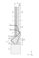
- Fig. 1 is a cross-sectional view showing an example of a laminated film 10 according to the first embodiment.
- the laminated film 10 is a laminated film in which a plurality of layers are laminated.
- the laminated film 10 has an end surface 103 along the lamination direction (Z direction), a light incident surface 1b that intersects with the end surface 103 and allows light L from a light source 50 to enter, a light guide layer 1 that guides the light L incident through the light incident surface 1b, and a light extraction layer 2 including a light extraction portion 21 that can extract the light L guided by the light guide layer 1.
- the light source 50 is, for example, an LED (Light Emitting Diode) light source.
- Light L from the light source 50 enters the light guide layer 1 through the light incident surface 1b located in a region of the light guide layer 1 where the light extraction layer 2 and the light guide layer 1 do not overlap in a plan view.
- the region of the light incident surface 1b is a region of the upper surface 104 of the light guide layer 1 that is defined by the end 1a of the light guide layer 1 and the end 2a of the light extraction layer 2.
- the inclination angle of the light source 50 arranged on the light incident surface 1b with respect to the light guide layer 1 may be any angle as long as the light L from the light source 50 is incident on the light guide layer 1 through the light incident surface 1b and can be guided within the light guide layer 1.
- the light source 50 is fixed by an adhesive member or the like to a structure around the laminated film 10, such as an adherend on which the laminated film 10 is arranged.
- the laminated film 10 guides the light L incident from the light source 50 through the light guide layer 1, and extracts the light L from inside the light guide layer 1 to the outside through the light extraction section 21.
- the laminated film 10 can illuminate the space in which the laminated film 10 is placed, using the light L extracted from the light guide layer 1.
- the laminated film 10 can be placed on an adherend such as glass, a window, a wall, a floor, or a ceiling.
- the laminated film 10 can also be used as a flexible lighting film without being placed on an adherend.
- the laminated film 10 is placed by being attached to the surface of the adherend.
- the laminated film 10 can illuminate an indoor space, etc., when placed on an adherend such as window glass.
- the thickness t1 between the first surface 101 and the second surface 102 is 1000 ⁇ m or less.
- the first surface 101 is the surface of the light extraction layer 2 on the side opposite to the side on which the light guide layer 1 is arranged.
- the second surface 102 is the surface of the light guide layer 1 on the side opposite to the side on which the light extraction layer 2 is arranged.
- the thickness t1 between the first surface 101 and the second surface 102 can be 800 ⁇ m or less, 700 ⁇ m or less, 600 ⁇ m or less, 500 ⁇ m or less, 400 ⁇ m or less, or 300 ⁇ m or less.
- the lower limit is not particularly limited, but is, for example, 50 ⁇ m or more, 100 ⁇ m or more, or 200 ⁇ m or more.
- the laminate film 10 can reduce its own presence and make the laminate film 10 less noticeable. It can also be used as a film that emits light and has flexibility. In this embodiment, by reducing the presence of the laminate film 10, a laminate film 10 with high designability can be provided. Furthermore, the laminate film 10 can enhance the designability of the adherend on which the laminate film 10 is placed.
- the area of the end of the light guide layer is small, which may result in low efficiency of light entering the interior of the laminate film.
- the thickness of the laminate film becomes thinner, the area of the end of the laminate film where light from the light source enters becomes smaller, making it more difficult for light to enter the interior of the laminate film from the end, lowering the above-mentioned incidence efficiency.
- the thickness of the laminate film is made 1000 ⁇ m or less in order to improve the design of the laminate film, the thinness of the laminate film will result in low efficiency of light entering from the light source.
- the end 2a of the light extraction layer 2 can be located inside the light guide layer 1 more than the end 1a of the light guide layer 1.
- the distance between the end 2a of the light extraction layer 2 and the end 1a of the light guide layer 1 is 1 mm or more and 100 mm or less.
- the inside in a plan view means the side closer to the center of the laminated film 10 when the laminated film 10 is viewed in a plan view.
- the laminated film 10 allows light L from the light source 50 to be incident on the light guide layer 1 through the light incident surface 1b located in the area of the light guide layer 1 where the light extraction layer 2 and the light guide layer 1 do not overlap.
- the incidence efficiency of the light L into the laminated film 10 can be increased compared to the case where the light L is incident from the end 2a of the light guide layer 1.
- a laminated film 10 with high incidence efficiency of the light L from the light source 50 can be provided.
- the thickness t2 of the light guide layer 1 may be 30 ⁇ m or more. By making the thickness t2 of the light guide layer 1 30 ⁇ m or more, the efficiency of incidence of the light L from the light source 50 into the laminated film 10 can be increased.
- the light extraction layer 2 may be disposed on the side of the light guide layer 1 where the light source 50 is disposed.
- the thickness of the configuration consisting of the laminated film 10 and the light source 50 is the sum of the thickness of the light guide layer 1 and the thickness of the light source 50.
- the thickness of the configuration consisting of the laminated film and the light source is the sum of the thickness of the light guide layer, the thickness of the light extraction layer, and the thickness of the light source.
- the thickness of the configuration consisting of the laminated film 10 and the light source 50 can be made thinner than when the light extraction layer 2 is disposed on the side of the light guide layer 1 opposite the side where the light source 50 is disposed.
- the laminate film 10 can be made of resin. By being made of resin, the laminate film 10 has high flexibility and can be handled in various forms. For example, when the laminate film 10 is formed into a long length, the long laminate film 10 can be rolled up, making it easy to handle. However, the laminate film 10 does not necessarily have to be made of resin, and at least a portion of it may be made of glass or the like.
- the laminated film 10 can have an adhesive layer 3 that is disposed between the light guide layer 1 and the light extraction layer 2 and adhesively bonds the light guide layer 1 and the light extraction layer 2.
- the end surface 103 is a surface that is composed of the end 2a of the light extraction layer 2 and the end 3a of the adhesive layer 3.
- the adhesive layer 3 is not an essential component, and the light guide layer 1 and the light extraction layer 2 may be joined without the adhesive layer 3.
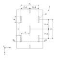
- Fig. 2 is a plan view diagrammatically showing the light extraction layer 2.
- Fig. 3 is a cross-sectional view diagrammatically showing the light extraction layer 2.
- Fig. 4 is a cross-sectional view diagrammatically showing the light extraction portion 21.
- the size and density of the internal space affect the haze value.
- the size of the internal space (length M, width W: see Figures 2 to 4) is, for example, preferably 10 ⁇ m or more and 500 ⁇ m or less in length M, and 1 ⁇ m or more and 100 ⁇ m or less in width W. From the viewpoint of the light extraction efficiency of the light extraction layer 2, it is preferable that the height H is 1 ⁇ m or more and 100 ⁇ m or less. It is preferable that the multiple internal spaces are distributed discretely and uniformly, and for example, as shown in Figure 2, it is preferable to arrange them periodically.
- the pitch Px is, for example, preferably 10 ⁇ m or more and 500 ⁇ m or less
- the pitch Py is, for example, preferably 10 ⁇ m or more and 500 ⁇ m or less.
- the interval E in Figure 2 is the interval between the multiple internal spaces in the X direction.
- the interval D in Figure 2 is the interval between the multiple internal spaces in the Y direction.
- the refractive index of the adhesive layer 3 is preferably approximately the same as that of the light guide layer 1, and is preferably, for example, 1.45 or more and 1.60 or less.
- the adhesive layer 3 is disposed between the light guide layer 1 and the light extraction layer 2.
- the ratio of the thickness of the adhesive layer 3 to the thickness t1 of the laminated film 10 can be 10% or more, and preferably 15% or more, 20% or more. There is no particular upper limit, but it is, for example, 50% or less, 40% or less.
- ⁇ First Modification> 5 is a schematic cross-sectional view of a laminated film 10 according to a first modification.
- the laminated film 10 according to the first modification is different from the above-described embodiment in that light from a light source 50 can be further incident through an end 2a of the light extraction layer 2.
- light from the light source 50 can be incident not only through the light incident surface 1b but also through the end 2a of the light extraction layer 2, thereby increasing the efficiency with which light from the light source 50 is incident on the laminated film 10.
- the light source 50 is disposed on the light incident surface 1b. Light from the light source 50 can enter the laminate film 10 through the light incident surface 1b and can also enter the laminate film 10 through the end 2a of the light extraction layer 2.
- the light source 50 is fixed to either the light guide layer 1 or the light extraction layer 2 by an adhesive or the like.
- the end 2a of the light extraction layer 2 is the end located closest to the light source 50 among the multiple ends of the light extraction layer 2.
- the light L1 from the light source 50 corresponds to the light that enters the laminate film 10 through the light incident surface 1b.
- the light L2 from the light source 50 corresponds to the light that enters the laminate film 10 through the end 2a of the light extraction layer 2.
- the light extraction layer 2 may be disposed in contact with the light source 50. By disposing the light extraction layer 2 in contact with the light source 50, it is possible to reduce light loss caused by light from the light source 50 leaking out without entering the light extraction layer 2, and to increase the efficiency with which light from the light source 50 enters the light extraction layer 2.
- ⁇ Second Modification> 6 is a schematic cross-sectional view of a laminated film 10 according to a second modification.
- the laminated film 10 according to the second modification is different from the above-mentioned embodiment in that it has a pattern layer 4 disposed between the light guide layer 1 and the light extraction layer 2, and includes a first portion 401 having a lower refractive index than the light guide layer 1, and a second portion 402 having a higher refractive index than the first portion 401.
- the laminated film 10 according to the second modification can improve the uniformity of the luminance of the illumination light by the laminated film 10 according to the second modification by having the pattern layer 4.
- the pattern layer 4 may be configured so that the area of the second portion 402 increases as it moves away from the light incident surface.
- the pattern layer 4 can be an optical coupling layer disclosed in WO 2022/025067.
- the entire disclosure of WO 2022/025067 is incorporated herein by reference.
- the first part 401 may be a low refractive index layer or an air cavity.
- the second part 402 may be made of a material having a refractive index approximately the same as that of the light guide layer 1 or the adhesive layer 3.
- the refractive index of the low refractive index layer is preferably, for example, 1.25 or less, more preferably 1.20 or less, and even more preferably 1.15 or less.
- the low refractive index layer is preferably a solid, and the refractive index is preferably, for example, 1.05 or more.
- the difference between the refractive index of the light guide layer 1 and the refractive index of the low refractive index layer is preferably 0.20 or more, more preferably 0.23 or more, and even more preferably 0.25 or more.
- the low refractive index layer having a refractive index of 1.25 or less can be formed, for example, using a porous material.
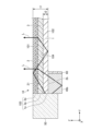
- the tapered member 40 has a bottom surface 41 for stacking on the upper surface 104 of the light guide layer 1, a light incident surface 42 for receiving the light L from the light source 50, and an inclined surface 43 for reflecting the light L incident on the tapered member 40 from the light source 50 and directing it to the light guide layer 1 side.
- the inclined surface 43 can control the direction of the light incident on the inclined surface 43 at an angle less than the critical angle.
- the inclined surface 43 may be a flat surface or a curved surface.
- the curved surface of the inclined surface 43 may be a part of a spherical surface or a part of an aspherical surface. Examples of aspherical surfaces include a parabolic surface.
- the tapered member 40 has a tapered shape that becomes thinner as it moves away from the light source 50.
- the tapered member 40 can be made of a resin or glass material that has a transmittance for the light L from the light source 50.
- the resin material can be an acrylic resin or the like.
- the transmittance here is preferably 60% or more.
- the laminated film 10 may have multiple tapered members 40.
- the laminated film 10 may have one tapered member 40 that has a length that allows light from each of the multiple light sources 50 to enter in the direction in which the multiple light sources 50 are arranged.
- the tapered member 40 can use the "optical incoupling element" disclosed in WO 2022/030544. The entire disclosure of WO 2022/030544 is incorporated herein by reference.
- the tapered member 40 may be any member capable of controlling the reflection direction of light L incident at an angle less than the critical angle, and may be, for example, a diffraction grating or a directional layer including an optical cavity.
- the directional layer may be formed, for example, by laminating a film on which an air cavity pattern is formed to another film.
- the directional layer may be, for example, the "optical incoupling tape" disclosed in WO 2022/030543. The entire disclosure of WO 2022/030543 is incorporated herein by reference.
- ⁇ Fourth Modification> 8 is a schematic cross-sectional view of a laminated film 10 according to a fourth modification.
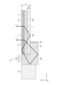
- the laminated film 10 according to the fourth modification is different from the above-described embodiment in that, in a plan view, a prism member 40a is disposed on the light incident surface 1b and serves as a light incident member that causes light from a light source 50 to enter the light guide layer.
- the laminated film 10 can increase the incidence efficiency of light L from the light source 50.
- the prism member 40a has a bottom surface 41a for stacking on the upper surface 104 of the light guide layer 1, and a light incident surface 42a through which light L from the light source 50 is incident.
- the light source 50 and the prism member 40a may be integrally configured by arranging the light exit surface 50a of the light source 50 and the light incident surface 42a of the prism member 40a so that they are in contact with each other. By integrally configuring the light source 50 and the prism member 40a, it is possible to reduce interfacial reflection between the light source 50 and the prism member 40a and reduce light loss, thereby increasing the light incidence efficiency.
- the prism member 40a can be made of a resin or glass material that has a transmittance for the light L from the light source 50.
- the resin material can be an acrylic resin or the like.
- the transmittance here is preferably 60% or more.
- the prism member 40a is disposed on the light incident surface 1b.
- the prism member 40a may be adhered to the light incident surface 1b with an adhesive or the like. From the viewpoint of increasing the efficiency of incidence of light L into the laminated film 10, it is preferable that the distance between the light extraction layer 2 and the prism member 40a is short, and it is more preferable that the light extraction layer 2 and the prism member 40a are in contact with each other.
- the laminated film 10 may have multiple prism members 40a.
- the laminated film 10 may have one prism member 40a that has a length that allows light from each of the multiple light sources 50 to enter in the direction in which the multiple light sources 50 are arranged.
- ⁇ Fifth Modification> 9 is a schematic cross-sectional view of a laminated film 10 according to a fifth modified example.
- the laminated film 10 according to the fifth modified example differs from the above-described embodiment in that the laminated film 10 according to the fifth modified example has a first light-transmitting member 40b as a light incident member that is disposed on the light incident surface 1b in a plan view and causes light from the light source 50 to enter the light guide layer.
- the laminated film 10 can increase the incidence efficiency of the light L from the light source 50.
- the first light-transmitting member 40b is a rectangular parallelepiped member.
- the first light-transmitting member 40b can be disposed on the light incident surface 1b and between the end 2a of the light extraction layer 2 and the light exit surface 50a of the light source 50. After the light L from the light source 50 enters the inside of the first light-transmitting member 40b, a part of it is totally reflected by the upper surface of the first light-transmitting member 40b and enters the inside of the laminated film 10 through the end 2a of the light extraction layer 2, the end 3a of the adhesive layer 3, or the light incident surface 1b.
- the other part of the light L that entered the inside of the first light-transmitting member 40b enters the inside of the laminated film 10 through the end 2a, the end 3a, or the light incident surface 1b without being totally reflected by the upper surface of the first light-transmitting member 40b.
- the first light-transmitting member 40b is preferably arranged in contact with the end portion 2a and in contact with the light exit surface 50a.
- the first light-transmitting member 40b may be adhered to the light entrance surface 1b with an adhesive or the like.
- the positions of the end 2a and the end 3a may be misaligned in the Y direction.
- the first translucent member 40b is arranged so as to contact either the end 2a or the end 3a, a gap is created between the other of the end 2a or the end 3a and the first translucent member 40b.
- the light L from the light source 50 is reflected at the interface in this gap, causing a loss of light incident on the laminated film 10. Therefore, it is preferable that the first translucent member 40b is arranged while being pressed against at least one of the end 2a and the end 3a.
- the first light-transmitting member 40b can be made of a resin or glass material that has a transmittance for the light L from the light source 50.
- the resin material can be an acrylic resin or the like.
- the transmittance here is preferably 60% or more.
- the laminated film 10 may have multiple first light-transmitting members 40b.
- the laminated film 10 may have one first light-transmitting member 40b that has a length that allows light from each of the multiple light sources 50 to enter in the direction in which the multiple light sources 50 are arranged.
- the laminated film 10 may further include a reflective portion 60 disposed on the side of the first translucent member 40b opposite the side on which the light source 50 is located.
- the reflective portion 60 may be a reflective sheet disposed on the surface of the first translucent member 40b opposite the side on which the light source 50 is located.
- the reflective sheet is a sheet-like member that includes a reflective surface, and is fixed by being attached to the surface of the first translucent member 40b opposite the side on which the light source 50 is located.
- the reflecting portion 60 is not limited to a reflecting sheet.
- the reflecting portion 60 may be a reflecting plate in which a reflecting film is formed on a plate-like member.
- the reflecting film may be made of a metal material such as aluminum.
- the reflecting portion 60 may also be formed by applying a metal material by spraying or the like to the surface of the first translucent member 40b opposite the side where the light source 50 is located.
- the laminated film 10 reflects the light L from the light source 50 incident on the first translucent member 40b at the reflecting portion 60, thereby reducing the amount of light L transmitted through the surface opposite to the side where the light source 50 is located and emitted to the outside of the first translucent member 40b. This reduces light loss and increases the efficiency with which the light L from the light source 50 is incident on the laminated film 10.
- the reflecting portion 60 can be easily positioned on the first translucent member 40b.
- ⁇ Sixth Modification> 10 is a schematic cross-sectional view of a laminated film 10 according to a sixth modified example.
- the laminated film 10 according to the sixth modified example differs from the above-described embodiment in that at least a part of the first surface 101, which is the surface of the light extraction layer 2 on the side opposite to the side where the light guide layer 1 is disposed, has a light incident surface 2b.
- the first surface 101 which is the surface of the light extraction layer 2 on the side opposite to the side where the light guide layer 1 is disposed, has a light incident surface 2b.
- the laminated film 10 has a first translucent member 40b.
- the first translucent member 40b is disposed on the light incident surface 2b.
- the area of the light incident surface 2b corresponds to the area of the first surface 101 that faces the first translucent member 40b.
- the first translucent member 40b may be adhered to the light incident surface 2b with an adhesive or the like.
- the light source 50 is arranged so that the light emission surface 50a faces the first light-transmitting member 40b and also faces the end surface 103.
- the end surface 103 is a surface that is composed of the end surface 1a of the light-guiding layer 1, the end surface 2a of the light extraction layer 2, and the end surface 3a of the adhesive layer 3.
- the portion of the light that enters the inside of the first translucent member 40b is totally reflected by the upper surface of the first translucent member 40b, and then enters the inside of the laminated film 10 through the light incident surface 1b.
- the other portion of the light L that enters the inside of the first translucent member 40b enters the inside of the laminated film 10 through the light incident surface 1b without being totally reflected by the upper surface of the first translucent member 40b.
- the light exit surface 50a be arranged in contact with the first translucent member 40b and also in contact with the end surface 103.
- end 1a, end 2a, and end 3a may be shifted from each other in the Y direction.
- the light source 50 is arranged so that the light exit surface 50a contacts one of end 1a, end 2a, or end 3a, a gap is created between the other end and the light exit surface 50a.
- the light L from the light source 50 is reflected at the interface at these gaps, causing a loss of light incident on the laminated film 10. Therefore, it is preferable that the light source 50 is arranged while pressing the light exit surface 50a against at least one of end 1a, end 2a, and end 3a.
- the gap between each of end 1a, end 2a, and end 3a and the light exit surface 50a can be reduced, and the efficiency of incidence of light L from the light source 50 into the laminated film 10 can be increased.
- the laminated film 10 may have multiple first light-transmitting members 40b.
- the laminated film 10 may have one first light-transmitting member 40b that has a length that allows light from each of the multiple light sources 50 to enter in the direction in which the multiple light sources 50 are arranged.
- the gap between each of the end 1a, the end 2a, and the end 3a and the second translucent member 40c can be reduced, and the efficiency of incidence of the light L from the light source 50 on the laminated film 10 can be increased.
- the laminated film 10 may have multiple second light-transmitting members 40c.
- the laminated film 10 may have one second light-transmitting member 40c that has a length that allows light from each of the multiple light sources 50 to enter in the direction in which the multiple light sources 50 are arranged.
Landscapes
- Physics & Mathematics (AREA)
- Engineering & Computer Science (AREA)
- Optics & Photonics (AREA)
- General Physics & Mathematics (AREA)
- General Engineering & Computer Science (AREA)
- Spectroscopy & Molecular Physics (AREA)
- Microelectronics & Electronic Packaging (AREA)
- Manufacturing & Machinery (AREA)
- Planar Illumination Modules (AREA)
- Laminated Bodies (AREA)
Abstract
Description
<実施形態に係る積層フィルム10の全体構成例>
図1は、第1実施形態に係る積層フィルム10の一例を模式的に示す断面図である。図1に示す例では、積層フィルム10は、複数の層が積層される積層フィルムである。積層フィルム10は、積層方向(Z方向)に沿う端面103と、端面103に交差し、光源50からの光Lを入射させる光入射面1bと、光入射面1bを通して入射される光Lを導光する導光層1と、導光層1により導光される光Lを抽出可能な光抽出部21を含む光抽出層2と、を有する。
導光層1は、両面が平坦なフィルムから形成可能である。導光層1に用いる材料は、光吸収係数が低いものが好ましい。例えば、導光層1に用いる材料として、PMMA(Poly Methyl Methacrylate)等のアクリル系フィルム、COP(Cyclo Olefin Polymer)等のシクロオレフィン系フィルム、PET(Polyethylene Terephthalate)等のポリエチレン系フィルム、ポリカーボネート系フィルム等を使用できる。
図1に加え、図2~4をさらに参照して、光抽出層2の構成の一例について説明する。図2は、光抽出層2を模式的に示す平面図である。図3は、光抽出層2を模式的に示す断面図である。図4は、光抽出部21を模式的に示す断面図である。
粘接着層3には、アクリル系、ポリエステル系等の粘着剤および接着剤の少なくとも一方を適宜選択できる。粘接着層3の屈折率は、導光層1と同程度であることが好ましく、例えば1.45以上1.60以下が好ましい。
以下、様々な変形例について説明する。なお、既に説明した実施形態と同一の名称、符号については、同一もしくは同質の部材又は構成部を示しており、詳細説明を適宜省略する。
図5は、第1変形例に係る積層フィルム10の模式的断面図である。第1変形例に係る積層フィルム10は、光抽出層2の端部2aを通して、光源50からの光をさらに入射可能である点が、上述した実施形態と異なる。第1変形例では、光入射面1bだけでなく、光抽出層2の端部2aからも入射可能にすることで、光源50からの光の積層フィルム10への入射効率を高くすることができる。
図6は、第2変形例に係る積層フィルム10の模式的断面図である。第2変形例に係る積層フィルム10は、導光層1と光抽出層2との間に配置され、導光層1よりも屈折率が低い第1部分401と、第1部分401よりも屈折率が高い第2部分402と、を含むパターン層4を有する点が、上述した実施形態と異なる。第2変形例に係る積層フィルム10は、パターン層4を有することで、第2変形例に係る積層フィルム10による照明光の輝度の均一性を向上させることができる。パターン層4は光入射面から離れるにつれて第2部分402の面積が多くなるように構成されてもよい。
図7は、第3変形例に係る積層フィルム10の模式的断面図である。第3変形例に係る積層フィルム10は、平面視において、光入射面1bに配置され、光源50からの光を導光層に入射させる光入射部材としてのテーパ部材40を有する点が、上述した実施形態と異なる。積層フィルム10は、テーパ部材40を有することで、光源50からの光Lの入射効率を高くすることができる。
図8は、第4変形例に係る積層フィルム10の模式的断面図である。第4変形例に係る積層フィルム10は、平面視において、光入射面1bに配置され、光源50からの光を導光層に入射させる光入射部材としてのプリズム部材40aを有する点が、上述した実施形態と異なる。積層フィルム10は、プリズム部材40aを有することで、光源50からの光Lの入射効率を高くすることができる。
図9は、第5変形例に係る積層フィルム10の模式的断面図である。第5変形例に係る積層フィルム10は、平面視において、光入射面1bに配置され、光源50からの光を導光層に入射させる光入射部材としての第1透光部材40bを有する点が、上述した実施形態と異なる。積層フィルム10は、第1透光部材40bを有することで、光源50からの光Lの入射効率を高くすることができる。
図10は、第6変形例に係る積層フィルム10の模式的断面図である。第6変形例に係る積層フィルム10は、導光層1が配置される側とは反対側における光抽出層2の表面である第1面101の少なくとも一部に光入射面2bを有する点が、上述した実施形態と異なる。第1面101の少なくとも一部を光入射面2bとすることで、光源50からの光Lの積層フィルム10への入射効率を高くすることができる。
図11は、第7変形例に係る積層フィルム10の模式的断面図である。第7変形例では、光入射部材としての第2透光部材40cは、一部が光入射面2bに向き合い、且つ他の一部が端面103に向き合うように配置される点が、第6変形例と異なる。第2透光部材40cは、その一部が光入射面2bに向き合うとともに、他の一部が端面103に向き合う。第2透光部材40cを有することで、光源50からの光Lの積層フィルム10への入射効率を高くすることができる。
図12は、第8変形例に係る積層フィルム10の模式的断面図である。第8変形例に係る積層フィルム10は、光抽出層2が配置される側とは反対側における導光層1の表面である第2面102の少なくとも一部を光入射面2bとする点が、第6変形例と異なる。第8変形例の作用効果は、第6変形例と同様である。
図13は、第9変形例に係る積層フィルム10の模式的断面図である。第9変形例に係る積層フィルム10は、光抽出層2が配置される側とは反対側における導光層1の表面である第2面102の少なくとも一部を光入射面2bとする点が、第7変形例と異なる。第9変形例の作用効果は、第7変形例と同様である。
以下、実施例および比較例について説明する。但し、本発明は、これらの例に何ら限定されない。なお、以下に示す説明では、説明を分かりやすくするために、比較例1~3においても、図1に示した積層フィルム10と実質的に同じ構成には、図1に示した符号と同じ符号を便宜的に用いる場合がある。
(発光度合の評価)
実施例および比較例に係る積層フィルム内に光源50から光を入射させて、光抽出層側から光を取り出した。取り出された光について、目視で発光輝度を評価した。以下に、発光度合いの評価指標である「A」~[D]それぞれの定義を示す。
A:非常に良好(輝度が非常に高い)。
B:良好(輝度が高い)。
C:やや良好(輝度がやや高い)。
D:不良(輝度が低い)。
実施例および比較例に係る積層フィルムの可撓性を官能評価した。以下に可撓性の評価指標である「A」~「D」それぞれの定義を示す。
A:非常に良好(長尺の場合にロール巻き取りが可能なほど柔らかい)。
B:良好(Aよりも劣るが長尺の場合にロール巻き取りが可能なほど柔らかい)。
C:やや良好(Bより劣るが長尺の場合にロール巻き取りが可能なほど柔らかい)。
D:不良(長尺の場合にロール巻き取りが難しい)
実施例および比較例に係る積層フィルムへの光入射安定性を官能評価した。以下に光入射安定性の評価指標である「A」~「C」の定義を示す。
A:容易に安定な光入射が可能
B:安定な光入射が可能
C:安定な光入射が困難
以下、実施例1に係る積層フィルムの条件を示す。
・導光層1:材質をアクリル樹脂、厚みを130μmとした。
・粘接着層3:材質を樹脂(CS9864)、厚みを100μmとした。
・光抽出層2の基材フィルム:材質をアクリル樹脂、厚みを30μmとした。
・光抽出層2の粘着剤:材質をポリエステル樹脂、厚みを7μmとした。
・光抽出層2の凹凸フィルム:材質をアクリル樹脂、厚みを128μmとした。
・積層フィルム10全体の厚みを395μmとした。
・光入射面1bにおける導光層1の端部1aから光抽出層2の端部2aまでの長さを50mmとした。
・光源50からの光を、光入射面1bおよび端面103を通して積層フィルムの内部に入射させた。
光入射面1bにテーパ部材40を配置(第3変形例)し、テーパ部材40を介して光源50からの光を、光入射面1bおよび端面103のそれぞれを通して積層フィルムに入射させた点以外は、実施例1と同様とした。
光入射面1bにテーパ部材40を配置(第3変形例)し、テーパ部材40を介して光源50からの光を、光入射面1bのみを通して積層フィルムに入射させた点以外は、実施例1と同様とした。
・導光層1の厚みを170μmとした。
・光抽出層2の厚みを725μmとした。
・積層フィルム全体の厚みを995μmとした。
・上記の点以外は、実施例1と同様とした。
・導光層1の厚みを170μmとした。
・光抽出層2の厚みを725μmとした。
・積層フィルム全体の厚みを995μmとした。
・上記の点以外は、実施例2と同様とした。
・導光層1の厚みを170μmとした。
・光抽出層2の厚みを725μmとした。
・積層フィルム全体の厚みを995μmとした。
・上記の点以外は、実施例3と同様とした。
・導光層1の厚みを30μmとした。
・積層フィルム全体の厚みを295μmとした。
・上記の点以外は、実施例1と同様とした。
・導光層1の厚みを30μmとした。
・積層フィルム全体の厚みを295μmとした。
・上記の点以外は、実施例2と同様とした。
光入射部材としてプリズム部材40a(第4変形例)を用いた点以外は、実施例1と同様とした。
光入射部材として第1透光部材40b(第5変形例)を用いた点以外は、実施例1と同様とした。
非重複領域を「無」とするとともに、光入射部材として第1透光部材40b(第6変形例)を用いた点以外は、実施例1と同様とした。ここで、非重複領域とは、平面視において、光抽出層と導光層とが重ならない導光層の領域を意味する。
非重複領域を「無」とするとともに、光入射部材として第2透光部材40c(第7変形例)を用いた点以外は、実施例1と同様とした。
光源50からの光を、端面103を通して積層フィルムに入射した点以外は実施例1と同様とした。
非重複領域を「無」とし、光源50からの光を、端面103を通して積層フィルムに入射した点以外は実施例1と同様とした。
導光層の厚みを1000μm、粘接着層の厚みを50μm、光抽出層の厚みを165μm、積層フィルム全体の厚みを1215μmとし、かつ光源50からの光を、端面103を通して積層フィルムに入射した点以外は、実施例1と同様とした。

実施形態に係る積層フィルム10は、積層フィルム10の一方側に配置され、導光層1よりも屈折率が低い低屈折率層を有してもよい。低屈折率層は、屈折率が1.30以下であることが好ましい。被着体に配置された状態等における積層フィルム10の存在感を低減する観点では、積層フィルム10における低屈折率層が配置された側とは反対側における積層フィルム10の表面から、低屈折率層が配置された側における積層フィルム10の表面までの全体厚みは、1500μm以下であることが好ましい。
<1> 複数の層が積層される積層フィルムであって、積層方向に沿う端面と、前記端面に交差し、光源からの光を入射させる光入射面と、前記光入射面を通して入射される光を導光する導光層と、前記導光層により導光される光を抽出可能な光抽出部を含む光抽出層と、を有し、前記導光層が配置される側とは反対側における前記光抽出層の表面である第1面と、前記光抽出層が配置される側とは反対側における前記導光層の表面である第2面と、の間の厚みは1000μm以下である、積層フィルムである。
<2> 前記光入射面に配置され、前記光源からの光を入射させる光入射部材をさらに有する、前記<1>に記載の積層フィルムである。
<3> 前記光入射部材は、一部が前記光入射面に向き合い、且つ他の一部が前記端面に向き合うように配置される、前記<2>に記載の積層フィルムである。
<4> 前記光入射部材における前記光源が位置する側とは反対側に配置される反射部をさらに含む、前記<3>に記載の積層フィルムである。
<5> 前記反射部は、前記光入射部材の前記光源が位置する側とは反対側の面に配置される反射シートである、前記<4>に記載の積層フィルムである。
<6> 前記導光層の厚みは、30μm以上である、前記<1>または前記<2>に記載の積層フィルムである。
<7> 前記導光層と前記光抽出層との間に配置され、前記導光層よりも屈折率が低い第1部分と、前記第1部分よりも屈折率が高い第2部分と、を含むパターン層を有する、前記<1>から前記<6>のいずれか1つに記載の積層フィルムである。
<8> 前記光抽出層の端部は、平面視において、前記導光層の端部よりも前記導光層の内側に位置し、前記光入射面は、平面視において、前記光抽出層と前記導光層とが重ならない前記導光層の領域に位置する、前記<1>から前記<7>のいずれか1つに記載の積層フィルムである。
<9> 前記光抽出層は、前記導光層における前記光源が配置される側に配置されている、前記<8>に記載の積層フィルムである。
<10> 前記光抽出層の端部を通して前記光源からの光をさらに入射可能である、前記<8>または前記<9>に記載の積層フィルムである。
<11> 前記光抽出層は、前記光源と接触して配置されている、前記<10>に記載の積層フィルムである。
<12> 巻取り可能に長尺に形成されている、前記<1>から前記<11>のいずれか1つに記載の積層フィルムである。
1a 端部
1b、2b 光入射面
101 第1面
102 第2面
103 端面
104 上面
2 光抽出層
2a 端部
21 光抽出部
3 粘接着層
3a 端部
4 パターン層
401 第1部分
402 第2部分
10 積層フィルム
40 テーパ部材(光入射部材の一例)
41 底面
42 光入射面
43 傾斜面
40a プリズム部材(光入射部材の一例)
41a 底面
42a 光入射面
40b 第1透光部材(光入射部材の一例)
40c 第2透光部材(光入射部材の一例)
41c 第1対向面
42c 第2対向面
50 光源
50a 光出射面
60 反射部
L、L1、L2 光
t1 積層フィルムの厚み
t2 導光層の厚み
D Y方向における複数の内部空間同士の間隔
E X方向における複数の内部空間同士の間隔
M 長さ
Px X方向における複数の内部空間のピッチ
Py Y方向における複数の内部空間のピッチ
H 高さ
W 幅
θa、θb 角度
Claims (12)
- 複数の層が積層される積層フィルムであって、
積層方向に沿う端面と、
前記端面に交差し、光源からの光を入射させる光入射面と、
前記光入射面を通して入射される光を導光する導光層と、
前記導光層により導光される光を抽出可能な光抽出部を含む光抽出層と、を有し、
前記導光層が配置される側とは反対側における前記光抽出層の表面である第1面と、前記光抽出層が配置される側とは反対側における前記導光層の表面である第2面と、の間の厚みは1000μm以下である、積層フィルム。 - 前記光入射面に配置され、前記光源からの光を入射させる光入射部材をさらに有する、請求項1に記載の積層フィルム。
- 前記光入射部材は、一部が前記光入射面に向き合い、且つ他の一部が前記端面に向き合うように配置される、請求項2に記載の積層フィルム。
- 前記光入射部材における前記光源が位置する側とは反対側に配置される反射部をさらに含む、請求項3に記載の積層フィルム。
- 前記反射部は、前記光入射部材の前記光源が位置する側とは反対側の面に配置される反射シートである、請求項4に記載の積層フィルム。
- 前記導光層の厚みは、30μm以上である、請求項1または請求項2に記載の積層フィルム。
- 前記導光層と前記光抽出層との間に配置され、前記導光層よりも屈折率が低い第1部分と、前記第1部分よりも屈折率が高い第2部分と、を含むパターン層を有する、請求項1または請求項2に記載の積層フィルム。
- 前記光抽出層の端部は、平面視において、前記導光層の端部よりも前記導光層の内側に位置し、
前記光入射面は、平面視において、前記光抽出層と前記導光層とが重ならない前記導光層の領域に位置する、請求項1に記載の積層フィルム。 - 前記光抽出層は、前記導光層における前記光源が配置される側に配置されている、請求項8に記載の積層フィルム。
- 前記光抽出層の端部を通して前記光源からの光をさらに入射可能である、請求項8に記載の積層フィルム。
- 前記光抽出層は、前記光源と接触して配置されている、請求項10に記載の積層フィルム。
- 巻取り可能に長尺に形成されている、請求項1または請求項2に記載の積層フィルム。
Priority Applications (3)
| Application Number | Priority Date | Filing Date | Title |
|---|---|---|---|
| KR1020257038606A KR20260021607A (ko) | 2023-06-05 | 2024-05-17 | 적층 필름 |
| CN202480036762.9A CN121443888A (zh) | 2023-06-05 | 2024-05-17 | 层叠膜 |
| EP24819128.0A EP4722582A1 (en) | 2023-06-05 | 2024-05-17 | Laminated film |
Applications Claiming Priority (2)
| Application Number | Priority Date | Filing Date | Title |
|---|---|---|---|
| JP2023092332A JP2024174482A (ja) | 2023-06-05 | 2023-06-05 | 積層フィルム |
| JP2023-092332 | 2023-06-05 |
Publications (1)
| Publication Number | Publication Date |
|---|---|
| WO2024252895A1 true WO2024252895A1 (ja) | 2024-12-12 |
Family
ID=93795203
Family Applications (1)
| Application Number | Title | Priority Date | Filing Date |
|---|---|---|---|
| PCT/JP2024/018294 Ceased WO2024252895A1 (ja) | 2023-06-05 | 2024-05-17 | 積層フィルム |
Country Status (6)
| Country | Link |
|---|---|
| EP (1) | EP4722582A1 (ja) |
| JP (1) | JP2024174482A (ja) |
| KR (1) | KR20260021607A (ja) |
| CN (1) | CN121443888A (ja) |
| TW (1) | TW202448689A (ja) |
| WO (1) | WO2024252895A1 (ja) |
Citations (9)
| Publication number | Priority date | Publication date | Assignee | Title |
|---|---|---|---|---|
| WO2011124765A1 (en) | 2010-04-06 | 2011-10-13 | Kari Rinko | Laminate structure with embedded cavities and related method of manufacture |
| WO2011127187A1 (en) | 2010-04-06 | 2011-10-13 | Modilis Holding Llc | Internal cavity optics |
| WO2019087118A1 (en) | 2017-11-01 | 2019-05-09 | Nitto Denko Corporation | Light distribution structure and element, related method and uses |
| JP2019106330A (ja) * | 2017-12-14 | 2019-06-27 | 日東電工株式会社 | 光学部材および導光システム |
| WO2019182091A1 (ja) | 2018-03-22 | 2019-09-26 | 日東電工株式会社 | 光学デバイス |
| WO2022025067A1 (ja) | 2020-07-28 | 2022-02-03 | 日東電工株式会社 | 照明装置用導光部材、照明装置および建築部材 |
| WO2022030544A1 (en) | 2020-08-06 | 2022-02-10 | Nitto Denko Corporation | Light incoupling element, related method and uses |
| WO2022030543A1 (en) | 2020-08-06 | 2022-02-10 | Nitto Denko Corporation | Light incoupling tape, related method and uses |
| JP2023092332A (ja) | 2021-12-21 | 2023-07-03 | 株式会社セガ | プログラム及び情報処理装置 |
-
2023
- 2023-06-05 JP JP2023092332A patent/JP2024174482A/ja active Pending
-
2024
- 2024-05-17 KR KR1020257038606A patent/KR20260021607A/ko active Pending
- 2024-05-17 EP EP24819128.0A patent/EP4722582A1/en active Pending
- 2024-05-17 WO PCT/JP2024/018294 patent/WO2024252895A1/ja not_active Ceased
- 2024-05-17 CN CN202480036762.9A patent/CN121443888A/zh active Pending
- 2024-05-22 TW TW113118928A patent/TW202448689A/zh unknown
Patent Citations (9)
| Publication number | Priority date | Publication date | Assignee | Title |
|---|---|---|---|---|
| WO2011124765A1 (en) | 2010-04-06 | 2011-10-13 | Kari Rinko | Laminate structure with embedded cavities and related method of manufacture |
| WO2011127187A1 (en) | 2010-04-06 | 2011-10-13 | Modilis Holding Llc | Internal cavity optics |
| WO2019087118A1 (en) | 2017-11-01 | 2019-05-09 | Nitto Denko Corporation | Light distribution structure and element, related method and uses |
| JP2019106330A (ja) * | 2017-12-14 | 2019-06-27 | 日東電工株式会社 | 光学部材および導光システム |
| WO2019182091A1 (ja) | 2018-03-22 | 2019-09-26 | 日東電工株式会社 | 光学デバイス |
| WO2022025067A1 (ja) | 2020-07-28 | 2022-02-03 | 日東電工株式会社 | 照明装置用導光部材、照明装置および建築部材 |
| WO2022030544A1 (en) | 2020-08-06 | 2022-02-10 | Nitto Denko Corporation | Light incoupling element, related method and uses |
| WO2022030543A1 (en) | 2020-08-06 | 2022-02-10 | Nitto Denko Corporation | Light incoupling tape, related method and uses |
| JP2023092332A (ja) | 2021-12-21 | 2023-07-03 | 株式会社セガ | プログラム及び情報処理装置 |
Also Published As
| Publication number | Publication date |
|---|---|
| CN121443888A (zh) | 2026-01-30 |
| JP2024174482A (ja) | 2024-12-17 |
| TW202448689A (zh) | 2024-12-16 |
| EP4722582A1 (en) | 2026-04-08 |
| KR20260021607A (ko) | 2026-02-13 |
Similar Documents
| Publication | Publication Date | Title |
|---|---|---|
| KR20150130810A (ko) | 광원 모듈 및 이를 구비하는 조명 장치 | |
| CN102834745A (zh) | 光学装置和照明装置 | |
| US20230280523A1 (en) | Lighting-device light guide member, lighting device, and building material | |
| US20210181399A1 (en) | Improved light distribution element | |
| KR20100103555A (ko) | 프리즘 구조체를 가진 백라이트 반사기 | |
| JP2026071234A (ja) | 光学インカップリングテープ、これを用いたライトガイド、およびその製造方法 | |
| US20240230978A1 (en) | Light guide member for light emission device and light emission device | |
| JP2014002968A (ja) | 照明装置 | |
| JP2024174482A (ja) | 積層フィルム | |
| US7128443B2 (en) | Light-collimating system | |
| JP5988136B2 (ja) | パネル部材、光学デバイス及び壁材 | |
| JP2025073201A (ja) | 導光フィルム、及び照明装置 | |
| JP2023538261A (ja) | 光偏向テープ、関連する方法および使用 | |
| KR20260021595A (ko) | 적층 필름 및 롤 | |
| WO2025205889A1 (ja) | 導光体、及び照明装置 | |
| TW202613612A (zh) | 導光體及照明裝置 | |
| WO2025205370A1 (ja) | 照明装置 | |
| WO2023276705A1 (ja) | 光学積層体および照明装置 | |
| JP2025153168A (ja) | 賦形フィルム、積層体、導光層付き積層体、照明装置、及び金型 | |
| WO2025205368A1 (ja) | 賦形フィルム、積層体、導光層付き積層体、及び照明装置 | |
| WO2023276836A1 (ja) | 照明装置用導光部材および照明装置 | |
| WO2022244474A1 (ja) | 光学装置 | |
| WO2024101281A1 (ja) | 光学部材、および照明装置 | |
| JP6066564B2 (ja) | 照明装置 |
Legal Events
| Date | Code | Title | Description |
|---|---|---|---|
| 121 | Ep: the epo has been informed by wipo that ep was designated in this application |
Ref document number: 24819128 Country of ref document: EP Kind code of ref document: A1 |
|
| ENP | Entry into the national phase |
Ref document number: 2024819128 Country of ref document: EP Effective date: 20260105 |
|
| WWE | Wipo information: entry into national phase |
Ref document number: 2024819128 Country of ref document: EP |
|
| NENP | Non-entry into the national phase |
Ref country code: DE |
|
| ENP | Entry into the national phase |
Ref document number: 2024819128 Country of ref document: EP Effective date: 20260105 |
|
| ENP | Entry into the national phase |
Ref document number: 2024819128 Country of ref document: EP Effective date: 20260105 |
|
| ENP | Entry into the national phase |
Ref document number: 2024819128 Country of ref document: EP Effective date: 20260105 |
|
| ENP | Entry into the national phase |
Ref document number: 2024819128 Country of ref document: EP Effective date: 20260105 |
|
| ENP | Entry into the national phase |
Ref document number: 2024819128 Country of ref document: EP Effective date: 20260105 |
|
| WWP | Wipo information: published in national office |
Ref document number: 2024819128 Country of ref document: EP |