WO2024252875A1 - 診断センサおよびこれを用いた状態判定システム - Google Patents
診断センサおよびこれを用いた状態判定システム Download PDFInfo
- Publication number
- WO2024252875A1 WO2024252875A1 PCT/JP2024/017986 JP2024017986W WO2024252875A1 WO 2024252875 A1 WO2024252875 A1 WO 2024252875A1 JP 2024017986 W JP2024017986 W JP 2024017986W WO 2024252875 A1 WO2024252875 A1 WO 2024252875A1
- Authority
- WO
- WIPO (PCT)
- Prior art keywords
- sound
- sensor
- vibration
- frequency range
- housing
- Prior art date
- Legal status (The legal status is an assumption and is not a legal conclusion. Google has not performed a legal analysis and makes no representation as to the accuracy of the status listed.)
- Ceased
Links
Images






Classifications
-
- G—PHYSICS
- G01—MEASURING; TESTING
- G01H—MEASUREMENT OF MECHANICAL VIBRATIONS OR ULTRASONIC, SONIC OR INFRASONIC WAVES
- G01H1/00—Measuring characteristics of vibrations in solids by using direct conduction to the detector
- G01H1/12—Measuring characteristics of vibrations in solids by using direct conduction to the detector of longitudinal or not specified vibrations
- G01H1/14—Frequency
-
- G—PHYSICS
- G01—MEASURING; TESTING
- G01H—MEASUREMENT OF MECHANICAL VIBRATIONS OR ULTRASONIC, SONIC OR INFRASONIC WAVES
- G01H1/00—Measuring characteristics of vibrations in solids by using direct conduction to the detector
- G01H1/003—Measuring characteristics of vibrations in solids by using direct conduction to the detector of rotating machines
-
- G—PHYSICS
- G01—MEASURING; TESTING
- G01H—MEASUREMENT OF MECHANICAL VIBRATIONS OR ULTRASONIC, SONIC OR INFRASONIC WAVES
- G01H17/00—Measuring mechanical vibrations or ultrasonic, sonic or infrasonic waves, not provided for in the other groups of this subclass
-
- G—PHYSICS
- G01—MEASURING; TESTING
- G01M—TESTING STATIC OR DYNAMIC BALANCE OF MACHINES OR STRUCTURES; TESTING OF STRUCTURES OR APPARATUS, NOT OTHERWISE PROVIDED FOR
- G01M13/00—Testing of machine parts
-
- G—PHYSICS
- G01—MEASURING; TESTING
- G01M—TESTING STATIC OR DYNAMIC BALANCE OF MACHINES OR STRUCTURES; TESTING OF STRUCTURES OR APPARATUS, NOT OTHERWISE PROVIDED FOR
- G01M3/00—Investigating fluid-tightness of structures
- G01M3/02—Investigating fluid-tightness of structures by using fluid or vacuum
- G01M3/04—Investigating fluid-tightness of structures by using fluid or vacuum by detecting the presence of fluid at the leakage point
- G01M3/24—Investigating fluid-tightness of structures by using fluid or vacuum by detecting the presence of fluid at the leakage point using infrasonic, sonic or ultrasonic vibrations
-
- G—PHYSICS
- G01—MEASURING; TESTING
- G01M—TESTING STATIC OR DYNAMIC BALANCE OF MACHINES OR STRUCTURES; TESTING OF STRUCTURES OR APPARATUS, NOT OTHERWISE PROVIDED FOR
- G01M99/00—Subject matter not provided for in other groups of this subclass
Definitions
- This disclosure relates to a diagnostic sensor and a condition determination system using the same.
- Patent Document 1 proposes a diagnostic sensor that has a vibration sensor and an acoustic emission (hereinafter simply referred to as AE) sensor. Specifically, in this diagnostic sensor, a detection signal is output from the vibration sensor according to the state of the low frequency side, and a detection signal is output from the AE sensor according to the state of the high frequency side. The AE sensor outputs a detection signal according to the elastic waves generated when elastic energy is released.
- AE acoustic emission
- the surface of the mounted member may be rough.
- the AE sensor that detects the state of the high frequency side detects the elastic waves propagated from the mounted member through a solid part, so it is easily affected by the surface roughness of the mounted member, and if the surface of the mounted member is rough, the detection accuracy may be reduced.
- the placement constraints may be large.
- a diagnostic sensor that is attached to a mounted member for use includes a vibration sensor that outputs a vibration detection signal corresponding to vibrations in a first detection frequency range, a sound sensor that outputs a sound detection signal corresponding to sound propagating through space in a second detection frequency range that includes frequencies higher than the first detection frequency range, and a housing that has an accommodation space for accommodating the vibration sensor and the sound sensor and has a through hole formed on one side that faces the mounted member when attached to the mounted member for guiding sound.
- the diagnostic sensor is configured to have a vibration sensor and a sound sensor, and the state of the high frequency side is detected by the sound sensor.
- the sound sensor then outputs a sound detection signal corresponding to the sound propagating through space. Therefore, compared to, for example, detecting the state of the high frequency side with an AE sensor, the sound sensor outputs a sound detection signal corresponding to the sound propagating through space, making it less susceptible to the influence of the surface of the mounted component and reducing placement constraints.
- this diagnostic sensor it is possible to reduce placement constraints while suppressing a decrease in the detection accuracy of the state of the high frequency side.
- the condition determination system includes the above-mentioned diagnostic sensor and a control unit that performs a predetermined process, and the control unit determines the condition of the determination target part using a vibration determination signal based on the vibration detection signal and a sound determination signal based on the sound detection signal.
- FIG. 1 is a schematic diagram of a state determination system according to a first embodiment.
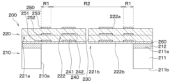
- FIG. 2 is a cross-sectional view showing the configuration of a sound detection element.
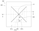
- FIG. 2 is a plan view showing the configuration of a sound detection element.
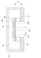
- FIG. 2 is a cross-sectional view showing a configuration of a sound sensor.
- FIG. FIG. 1 is a cross-sectional view of a diagnostic sensor attached to a mounting member.
- FIG. FIG. 1 is a schematic diagram of a machine tool including a mounted component.
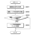
- 5 is a flowchart showing an abnormality determination as a state determination executed by a control unit.
- 5 is a flowchart showing a self-diagnosis determination executed by a control unit.
- FIG. 10 is a flowchart showing a filter setting process executed by a control unit.
- FIG. 11 is a schematic diagram of a state determination system according to a second embodiment.
- FIG. FIG. 13 is a schematic diagram of a state determination system according to a third embodiment.
- FIG. 13 is a cross-sectional view of the vicinity of a sound sensor in a fourth embodiment.
- FIG. 13 is a cross-sectional view of the vicinity of a vibration sensor in a fifth embodiment.
- FIG. 13 is a cross-sectional view of the vicinity of a vibration sensor in a modified example of the fifth embodiment.
- FIG. 13 is a schematic diagram of a state determination system according to a sixth embodiment.
- the state determination system of the first embodiment will be described with reference to the drawings.
- the state determination system of this embodiment is used to detect the state of the determination target part, for example, to determine the state of wear of cutting tools used in cutting and grinding, and to determine the state of cracks, chips, and galling of presses and molding machines.
- the state determination system of this embodiment is also used to determine the state of damage, wear, lubrication state, and the like of bearings, and to determine the state of air leaks and abnormal noises of fans and piping.
- the state determination system of this embodiment is used, for example, for state determination to extract optimal processing conditions when processing a workpiece.
- extracting optimal processing conditions when processing a workpiece means that the determination target part is the workpiece and extracting optimal processing conditions from the state of the workpiece.
- the state determination system is applied to a machine tool having a cutting tool to perform state determination of the cutting tool.
- the state determination system of this embodiment can be used to perform state determination of various determination target parts.
- the state determination system of this embodiment is configured to include a diagnostic sensor 1, a control unit 2, and an alarm unit 3. First, the configuration of the diagnostic sensor 1 will be described.
- the diagnostic sensor 1 includes a vibration sensor 10, a sound sensor 20, a first wiring board 30, a second wiring board 40, and a housing 50.
- a vibration sensor 10 and one sound sensor 20 are provided, but at least one of the vibration sensor 10 and the sound sensor 20 may be provided in multiples.
- the vibration sensor 10 includes a vibration detection element that outputs a vibration detection signal corresponding to the applied vibration.
- the vibration sensor 10 of this embodiment outputs a vibration detection signal corresponding to vibration in a first detection frequency range.
- the first detection frequency range is, for example, 1 Hz to 10 kHz.
- the vibration detection element constituting the vibration sensor 10 is not particularly limited in configuration, but may be, for example, a contact type piezoelectric element, an electromagnetic or electrostatic acceleration detection element, or an angular velocity detection element.
- the vibration detection element may be composed of a plurality of acceleration detection elements so that the first to third axes are the detection axes.
- the vibration detection element When the vibration detection element is composed of an acceleration detection element and an angular velocity detection element, the vibration detection element may be composed of a plurality of acceleration detection elements and angular velocity detection elements so that the first to sixth axes are the detection axes. Furthermore, the vibration sensor 10 also outputs a signal outside the first detection frequency range, but the signal outside the first detection frequency range is a signal with low reliability and is not a signal corresponding to vibration. Therefore, the first detection frequency range in this embodiment can be said to be the range in which a vibration detection signal that meets the required reliability is output.
- the sound sensor 20 includes a sound detection element 200 that outputs a sound detection signal corresponding to the applied sound.
- the sound sensor 20 of this embodiment outputs a sound detection signal corresponding to a sound in the second detection frequency range.
- the second detection frequency range is, for example, 20 Hz to 20 kHz.
- the second detection frequency range includes a higher frequency side than the first detection frequency range, and the sound sensor 20 of this embodiment is configured to be able to detect a state on the higher frequency side than the vibration sensor 10.
- the second detection frequency range of this embodiment includes a superimposed frequency range that overlaps with the first detection frequency range.
- the sound detection element 200 constituting the sound sensor 20 is not particularly limited, but is, for example, configured as a piezoelectric type, electrostatic type, or capacitor type, and is a piezoelectric type in this embodiment.
- the sound sensor 20 also outputs a signal outside the second detection frequency range, but the signal outside the second detection frequency range is a signal with low reliability and is not a signal corresponding to the sound. For this reason, the second detection frequency range of this embodiment can be said to be a range in which a sound detection signal that meets the required reliability is output.
- the vibration sensor 10 of this embodiment is configured with a vibration detection element packaged
- the sound sensor 20 of this embodiment is configured with a sound detection element packaged.
- the vibration sensor 10 and the sound sensor 20 are arranged on the first and second wiring boards 30, 40 as described below, it is preferable for ease of assembly to be a leadless structure, with pad-like terminals arranged on the outer surface, as a QFN.
- QFN is an abbreviation for Quad Flat Non-leaded Package.
- FIG. 1 shows a schematic diagram of the packaged vibration sensor 10 and sound sensor 20.
- the sound detection element 200 includes a support 210 and a vibration portion 220, and has a rectangular planar shape.
- the support 210 includes a support substrate 211 having one surface 211a and the other surface 211b, and an insulating film 212 formed on the one surface 211a of the support substrate 211.
- the support substrate 211 is made of, for example, a silicon substrate, and the insulating film 212 is made of an oxide film.
- the vibration part 220 is disposed on the support 210.
- a recess 210a is formed in the support 210 to allow the inner edge side of the vibration part 220 to float. Therefore, the vibration part 220 has a configuration including a support region 221a disposed on the support 210, and a floating region 221b that is connected to the support region 221a and floats above the recess 210a.
- the recess 210a in this embodiment has an open end on the vibration part 220 side that is rectangular in plan view. Therefore, the entire floating region 221b has a rectangular plan view.
- slits 230 are formed which penetrate the floating region 221b in the thickness direction.
- the slits 230 are formed so as to divide the floating region 221b into four. More specifically, two slits 230 are formed so as to pass through the center C1 of the floating region 221b and extend toward opposing corners of the floating region 221b.
- the slits 230 extend from each corner of the floating region 221b, which has a rectangular shape in plan view, toward the center C1, and are formed so that the slits 230 intersect at the center C1.
- the floating region 221b is separated into four vibration regions 222 which have an approximately triangular shape in plan view.
- Each vibration region 222 is a cantilever with the end on the support region 221a side as a fixed end and the tip end on the opposite side to the support region 221a as a free end.
- the surface of the vibration region 222 opposite the support 210 is described as one surface 222a of the vibration region 222, and the surface of the vibration region 222 on the support 210 side is described as the other surface 222b of the vibration region 222.
- the vibration region 222 corresponds to a detection unit that outputs a sound detection signal when sound is applied.
- the vibration section 220 is configured to have a piezoelectric film 240 and an electrode film 250 connected to the piezoelectric film 240.
- the piezoelectric film 240 has a lower piezoelectric film 241 and an upper piezoelectric film 242 laminated on the lower piezoelectric film 241.
- the lower piezoelectric film 241 and the upper piezoelectric film 242 are configured using lead-free piezoelectric ceramics such as scandium aluminum nitride (ScAlN) and aluminum nitride (AlN).
- the electrode film 250 is formed at a predetermined location in the vibration region 222 so as to be connected to the piezoelectric film 240, and is made of molybdenum, copper, platinum, titanium, or the like.
- the electrode film 250 includes a lower electrode film 251 formed below the lower piezoelectric film 241, an intermediate electrode film 252 formed between the lower piezoelectric film 241 and the upper piezoelectric film 242, and an upper electrode film 253 formed above the upper piezoelectric film 242.
- the lower electrode film 251 and the intermediate electrode film 252 are disposed so as to face each other with the lower piezoelectric film 241 in between.
- the intermediate electrode film 252 and the upper electrode film 253 are disposed so as to face each other with the upper piezoelectric film 242 in between.
- the vibration region 222 When the vibration region 222 is supported in a cantilever manner as described above, the stress generated when the vibration region 222 (i.e., the piezoelectric film 240) vibrates tends to be greater on the fixed end side where the vibration region 222 is supported than on the free end side. For this reason, the vibration region 222 is divided into a first region R1 where the stress tends to be greater, and a second region R2 where the stress tends to be smaller.
- an electrode film 250 is formed in each of the first region R1 and the second region R2.
- the electrode film 250 formed in the first region R1 and the electrode film 250 formed in the second region R2 are insulated from each other.
- the electrode film 250 formed in the first region R1 is connected to an electrode portion (not shown) via wiring or the like formed in the support region 221a, although this is not shown in the figure.
- the lower electrode film 251, intermediate electrode film 252, and upper electrode film 253 in each vibration region 222 are connected to the electrode portion so that the change in charge in the first region R1 of each vibration region 222 can be output as a single sound detection signal.
- the lower electrode film 251, intermediate electrode film 252, and upper electrode film 253 formed in the second region R2 are not electrically connected to the respective electrode portions and are in a floating state. Therefore, the lower electrode film 251, intermediate electrode film 252, and upper electrode film 253 formed in the second region R2 are not necessarily required, but in this embodiment, they are provided to protect the portions of the lower piezoelectric film 241 and upper piezoelectric film 242 located in the second region R2.
- the vibration section 220 of this embodiment has a base film 260 on which the lower piezoelectric film 241 and the lower electrode film 251 are disposed.
- the piezoelectric film 240 and the electrode film 250 are disposed on the support 210 via the base film 260.
- the other surface 222b of each vibration region 222 is formed of the base film 260.
- the base film 260 is not necessarily required, but is provided to facilitate crystal growth when forming the lower piezoelectric film 241 and the like.
- the base film 260 is made of aluminum nitride or the like.
- the piezoelectric film 240 has a thickness of about 1 ⁇ m, and the base film 260 has a thickness of about several tens of nm. In other words, the base film 260 is made extremely thin compared to the piezoelectric film 240.
- the above is the configuration of the sound detection element 200.
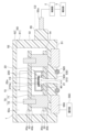
- the sound sensor 20 of this embodiment is packaged as described above, and as shown in FIG. 4, the sound detection element 200 is accommodated in a box-shaped storage box 21 having a storage space 21a.
- the storage box 21 has a wiring board 22 and a lid portion 23 that is arranged on the wiring board 22 and forms the storage space 21a.
- the wiring board 22 is omitted, appropriate wiring is formed so that a QFN structure can be formed, and a communication hole 22a that communicates between the outside and the storage space 21a is formed.
- the sound detection element 200 is arranged on the wiring board 22 via the joint member 24 so that the communication hole 22a is connected to the recess 210a.
- the sound detection element 200 is also electrically connected to the wiring board 22 via a wire or the like not shown.
- the storage space 21a of the sound sensor 20 can be said to be roughly divided into a pressure-receiving surface space V1 surrounded by the recess 210a, and a back space V2 different from the pressure-receiving surface space V1.
- the back space V2 can be said to be the space of the storage space 21a excluding the pressure-receiving surface space V1, and can also be said to be a space that affects the one surface 222a side of the vibration region 222.
- the first wiring board 30 and the second wiring board 40 are each composed of a printed circuit board or the like having one surface 30a, 40a and the other surface 30b, 40b.
- the first wiring board 30 and the second wiring board 40 each have one-surface wiring formed on the one surface 30a, 40a side and other-surface wiring formed on the other surface 30b, 40b side.
- the one-surface wiring and other-surface wiring are appropriately electrically connected via through-hole wiring or the like that penetrates in the thickness direction.
- the sound sensor 20 is arranged on the first surface 30a of the first wiring board 30 and is electrically connected to the sound sensor 20.
- the first wiring board 30 has a communication hole 31 formed therein that penetrates between the first surface 30a and the other surface 30b.
- the sound sensor 20 is arranged on the first surface 30a of the first wiring board 30 so that the communication hole 31 is connected to the communication hole 22a and the recess 210a of the sound sensor 20.
- the second wiring board 40 has the vibration sensor 10 arranged on one surface 40a and is electrically connected to the vibration sensor 10.
- electronic components for reducing noise such as resistors and capacitors, are also appropriately arranged on the first wiring board 30 and the second wiring board 40.
- the housing 50 is made of a resin material, a metal material, or the like, and has an approximately rectangular parallelepiped shape with an outer surface 51, an outer surface 52, and four side surfaces 53 connecting the outer surface 51 and the outer surface 52, and has a storage space 50a inside.
- the outer surface 51 corresponds to one surface.
- the housing 50 is a part that is fixed to a workpiece 300 such as a machine tool as described below, and in this embodiment, the outer surface 51 is provided to face the workpiece 300.
- the part of the housing 50 that faces the workpiece 300 and constitutes the outer surface 51 will be referred to as the facing part 500, and the surface of the facing part 500 opposite the outer surface 51 and that constitutes the storage space 50a will be referred to as the inner surface 54.
- the housing 50 of this embodiment is configured by assembling a bottomed cylindrical case 61 having an opening and a lid 62 that closes the opening of the case 61, and the opposing part 500 is configured by the bottom of the case 61.
- the housing 50 is described as having a substantially rectangular parallelepiped shape with four side surfaces 53, but the external shape of the housing 50 is not particularly limited.
- the housing 50 since the housing 50 is the part that the worker actually handles when the diagnostic sensor 1 is attached to the mounted member 300, it is preferable that the housing 50 has a shape having at least two side surfaces 53 to improve handling.
- the housing 50 has a through hole 510 formed in the facing portion 500 to guide sound from outside the housing 50.
- the through hole 510 is cylindrical with a rectangular cross section.
- the through hole 510 may be tapered (i.e., horn-shaped) so that the width narrows from the outer surface 51 toward the inner surface 54 to make it easier to guide sound.
- the housing 50 has an annular groove 520 formed around the through hole 510 on the outer surface 51 side.
- the annular groove 520 is annular about the central axis of the through hole 510.
- An O-ring is disposed in the groove 520 as a sealing member 530.
- the sealing member 530 may be a square ring having a square cross-sectional shape.
- the groove 520 and sealing member 530 are described here as being annular, the groove 520 and sealing member 530 may be in the shape of a square frame, and the detailed shape is not particularly limited.
- the groove 520 may be a dovetail groove whose width increases as the depth from the outer surface 51 side increases to prevent the sealing member 530 from falling off.
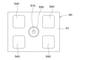
- a magnet 540 is disposed on the outer surface 51 of the housing 50 as an attachment member.
- the magnet 540 is integrated with the housing 50 by press-fitting, screw fastening, insert molding, or the like.
- the magnet 540 is provided on the opposite side of the through hole 510 across the sealing member 530.
- a plurality of magnets 540 are provided, and are provided so as to be rotationally symmetrical with respect to the sealing member 530 in the normal direction (hereinafter simply referred to as the normal direction) to the outer surface 51.
- the magnet 540 can also be said to be provided so as to be rotationally symmetrical with respect to the through hole 510.
- the magnet 540 may also be provided so as to be annular and rotationally symmetrical with respect to the sealing member 530 as the reference, as shown in FIG. 6.
- the magnet 540 may be provided so as to be frame-shaped. In Figure 1, the vertical direction of the paper corresponds to the normal direction.
- the vibration sensor 10, sound sensor 20, first wiring board 30, and second wiring board 40 are housed in the housing space 50a of the housing 50.
- the first wiring board 30 and the second wiring board 40 are stacked at a predetermined distance and fixed to the facing part 500 of the housing 50 via fastening members 70.
- the predetermined distance refers to a distance at which the sound sensor 20 and the second wiring board 40 are not in contact with each other and are separated from each other.
- the fastening members 70 correspond to the fixing members.
- the first wiring board 30 is fixed to the housing 50 by inserting the first fastening member 71 into the outer edge and fastening the first fastening member 71 to the facing portion 500 with the other surface 30b side positioned on the facing portion 500 side of the housing 50.
- the first wiring board 30 is fixed to the housing 50 by four first fastening members 71 arranged to surround the sound sensor 20 in the normal direction.
- the first wiring board 30 is fixed to the housing 50 so that the communication hole 31 and the through hole 510 are connected.
- the communication hole 31 and the through hole 510 are each cylindrical, and the first wiring board 30 is fixed to the housing 50 so that the central axes of the communication hole 31 and the through hole 510 coincide with each other.
- the first fastening member 71 in this embodiment is composed of a screw member with a male-female thread structure in which a male thread structure is formed on one end side and a female thread structure is formed on the other end side, and the one end side is fastened to the opposing part 500.
- the second wiring board 40 is arranged on the first wiring board 30 with the other surface 30b side positioned on the first wiring board 30 side, and the second fastening member 72 is inserted through the outer edge and fastened to the first fastening member 71.
- the second fastening member 72 in this embodiment is composed of a screw member having a male screw structure formed on one end side, and the male screw structure on the one end side is fastened to the female screw structure of the first fastening member 71.
- the first wiring board 30 and the second wiring board 40 in this embodiment are arranged so that they have a portion where the vibration sensor 10 and the sound sensor 20 overlap in the normal direction. And, because four first fastening members 71 are arranged to surround the sound sensor 20, four second fastening members 72 are arranged to surround the vibration sensor 10.
- the fastening member 70 is arranged so as to overlap the magnet 540 in the normal direction. In other words, the fastening member 70 is arranged so as to be located directly above the magnet 540.
- the first wiring board 30 and the second wiring board 40 are fixed to the housing 50 by fastening members 70. Therefore, if the fastening members 70 are made of a conductive metal, the grounds of the first wiring board 30 and the second wiring board 40 can be connected to the housing ground via the fastening members 70.
- a blocking member 80 is disposed between the periphery of the communication hole 31 on the other surface 30b of the first wiring board 30 and the inner surface 54.
- the blocking member 80 is intended to prevent the sound induced from the through hole 510 from leaking out from between the other surface 30b of the first wiring board 30 and the inner surface 54. Since the sound sensor 20 is disposed on the first wiring board 30, it is preferable that the blocking member 80 is made of a material with a low elastic modulus, such as a silicone adhesive, so that vibrations are less likely to be transmitted from the housing 50 to the first wiring board 30.
- the blocking member 80 may also be made of a sheet-like material so as not to block the communication hole 31 or the through hole 510.
- the housing 50 is provided with a connector portion 55 on the side surface 53, and the connector portion 55 has a plurality of terminal portions 55a that are connected to the first wiring board 30 and the second wiring board 40 and are also connected to the control unit 2.
- the connector portion 55 is disposed closer to the outer surface 51 than the center portion C2 in the thickness direction between the outer surface 51 and the other outer surface 52 of the housing 50.
- first and second wiring boards 30, 40 and the terminal portion 55a are electrically connected by lead wires, a flexible substrate, or the like, which are not specifically shown.
- the terminal portion 55a may also be covered by a coating material having environmental resistance.
- a male connector having the terminal portion 55a is described here as an example of the connector portion 55, the connector portion 55 may also be a female connector into which an external terminal portion is inserted.
- Such a diagnostic sensor 1 is mounted on a mounting member 300 such as a machine tool via a magnet 540 while the sealing member 530 is crushed.
- a machine tool 310 is configured to include a stage 320, a vice 340 placed on the stage 320 to fix the workpiece 330, a spindle holder 350, and a drill 360 attached to the spindle holder 350 to machine the workpiece 330.
- a machine tool 310 displaces the drill 360 to form a hole 331 in the workpiece 330.
- the drill 360 corresponds to the cutting tool and also corresponds to the part to be determined.
- the workpiece 330 include materials used in metal cutting, such as SUS and AL.
- the diagnostic sensor 1 is fixed to a vice 340, which is the mounted member 300.
- the mounted member 300 is the vice 340, but the diagnostic sensor 1 may be placed on the workpiece 330 or on the stage 320. In this case, the workpiece 330 or the stage 320 becomes the mounted member 300.
- the workpiece 330 When drilling the workpiece 330, the workpiece 330 is fixed in the vice 340, and the spindle holder 350 is rotated and displaced downward to press the drill 360 against the workpiece 330, forming a hole 331 in the workpiece 330.
- the cutting edge of the drill 360 wears down as the drilling process continues, the contact friction between the cutting edge of the drill 360 and the workpiece 330 at the bottom of the hole 331 increases, increasing the cutting resistance.
- the vibration sensor 10 outputs a vibration detection signal corresponding to the vibrations that are propagated by the vice 340 (i.e., the mounted member 300) through the housing 50 and the second wiring board 40.
- the sound sensor 20 outputs a sound detection signal corresponding to the sound that is generated by the vibrations of the vice 340 (i.e., the mounted member 300) that are propagated to the vibration area 222 through the through hole 510.
- the wear of the drill 360 means that the drill 360 goes from a normal state to an abnormal state.
- the second wiring board 40 there is a resonant frequency in the second wiring board 40 on which the vibration sensor 10 is arranged.
- the resonant frequency of the second wiring board 40 changes depending on the position where the fastening members 70 are inserted, etc.
- four fastening members 70 are arranged to surround the periphery of the vibration sensor 10, and the narrower the area surrounded by the fastening members 70, the higher the resonant frequency.
- the second wiring board 40 is fixed by adjusting the position of the fastening member 70 so that the resonant frequency matches the abnormal vibration frequency. This improves the sensitivity at the abnormal vibration frequency and increases the vibration detection signal.
- the abnormal vibration frequency corresponds to the desired frequency of vibration when attached to the mounted member.
- the position of the fastening member 70 of the second wiring board 40 is adjusted and fixed so that the resonant frequency is outside the first detection frequency range. This makes it possible to prevent the resonant frequency of the second wiring board 40 from becoming noise in the vibration detection signal.
- the abnormal vibration frequency being unknown can be said to be a case in which the target of application is not limited.
- the sound sensor 20 outputs a detection signal according to the sound propagating through the through hole 510 and the communication hole 31.
- the closed space including the through hole 510 and the communication hole 31 becomes an acoustic space V3 that affects the other surface 222b side of the vibration region 222, and a resonance frequency exists in the acoustic space V3.
- the acoustic space V3 can be said to be a space surrounded by the pressure-receiving surface space V1 in the sound sensor 20, the mounted member 300, the housing 50, the first wiring board 30, and the blocking member 80.
- the resonance frequency depends on the volume of the acoustic space V3, and for example, the smaller the volume of the acoustic space V3, the higher the frequency.
- the volume of the acoustic space V3 can be easily changed, for example, by changing the location of the sealing member 530.
- the volume of the acoustic space V3 be adjusted so that the resonant frequency matches the abnormal sound frequency. This improves the sensitivity at the abnormal sound frequency, making it possible to increase the sound detection signal.
- the abnormal sound frequency corresponds to the desired frequency of the sound when attached to the mounted member.
- the volume of acoustic space V3 is adjusted so that the resonant frequency is outside the second detection frequency range. This makes it possible to prevent the resonant frequency of acoustic space V3 from becoming noise in the sound detection signal.
- the abnormal sound frequency being unknown can also be said to be a case in which the target of application is not limited.
- the sound sensor 20 of this embodiment the larger the back space V2 is, the less likely the pressure that can affect the one surface 222a is to change, improving reliability.
- the sound sensor 20 may be configured to have a through hole formed in the lid portion 23 shown in FIG. 4, for example, so that the storage space 21a of the storage box 21 and the storage space 50a of the housing 50 are connected to each other, thereby enlarging the back space V2.
- the control unit 2 is composed of a microcomputer equipped with a CPU and a memory unit composed of non-transient physical storage media such as ROM, RAM, flash memory, and HDD.
- CPU stands for Central Processing Unit
- ROM Read Only Memory
- RAM Random Access Memory
- HDD Hard Disk Drive.
- the control unit 2 realizes various control operations by the CPU reading and executing programs (i.e., each routine described below) from a storage unit such as a ROM.
- a storage unit such as a ROM.
- the storage unit such as a ROM prestores various data (e.g., initial values, lookup tables, maps, etc.) used when executing the programs.
- control unit 2 is connected to the vibration sensor 10 and the sound sensor 20 via the connector unit 55, and acquires a vibration detection signal and a sound detection signal.
- the control unit 2 then performs FFT (short for Fast Fourier Transform) analysis or the like on the vibration detection signal and the sound detection signal to derive a vibration determination signal and a sound determination signal, performs a state determination, and transmits the determination result.
- the control unit 2 performs an abnormality determination of the drill 360, which is the part to be determined, as the state determination.
- the control unit 2 of this embodiment further performs self-diagnosis determination of the vibration sensor 10 and the sound sensor 20, and filter setting processing.
- the notification unit 3 has a display unit, an audio unit, etc., and is connected to the control unit 2. When the notification unit 3 receives a determination signal from the control unit 2, it issues a notification according to the determination signal.
- abnormality determination as a state determination of the control unit 2 will be described with reference to FIG. 9. Note that, below, an example will be described in which the diagnostic sensor 1 is attached to the machine tool 310 as described above, and abnormality determination of the drill 360 as a cutting tool is performed. Furthermore, in this embodiment, abnormality determination is performed at predetermined intervals after the machine tool 310 is operated.
- step S101 the control unit 2 acquires a vibration detection signal, and in step S102, performs FFT analysis or the like on the vibration detection signal to derive a vibration determination signal. Then, in step S103, the control unit 2 compares the vibration determination signal with a vibration threshold.
- the first detection frequency range is divided into a plurality of frequency ranges in advance, and the vibration determination signal in each divided frequency range is compared with the vibration threshold.
- the vibration threshold is set by conducting an experiment or the like in advance and detecting the vibration of the vice 340 when the drill 360 is worn.
- the vibration threshold in each frequency range may be the same, or may be at least partially different.
- the vibration threshold corresponds to the vibration determination element.
- step S107 When the control unit 2 determines that the vibration determination signal is greater than the vibration threshold value (i.e., step S103: YES), in step S107, it transmits a target abnormality signal indicating that the drill 360 is abnormal to the notification unit 3, and ends the process. As a result, the notification unit 3 performs a process of notifying the operator that an abnormality such as wear has occurred in the drill 360.
- step S104 the control unit 2 acquires a sound detection signal.
- step S105 the control unit 2 performs FFT analysis or the like on the sound detection signal to derive a sound determination signal. Note that if a filter has been set by performing the filter setting process described below, the sound determination signal is derived using the filter.
- step S106 the control unit 2 compares the sound determination signal with the sound threshold.
- the second detection frequency range is divided into a plurality of frequency ranges in advance, and the sound determination signal in each divided frequency range is compared with the sound threshold.
- the sound threshold is set in advance by conducting experiments or the like and detecting the sound generated from the vice 340 when the drill 360 becomes worn.
- the sound threshold in each frequency range may be the same or may be at least partially different.
- the sound threshold corresponds to the sound determination element.
- step S106 determines that the sound determination signal is greater than the sound threshold (i.e., step S106: YES). If the control unit 2 determines that the sound determination signal is equal to or less than the sound threshold (i.e., step S106: NO), it ends the process.
- the abnormality judgment is performed as the state judgment as described above.
- the control unit 2 performs the judgment regarding vibration in steps S101 to S103, and then performs the judgment regarding sound in steps S104 to S106.
- the control unit 2 may perform the judgment regarding sound in steps S104 to S106 first, and then perform the judgment regarding vibration in steps S101 to S103.
- the drill 360 of the judgment target part is judged to be abnormal when one of the vibration judgment signal and the sound judgment signal is abnormal.
- the first detection frequency range in which the vibration detection signal is output and the second detection frequency range in which the sound detection signal is output include a superimposed frequency range in which they overlap.
- the drill 360 of the judgment target part may be judged to be abnormal when both the vibration judgment vibration and the sound judgment signal are abnormal.
- the vibration determination signal is based on the vibration detection signal and the sound determination signal is based on the sound detection signal
- the abnormality determination can be said to be a determination that compares the vibration detection signal and the sound detection signal with each threshold value.
- the self-diagnosis determination performed by the control unit 2 will be described with reference to FIG. 10.
- the self-diagnosis determination is performed when, as in this embodiment, the first detection frequency range in which the vibration detection signal is output and the second detection frequency range in which the sound detection signal is output include a superimposed frequency range.
- the self-diagnosis determination is performed at predetermined intervals after the machine tool 310 is operated.
- the self-diagnosis determination in this embodiment is assumed to be performed at intervals longer than the predetermined intervals in which abnormality determination is performed, and is performed, for example, every several to several tens of hours.
- the control unit 2 acquires a vibration detection signal in step S201, and derives a vibration determination signal by performing FFT analysis or the like on the vibration detection signal in step S202.
- the control unit 2 also acquires a sound detection signal in step S203, and derives a sound determination signal by performing FFT analysis or the like on the sound detection signal in step S204. Note that if a filter has been set by performing the filter setting process described below, the sound determination signal is derived using the filter.
- step S205 the control unit 2 derives a difference determination signal, which is the difference between the vibration determination signal and the sound determination signal, in the overlap range of the first detection frequency range and the second detection frequency range.
- the first detection frequency range is 1 Hz to 10 kHz
- the second detection frequency range is 20 Hz to 20 kHz
- the overlap range is 20 Hz to 10 kHz.
- the frequency range of the overlap range is divided into a plurality of frequency ranges in advance, and a difference determination signal is derived for each divided frequency range.
- step S206 the control unit 2 determines whether the difference determination vibration is greater than the diagnostic threshold.
- the difference determination vibration in each divided frequency range is compared with the diagnostic threshold.
- the diagnostic threshold is set in advance by conducting experiments, etc., based on the difference between the vibration determination signal and the sound determination signal when the vibration sensor 10 and the sound sensor 20 are in a normal state.
- the diagnostic thresholds in each frequency range may be the same, or may be at least partially different. In this embodiment, the diagnostic threshold corresponds to the diagnostic determination element.
- step S207 If the control unit 2 determines that the difference determination signal is greater than the diagnostic threshold (i.e., step S206: YES), in step S207, it transmits a sensor abnormality signal indicating that at least one of the sensors 10, 20 is abnormal to the notification unit 3, and ends the process. This causes the notification unit 3 to perform a process of notifying the operator that at least one of the vibration sensor 10 and the sound sensor 20 is abnormal. Furthermore, if the control unit 2 determines that the difference determination signal is equal to or less than the diagnostic threshold (i.e., step S206: NO), it ends the process.
- the diagnostic threshold i.e., step S206: NO
- the self-diagnosis determination can be said to be a determination that compares the vibration detection signal and the sound detection signal with their respective threshold values.
- the filter setting process is performed when the first detection frequency range in which the vibration detection signal is output and the second detection frequency range in which the sound detection signal is output include a superimposed frequency range, as in this embodiment.
- the filter setting process is performed when the drill 360, which is the part to be judged, is in a normal state, for example, when the diagnostic sensor 1 is attached to the target, or when the drill 360 of the machine tool 310 is replaced.
- the filter setting process is performed when the machine tool 310 is operating.
- the filter setting process may be performed when the machine tool 310 is not operating, in addition to when the machine tool 310 is operating.
- step S301 the control unit 2 acquires a vibration detection signal, and in step S302, performs FFT analysis or the like on the vibration detection signal to derive a vibration noise judgment signal.
- the control unit 2 determines whether or not the vibration noise judgment signal is greater than the noise threshold in the superimposed frequency range.
- the first detection frequency range is divided into a plurality of frequency ranges in advance, and the vibration noise judgment signal in each divided frequency range is compared with the noise threshold.
- the noise threshold in each frequency range may be the same, or may be at least partially different.
- the noise threshold corresponds to the noise judgment value.
- the diagnostic sensor 1 when the diagnostic sensor 1 is attached to the mounted member 300, there may be a frequency at which the vibration detection signal becomes large even when the drill 360 is in a normal state, depending on the surface condition of the mounted member 300. If the vibration detection signal becomes large even when the drill 360 is in a normal state, the vibration may also affect the sound detection signal from the sound sensor 20. For this reason, in this embodiment, it is determined whether or not there is a vibration that affects the sound sensor 20 in the overlap range.
- step S304 the frequency range that is greater than the noise threshold is determined to be the noise frequency range, a filter is set that attenuates signals in this noise frequency range, and the process ends.
- a sound determination signal with reduced noise due to vibration can be derived.
- the filter setting process can also be considered a process using the vibration detection signal.
- the diagnostic sensor 1 is configured to include a vibration sensor 10 and a sound sensor 20, and the high-frequency side state that depends on the drill 360 as the part to be judged is detected by the sound sensor 20.
- the sound sensor 20 then outputs a sound detection signal that corresponds to the sound propagating through space.
- the sensor compared to when the high-frequency side state that depends on the drill 360 is detected by an AE sensor, for example, the sensor is less susceptible to the influence of the surface of the mounted component 300, and the placement constraints can be reduced.
- the diagnostic sensor 1 of this embodiment it is possible to reduce placement constraints while suppressing a decrease in the detection accuracy of the high-frequency wave side state.
- a magnet 540 is disposed on the outer surface 51 of the housing 50. This allows the diagnostic sensor 1 to be easily attached to the mounted member 300 by the magnet 540.
- a sealing member 530 is disposed on the outer surface 51 of the housing 50 around the through hole 510. The sealing member 530 is crushed when the diagnostic sensor 1 is attached to the mounted member 300, sealing the gap between the housing 50 and the mounted member 300. This allows sound from the mounted member 300 to be easily transmitted through the through hole 510 to the sound sensor 20, preventing a decrease in sensitivity.
- the magnet 540 is arranged rotationally symmetrically with respect to the blocking member 80. Therefore, when the diagnostic sensor 1 is attached to the mounting member 300, it is possible to apply an even force from the mounting member 300 to the sealing member 530.
- the housing 50 has a connector portion 55 on the side surface 53, and the connector portion 55 is provided on the side surface 53 closer to the outer surface 51 than the center portion C2 between the outer surface 51 and the outer other surface 52. Therefore, compared to a case where the connector portion 55 is provided on the outer other surface 52 side than the center portion C2 between the outer surface 51 and the outer other surface 52, the diagnostic sensor 1 is less likely to be pulled off from the mounted member 300 when the connector portion 55 connected to an external circuit portion or the like is pulled by the circuit portion or the like.
- the second wiring board 40 on which the vibration sensor 10 is arranged and the first wiring board 30 on which the sound sensor 20 is arranged are stacked and arranged in the storage space 50a of the housing 50. This prevents the diagnostic sensor 1 from becoming larger in the surface direction of the housing 50. This makes it possible to reduce the mounting area on the mounted member 300 side where the diagnostic sensor 1 is mounted.
- the fastening member 70 is arranged so as to overlap the magnet 540 in the normal direction. Therefore, vibrations propagated from the mounted component 300 to the magnet 540 are easily propagated from the magnet 540 to the fastening member 70. This improves the detection sensitivity of the vibration sensor 10.
- the first wiring board 30 and the area around the through hole 510 in the housing 50 are sealed with a blocking member 80. This prevents sound from leaking out from between the first wiring board 30 and the housing 50, and prevents a decrease in the detection accuracy of the sound sensor 20.
- the second wiring board 40 is fixed by adjusting the position of the fastening member 70 so that the resonant frequency matches the abnormal vibration frequency. This improves sensitivity and increases the vibration detection signal.
- the second wiring board 40 is fixed by adjusting the position of the fastening member 70, etc., so that the resonant frequency is outside the first detection frequency range. This makes it possible to prevent the resonant frequency of the second wiring board 40 from becoming noise in the vibration detection signal.
- the volume of the acoustic space V3 is adjusted so that the resonant frequency matches the abnormal sound frequency. This improves the sensitivity and increases the sound detection signal.
- the volume of the acoustic space V3 can be easily changed by changing the position at which the sealing member 530 is placed.
- the volume of the acoustic space V3 is adjusted so that the resonant frequency is outside the second detection frequency range. This makes it possible to prevent the resonant frequency of the acoustic space V3 from becoming noise in the sound detection signal.
- the control unit 2 uses the vibration determination signal and the sound determination signal to determine the state of the drill 360, which is the part to be determined.
- the sound determination signal is derived based on the sound detection signal output from the sound sensor 20 as described above. This prevents the detection accuracy on the high frequency side from decreasing, and therefore prevents the determination accuracy from decreasing.
- control unit 2 performs state determination by at least one of comparing the vibration determination signal with the vibration threshold value and comparing the sound determination signal with the sound threshold value. This allows for an easy method of determining whether the drill 360 is abnormal.
- control unit 2 performs a self-diagnosis determination using the difference between the vibration determination signal and the sound determination signal. This makes it possible to prevent a state determination from being performed when either the vibration sensor 10 or the sound sensor 20 is abnormal.
- control unit 2 when the control unit 2 determines that the vibration noise determination signal is greater than the noise threshold, it sets a filter that attenuates signals in a frequency range greater than the noise threshold. Then, when deriving a sound determination signal from a sound detection signal, the control unit 2 uses a filter to derive the sound determination signal. This makes it difficult for vibration-related noise to be included in the sound determination signal, and makes it possible to suppress a decrease in determination accuracy.
- the resonant frequency of the acoustic space V3 can be adjusted by the location where the sealing member 530 is placed. Furthermore, when the sealing member 530 is placed inside the magnet 540 in the normal direction, it is possible to prevent external foreign objects attracted by the magnet 540 from coming into contact with the sealing member 530, compared to when the sealing member 530 is placed outside the magnet 540. In other words, it is possible to prevent the sealing member 530 from being damaged by external foreign objects.
- the vibration threshold when comparing the vibration determination signal with the vibration threshold in step S103, the vibration threshold may be different or the same in each frequency range.
- the vibration sensor 10 has a more unstable detection accuracy on the higher frequency side, so the vibration threshold may be higher on the higher frequency side.
- the control unit 2 may store the frequency of the vibration determination signal that exceeds the vibration threshold multiple times, and perform self-learning to vary the vibration threshold based on the storage.
- the vibration threshold when the vibration threshold is made different, the threshold of the frequency range may be changed according to the reliability so that the vibration threshold becomes lower at a more reliable frequency.
- the sound threshold may be different in the frequency range, and when made different, the sound threshold may be lower at a more reliable frequency. This can further improve the determination accuracy.
- Second Embodiment A second embodiment will be described.
- the wiring board is integrated into one, unlike the first embodiment.
- the rest is the same as the first embodiment, the description will be omitted here.
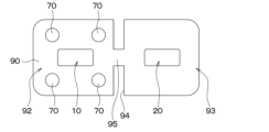
- the diagnostic sensor 1 of this embodiment is configured to have one wiring board 90, as shown in FIG. 12.
- the wiring board 90 is configured of a printed circuit board or the like, similar to the first wiring board 30 and the second wiring board 40 described above. That is, the wiring board 90 has one surface 90a and the other surface 90b, and the one-surface wiring on the one surface 90a side and the other-surface wiring on the other surface 90b side (not shown) are appropriately electrically connected via through-hole wiring or the like.
- the vibration sensor 10 and the sound sensor 20 are arranged on one surface 90a of the wiring board 90. That is, in this embodiment, the vibration sensor 10 and the sound sensor 20 are arranged on a common wiring board 90.
- the wiring board 90 is formed with a communication hole 91 that is connected to the communication hole 22a and the recess 210a of the sound sensor 20 and guides sound to the vibration area 222.
- the wiring board 90 is fixed to the housing 50 by inserting a fastening member 70 around the vibration sensor 10 and fastening the fastening member 70 to the facing portion 500 with the other surface 90b positioned on the facing portion 500 side.
- the wiring board 90 is also fixed to the housing 50 so that the communication hole 91 is connected to the through hole 510. Furthermore, the wiring board 90 is arranged so that the vibration sensor 10 is positioned on the opposite side to the connector portion 55 side relative to the sound sensor 20, and the magnet 540 overlaps with the vibration sensor 10 in the normal direction.
- the fastening member 70 is not inserted through the wiring board 90 around the sound sensor 20.
- vibrations of the housing 50 are more likely to be transmitted to the vibration sensor 10 via the fastening member 70, and are less likely to be transmitted to the sound sensor 20.
- a transmission member 101 is arranged between the part of the other surface 90b of the wiring board 90 facing the vibration sensor 10 and the inner surface 54.
- a blocking member 102 is arranged between the periphery of the communication hole 31 on the other surface 90b of the wiring board 90 and the inner surface 54.
- the transmission member 101 is preferably made of a material that makes it easy for the vibration of the housing 50 to be transmitted to the vibration sensor 10 via the wiring board 90.
- the transmission member 101 is preferably made of an epoxy resin or the like having a high elasticity.
- the blocking member 102 is intended to suppress the sound induced from the through hole 510 from leaking out from between the other surface 90b of the wiring board 90 and the inner surface 54, and is configured in the same manner as the blocking member 80 in the first embodiment.
- the transmission member 101 and the blocking member 102 in this embodiment are made of a material with a higher elasticity than the blocking member 102.
- the fastening member 70 and the transmission member 101 correspond to the fixed member. Furthermore, in this embodiment, the transmission member 101 is arranged so that it has a portion that overlaps with the magnet 540 in the normal direction. In other words, in this embodiment, the vibration sensor 10 and the transmission member 101 are arranged so that they overlap with the magnet 540 in the normal direction.
- the wiring board 90 of this embodiment has a first arrangement region 92 in which the vibration sensor 10 is arranged, and a second arrangement region 93 in which the sound sensor 20 is arranged.
- a slit 94 is formed between the first arrangement region 92 and the second arrangement region 93.
- the first arrangement region 92 and the second arrangement region 93 are connected via a beam portion 95.
- the fastening member 70 of this embodiment is arranged in the first arrangement region 92.
- FIG. 13 shows an example in which the slits 94 are formed from each of two opposing sides of the wiring board 90 in the normal direction, but the slits 94 may be formed from only one of the two opposing sides. Furthermore, the slits 94 may be formed so as to be scattered between the two opposing sides of the wiring board 90.
- the storage space 50a of the housing 50 is roughly divided into a first space S1 on the side where the vibration sensor 10 is arranged and a second space S2 on the side where the sound sensor 20 is arranged.
- the case 61 is formed with a protrusion 611 that abuts against the other surface 90b of the wiring board 90.
- the lid portion 62 is formed with a protrusion 612 that abuts against the one surface 90a of the wiring board 90.
- the first space S1 and the second space S2 are roughly divided by the protrusions 611, 612.
- the diagnostic sensor 1 is configured to have a vibration sensor 10 and a sound sensor 20, so that the same effects as in the first embodiment can be obtained.
- the vibration sensor 10 and the sound sensor 20 are arranged on a single wiring board 90, and this wiring board 90 is fixed to the housing 50. This reduces the number of parts and improves the ease of assembling the wiring board 90 to the housing 50.
- the vibration sensor 10 is disposed on the opposite side of the connector portion 55 from the sound sensor 20. This makes it possible to prevent vibrations from being transmitted to the vibration sensor 10 when the connector portion 55, which is connected to an external circuit portion or the like, is pulled by the circuit portion or the like.
- a slit 94 is formed in the wiring board 90 between the first arrangement region 92 in which the vibration sensor 10 is arranged and the second arrangement region 93 in which the sound sensor 20 is arranged. This makes it difficult for vibrations to propagate from the first arrangement region 92 side to the second arrangement region 93 side, and prevents vibrations from being included as noise in the sound detection signal. In other words, the detection accuracy of the sound sensor 20 can be improved.
- the storage space 50a is divided into a first space S1 and a second space S2. This prevents vibrations in the first space S1 from affecting the second space S2, and also prevents sounds in the second space S2 from affecting the first space S1. This improves the detection accuracy of the vibration sensor 10 and the sound sensor 20.
- the housing 50 is provided with the protrusions 611, 612 to separate the first space S1 and the second space S2.
- the first space S1 and the second space S2 may also be separated by, for example, arranging shielding plates or the like on the one surface 90a side and the other surface 90b side of the wiring board 90.
- the magnet 540 has a first magnet 541 and a second magnet 542.
- the first magnet 541 is arranged rotationally symmetrically with respect to the sealing member 530.
- the second magnet 542 is arranged closer to the connector section 55 than the first magnet 541.
- the first magnet 541 can be said to be arranged rotationally symmetrically with respect to the sealing member 530 in a predetermined range in which the first magnet 541 is arranged.
- the diagnostic sensor 1 is configured to have a vibration sensor 10 and a sound sensor 20, so that the same effects as in the first embodiment can be obtained.
- the magnet 540 has a first magnet 541 and a second magnet 542, and the second magnet 542 is arranged closer to the connector portion 55 than the first magnet 541.
- the connector portion 55 is a portion that is connected to an external circuit portion or the like, and is a portion that is likely to be subjected to vibration when the connector portion 55 is pulled by the circuit portion or the like. For this reason, by arranging the second magnet 542 on the connector portion 55 side as in this embodiment, it is possible to prevent the diagnostic sensor 1 from peeling off from the mounted member 300.
- a blocking member 102 is disposed between the periphery of the communication hole 91 on the other surface 90b of the wiring board 90 and the inner surface 54.
- an absorbent film 103 is disposed between the communication hole 91 and the portion of the other surface 90b of the wiring board 90 where the blocking member 102 is disposed. In other words, the absorbent film 103 is disposed closer to the communication hole 91 than the blocking member 102 in the normal direction.
- the absorbing film 103 absorbs foreign matter that may enter through the through hole 510 of the housing 50 and prevents the foreign matter from reaching the sound sensor 20, and is made of, for example, a porous film.
- the absorbing film 103 may be made of a hydrophilic film.
- the absorbing film 103 may be made of a new oil film. Note that such an absorbing film 103 is particularly effective when the sound detection element 200 is of an electrostatic type.
- the absorbing film 103 of this embodiment is a porous film, it may be arranged to block the through hole 510 or the communication hole 91. In this case, sound is applied to the sound sensor 20 through the holes of the porous film. And, if the absorbing film 103 is arranged to block the through hole 510 or the communication hole 91, it is possible to further prevent foreign matter from reaching the sound sensor 20.
- the diagnostic sensor 1 is configured to have a vibration sensor 10 and a sound sensor 20, so that the same effects as in the first embodiment can be obtained.
- an absorbing film 103 is disposed between the portion of the other surface 90b of the wiring board 90 where the blocking member 102 is disposed and the communication hole 91. This absorbs foreign matter that may enter through the through hole 510 of the housing 50, thereby preventing the foreign matter from reaching the sound sensor 20 and preventing a decrease in the detection accuracy of the sound sensor 20.
- the vibration sensor 10 is disposed on the other surface 90b side of the wiring board 90.
- the transmission member 101 is disposed between the vibration sensor 10 and one inner surface 54 of the housing 50, and is disposed so as to cover the periphery of the vibration sensor 10, such as the side surfaces. In other words, the vibration sensor 10 is covered by the transmission member 101 in a portion different from the portion facing the wiring board 90.
- the diagnostic sensor 1 is configured to have a vibration sensor 10 and a sound sensor 20, so that the same effects as in the first embodiment can be obtained.
- the vibration sensor 10 is covered with the transmission member 101 at a portion thereof different from the portion facing the wiring board 90. This makes it easier for the vibration of the housing 50 to be transmitted to the vibration sensor 10 via the transmission member 101, thereby improving the sensitivity of the vibration sensor 10.
- the vibration sensor 10 may be covered with a propagation member 101 as shown in Fig. 17. That is, in this diagnostic sensor 1, a through hole 96 is formed around the vibration sensor 10 in the wiring substrate 90. The propagation member 101 is disposed so as to cover the vibration sensor 10 through the through hole 96.
- a magnet base 550 with variable holding force is arranged on the outer surface 51 side as an attachment member.
- the holding force (i.e., the adhesive force) of the magnet base 550 changes when the permanent magnet rotates or displaces, changing the magnetic flux flowing through the yoke.
- the magnet base 550 is also provided with an operating unit 560 that rotates or displaces the permanent magnet.
- the permanent magnet is made of, for example, neodymium, ferrite, cobalt, etc., and the yoke is made of stainless steel, etc.
- the permanent magnet is made of, for example, a disk-shaped magnet or a rod-shaped magnet.
- the permanent magnet is made by stacking multiple disk-shaped magnets. When the permanent magnet is made by stacking multiple disk-shaped magnets, the permanent magnet is made by stacking multiple disk-shaped magnets so that the stacked parts have different magnetic poles.
- the operating unit 560 can rotate or displace the permanent magnet, it may be provided integrally with the magnet base 550, or may be formed separately from the magnet base 550.
- the diagnostic sensor 1 is configured to have a vibration sensor 10 and a sound sensor 20, so that the same effects as in the first embodiment can be obtained.
- the diagnostic sensor 1 is configured with a magnet base 550 whose mounting member has an adjustable holding force. This makes it easy to attach and detach the diagnostic sensor 1 to the mounted member 300, while increasing the holding force when the diagnostic sensor 1 is attached to the mounted member 300.
- the holding force of the magnet base 550 be adjusted to 50 N or less so that a person can easily attach and detach the diagnostic sensor 1 to the mounted member 300.
- the holding force of the magnet base 550 be adjusted to 50 N or more after the diagnostic sensor 1 is attached to the mounted member 300 so that misalignment can be suppressed.
- the sealing member 530 can be easily crushed when the diagnostic sensor 1 is attached to the mounted member 300. This sufficiently prevents foreign matter from entering the vicinity of the through hole 510 in the housing 50. For example, if the sealing member 530 is not crushed sufficiently, foreign matter such as an oil film may reach the vicinity of the through hole 510 in the housing 50. In this case, according to the inventors' studies, it has been confirmed that the detection accuracy of signals, particularly on the high frequency side, decreases. Therefore, by adjusting the holding force of the magnet base 550 to sufficiently crush the sealing member 530, it is possible to prevent the detection accuracy of signals on the high frequency side from decreasing.
- the diagnostic sensor 1 can be easily removed from the mounted member 300.
- the way in which it vibrates may change.
- foreign matter such as metal cutting chips is left attached to the housing 50, safety may be reduced. Therefore, by making it possible to easily remove the diagnostic sensor 1 from the mounted member 300, foreign matter such as metal cutting chips can be easily removed, and safety can be improved while preventing a decrease in vibration detection accuracy due to changes in vibration.
- the vibration sensor 10 and the sound sensor 20 are packaged, but the vibration sensor 10 and the sound sensor 20 do not have to be packaged. Furthermore, if the vibration sensor 10 and the sound sensor 20 are packaged, they may have a QFP (short for Quad Flat Package) structure with lead terminals.
- QFP short for Quad Flat Package
- the fastening member 70 is a screw member.
- the fastening member 70 may be a pin member, a joining member, or the like, or may be a combination of a screw member, a pin member, and a joining member.
- the magnet 540 has been described as an example of the mounting member.
- the mounting member may be configured for screw members or snap-fit connection as long as it can fix the diagnostic sensor 1 to the mounted member 300. If the mounting member is configured for screw members or snap-fit connection, a structure for attaching the mounting member to the mounted member 300 is appropriately formed.
- the magnet 540 as the mounting member and the sealing member 530 may be attached to the mounted member 300 side.
- the first detection frequency range and the second detection frequency range partially overlap.
- the first detection frequency range and the second detection frequency range do not necessarily have to have overlapping frequencies.
- the connector portion 55 may be located closer to the outer surface 52 than the center portion C2.
- the fastening member 70 does not have to be positioned so as to overlap the magnet 540 in the normal direction.
- the propagation member 101 does not have to be positioned so as to overlap the magnet 540 in the normal direction.
- the vibration sensor 10 may be positioned closer to the connector portion 55 than the sound sensor 20.
- the wiring board 90 does not need to have the slits 94 formed.
- the storage space 50a does not have to be divided into the first space S1 and the second space S2.
- the blocking member 80 does not have to be provided.
- the blocking member 102 does not have to be provided.
- control unit 2 is disposed outside the diagnostic sensor 1 and connected to the connector unit 55.
- control unit 2 may be incorporated into the first wiring board 30 or the second wiring board 40.
- control unit 2 may be incorporated into the wiring board 90.
- the vibration determination signal is compared with a vibration threshold value as a vibration determination element in the abnormality determination.
- the vibration determination element is not limited to the vibration threshold value, and may be, for example, the amount of change from a certain time before, or a waveform relating to the time and signal until the end of one or more processing operations.
- the detailed configuration of the vibration determination element is not particularly limited as long as it can determine an abnormality.
- a signal that can be compared with the vibration determination element is appropriately derived as the vibration determination signal.
- the sound determination signal and sound determination elements in the abnormality determination are not particularly limited and can be changed as appropriate. Also, in the self-diagnosis determination, the determination signals and diagnostic determination elements are not particularly limited and can be changed as appropriate.
- the third embodiment can be combined with the first embodiment, and the magnet 540 can be configured to have a first magnet 541 and a second magnet 542.
- the fourth embodiment can be combined with the first embodiment, and the magnet 540 can be configured to have an absorbing film 103.
- the configuration in which the storage space 50a in the second embodiment is divided into a first space S1 and a second space S2 can be combined with the first embodiment.
- the second wiring board 40 can be enlarged in the planar direction and the outer edge portion can be abutted against the housing 50, thereby dividing the space into a first space S1 on the side where the vibration sensor 10 is arranged and a second space S2 on the side where the sound sensor 20 is arranged.
- the sixth embodiment can be combined with each embodiment, and a magnet base 550 can be provided as an attachment member. Also, combinations of the above embodiments can be further combined.
- control unit and the method described in the present disclosure may be realized by a dedicated computer provided by configuring a processor and memory programmed to execute one or more functions embodied in a computer program.
- control unit and the method described in the present disclosure may be realized by a dedicated computer provided by configuring a processor with one or more dedicated hardware logic circuits.
- control unit and the method described in the present disclosure may be realized by one or more dedicated computers configured by combining a processor and memory programmed to execute one or more functions with a processor configured with one or more hardware logic circuits.
- the computer program may be stored in a computer-readable non-transient tangible recording medium as instructions executed by the computer.
- a diagnostic sensor that is attached to a mounted member (300) and used, a vibration sensor (10) that outputs a vibration detection signal corresponding to vibration in a first detection frequency range; a sound sensor (20) that outputs a sound detection signal corresponding to a sound propagating through a space in a second detection frequency range including a frequency higher than the first detection frequency range;
- a diagnostic sensor comprising: a housing (50) having an accommodation space (50a) for accommodating the vibration sensor and the sound sensor, and having a through hole (510) formed on one surface (51) facing the mounted member when attached to the mounted member, for guiding sound.
- the housing has a connector portion (55), A diagnostic sensor described in a third aspect, wherein the mounting member has a first mounting member (541) arranged rotationally symmetrically with respect to the sealing member, and a second mounting member (542) arranged on the connector portion side of the first mounting member.
- the housing has another surface (52) opposite to the one surface, and has a connector portion (55) on a side surface (53) connected to the one surface and the other surface, A diagnostic sensor described in any one of the first to fourth aspects, wherein the connector portion is provided on the one surface side of the housing rather than a center portion (C2) between the one surface and the other surface.
- the diagnostic sensor according to any one of the first to fifth aspects, wherein the first wiring board and the second wiring board are stacked and fixed to the housing via a fixing member (70) in a state in which the first wiring board is located on the one side and the sound induced from the through hole is propagated through the space and applied to a detection section (222) that outputs the sound detection signal of the sound sensor.
- the wiring board has a first arrangement area (92) in which the vibration sensor is arranged and a second arrangement area (93) in which the sound sensor is arranged, and at least the first arrangement area is fixed to the housing via a fixing member (70, 101) in a state in which sound induced from the through hole propagates through the space and is applied to a detection section (222) that outputs the sound detection signal of the sound sensor.
- the housing has a connector portion (55), The diagnostic sensor according to a seventh aspect, wherein the vibration sensor is located on an opposite side to the connector portion side with respect to the sound sensor.
- the mounting member (540, 550) is disposed on one surface of the housing and fixes the housing to the mounted member,
- the diagnostic sensor according to any one of the sixth to ninth aspects, wherein the fixing member is disposed at a position overlapping the mounting member in a normal direction to the one surface.
- a diagnostic sensor according to any one of the first to eleventh aspects, wherein a blocking member (80, 102) is arranged between a wiring board on which the sound sensor is arranged and a portion surrounding the through hole in the housing.
- a diagnostic sensor described in a twelfth aspect in which an absorbing film (103) is arranged between a wiring board on which the sound sensor is arranged and the surrounding portion of the through hole in the housing, together with the blocking member, at a position closer to the through hole than the blocking member in the normal direction to the one surface.
- a diagnostic sensor according to any one of the sixth to ninth aspects, in which a closed space through which sound from the mounted component propagates when attached to the mounted component is defined as an acoustic space (V3), and when it is known that a desired frequency of the sound when attached to the mounted component is included in the second detection frequency range, the volume of the acoustic space is adjusted so that the resonant frequency of the acoustic space matches the desired frequency.
- V3 a closed space through which sound from the mounted component propagates when attached to the mounted component
- a diagnostic sensor as described in any one of the sixth to ninth aspects in which a closed space through which sound from the mounted component propagates when attached to the mounted component is defined as an acoustic space (V3), and when it is known that the desired frequency of the sound when attached to the mounted component is different from the second detection frequency range, or when it is unknown whether the desired frequency of the sound when attached to the mounted component is included in the second detection frequency range, the volume of the acoustic space is adjusted so that the resonant frequency of the acoustic space is outside the second detection frequency range.
- V3 a closed space through which sound from the mounted component propagates when attached to the mounted component
- the diagnostic sensor according to a seventh aspect, wherein the vibration sensor has a portion different from a portion facing the wiring board covered by a transmission member (101) serving as the fixing member provided in the housing.
- a mounting member (550) is disposed on one surface of the housing and fixes the housing to the mounted member,
- the diagnostic sensor according to any one of claims 1 to 18, wherein the mounting member includes a magnet base capable of changing a holding force.
- a state determination system comprising: A diagnostic sensor according to any one of the first to nineteenth aspects, provided on the mounted member (300) having a determination target portion (360); A control unit (2) for performing a predetermined process, The control unit is a state determination system that determines the state of the determination target part by using a vibration determination signal based on the vibration detection signal and a sound determination signal based on the sound detection signal.
- the first detection frequency range and the second detection frequency range include an overlapping frequency range that overlaps with each other
- the control unit performs self-diagnosis to determine whether or not an abnormality has occurred in at least one of the vibration sensor and the sound sensor by comparing a differential determination signal based on the difference between the vibration detection signal and the sound detection signal with a diagnostic determination element in the superimposed frequency range.
- the first detection frequency range and the second detection frequency range include an overlapping frequency range that overlaps with each other,
- a state determination system according to any one of the 20th to 22nd aspects, wherein the control unit, when determining that the vibration detection signal is greater than a noise judgment value in the superimposed frequency range, performs a filter setting process to set a filter that attenuates sound detection signals in a frequency range greater than the noise judgment value, and when deriving the sound determination signal in the state determination, derives the sound determination signal using the filter.
- a state determination system according to any one of the 20th to 23rd aspects, wherein, when performing the state determination, the control unit divides a detection frequency range in which the detection signal is output into a plurality of ranges, compares the detection signal with the determination element in each divided frequency range, and changes the determination element for each divided frequency range depending on its reliability.
Landscapes
- Physics & Mathematics (AREA)
- General Physics & Mathematics (AREA)
- Measurement Of Mechanical Vibrations Or Ultrasonic Waves (AREA)
Abstract
Description
本開示は、配置制約を低減できる診断センサおよびこれを用いた状態判定システムを提供することを目的とする。
第1実施形態の状態判定システムについて、図面を参照しつつ説明する。本実施形態の状態判定システムは、判定対象部の状態を検出するのに用いられ、例えば、切削、研削加工に用いられる刃具における摩耗等の状態判定、およびプレス機や成型機の割れ、欠け、かじり等の状態判定等に用いられる。また、本実施形態の状態判定システムは、例えば、ベアリングの損傷、摩耗、潤滑状態等の状態判定、およびファンや配管の空気漏れや異音等の状態判定等に用いられる。さらに、本実施形態の状態判定システムは、例えば、被削材を加工する際の最適な加工条件を抽出するための状態判定に用いられる。なお、被削材を加工する際の最適な加工条件を抽出するとは、判定対象部を被削材とし、被削材の状態から最適な加工条件を抽出することである。以下では、例として、刃具を有する工作機械に状態判定システムを適用し、刃具の状態判定を行う例について説明する。但し、上記のように、本実施形態の状態判定システムは、種々の判定対象部の状態判定を行うのに利用され得る。
上記第1実施形態の変形例について説明する。例えば、上記第1実施形態では、ステップS103にて振動判定信号と振動閾値とを比較する際、振動閾値は、各周波数範囲で異なっていてもよいし、同じとされていてもよい例について説明した。しかしながら、例えば、振動センサ10は高周波側ほど検出精度が不安定になるため、振動閾値は、高周波側ほど高くなるようにしてもよい。また、例えば、制御部2は、振動閾値を超える振動判定信号の周波数を複数回に渡って記憶するようにし、当該記憶に基づいて振動閾値を可変させる自己学習を行うようにしてもよい。つまり、振動閾値を異ならせる場合には、信頼性の高い周波数ほど振動閾値が低くなるように、信頼性に応じて周波数範囲の閾値を変更するようにしてもよい。同様に、音閾値は、周波数範囲で異なっていてもよく、異ならせる場合には、信頼性の高い周波数ほど音閾値が低くなるようにしてもよい。これによれば、さらに判定精度を高くできる。
第2実施形態について説明する。本実施形態は、第1実施形態に対し、配線基板を1つにしたものである。その他に関しては、第1実施形態と同様であるため、ここでは説明を省略する。
第3実施形態について説明する。本実施形態は、第2実施形態に対し、磁石を追加したものである。その他に関しては、第2実施形態と同様であるため、ここでは説明を省略する。
第4実施形態について説明する。本実施形態は、第2実施形態に対し、吸収膜を追加したものである。その他に関しては、第2実施形態と同様であるため、ここでは説明を省略する。
第5実施形態について説明する。本実施形態は、第2実施形態に対し、伝搬部材101の配置方法を変更したものである。その他に関しては、第2実施形態と同様であるため、ここでは説明を省略する。
上記第5実施形態の変形例について説明する。上記第5実施形態において、図17に示されるように振動センサ10を伝搬部材101で被覆するようにしてもよい。すなわち、この診断センサ1では、配線基板90における振動センサ10の周囲に貫通孔96が形成されている。そして、伝搬部材101は、貫通孔96を通じて振動センサ10を被覆するように配置されている。
第6実施形態について説明する。本実施形態は、第1実施形態に対し、取付部材の構成を変更したものである。その他に関しては、第1実施形態と同様であるため、ここでは説明を省略する。
本開示は、実施形態に準拠して記述されたが、本開示は当該実施形態や構造に限定されるものではないと理解される。本開示は、様々な変形例や均等範囲内の変形をも包含する。加えて、様々な組み合わせや形態、さらには、それらに一要素のみ、それ以上、あるいはそれ以下、を含む他の組み合わせや形態をも、本開示の範疇や思想範囲に入るものである。
上記した本開示については、例えば以下に示す観点として把握することができる。
被実装部材(300)に取り付けられて用いられる診断センサであって、
第1検出周波数範囲の振動に応じた振動検出信号を出力する振動センサ(10)と、
前記第1検出周波数範囲より高い周波数を含む第2検出周波数範囲における空間を伝搬する音に応じた音検出信号を出力する音センサ(20)と、
前記振動センサおよび前記音センサを収容する収容空間(50a)を有し、前記被実装部材に取り付けられる際に前記被実装部材と対向する一面(51)側に音を誘導する貫通孔(510)が形成された筐体(50)と、を備える診断センサ。
前記筐体の一面に配置され、前記筐体を前記被実装部材に固定する取付部材(540、550)と、
前記筐体の一面のうちの前記貫通孔の周囲に備えられ、前記被実装部材に取り付けられる際に押し潰されて前記筐体と前記被実装部材との間の空間を封止する封止部材(530)と、を備える第1の観点に記載の診断センサ。
前記取付部材は、前記筐体の一面側に、前記封止部材を基準として回転対称に配置される部分を有する第2の観点に記載の診断センサ。
前記筐体は、コネクタ部(55)を有し、
前記取付部材は、前記封止部材を基準として回転対称に配置される第1取付部材(541)と、前記第1取付部材より前記コネクタ部側に配置される第2取付部材(542)とを有する第3の観点に記載の診断センサ。
前記筐体は、前記一面と反対側の他面(52)を有すると共に、前記一面および前記他面と繋がる側面(53)にコネクタ部(55)を有し、
前記コネクタ部は、前記筐体の側面のうちの、前記一面と前記他面との間の中心部(C2)よりも前記一面側に備えられている第1ないし第4の観点のいずれか1つに記載の診断センサ。
前記音センサが配置される第1配線基板(30)と、
前記振動センサが配置される第2配線基板(40)と、を有し、
前記第1配線基板および前記第2配線基板は、積層されつつ、前記第1配線基板が前記一面側に位置する状態であり、前記音センサの前記音検出信号を出力する検出部(222)に前記貫通孔から誘導された音が前記空間を伝搬して印加される状態で、固定部材(70)を介して前記筐体に固定されている第1ないし第5の観点のいずれか1つに記載の診断センサ。
前記振動センサおよび前記音センサが配置され、前記筐体の収容空間に配置される配線基板(90)を有し、
前記配線基板は、前記振動センサが配置される第1配置領域(92)と、前記音センサが配置される第2配置領域(93)と、を有し、前記音センサの前記音検出信号を出力する検出部(222)に前記貫通孔から誘導された音が前記空間を伝搬して印加される状態で、少なくとも前記第1配置領域が固定部材(70、101)を介して前記筐体に固定されている第1ないし第5の観点のいずれか1つに記載の診断センサ。
前記筐体は、コネクタ部(55)を有し、
前記振動センサは、前記音センサより前記コネクタ部側と反対側に位置している第7の観点に記載の診断センサ。
前記配線基板は、前記第1配置領域と前記第2配置領域との間にスリット(94)が形成されている第7または第8の観点に記載の診断センサ。
前記筐体の一面に配置され、前記筐体を前記被実装部材に固定する取付部材(540、550)を有し、
前記固定部材は、前記一面に対する法線方向において、前記取付部材と重なる位置に配置されている第6ないし第9の観点のいずれか1つに記載の診断センサ。
前記収容空間は、前記振動センサが配置される第1空間(S1)と、前記音センサが配置される第2空間(S2)とに区画されている第1ないし第10の観点のいずれか1つに記載の診断センサ。
前記音センサが配置される配線基板と前記筐体における貫通孔の周囲の部分との間には、閉塞部材(80、102)が配置されている第1ないし第11の観点のいずれか1つに記載の診断センサ。
前記音センサが配置される配線基板と前記筐体における貫通孔の周囲の部分との間には、前記閉塞部材と共に、前記一面に対する法線方向において前記閉塞部材よりも前記貫通孔側となる位置に吸収膜(103)が配置されている第12の観点に記載の診断センサ。
前記振動センサが配置される配線基板は、前記被実装部材に取り付けられた際の振動における所望の周波数が前記第1検出周波数範囲に含まれることが既知である場合、前記配線基板の共振周波数が前記所望の周波数と一致する状態で前記筐体に固定される第6ないし第9の観点のいずれか1つに記載の診断センサ。
前記振動センサが配置される配線基板は、前記被実装部材に取り付けられた際の振動における所望の周波数が前記第1検出周波数範囲と異なることが既知である場合、または前記被実装部材に取り付けられた際の振動における所望の周波数が前記第1検出周波数範囲に含まれるか不明である場合、前記配線基板の共振周波数が前記第1検出周波数範囲外となる状態で前記筐体に固定される第6ないし第9の観点のいずれか1つに記載の診断センサ。
前記被実装部材に取り付けられた際に前記被実装部材からの音が伝搬する閉空間を音響空間(V3)とすると、前記音響空間は、前記被実装部材に取り付けられた際の音における所望の周波数が前記第2検出周波数範囲に含まれることが既知である場合、前記音響空間の共鳴周波数が前記所望の周波数と一致するように体積が調整される第6ないし第9の観点のいずれか1つに記載の診断センサ。
前記被実装部材に取り付けられた際に前記被実装部材からの音が伝搬する閉空間を音響空間(V3)とすると、前記音響空間は、前記被実装部材に取り付けられた際の音における所望の周波数が前記第2検出周波数範囲と異なることが既知である場合、または前記被実装部材に取り付けられた際の音における所望の周波数が前記第2検出周波数範囲に含まれるか不明である場合、前記音響空間の共鳴周波数が前記第2検出周波数範囲外となるように体積が調整される第6ないし第9の観点のいずれか1つに記載の診断センサ。
前記振動センサは、前記筐体に備えられた前記固定部材としての伝搬部材(101)により、前記配線基板と対向する部分と異なる部分が覆われている第7の観点に記載の診断センサ。
前記筐体の一面に配置され、前記筐体を前記被実装部材に固定する取付部材(550)を有し、
前記取付部材は、保持力を変化させることができるマグネットベースを含んで構成されている第1ないし第18のいずれか1つに記載の診断センサ。
状態判定システムであって、
判定対象部(360)を有する前記被実装部材(300)に備えられた第1ないし第19の観点のいずれか1つに記載の診断センサと、
所定の処理を行う制御部(2)と、備え、
前記制御部は、前記振動検出信号に基づく振動判定信号と前記音検出信号に基づく音判定信号とを用いて前記判定対象部の状態判定を行う状態判定システム。
前記制御部は、前記振動判定信号と振動判定要素とを比較することと、前記音判定信号と音判定要素とを比較することの少なくとも一方を行って前記状態判定を行う第20の観点に記載の状態判定システム。
前記第1検出周波数範囲および前記第2検出周波数範囲は、重畳する重畳周波数範囲を含んでおり、
前記制御部は、前記重畳周波数範囲において、前記振動検出信号と前記音検出信号との差に基づく差分判定信号と診断判定要素とを比較して前記振動センサおよび前記音センサの少なくとも一方に異常が発生しているか否かを判定する自己診断を行う第20または第21の観点に記載の状態判定システム。
前記第1検出周波数範囲および前記第2検出周波数範囲は、重畳する重畳周波数範囲を含んでおり、
前記制御部は、前記重畳周波数範囲において、前記振動検出信号がノイズ判定値より大きいと判定すると、前記ノイズ判定値より大きくなる周波数範囲の音検出信号を減衰させるフィルタを設定するフィルタ設定処理を行い、前記状態判定にて前記音判定信号を導出する際、前記フィルタを用いて前記音判定信号を導出する第20ないし第22の観点のいずれか1つに記載の状態判定システム。
前記制御部は、前記状態判定を行う際、前記検出信号が出力される検出周波数範囲を複数に分割し、分割したそれぞれの周波数範囲において前記検出信号と前記判定要素とを比較することを行い、分割したそれぞれの周波数範囲の前記判定要素を信頼性に応じて変更する第20ないし第23の観点のいずれか1つに記載の状態判定システム。
Claims (24)
- 被実装部材(300)に取り付けられて用いられる診断センサであって、
第1検出周波数範囲の振動に応じた振動検出信号を出力する振動センサ(10)と、
前記第1検出周波数範囲より高い周波数を含む第2検出周波数範囲における空間を伝搬する音に応じた音検出信号を出力する音センサ(20)と、
前記振動センサおよび前記音センサを収容する収容空間(50a)を有し、前記被実装部材に取り付けられる際に前記被実装部材と対向する一面(51)側に音を誘導する貫通孔(510)が形成された筐体(50)と、を備える診断センサ。 - 前記筐体の一面に配置され、前記筐体を前記被実装部材に固定する取付部材(540、550)と、
前記筐体の一面のうちの前記貫通孔の周囲に備えられ、前記被実装部材に取り付けられる際に押し潰されて前記筐体と前記被実装部材との間の空間を封止する封止部材(530)と、を備える請求項1に記載の診断センサ。 - 前記取付部材は、前記筐体の一面側に、前記封止部材を基準として回転対称に配置される部分を有する請求項2の記載の診断センサ。
- 前記筐体は、コネクタ部(55)を有し、
前記取付部材は、前記封止部材を基準として回転対称に配置される第1取付部材(541)と、前記第1取付部材より前記コネクタ部側に配置される第2取付部材(542)とを有する請求項3に記載の診断センサ。 - 前記筐体は、前記一面と反対側の他面(52)を有すると共に、前記一面および前記他面と繋がる側面(53)にコネクタ部(55)を有し、
前記コネクタ部は、前記筐体の側面のうちの、前記一面と前記他面との間の中心部(C2)よりも前記一面側に備えられている請求項1に記載の診断センサ。 - 前記音センサが配置される第1配線基板(30)と、
前記振動センサが配置される第2配線基板(40)と、を有し、
前記第1配線基板および前記第2配線基板は、積層されつつ、前記第1配線基板が前記一面側に位置する状態であり、前記音センサの前記音検出信号を出力する検出部(222)に前記貫通孔から誘導された音が前記空間を伝搬して印加される状態で、固定部材(70)を介して前記筐体に固定されている請求項1に記載の診断センサ。 - 前記振動センサおよび前記音センサが配置され、前記筐体の収容空間に配置される配線基板(90)を有し、
前記配線基板は、前記振動センサが配置される第1配置領域(92)と、前記音センサが配置される第2配置領域(93)と、を有し、前記音センサの前記音検出信号を出力する検出部(222)に前記貫通孔から誘導された音が前記空間を伝搬して印加される状態で、前記第1配置領域が固定部材(70、101)を介して前記筐体に固定されている請求項1に記載の診断センサ。 - 前記筐体は、コネクタ部(55)を有し、
前記振動センサは、前記音センサより前記コネクタ部側と反対側に位置している請求項7に記載の診断センサ。 - 前記配線基板は、前記第1配置領域と前記第2配置領域との間にスリット(94)が形成されている請求項7に記載の診断センサ。
- 前記筐体の一面に配置され、前記筐体を前記被実装部材に固定する取付部材(540、550)を有し、
前記固定部材は、前記一面に対する法線方向において、前記取付部材と重なる位置に配置されている請求項6ないし9のいずれか1つに記載の診断センサ。 - 前記収容空間は、前記振動センサが配置される第1空間(S1)と、前記音センサが配置される第2空間(S2)とに区画されている請求項6ないし9のいずれか1つに記載の診断センサ。
- 前記音センサが配置される配線基板と前記筐体における貫通孔の周囲の部分との間には、閉塞部材(80、102)が配置されている請求項6ないし9のいずれか1つに記載の診断センサ。
- 前記音センサが配置される配線基板と前記筐体における貫通孔の周囲の部分との間には、前記閉塞部材と共に、前記一面に対する法線方向において前記閉塞部材よりも前記貫通孔側となる位置に吸収膜(103)が配置されている請求項12に記載の診断センサ。
- 前記振動センサが配置される配線基板は、前記被実装部材に取り付けられた際の振動における所望の周波数が前記第1検出周波数範囲に含まれることが既知である場合、前記配線基板の共振周波数が前記所望の周波数と一致する状態で前記筐体に固定される請求項6ないし9のいずれか1つに記載の診断センサ。
- 前記振動センサが配置される配線基板は、前記被実装部材に取り付けられた際の振動における所望の周波数が前記第1検出周波数範囲と異なることが既知である場合、または前記被実装部材に取り付けられた際の振動における所望の周波数が前記第1検出周波数範囲に含まれるか不明である場合、前記配線基板の共振周波数が前記第1検出周波数範囲外となる状態で前記筐体に固定される請求項6ないし9のいずれか1つに記載の診断センサ。
- 前記被実装部材に取り付けられた際に前記被実装部材からの音が伝搬する閉空間を音響空間(V3)とすると、前記音響空間は、前記被実装部材に取り付けられた際の音における所望の周波数が前記第2検出周波数範囲に含まれることが既知である場合、前記音響空間の共鳴周波数が前記所望の周波数と一致するように体積が調整される請求項6ないし9のいずれか1つに記載の診断センサ。
- 前記被実装部材に取り付けられた際に前記被実装部材からの音が伝搬する閉空間を音響空間(V3)とすると、前記音響空間は、前記被実装部材に取り付けられた際の音における所望の周波数が前記第2検出周波数範囲と異なることが既知である場合、または前記被実装部材に取り付けられた際の音における所望の周波数が前記第2検出周波数範囲に含まれるか不明である場合、前記音響空間の共鳴周波数が前記第2検出周波数範囲外となるように体積が調整される請求項6ないし9のいずれか1つに記載の診断センサ。
- 前記振動センサは、前記筐体に備えられた前記固定部材としての伝搬部材(101)により、前記配線基板と対向する部分と異なる部分が覆われている請求項7に記載の診断センサ。
- 前記筐体の一面に配置され、前記筐体を前記被実装部材に固定する取付部材(550)を有し、
前記取付部材は、保持力を変化させることができるマグネットベースを含んで構成されている請求項1に記載の診断センサ。 - 状態判定システムであって、
判定対象部(360)を有する前記被実装部材(300)に備えられた請求項1に記載の診断センサと、
所定の処理を行う制御部(2)と、備え、
前記制御部は、前記振動検出信号に基づく振動判定信号と前記音検出信号に基づく音判定信号とを用いて前記判定対象部の状態判定を行う状態判定システム。 - 前記制御部は、前記振動判定信号と振動判定要素とを比較することと、前記音判定信号と音判定要素とを比較することの少なくとも一方を行って前記状態判定を行う請求項20に記載の状態判定システム。
- 前記第1検出周波数範囲および前記第2検出周波数範囲は、重畳する重畳周波数範囲を含んでおり、
前記制御部は、前記重畳周波数範囲において、前記振動検出信号と前記音検出信号との差に基づく差分判定信号と診断判定要素とを比較して前記振動センサおよび前記音センサの少なくとも一方に異常が発生しているか否かを判定する自己診断を行う請求項20に記載の状態判定システム。 - 前記第1検出周波数範囲および前記第2検出周波数範囲は、重畳する重畳周波数範囲を含んでおり、
前記制御部は、前記重畳周波数範囲において、前記振動検出信号がノイズ判定値より大きいと判定すると、前記ノイズ判定値より大きくなる周波数範囲の音検出信号を減衰させるフィルタを設定するフィルタ設定処理を行い、前記状態判定にて前記音判定信号を導出する際、前記フィルタを用いて前記音判定信号を導出する請求項20に記載の状態判定システム。 - 前記制御部は、前記状態判定を行う際、前記検出信号が出力される検出周波数範囲を複数に分割し、分割したそれぞれの周波数範囲において前記検出信号と前記判定要素とを比較することを行い、分割したそれぞれの周波数範囲の前記判定要素を信頼性に応じて変更する請求項20に記載の状態判定システム。
Priority Applications (4)
| Application Number | Priority Date | Filing Date | Title |
|---|---|---|---|
| EP24819112.4A EP4722668A1 (en) | 2023-06-05 | 2024-05-15 | Diagnostic sensor, and state determining system employing same |
| JP2025526024A JPWO2024252875A1 (ja) | 2023-06-05 | 2024-05-15 | |
| CN202480035671.3A CN121263664A (zh) | 2023-06-05 | 2024-05-15 | 诊断传感器以及使用了该诊断传感器的状态判定系统 |
| US19/407,512 US20260085967A1 (en) | 2023-06-05 | 2025-12-03 | Diagnostic sensor, and state determining system employing same |
Applications Claiming Priority (2)
| Application Number | Priority Date | Filing Date | Title |
|---|---|---|---|
| JP2023092601 | 2023-06-05 | ||
| JP2023-092601 | 2023-06-05 |
Related Child Applications (1)
| Application Number | Title | Priority Date | Filing Date |
|---|---|---|---|
| US19/407,512 Continuation US20260085967A1 (en) | 2023-06-05 | 2025-12-03 | Diagnostic sensor, and state determining system employing same |
Publications (1)
| Publication Number | Publication Date |
|---|---|
| WO2024252875A1 true WO2024252875A1 (ja) | 2024-12-12 |
Family
ID=93795390
Family Applications (1)
| Application Number | Title | Priority Date | Filing Date |
|---|---|---|---|
| PCT/JP2024/017986 Ceased WO2024252875A1 (ja) | 2023-06-05 | 2024-05-15 | 診断センサおよびこれを用いた状態判定システム |
Country Status (5)
| Country | Link |
|---|---|
| US (1) | US20260085967A1 (ja) |
| EP (1) | EP4722668A1 (ja) |
| JP (1) | JPWO2024252875A1 (ja) |
| CN (1) | CN121263664A (ja) |
| WO (1) | WO2024252875A1 (ja) |
Citations (6)
| Publication number | Priority date | Publication date | Assignee | Title |
|---|---|---|---|---|
| JPH03269221A (ja) * | 1990-03-19 | 1991-11-29 | Hitachi Ltd | 回転機器の異常音診断装置 |
| JPH05142033A (ja) * | 1991-11-19 | 1993-06-08 | Toshiba Corp | プラント機器の監視装置 |
| JPH06241882A (ja) * | 1993-02-18 | 1994-09-02 | Nippon Telegr & Teleph Corp <Ntt> | 音検知器 |
| JPH07174613A (ja) * | 1993-12-21 | 1995-07-14 | Tokyo Gas Co Ltd | 超音波センサユニット |
| JP2000193519A (ja) | 1998-12-25 | 2000-07-14 | Fuji Ceramics:Kk | 振動・アコ―スティックエミッション複合センサ |
| WO2020162426A1 (ja) * | 2019-02-05 | 2020-08-13 | 日本電気株式会社 | 解析装置、解析方法、およびプログラム、ならびに、センサの構造 |
-
2024
- 2024-05-15 EP EP24819112.4A patent/EP4722668A1/en active Pending
- 2024-05-15 JP JP2025526024A patent/JPWO2024252875A1/ja active Pending
- 2024-05-15 CN CN202480035671.3A patent/CN121263664A/zh active Pending
- 2024-05-15 WO PCT/JP2024/017986 patent/WO2024252875A1/ja not_active Ceased
-
2025
- 2025-12-03 US US19/407,512 patent/US20260085967A1/en active Pending
Patent Citations (6)
| Publication number | Priority date | Publication date | Assignee | Title |
|---|---|---|---|---|
| JPH03269221A (ja) * | 1990-03-19 | 1991-11-29 | Hitachi Ltd | 回転機器の異常音診断装置 |
| JPH05142033A (ja) * | 1991-11-19 | 1993-06-08 | Toshiba Corp | プラント機器の監視装置 |
| JPH06241882A (ja) * | 1993-02-18 | 1994-09-02 | Nippon Telegr & Teleph Corp <Ntt> | 音検知器 |
| JPH07174613A (ja) * | 1993-12-21 | 1995-07-14 | Tokyo Gas Co Ltd | 超音波センサユニット |
| JP2000193519A (ja) | 1998-12-25 | 2000-07-14 | Fuji Ceramics:Kk | 振動・アコ―スティックエミッション複合センサ |
| WO2020162426A1 (ja) * | 2019-02-05 | 2020-08-13 | 日本電気株式会社 | 解析装置、解析方法、およびプログラム、ならびに、センサの構造 |
Also Published As
| Publication number | Publication date |
|---|---|
| JPWO2024252875A1 (ja) | 2024-12-12 |
| US20260085967A1 (en) | 2026-03-26 |
| EP4722668A1 (en) | 2026-04-08 |
| CN121263664A (zh) | 2026-01-02 |
Similar Documents
| Publication | Publication Date | Title |
|---|---|---|
| CN102812729B (zh) | 声音传感器与麦克风 | |
| CN105744453B (zh) | 具有绝缘的导电板的电容式麦克风 | |
| KR101368697B1 (ko) | 초음파 진동장치 | |
| US10017376B2 (en) | MEMS element including a stress decoupling structure and a component including such a MEMS element | |
| CN108444587A (zh) | 声传感器 | |
| WO2013129386A1 (ja) | センサ装置 | |
| US20070237345A1 (en) | Method for reducing phase variation of signals generated by electret condenser microphones | |
| US10555087B2 (en) | Acoustic sensor and capacitive transducer | |
| US10408619B2 (en) | Composite sensor | |
| US10508919B2 (en) | Composite sensor | |
| WO2024252875A1 (ja) | 診断センサおよびこれを用いた状態判定システム | |
| CN110418950B (zh) | 压力传感器 | |
| KR101218550B1 (ko) | 초음파 센서 | |
| CN100380128C (zh) | 加速度传感器单元 | |
| EP4473276B1 (en) | Compact vibration sensor | |
| JP2007060285A (ja) | シリコンマイクロホンパッケージ | |
| CN218330239U (zh) | 一种新型测振仪传感器及测量仪器 | |
| EP4621366A1 (en) | Equipment state monitoring system | |
| JP7137987B2 (ja) | マイクロホン装置 | |
| US20230046600A1 (en) | Acceleration detection device | |
| JPH06273224A (ja) | 振動検知センサ | |
| KR102880488B1 (ko) | 마이크로폰용 액티브 커플러 | |
| US20250369794A1 (en) | Vibration detection device | |
| JP6549467B2 (ja) | 保護ケース、振動センサおよびその製造方法、ならびに脈拍測定装置 | |
| JPH0659049A (ja) | 粉体検知装置 |
Legal Events
| Date | Code | Title | Description |
|---|---|---|---|
| 121 | Ep: the epo has been informed by wipo that ep was designated in this application |
Ref document number: 24819112 Country of ref document: EP Kind code of ref document: A1 |
|
| ENP | Entry into the national phase |
Ref document number: 2025526024 Country of ref document: JP Kind code of ref document: A |
|
| WWE | Wipo information: entry into national phase |
Ref document number: 2025526024 Country of ref document: JP |
|
| WWE | Wipo information: entry into national phase |
Ref document number: CN2024800356713 Country of ref document: CN |
|
| ENP | Entry into the national phase |
Ref document number: 2024819112 Country of ref document: EP Effective date: 20260105 |
|
| WWE | Wipo information: entry into national phase |
Ref document number: 2024819112 Country of ref document: EP |
|
| NENP | Non-entry into the national phase |
Ref country code: DE |
|
| ENP | Entry into the national phase |
Ref document number: 2024819112 Country of ref document: EP Effective date: 20260105 |
|
| ENP | Entry into the national phase |
Ref document number: 2024819112 Country of ref document: EP Effective date: 20260105 |
|
| ENP | Entry into the national phase |
Ref document number: 2024819112 Country of ref document: EP Effective date: 20260105 |
|
| ENP | Entry into the national phase |
Ref document number: 2024819112 Country of ref document: EP Effective date: 20260105 |
|
| ENP | Entry into the national phase |
Ref document number: 2024819112 Country of ref document: EP Effective date: 20260105 |
|
| WWP | Wipo information: published in national office |
Ref document number: 2024819112 Country of ref document: EP |