WO2024252833A1 - 膨張弁 - Google Patents
膨張弁 Download PDFInfo
- Publication number
- WO2024252833A1 WO2024252833A1 PCT/JP2024/017069 JP2024017069W WO2024252833A1 WO 2024252833 A1 WO2024252833 A1 WO 2024252833A1 JP 2024017069 W JP2024017069 W JP 2024017069W WO 2024252833 A1 WO2024252833 A1 WO 2024252833A1
- Authority
- WO
- WIPO (PCT)
- Prior art keywords
- valve
- chamber
- flow path
- hole
- valve body
- Prior art date
- Legal status (The legal status is an assumption and is not a legal conclusion. Google has not performed a legal analysis and makes no representation as to the accuracy of the status listed.)
- Ceased
Links
Images




Classifications
-
- F—MECHANICAL ENGINEERING; LIGHTING; HEATING; WEAPONS; BLASTING
- F25—REFRIGERATION OR COOLING; COMBINED HEATING AND REFRIGERATION SYSTEMS; HEAT PUMP SYSTEMS; MANUFACTURE OR STORAGE OF ICE; LIQUEFACTION SOLIDIFICATION OF GASES
- F25B—REFRIGERATION MACHINES, PLANTS OR SYSTEMS; COMBINED HEATING AND REFRIGERATION SYSTEMS; HEAT PUMP SYSTEMS
- F25B41/00—Fluid-circulation arrangements
- F25B41/30—Expansion means; Dispositions thereof
- F25B41/31—Expansion valves
- F25B41/325—Expansion valves having two or more valve members
-
- F—MECHANICAL ENGINEERING; LIGHTING; HEATING; WEAPONS; BLASTING
- F16—ENGINEERING ELEMENTS AND UNITS; GENERAL MEASURES FOR PRODUCING AND MAINTAINING EFFECTIVE FUNCTIONING OF MACHINES OR INSTALLATIONS; THERMAL INSULATION IN GENERAL
- F16K—VALVES; TAPS; COCKS; ACTUATING-FLOATS; DEVICES FOR VENTING OR AERATING
- F16K31/00—Actuating devices; Operating means; Releasing devices
- F16K31/001—Actuating devices; Operating means; Releasing devices actuated by volume variations caused by an element soluble in a fluid or swelling in contact with a fluid
-
- F—MECHANICAL ENGINEERING; LIGHTING; HEATING; WEAPONS; BLASTING
- F25—REFRIGERATION OR COOLING; COMBINED HEATING AND REFRIGERATION SYSTEMS; HEAT PUMP SYSTEMS; MANUFACTURE OR STORAGE OF ICE; LIQUEFACTION SOLIDIFICATION OF GASES
- F25B—REFRIGERATION MACHINES, PLANTS OR SYSTEMS; COMBINED HEATING AND REFRIGERATION SYSTEMS; HEAT PUMP SYSTEMS
- F25B41/00—Fluid-circulation arrangements
- F25B41/30—Expansion means; Dispositions thereof
- F25B41/31—Expansion valves
- F25B41/33—Expansion valves with the valve member being actuated by the fluid pressure, e.g. by the pressure of the refrigerant
- F25B41/335—Expansion valves with the valve member being actuated by the fluid pressure, e.g. by the pressure of the refrigerant via diaphragms
-
- F—MECHANICAL ENGINEERING; LIGHTING; HEATING; WEAPONS; BLASTING
- F25—REFRIGERATION OR COOLING; COMBINED HEATING AND REFRIGERATION SYSTEMS; HEAT PUMP SYSTEMS; MANUFACTURE OR STORAGE OF ICE; LIQUEFACTION SOLIDIFICATION OF GASES
- F25B—REFRIGERATION MACHINES, PLANTS OR SYSTEMS; COMBINED HEATING AND REFRIGERATION SYSTEMS; HEAT PUMP SYSTEMS
- F25B41/00—Fluid-circulation arrangements
- F25B41/30—Expansion means; Dispositions thereof
- F25B41/31—Expansion valves
- F25B41/34—Expansion valves with the valve member being actuated by electric means, e.g. by piezoelectric actuators
- F25B41/345—Expansion valves with the valve member being actuated by electric means, e.g. by piezoelectric actuators by solenoids
-
- F—MECHANICAL ENGINEERING; LIGHTING; HEATING; WEAPONS; BLASTING
- F25—REFRIGERATION OR COOLING; COMBINED HEATING AND REFRIGERATION SYSTEMS; HEAT PUMP SYSTEMS; MANUFACTURE OR STORAGE OF ICE; LIQUEFACTION SOLIDIFICATION OF GASES
- F25B—REFRIGERATION MACHINES, PLANTS OR SYSTEMS; COMBINED HEATING AND REFRIGERATION SYSTEMS; HEAT PUMP SYSTEMS
- F25B2341/00—Details of ejectors not being used as compression device; Details of flow restrictors or expansion valves
- F25B2341/06—Details of flow restrictors or expansion valves
- F25B2341/068—Expansion valves combined with a sensor
- F25B2341/0683—Expansion valves combined with a sensor the sensor is disposed in the suction line and influenced by the temperature or the pressure of the suction gas
Definitions
- the present invention relates to an expansion valve.
- expansion valve is known to be an expansion valve equipped with a solenoid valve.
- an expansion valve is applied to a refrigeration cycle having multiple evaporators connected in parallel, and has a function to control the degree of superheat of the refrigerant on the outlet side of the evaporator as well as a function to shut off the circuit in the refrigeration cycle.
- Patent Document 1 discloses an expansion valve that has a valve port provided in a communication passage that connects a primary passage through which high-pressure refrigerant flows and a valve chamber, and is equipped with a solenoid valve that opens and closes the valve port.
- the expansion valve can be operated by opening the valve port with the solenoid valve, and the expansion valve can be forcibly closed by blocking the valve port.
- the present invention was made in consideration of the above problems, and aims to provide an expansion valve that can maintain a closed state at will by utilizing the fluid pressure of the refrigeration cycle.
- the solenoid valve of the present invention comprises: a valve body having a valve chamber and a valve seat; a power element provided in the valve body and having a displaceable displacement portion; a valve body disposed in the valve chamber; a first biasing device that biases the valve body toward the valve seat; an actuating rod that is provided in the valve body, disposed between the displacement portion and the valve body, and that drives the valve body in response to displacement of the displacement portion; a syringe member provided in the valve body, movably housing a portion of the actuation rod therein, and defining a cylinder chamber between the syringe member and the displacement portion that is expandable and contractable in the movement direction of the valve body; a movement restriction portion that restricts movement of the syringe member toward the valve chamber; a supply unit that supplies the fluid in the valve chamber or the fluid upstream of the valve chamber to the cylinder chamber. It is characterized by:
- the present invention provides an expansion valve that can maintain a closed state at will by utilizing the fluid pressure of the refrigeration cycle.
- FIG. 6 of an expansion valve according to a first modified example is a vertical cross-sectional view similar to FIG. 6 of an expansion valve according to a second modified example.
- FIG. 9 is a vertical cross-sectional view similar to FIG. 6 of an expansion valve according to a third modified example.
- FIG. 10 is a vertical cross-sectional view similar to FIG. 6 of an expansion valve according to a fourth modified example.
- FIG. 11 is a vertical cross-sectional view similar to FIG. 6 of an expansion valve according to a fifth modified example.
- FIG. 12 is a vertical cross-sectional view similar to FIG. 6 of an expansion valve according to a sixth modified example.
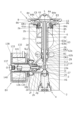
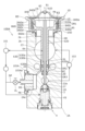
- FIG. Fig. 1 is a schematic cross-sectional view of an expansion valve 1 in an open state in this embodiment, and shows a refrigeration cycle 100 to which this is connected.
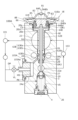
- Fig. 2 is a longitudinal cross-sectional view of the expansion valve 1 in a cross section shifted in phase by 90 degrees around the axis L from Fig. 1, showing the open state.
- Fig. 3 is a cross-sectional view showing an enlarged view of the periphery of the solenoid valve EV shown in Fig. 2.
- Fig. 4 is a longitudinal cross-sectional view of the expansion valve 1 in a cross section similar to Fig. 2, showing the closed state.
- upstream of the valve chamber refers to the side closer to the condenser than the valve chamber
- downstream of the valve chamber refers to the side closer to the evaporator than the valve chamber.
- the expansion valve 1 comprises a valve body 2 with a valve chamber VS, a valve element 3, a biasing device (also called a first biasing device) 4, an actuating rod 5, a syringe member 6, and a power element 8.
- the axis of the expansion valve 1 is designated as L.
- the power element 8 side is the upper side
- the biasing device 4 side is the lower side.
- the valve body 2 includes a first flow path 21, a second flow path 22, and a return flow path (low pressure flow path) 23 in addition to the valve chamber VS.
- the first flow path 21 is a supply side flow path, and a refrigerant (also called a fluid) is supplied to the valve chamber VS via the supply side flow path.
- the second flow path 22 is a discharge side flow path, and the fluid in the valve chamber VS is discharged outside the expansion valve via the working rod insertion hole 27, the intermediate passage 22a, and the discharge side flow path.
- the first flow path 21 and the valve chamber VS are connected via the small diameter passage 21a.
- the actuating rod 5 is inserted with a gap into the actuating rod insertion hole 27 of the valve body 2, and is guided by the central hole 28 and held so that it can be displaced in the direction of the axis L.
- the lower end of the actuating rod 5 contacts the upper surface of the valve body 3, and the upper end of the actuating rod 5 abuts against the lower surface of the stopper member 84 of the power element 8.
- the syringe member 6 arranged around the actuating rod 5 is provided on the valve body 2, movably houses a part of the actuating rod 5 inside, and forms a cylinder chamber between the stopper member 84 that can expand and contract in the direction of movement of the valve body 3.
- the syringe member 6 is composed of a disk base (also simply called the base) 61 on the upper end side and a shaft portion (also called the syringe member shaft portion) 62 on the lower end side that are coaxially connected, and has a through hole 63 that penetrates from the upper end side to the lower end.
- the through hole 63 has a first hole 63a on the upper end side and a second hole 63b on the lower end side.
- the second hole 63b has an inner diameter smaller than the first hole 63a, and slidably fits onto the outer periphery of the actuating rod 5.
- the disk base 61 is housed in a cylindrical recess 84a of a stopper member 84 of the power element 8, which will be described later.
- a first circumferential groove 61a is formed on the outer periphery of the disk base 61, and a first O-ring OR1 is disposed inside the first circumferential groove 61a, which provides a seal between the cylindrical recess 84a and the disk base 61.
- a second circumferential groove 62a is formed on the outer periphery of the shaft portion 62 near the lower end, and a second O-ring OR2 is placed inside the second circumferential groove 62a to seal between the expanded diameter hole (first hole) 26 of the valve body 2 and the shaft portion 62.
- the shaft portion 62 fits slidably into the expanded diameter hole 26.
- a thin-diameter portion 62b is formed on the outer periphery of the lower end of the shaft portion 62 below the second circumferential groove 62a, and the outer diameter of the thin-diameter portion 62b is smaller than the outer diameter of the shaft portion 62 other than the thin-diameter portion 62b.
- a connection hole 62d is formed in the thin-diameter portion 62b, penetrating between its inner and outer peripheries. Since the enlarged diameter hole 26 has a substantially uniform inner diameter, there is a gap between the outer periphery of the reduced diameter portion 64 and the inner periphery of the enlarged diameter hole 26.
- a medium diameter hole 29 is formed, which is smaller in diameter than the enlarged diameter hole 26 and larger in diameter than the central hole 28.
- a third O-ring OR3 through which the actuating rod 5 passes, is disposed within the medium diameter hole 29, providing a seal between the actuating rod 5 and the medium diameter hole 29.
- the space between the enlarged diameter hole 26 and the medium diameter hole 29, which are sealed by the second O-ring OR2 and the third O-ring OR3, is the pressure equalizing chamber (also called the pressure equalizing space) EC.
- a communication hole 2d is formed in the valve body 2, extending downward from the enlarged diameter hole 26 facing the pressure equalizing chamber EC at an angle to the axis L (see Figure 2).
- the syringe member 6 extends along the axis L from the power element 8 through the communication passage 2b, the return flow passage 23, and the enlarged diameter hole 26 formed in the valve body 2 to the step 26a between the enlarged diameter hole 26 and the medium diameter hole 29.
- the power element 8 is attached to an opening 2a provided at the top of the valve body 2.
- the opening 2a is connected via a communication passage 2b to a return flow passage 23 through which the refrigerant from the evaporator passes.
- the power element 8 has a plug 81, an upper cover member 82, a diaphragm 83, a stopper member 84 that constitutes the displacement portion, and a receiving member 86.
- a hole 82a is formed at the top of the upper cover member 82, which can be sealed with a plug 81.
- the diaphragm 83 is made of, for example, a thin plate material with multiple concentric circular projections and recesses.
- the stopper member 84 which is a generally cylindrical member with a top, has a disk portion 84b and a circular tube portion 84c that is coaxially connected to the underside of the disk portion 84b, and the inside of the circular tube portion 84c forms a cylindrical recess 84a.
- An annular locking member (also called a locking portion) 85 is attached to the inner circumferential step at the lower end of the circular tube portion 84c.
- the locking member 85 is attached to the circular tube portion 84c by crimping the crimping portion 84d at the lower end of the circular tube portion 84c, which is disposed on the outer periphery of the locking member 85, radially inward, thereby preventing the disk base portion 61 from coming off the stopper member 84.
- the locking member 85 abuts against the syringe member 6, thereby preventing the syringe member 6 from moving beyond a predetermined position toward the valve chamber relative to the stopper member 84. In other words, the locking member 85 prevents the syringe member 6 from slipping out of the stopper member 84.
- the portion of the stopper member 84 that abuts against the syringe member 6 is formed separately as the locking member 85
- the portion of the stopper member 84 that abuts against the syringe member 6 may be formed integrally with the stopper member 84.
- the disk base 61 is capable of being displaced in the axial direction between an upper position where its upper end abuts the lower surface of the disk portion 84b (contact position where it abuts against the stopper member 84: Figure 2), and a lower position where its lower end abuts against the upper surface of the locking member 85.
- the shaft portion 62 abuts against the step portion (also called the bottom surface of the hole) 26a between the enlarged diameter hole 26 and the medium diameter hole 29 before the disk base 61 abuts against the locking member 85.
- the step portion of the medium diameter hole 29 functions as a movement restricting portion that restricts the movement of the syringe member 6 towards the valve chamber VS.
- the axial dimension of the syringe member 6 is set so that the lower end of the shaft portion 62 abuts against the step portion 26a between the enlarged diameter hole 26 and the medium diameter hole 29 (the abutting position where it abuts against the valve body 2: Figure 4), and the disk base 61 is spaced from the underside of the disk portion 84b of the stopper member 84.
- the space between the disk portion 84b and the disk base 61 is the cylinder chamber CS.
- the cylinder chamber CS is connected only to the through hole 63.
- An annular recess 84e is formed on the underside of the disk portion 84b, facing the outer periphery of the upper end of the disk base 61, and the inside of the annular recess 84e forms part of the cylinder chamber CS.
- the receiving member 86 has a flange portion with an outer diameter approximately the same as the outer diameter of the top cover member 82, and a hollow cylindrical portion connected to the lower end of the flange portion, and a male thread 86c is formed on the outer periphery of the hollow cylindrical portion.
- the outer peripheries of the flange portion of the upper cover member 82, the diaphragm 83, and the receiving member 86 are overlapped with the stopper member 84 inside, and the outer peripheries are circumferentially welded together by, for example, TIG welding, laser welding, plasma welding, or the like to form a housing.
- the syringe member 6 may be assembled inside the stopper member 84 in advance, or the syringe member 6 may be assembled after welding.
- the working gas is injected into the space surrounded by the top cover member 82 and the diaphragm 83 (called the pressure actuated chamber PA) through the hole 82a formed in the top cover member 82, and the hole 82a is then sealed with a plug 81, which is then fixed to the top cover member 82 using projection welding or the like.
- the diaphragm 83 is pressurized by the working gas sealed in the pressure actuated chamber PA in such a way that it bulges towards the receiving member 86, and is supported by abutting against the upper surface of the stopper member 84, which is located in the lower space (valve chamber side chamber) LS surrounded by the diaphragm 83 and the receiving member 86.
- the stopper member 84 since the disk portion 84b of the stopper member 84 is held by the receiving member 86, the stopper member 84 will not come out of the power element 8.
- the syringe member 6 together with the stopper member 84 is inserted into the valve body 2 from its lower end side, and the second hole 63b is fitted onto the actuating rod 5. Furthermore, the male threads 86c of the receiving member 86 are screwed into the female threads of the opening 2a of the valve body 2, and the power element 8 is fixed to the valve body 2 by screwing it in. The gap between the valve body 2 and the power element 8 is sealed by a packing PK. In this state, the lower space LS of the power element 8 is connected to the return flow path 23, i.e., they have the same internal pressure.
- the biasing device 4 has a coil spring 41 made of circular wire wound in a spiral shape, a valve body support 42 attached to the upper end of the coil spring 41 and supporting the valve body 3, a spring receiving member 43 attached to the valve body 2 while supporting the lower end of the coil spring 41, and a vibration-proof member 44 sandwiched between the valve body support 42 and the coil spring 41.
- the spring receiving member 43 seals the valve chamber VS of the valve body 2, and has the function of supporting the end of the coil spring 41 that biases the valve body 3 toward the valve seat 20.
- the spherical valve body 3 is welded to the upper surface of the valve body support 42, and the two are integrated.
- the vibration-proof member 44 has, for example, a radially protruding claw portion that elastically engages with the inner circumference of the valve chamber VS, and has the function of suppressing vibration of the valve body 3. Note that the vibration-proof member 44 is described in detail in, for example, JP 2018-025331 A, so a detailed description will be omitted.
- the solenoid valve EV is a first valve device and a second valve device, or a drive unit, that can switch between a state in which the inflow path is open and the outflow path is closed, and a state in which the outflow path is open and the inflow path is closed.
- the inflow path and the solenoid valve EV constitute a supply unit and a discharge unit.
- the axis of the solenoid valve EV is O.
- the axis O is perpendicular to the axis L.
- the valve body 2 is formed with a circular large opening 2e that opens outward along the axis O, a medium opening 2f with a smaller diameter than the large opening 2e, and a small opening 2g with a smaller diameter than the medium opening 2f.
- the bottom of the large opening 2e is connected to the valve chamber VS via an inlet hole 2h.
- a communication hole 2d opens on the inner circumference at the middle position of the medium opening 2f.
- the bottom of the small opening 2g is connected to the intermediate passage 22a via an outlet hole (also called a connection passage) 2j.
- the inlet hole 2h, the high pressure chamber HS, the middle opening 2f, the communication hole 2d, the enlarged diameter hole 26, the connection hole 62d, and the through hole 63 form an inflow path
- the connection hole 62d and the through hole 63 form a second hole
- the inlet hole 2h forms a first flow path portion
- the communication hole 2d forms a second flow path portion.
- the through hole 63, the connection hole 62d, the enlarged diameter hole 26, the communication hole 2d, the medium opening 2f, the small opening 2g, and the outlet hole 2j form an outflow path.
- the small opening 2g and the outlet hole 2j form a branch flow path, the outlet hole 2j forms a third flow path section, and the high pressure chamber HS, the medium opening 2f, and the small opening 2g form a connection chamber.
- the intermediate passage 22a forms the downstream flow path downstream of the valve seat 20.
- a cylindrical valve seat member 112 is disposed within the middle opening 2f, and is fixed to the middle opening 2f by crimping a cylindrical crimped portion 2i formed at the bottom of the large opening (also called a recess) 2e radially inward.
- the valve seat member 112 is disposed between the opening of the first flow path portion and the opening of the third flow path portion in the connection chamber to prevent the flow of refrigerant from the first flow path portion to the third flow path portion, cover the opening of the second flow path portion, and form a gap between the opening of the third flow path portion.
- the valve seat member 112 has a through hole (also called a through hole) 112a extending along the axis O, a circumferential groove 112b formed around the entire circumference at a middle position in the direction of the axis O, a radial hole 112c that radially connects the through hole 112a and the circumferential groove 112b, and a recess 112d formed at the end on the small opening 2g side.
- the circumferential groove 112b is connected to the communication hole 2d.
- the circumferential groove 112b and the radial hole 112c form a relay path.
- a part of the high pressure chamber HS, the through hole 112a, the radial hole 112c, and the circumferential groove 112b of the valve seat member 112 form a first communication flow path, and the through hole 112a, the radial hole 112c, the circumferential groove 112b, and the small opening 2g of the valve seat member 112 form a second communication flow path.
- a first annular seal member SL1 is attached by adhesive or the like within the recess 112d of the valve seat member 112, and a second annular seal member SL2 is attached by adhesive or the like to the end opposite the recess 112d.
- the inner diameters of the first seal member SL1 and the second seal member SL2 are approximately equal to the inner diameter of the through hole 112a.
- the first seal member SL1 abuts against the step at the boundary between the middle opening 2f and the small opening 2g, and the second seal member SL2 abuts against the inner circumference of the middle opening 2f, thereby sealing between the valve seat member 112 and the valve body 2.
- the cylindrical valve shaft member 113 has a long shaft portion (also simply called the shaft portion) 113a inserted so as to penetrate the through hole 112a of the valve seat member 112 and the first and second seal members SL1 and SL2, a flange portion (also called the flange portion) 113b having a larger diameter than the through hole 112a, and a short shaft portion 113c. There are gaps between the outer periphery of the long shaft portion 113a and the inner periphery of the through hole 112a, the first and second seal members SL1 and SL2 through which the refrigerant can pass, and the valve shaft member 113 is movable relative to the valve seat member 112 in the direction of the axis O.
- valve shaft member 113 is movable between a second position in which the first flow path portion and the second flow path portion are connected to each other via the first communication flow path of the connection chamber, and both the first flow path portion and the second flow path portion are not connected to the third flow path portion, and a first position in which the second flow path portion and the third flow path portion are connected to each other via the second communication flow path of the connection chamber, and both the second flow path portion and the third flow path portion are not connected to the first flow path portion.
- a compression spring (also called a second biasing device) 114 is disposed around the short shaft portion 113c between the bottom of the small opening 2g and the opposing surface of the flange portion 113b, biasing the valve shaft member 113 toward the large opening 2e with respect to the bottom of the small opening 2g.
- the solenoid valve EV and the compression spring 114 constitute a drive device.
- the solenoid valve EV comprises an annular base 120, a coil 132 for energizing, a yoke 133, a pipe 141 arranged on the inner circumference of the yoke 133 and extending in the direction of the axis O, a plunger (displacement member) 135 arranged on the inner circumference of the pipe 141 so as to be able to slide freely in the direction of the axis O, an attractor 140 fixedly arranged on the inner circumference of the end of the pipe 141, and a housing 138 arranged to cover these.
- the end of the pipe 141 is fixed to the inner circumference of the base 120 by press-fitting or brazing, and the base 120 is fixed to the valve body 2 by screwing the male thread 121 formed on the outer circumference of the base 120 into the female thread 2k formed on the inner circumference of the large opening 2e of the valve body 2.
- An O-ring OR4 is placed between the bottom of the large opening 2e and the base 120, sealing the gap between the base 120 and the valve body 2.
- the high-pressure chamber HS is connected to the inlet hole 2h and can also be connected to the through hole 112a of the valve seat member 112.
- a female threaded portion 142 is formed on the end face of the suction element 140 opposite the pipe 141.
- the suction element 140 and the housing 138 are joined by screwing the mounting bolt 137 into the female threaded portion 142 with the housing 138 interposed therebetween.
- the housing 138 is fixed to the base 120 via a spacer 139.
- the cylindrical plunger 135 is made of a magnetic material and is formed by connecting an enlarged diameter cylindrical portion 135a to a reduced diameter cylindrical portion 135b whose diameter is larger than the inner diameter of the through hole 112a.
- a circular recess 135c is formed at the end of the reduced diameter cylindrical portion 135b, into which the end of the long shaft portion 113a of the valve shaft member 113 exposed from the valve seat member 112 is loosely fitted (i.e., relatively displaceable in the direction of the axis O).
- the plunger 135 is biased toward the valve seat member 112 by a compression coil spring 136 compressed between the plunger 135 and the attractor 140.
- the tip surface of the plunger 135 is formed into a surface that abuts against the valve shaft member 113 to disconnect the opening of the through hole 112a and the connecting chamber.
- the plunger 135 of the solenoid valve EV is in a first position (described later).
- the pressure of the refrigerant in the cylinder chamber CS becomes approximately equal to the pressure in the intermediate passage 22a (and the return passage 23), as described later.
- This allows the stopper member 84 to approach the syringe member 6, and therefore the operating rod 5 is driven in accordance with the deformation of the diaphragm 83, allowing the expansion valve 1 to perform its normal opening operation.
- the expansion valve 1 is supplied with high-pressure refrigerant from the condenser 102. More specifically, the high-pressure refrigerant from the condenser 102 is supplied to the first flow path 21.
- valve disc 3 When the valve disc 3 is seated on the valve seat 20, the first flow path 21 upstream of the valve chamber VS and the second flow path 22 downstream of the valve chamber VS are not in communication. On the other hand, when the valve disc 3 is separated from the valve seat 20, the refrigerant supplied to the valve chamber VS is sent to the evaporator through the actuating rod insertion hole 27 and the second flow path 22.
- the expansion valve 1 is switched between the closed state (see Figure 4) and the open state ( Figure 2) by the actuating rod 5 connected to the power element 8.
- the power element 8 is provided with a pressure actuated chamber PA and a lower space LS separated by a diaphragm 83. Therefore, when the working gas in the pressure actuated chamber PA is liquefied, the actuating rod 5 moves toward the diaphragm due to the biasing force of the biasing device 4, and when the liquefied working gas is vaporized, the driving force (valve opening force) of the power element 8 is transmitted via the stopper member 84, and the actuating rod 5 moves toward the valve body. In this way, the expansion valve 1 is switched between the open and closed states depending on the pressure difference between the pressure actuated chamber PA and the lower space LS.
- the lower space LS of the power element 8 is connected to the return flow path 23. Therefore, the phase (gas phase, liquid phase, etc.) of the working gas in the pressure actuated chamber PA changes depending on the temperature and pressure of the refrigerant flowing through the return flow path 23, and the actuating rod 5 is driven.
- the amount of refrigerant supplied from the expansion valve 1 to the evaporator is automatically adjusted depending on the temperature and pressure of the refrigerant returning from the evaporator to the expansion valve 1.
- the plunger 135 When power is supplied to the coil 132 from an external power supply device, as shown in FIG. 4, the plunger 135 is urged and moves in a direction away from the valve seat member 112 against the urging force of the compression coil spring 136. As a result, the end of the plunger 135 moves away from the second seal member SL2, and the urging force of the compression spring 114 causes the flange portion 113b of the valve shaft member 113 to abut against the first seal member SL1, and the plunger 135 of the solenoid valve EV is in the second position.
- the pressure of the refrigerant in the high pressure chamber HS is transmitted from the through hole 112a of the valve seat member 112 to the cylinder chamber CS via the radial hole 112c, the circumferential groove 112b, the communication hole 2d, the pressure equalizing chamber EC, the connection hole 62d, the gap between the actuating rod 5 and the second hole 63b, and the through hole 63.
- the side opposite the cylinder chamber CS across the disk base 61 of the syringe member 6 faces the return flow path (low pressure space) 23 through which low pressure refrigerant passes.
- the cylinder chamber CS becomes high pressure
- the cylinder chamber CS tries to expand due to the pressure difference with the pressure of the refrigerant in the return flow path 23.
- the lower end of the shaft 62 of the syringe member 6 is maintained in contact with the step 26a between the enlarged diameter hole 26 and the medium diameter hole 29, so that the stopper member 84 is pushed relatively upward as the cylinder chamber CS becomes high pressure.
- the end of the plunger 135 abuts against the second seal member SL2, preventing the refrigerant in the high-pressure chamber HS from passing through the through hole 112a and leaking into the intermediate passage 22a, without affecting the operation of the refrigeration cycle 100.
- the internal pressure of the cylinder chamber CS is higher than the pressure of the refrigerant in the intermediate passage 22a. Therefore, in the first position, the pressure in the intermediate passage 22a is transmitted to the cylinder chamber CS through the outlet hole 2j, the small opening 2g, the through hole 112a, the radial hole 112c, the circumferential groove 112b, the communication hole 2d, the pressure equalizing chamber EC, the connection hole 62d, the gap between the actuating rod 5 and the second hole 63b, and the through hole 63, and the pressure of the refrigerant in the cylinder chamber CS quickly drops to approximately equal the pressure in the intermediate passage 22a (and the return flow path 23). As a result, the force pushing up the stopper member 84 disappears, and the pressing force from the diaphragm 83 can be transmitted to the upper end of the actuating rod 5, and the forced valve-closed state is released
- the plunger 135 is in contact with the second seal SL2
- the refrigerant is prevented from leaking from the high pressure chamber HS through the through hole 112a to the small opening 2g side, and the internal pressure of the pressure equalizing chamber EC and the cylinder chamber CS remains low. This allows the expansion valve 1 to perform its normal opening operation.
- the high-pressure refrigerant supplied from the condenser 102 can be introduced into the cylinder chamber CS to push up the stopper member 84, thereby realizing the forced valve closing function of the expansion valve 1 regardless of the pressure in the pressure actuated chamber PA.
- the refrigerant from the condenser 102 is introduced directly into the valve chamber VS without passing through the solenoid valve EV, thereby suppressing pressure loss, etc.
- the cylinder chamber CS is connected to the intermediate passage 22a, and the internal pressure of the cylinder chamber CS can be quickly reduced. This quickly eliminates the upward pressure from the cylinder chamber CS to the stopper member 84, and resumes the transmission of the pressure from the diaphragm 83 to the actuating rod 5 via the stopper member 84, allowing the expansion valve 1 to perform its normal opening operation.
- the pressure of the high-pressure refrigerant supplied from the condenser 102 varies depending on the conditions, so if high-pressure refrigerant is used to perform normal valve opening and closing operations, there is a risk that the normal valve opening and closing operations may become unstable.
- high-pressure refrigerant to perform forced valve closing operations, there is an advantage in that normal valve opening and closing operations can be performed stably.
- the syringe member 6 is supported on the valve body 2 via a second O-ring OR2 made of natural or synthetic resin, and the actuation rod 5 is supported via a third O-ring OR3 made of natural or synthetic resin. Therefore, even if vibration occurs in the syringe member 6 or the actuation rod 5, the vibration can be suppressed by the damping function of the second O-ring OR2 and the third O-ring OR3.
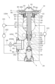
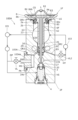
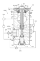
- Second Embodiment Figure 5 is a schematic cross-sectional view showing the open state of expansion valve 1A in the second embodiment
- Figure 6 is a longitudinal cross-sectional view showing the closed state of expansion valve 1A in the second embodiment, each of which diagrammatically shows a refrigeration cycle 100A to which expansion valve 1A is connected.
- a branch pipe is added to the refrigeration cycle 100A and an on-off valve is provided. Therefore, in addition to the branch pipe, the configuration of the valve body 2A is different from the above-mentioned embodiment, and the syringe member 6A has a hole 6e as a discharge portion. Since the other configurations are the same as those of the first embodiment, the same symbols are used for the common configurations and duplicate explanations are omitted.
- a branch pipe DP (connected to an external flow passage upstream of the valve chamber, and an inflow path through which the refrigerant upstream of the valve chamber flows into the cylinder chamber) is arranged, branching off from the pipe heading from the condenser 102 toward the valve chamber VS of the expansion valve 1A and heading toward the pipe base 105A of the expansion valve 1A, and an on-off valve (valve device) VL is attached to the branch pipe DP.
- the on-off valve VL can be selectively operated between an open position that opens the branch pipe DP and a closed position that closes it.
- the on-off valve VL and the inflow path form a supply section and a discharge section.
- the rest of the configuration is the same as that of the refrigeration cycle of the first embodiment.
- the communication hole 2d connects the pressure equalizing chamber EC of the valve body 2A to the outer periphery of the end of the large opening 2Ae.
- a pipe base 105A is attached to the large opening 2Ae.
- the pipe base 105A is fixed to the valve body 2A by screwing a male thread formed on the outer periphery of the pipe base 105A into a female thread formed on the inner periphery of the large opening 2Ae of the valve body 2A.
- a packing PK is placed between the large opening 2Ae and the pipe base 105A to seal the gap between the pipe base 105A and the valve body 2A. This forms a high-pressure chamber HS between the pipe base 105A and the large opening 2Ae.
- the piping base 105A has a piping section 105Aa that is connected to the branch piping DP via an on-off valve VL.
- the high pressure chamber HS is connected to the branch piping DP via the internal flow path of the piping base 105A and the piping section 105Aa, and is also connected to the pressure equalizing chamber EC via the communication hole 2d, but is not connected to the valve chamber VS.
- the rest of the configuration is the same as the expansion valve of the first embodiment.
- the syringe member 6A has a hole 6e that releases the pressure in the cylinder chamber CS downstream of the valve chamber VS.
- the hole 6e is formed, for example, in the shaft portion 62 of the syringe member 6A.
- the hole 6e connects the through hole 63 to the return flow path 23.
- the hole 6e enables the valve body 3 to be driven by the actuating rod 5 by exhausting pressure in the cylinder chamber CS, and is set to a size that allows the forced valve closure to be performed smoothly by maintaining sufficient pressure in the cylinder chamber CS when forced valve closure is performed.
- the on-off valve VL When the on-off valve VL is in the second position (open position), the high-pressure refrigerant in the branch pipe DP is supplied to the high-pressure chamber HS via the pipe section 105Aa, and the pressure of the refrigerant in the high-pressure chamber HS is transmitted to the cylinder chamber CS via the communication hole 2d, the pressure equalizing chamber EC, the connection hole 62d, and the through hole 63, making the internal pressure of the cylinder chamber CS high pressure.
- the on-off valve VL by operating the on-off valve VL to the second position, the high-pressure refrigerant supplied from the compressor 101 is introduced into the cylinder chamber CS, thereby interrupting the transmission of driving force from the diaphragm 83 to the actuating rod 5, thereby ensuring the forced closing operation of the expansion valve 1.
- a three-way valve can be provided in the pipe from the condenser 102, and the high-pressure refrigerant from the condenser 102 can be selectively sent out via the branch pipe DP to either the flow path leading to the high-pressure chamber HS or the flow path leading to the valve chamber VS.
- the flow path to the high pressure chamber HS and the flow path to the valve chamber VS are switched via a three-way switching valve.
- a three-way switching valve may be provided instead of the on-off valve VL arranged in the branch pipe DP to selectively switch between the flow path connecting the condenser 102 and the high pressure chamber HS and the flow path connecting the high pressure chamber HS and the inlet side of the evaporator 103.
- the flow path connecting the high pressure chamber HS and the inlet side of the evaporator 103 may be, for example, a flow path connecting the high pressure chamber HS and the second flow path 22, or a flow path connecting the high pressure chamber HS and the intermediate passage 22a.
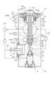
- FIG. 7 is a vertical cross-sectional view similar to FIG. 6 of an expansion valve 1B according to a first modified example, and shows a state in which the expansion valve 1B is installed in a refrigeration cycle 100A shown in schematic form.
- the expansion valve 1B of this embodiment only the shapes of the valve body 2B and the syringe member 6B differ from those of the second embodiment, and the other configurations are the same as those of the second embodiment, so the same symbols are used for the common configurations and duplicate explanations are omitted.
- the valve body 2B has an equalizing hole 29B that forms a pressure equalizing chamber EC, instead of a medium diameter hole that accommodates an O-ring, and is formed between the enlarged diameter hole 26 and the central hole 28 so as to connect to the communication hole 2d.
- a clearance is formed between the central hole 28 and the actuating rod 5. Even when high pressure is supplied to forcibly close the valve, high-pressure fluid flows out through the clearance, as described below, but this clearance is an amount that can maintain the pressure in the cylinder chamber CS at a pressure that can forcibly close the valve.
- the rest of the configuration of the valve body 2B is the same as in the second embodiment, so repeated explanations will be omitted.
- the syringe member 6B has a different shape for the shaft portion 62B, but the disk base 61 is the same as in the second embodiment.
- the shaft portion 62B has only a through hole 63B with a uniform inner diameter, and does not have a circumferential groove on the outer periphery for accommodating an O-ring, or a hole connecting the inside and outside.
- the lower end of the shaft portion 62B abuts against the step portion 26a between the enlarged diameter hole 26 and the pressure equalizing hole 29B.
- the rest of the configuration of the syringe member 6B is the same as in the above-mentioned embodiment.
- the on-off valve VL when the on-off valve VL is in the first position (closed position), the high pressure of the refrigerant in the branch pipe DP is no longer transmitted to the high pressure chamber HS, and some of the refrigerant in the cylinder chamber CS flows into the intermediate passage 22a through the through hole 63B, the gap between the central hole 28, and the actuating rod 5.
- This modified version eliminates the need for an O-ring, improving assembly and reducing costs.
- FIG. 8 is a vertical cross-sectional view similar to FIG. 6 of an expansion valve 1C according to a second modified example, and shows a state in which the expansion valve 1C is installed in a refrigeration cycle 100A shown in schematic form.
- the expansion valve 1C of this modified example only the shapes of the valve body 2C and the syringe member 6C differ from those of the second embodiment, and the other configurations are the same as those of the second embodiment, so the same symbols are used for the common configurations and duplicate explanations are omitted.
- the valve body 2C has a smaller inner diameter of the communication passage 2Cb than the inner diameter of the opening 2Ca (a hole in which the syringe member 6C is movably positioned), and therefore a step 2Cm (the bottom surface of the internal space of the opening 2Ca) is formed between the opening 2Ca and the communication passage 2Cb.
- the configuration of the valve body 2C is the same as in the second embodiment, so a duplicated description will be omitted.
- the syringe member 6C is formed by coaxially connecting a disk base (also simply called a base) 61C at the upper end side and a shaft portion (also called a syringe member shaft portion) 62C at the lower end side, and has a through hole 63C that penetrates from the upper end side to the lower end.
- the through hole 63C has a first hole 63Ca at the upper end side and a second hole 63Cb at the lower end side.
- the disk base 61C has a shape in which the lower part has a smaller diameter than the upper part, and this small diameter part is called an intermediate part 64C.
- the intermediate part 64c and the step part 2Cm that are the other end of the shaft part 62C, or the disk base 61C and the surface of the valve body 2C that faces the disk base 61C, constitute the movement restriction part.
- the second hole 63Cb has an inner diameter smaller than that of the first hole 63Ca, and is slidably fitted to the outer periphery of the actuation rod 5.
- a clearance is formed between the second hole 63Cb and the actuation rod 5. The clearance is set to an amount that allows high-pressure fluid to flow from the pressure equalizing chamber EC to the cylinder chamber CS through it.
- the disk base 61C is housed in a cylindrical recess 84a of a hollow stopper member 84 of the power element 8.
- a first circumferential groove 61Ca is formed on the outer periphery of the disk base 61C, and a first O-ring OR1 is disposed inside the first circumferential groove 61Ca, which provides a seal between the cylindrical recess 84a and the disk base 61C.
- the intermediate portion 64C adjacent to the disk base 61C passes through the annular locking member 85, and its lower end can abut against the step portion 2Cm of the opening 2Ca.
- a second circumferential groove 62Ca is formed on the outer circumference of the shaft portion 62C near the lower end, and a second O-ring OR2 is placed inside the second circumferential groove 62Ca to seal between the expanded diameter hole 26 of the valve body 2C and the shaft portion 62C.
- the shaft portion 62C fits slidably into the expanded diameter hole 26.
- a thin-diameter portion 62Cb is formed at the lower end of the shaft portion 62C below the second circumferential groove 62Ca, facing the third O-ring OR3 housed in the medium diameter hole 29.
- the space between the thin-diameter portion 62Cb and the enlarged diameter hole 26 forms a pressure equalizing chamber EC. It is preferable that when the lower end of the middle portion 64C of the syringe member 6C abuts against the step portion 2Cm of the opening 2Ca, the lower end of the thin-diameter portion 62Cb does not contact the third O-ring OR3.
- a hole 6e is formed that connects the inside and outside of the shaft portion 62C.
- the on-off valve VL when the on-off valve VL is in the second position (open position), as shown in FIG. 8, the high-pressure refrigerant in the branch pipe DP is supplied to the high-pressure chamber HS via the pipe section 105Aa, and the pressure of the refrigerant in the high-pressure chamber HS is transmitted to the cylinder chamber CS via the communication hole 2d, the pressure equalizing chamber EC, the gap between the second hole 63Cb and the actuating rod 5, and the through hole 63C.
- the on-off valve VL when the on-off valve VL is in the first position (closed position), the high pressure of the refrigerant in the branch pipe DP is no longer transmitted to the high pressure chamber HS, and some of the refrigerant in the cylinder chamber CS gradually flows out from the hole 6e formed in the shaft portion 62C into the return flow path 23.
- the axial dimension of the syringe member 6 is set so that the disk base 61 is spaced apart from the underside of the disk portion 84b of the stopper member 84 when the lower end of the shaft portion 62 is in contact with the step 26a between the enlarged diameter hole 26 and the medium diameter hole 29.
- This requires management of the overall length of the syringe member 6, which is relatively long, and the dimension from the upper end of the valve body 2C to the step 26a between the enlarged diameter hole 26 and the medium diameter hole 29, which is time-consuming.
- FIG. 9 is a vertical cross-sectional view similar to FIG. 6 of an expansion valve 1D according to a third modified example, and shows a state in which the expansion valve 1D is installed in a refrigeration cycle 100A shown in schematic form.
- the shapes of the power element 8D and the syringe member 6D are different from those of the second modified example, and the other configurations are the same as those of the second embodiment, including the valve body 2A, so that the same symbols are used for the common configurations and duplicate explanations are omitted.
- the power element 8D differs from the second embodiment only in the shapes of the stopper member 84D and the receiving member 86D.
- the plug 81, the top cover member 82, and the diaphragm 83 are the same as those in the second embodiment, so the same reference numerals are used for the common components and redundant explanations are omitted.
- the receiving member 86D has a first annular flange portion 86Da whose outer periphery is welded to the upper cover member 82, a first cylindrical portion 86Db connected to the inner edge of the first flange portion 86Da and extending downward, a second annular flange portion 86Dc connected to the lower end of the first cylindrical portion 86Db and facing radially inward, and a second cylindrical portion 86Dd connected to the inner edge of the second flange portion 86Dc and extending downward.
- a male thread 86De is formed on the outer periphery of the second cylindrical portion 86Dd, which screws into a female thread formed on the inner periphery of the opening 2a.
- the syringe member 6D is composed of a disk base (also simply referred to as the base) 61D at the upper end side and a shaft portion (also referred to as the syringe member shaft portion) 62D at the lower end side, which are coaxially connected, and has a through hole 63D that penetrates from the upper end side to the lower end.
- the disk base 61D is formed in a shape in which the lower portion has a smaller diameter than the upper portion. The portion formed with the smaller diameter is referred to as an intermediate portion 64D.
- the disk base 61D and the second flange portion 86Dc that abuts against the intermediate portion 64D that constitutes part of the disk base 61D constitute a movement restricting portion that restricts movement of the syringe member 6D toward the valve chamber VS.
- the through hole 63D has a first hole 63Da at the upper end side and a second hole 63Db at the lower end side.
- the second hole 63Db has an inner diameter smaller than that of the first hole 63Da and slidably fits onto the outer periphery of the actuation rod 5.
- a clearance is formed between the second hole 63Db and the actuation rod 5. The clearance is set to an amount that allows high-pressure fluid to flow from the pressure equalizing chamber EC to the cylinder chamber CS through it.
- the disk base 61D is housed in a cylindrical recess 84Da of a stopper member 84D of the power element 8D.
- a first circumferential groove 61Da is formed on the outer periphery of the disk base 61D, and a first O-ring OR1 is disposed inside the first circumferential groove 61D, providing a seal between the cylindrical recess 84Da and the disk base 61D.
- the intermediate portion 64D adjacent to the disk base 61D passes through the annular locking member 85, and its lower end can abut against the upper surface of the second flange portion 86Dc of the receiving member 86D of the power element 8D.
- a second circumferential groove 62Da is formed on the outer periphery near the lower end of the shaft portion 62D, and a second O-ring OR2 is placed inside the second circumferential groove 62D to seal between the expanded diameter hole 26 of the valve body 2A and the shaft portion 62D.
- the shaft portion 62D fits slidably into the expanded diameter hole 26.
- a thin-diameter portion 62Db is formed at the lower end of the shaft portion 62D below the second circumferential groove 62Da, facing the third O-ring OR3 housed in the medium diameter hole 29.
- the area between the thin-diameter portion 62Db and the enlarged diameter hole 26 forms a pressure equalizing chamber EC.
- the lower end of the intermediate portion 64D of the syringe member 6D abuts against the upper surface of the second flange portion 86Dc of the receiving member 86D, it is preferable that the lower end of the thin-diameter portion 62Cb does not contact the third O-ring OR3, and the valve chamber side end face of the disk base 61D is located closer to the valve chamber than the valve chamber side end face of the stopper member 84D.
- a hole 6e is formed that connects the inside and outside of the shaft portion 62D.
- the stopper member 84D has a disk portion 84Db and a circular tube portion 84Dc that is connected to the outer periphery of the disk portion 84Db and extends downward.
- the inside of the circular tube portion 84c is a cylindrical recess 84a.
- An annular locking member 85 is attached to the inner circumferential step at the lower end of the circular tube portion 84Dc.
- the locking member 85 is attached to the circular tube portion 84Dc by crimping the crimping portion 84Dd at the lower end of the circular tube portion 84Dc arranged on the outer periphery of the locking member 85 radially inward, thereby preventing the disk base 61D from coming off the stopper member 84D.
- the disk base 61D has a dimension that faces (butts against) the second flange portion 86Dc in the movement direction of the shaft portion 62D.
- the on-off valve VL when the on-off valve VL is in the first position (closed position), the high pressure of the refrigerant in the branch pipe DP is no longer transmitted to the high pressure chamber HS, and some of the refrigerant in the cylinder chamber CS gradually flows out from the hole 6e formed in the shaft portion 62D into the return flow path 23. This reduces the internal pressure of the cylinder CS, eliminating the force pushing up the stopper member 84D and allowing the pressing force from the diaphragm 83 to be transmitted to the upper end of the operating rod 5, releasing the forced valve-closed state.
- the middle portion 64D of the syringe member 6D can be abutted against the receiving member 86, which can be inexpensively formed by press molding, thereby reducing the amount of processing on the valve body side and achieving cost reduction.
- the valve body 2E has a smaller inner diameter of the communication passage 2Eb than the inner diameter of the opening 2Ea, and therefore a step 2Em is formed between the opening 2Ea and the communication passage 2Eb.
- the configuration of the valve body 2E is the same as in the second embodiment, so a duplicated description will be omitted.
- the power element 8E differs from the second embodiment only in the shape of the stopper member 84E.
- the plug 81, top cover member 82, diaphragm 83, and receiving member 86 are the same as those in the second embodiment, so the same reference numerals are used for the common components and redundant explanations are omitted.
- the cylindrical stopper member 84E has an expanded diameter cylindrical portion 84Ea and a small diameter cylindrical portion 84Eb that is smaller in diameter than the expanded diameter cylindrical portion 84Ea.
- a circumferential groove 84Ed is formed on the outer periphery of the expanded diameter cylindrical portion 84Ea, and a first O-ring OR1 is disposed inside the circumferential groove 84Ed.
- the syringe member 6E is formed by coaxially connecting a circular pipe base (also simply referred to as a base) 61E at the upper end side and a shaft portion (also referred to as a syringe member shaft portion) 62E at the lower end side via an annular intermediate portion 64E.
- a circular pipe base also simply referred to as a base
- a shaft portion also referred to as a syringe member shaft portion
- the peripheral surface of the opening 2Eb that abuts against the intermediate portion 64E that constitutes a part of the circular pipe base 61E constitutes a movement restricting portion that restricts the movement of the syringe member 6E toward the valve chamber VS.
- the shaft portion 62E has a through hole 63E that penetrates from the upper end side to the lower end.
- the through hole 63E has a first hole 63Ea at the upper end side and a second hole 63Eb at the lower end side.
- the second hole 63Eb has an inner diameter smaller than the first hole 63Ea and is slidably fitted to the outer periphery of the actuation rod 5.
- a clearance is formed between the second hole 63Eb and the actuation rod 5. The clearance is set to the amount through which high-pressure fluid can flow from the pressure equalization chamber EC to the cylinder chamber CS.
- the enlarged cylindrical portion 84Ea of the stopper member 84E is slidably fitted against the inner circumference of the circular pipe base 61E, and the first O-ring OR1 seals between the stopper member 84E and the circular pipe base 61E.
- a ring-shaped locking member 85 is attached to the upper inner circumferential step of the circular pipe base 61E. After inserting the enlarged diameter cylindrical portion 84Ea of the stopper member 84E into the circular pipe base 61E, the crimped portion 61Ea at the upper end of the circular pipe base 61E arranged on the outer periphery of the locking member 85 is crimped radially inward, thereby attaching the locking member 85 to the syringe member 6E, thereby preventing the stopper member 84E from coming off the syringe member 6E.
- a second circumferential groove 62Ea is formed on the outer periphery of the shaft portion 62E near the lower end, and a second O-ring OR2 is placed inside the second circumferential groove 62Ea to seal between the expanded diameter hole 26 of the valve body 2E and the shaft portion 62E.
- the shaft portion 62E fits slidably into the expanded diameter hole 26.
- a thin-diameter portion 62Eb is formed at the lower end of the shaft portion 62E below the second circumferential groove 62Ea, facing the third O-ring OR3 housed in the medium diameter hole 29.
- the space between the thin-diameter portion 62Eb and the enlarged diameter hole 26 forms a pressure equalizing chamber EC. It is preferable that the lower end of the thin-diameter portion 62Eb does not come into contact with the third O-ring OR3 when the lower surface of the middle portion 64E of the syringe member 6E abuts against the step between the opening 2a and the communication passage 2b.
- a hole 6e is formed that connects the inside and outside of the shaft portion 62E.
- the on-off valve VL when the on-off valve VL is in the second position (open position), as shown in FIG. 10, the high-pressure refrigerant in the branch pipe DP is supplied to the high-pressure chamber HS via the pipe section 105Aa, and the pressure of the refrigerant in the high-pressure chamber HS is transmitted to the cylinder chamber CS via the communication hole 2d, the pressure equalizing chamber EC, the gap between the second hole 63Eb and the actuating rod 5, and the through hole 63E.
- the on-off valve VL when the on-off valve VL is in the first position (closed position), the high pressure of the refrigerant in the branch pipe DP is no longer transmitted to the high pressure chamber HS, and some of the refrigerant in the cylinder chamber CS gradually flows out from the hole 6e formed in the shaft portion 62E into the return flow path 23.
- FIG. 11 is a vertical cross-sectional view similar to FIG. 6 of an expansion valve 1F according to a fifth modified example, and shows a state in which the expansion valve 1F is installed in a refrigeration cycle 100A shown in schematic form.
- the shapes of the valve body 2F and the syringe member 6F are different from those of the second embodiment, but the other configurations are the same as those of the second embodiment, so the same symbols are used for the common configurations and duplicate explanations are omitted.
- This modification is a modification of the second embodiment, in which a dedicated flow path and on-off valve are used to exhaust pressure in the cylinder chamber CS.
- a discharge passage EX is formed that connects the pressure equalizing chamber EC to the outside, and the outer end of this discharge passage EX is connected to the inlet side of the evaporator 103 via a second on-off valve (second valve device) VL2 and a pipe (also called an external flow path portion) HT.
- the discharge passage EX is included in the outflow path.
- the rest of the configuration is the same as the embodiment shown in FIG. 5, except that the syringe member 6F does not have a hole 6e, so a duplicated description will be omitted.
- the refrigerant can be quickly discharged from the pressure equalizing chamber EC through the exhaust passage EX and the pipe HT, and the expansion valve 1F can be smoothly transitioned from forced closing operation to normal operation.
- the locking member 85 that restricts the movement of the syringe members 6, 6A, 6B, 6C, 6D, 6E, 6F relative to the stopper members 84, 84D, 84E is provided on the stopper members 84, 84D, 84E.
- the locking member 85 may be provided on the syringe members 6, 6A, 6B, 6C, 6D, 6E, 6F.
- the locking member 85 may be provided on the outer periphery of the syringe members 6, 6A, 6B, 6C, 6D, 6E, 6F, and the stopper members 84, 84D, 84E may be provided with a protrusion that abuts against the locking member 85. When this protrusion comes into contact with the locking member 85, the syringe members 6, 6A, 6B, 6C, 6D, 6E, and 6F are prevented from moving further relative to the stopper members 84, 84D, and 84E.
- the locking member 85 is not limited to being provided separately from the syringe members 6, 6A, 6B, 6C, 6D, 6E, and 6F and fixed to the syringe members.
- the locking member 85 may be formed integrally with the syringe members 6, 6A, 6B, 6C, 6D, 6E, and 6F. "Integrated" here means that the stopper member and the locking member are formed as one member. In other words, a part of the syringe members 6, 6A, 6B, 6C, 6D, 6E, and 6F may constitute the locking member 85.
- the locking member 85 is provided on the stopper members 84, 84D, and 84E, and the locking member 85 may be formed integrally with the stopper members 84, 84D, and 84E.
- a valve body having a valve chamber and a valve seat; a power element provided in the valve body and having a displaceable displacement portion; a valve body disposed in the valve chamber; a first biasing device that biases the valve body toward the valve seat; an actuating rod that is provided in the valve body, disposed between the displacement portion and the valve body, and drives the valve body in response to displacement of the displacement portion; a syringe member provided in the valve body, movably housing a portion of the actuation rod therein, and defining a cylinder chamber between the syringe member and the displacement portion that is expandable and contractable in the movement direction of the valve body; a movement restriction portion that restricts movement of the syringe member toward the valve chamber; a supply unit that supplies the fluid in the valve chamber or the fluid upstream of the valve chamber to the cylinder chamber.
- An expansion valve characterized by:
- the supply unit includes: an inflow passage formed in the valve body for allowing the fluid in the valve chamber or a fluid upstream of the valve chamber to flow into the cylinder chamber; a first valve device provided in the inlet passage and configured to control the inflow of the fluid into the cylinder chamber; Equipped with the discharge portion includes an outflow passage through which the fluid in the cylinder chamber flows downstream of the valve chamber, the outflow passage includes a part of the inflow passage and a branch passage branching from the part to communicate the part with a downstream side of the valve chamber,
- the first valve device also serves as a second valve device and is configured to be switchable between a state in which the inflow passage is opened and the outflow passage is closed, and a state in which the outflow passage is opened and the inflow passage is closed.
- the inlet passage is a first hole formed in the valve body and into which a portion of the syringe member on the valve chamber side is disposed; a second hole formed in the syringe member and communicating with the first hole and the cylinder chamber; a first flow passage portion formed in the valve body and communicating with the valve chamber or with a portion upstream of the valve chamber; a second flow passage portion formed in the valve body and communicating with the first hole; a connecting chamber formed in the valve body and connected to the first flow path portion and the second flow path portion; Equipped with The outflow path is the second flow path portion, the connection chamber, and a third flow path portion that communicates a downstream side of the valve chamber with the connection chamber,
- the connecting chamber is a first communication flow path that communicates the first flow path portion and the second flow path portion; a second communication flow path that communicates the second flow path portion and the third flow path portion; Equipped with the first valve device includes a valve shaft member disposed in the connection chamber, and a drive device that drives the valve
- the drive device is a drive unit provided on the valve body, the drive unit having a plunger and configured to move the valve shaft member from one of the first position and the second position to the other by the plunger; a second biasing device provided in the connection chamber and biasing the valve shaft member from the other side toward the one side;
- the expansion valve according to a fourth aspect, comprising:
- valve seat member disposed in the connecting chamber between an opening of the first flow path portion and an opening of the third flow path portion to prevent a fluid from flowing from the first flow path portion to the third flow path portion, covering the opening of the second flow path portion, and having a gap between the opening of the third flow path portion and the valve seat member;
- the valve seat member has a through hole penetrating in a moving direction of the plunger, and a relay passage relaying the through hole and the opening of the second flow path portion
- the valve shaft member includes a shaft portion that is disposed within the through hole, is formed to be movable in the axial direction of the through hole, and forms a flow path between the shaft portion and an inner surface of the through hole, and a flange portion that is provided on the shaft portion, is disposed in the gap, and abuts against the valve seat member to disconnect an opening of the through hole from the connection chamber. Equipped with a tip end surface of the plunger is formed into a surface that, when it comes into contact with the
- a periphery of the opening of the through hole on an end surface of the valve seat member facing the third flow path portion is formed by a first seal member, a periphery of the opening of the through hole on the end surface of the valve seat member facing the drive portion is formed by a second seal member;
- the supply unit includes: an inflow passage provided in the valve body and connected to an external flow passage portion upstream of the valve chamber outside the valve body, for allowing the fluid upstream of the valve chamber to flow into the cylinder chamber; a valve device provided in the inflow passage or the external flow passage portion and configured to control the inflow of the fluid into the cylinder chamber via the inflow passage;
- the expansion valve according to any one of the first to seventh aspects, comprising:
- the discharge section is an outflow passage provided in the valve body and connected to an external flow passage portion downstream of the valve chamber outside the valve body, for allowing the fluid in the cylinder chamber to flow downstream of the valve chamber via the external flow passage portion; a valve device provided in the outflow passage or the external flow passage portion, the valve device controlling the outflow of the fluid in the cylinder chamber to a downstream side of the valve chamber via the outflow passage;
- the expansion valve according to any one of the second to eighth aspects, comprising:
- the valve body has a low-pressure flow passage through which a fluid having a pressure lower than that in the valve chamber flows
- the power element is a housing fixed to the valve body; a diaphragm provided in the housing and dividing the inside of the housing into a pressure actuated chamber and a valve chamber side chamber communicating with the low pressure flow path; a stopper member disposed in the valve-chamber side chamber and serving as the displacement portion; a locking portion provided on one of the stopper member and the syringe member; Equipped with The syringe member is disposed inside the stopper member, or the stopper member is disposed inside the syringe member,
- the expansion valve of the first aspect characterized in that the engaging portion abuts against the other of the stopper member and the syringe member, thereby preventing the syringe member from slipping out of the stopper member or the stopper member from slipping out of the syringe member.
- the lower end of the housing has an inwardly extending flange portion
- the syringe member has a shaft portion that is inserted into the inside of the flange portion, and a base portion that is attached to an end portion of the shaft portion on the power element side and has a dimension larger than that of the shaft portion, the base portion has a dimension to face the flange portion in a moving direction of the shaft portion, when the movement of the syringe member relative to the stopper member is restricted by the engaging portion, the end surface of the base portion on the valve chamber side is located closer to the valve chamber than the end surface of the stopper member on the valve chamber side,
- the flange portion and the base portion constitute the movement restricting portion.
- the syringe member has a shaft portion and a base portion provided at one end of the shaft portion on the power element side and having a dimension larger than the shaft portion in a direction perpendicular to an axis of the shaft portion, the valve body has a hole in which the syringe member is movably disposed, The other end of the shaft portion and a bottom surface of the internal space of the hole, or the base and a surface of the valve body facing the base constitute the movement restriction portion.
- the expansion valve according to any one of the first to tenth aspects,
- the syringe member has a tubular base and a shaft connected to the base,
- the displacement portion is slidably fitted to an inner periphery of the base portion,
- the shaft portion is inserted through an opening of the valve body having a dimension smaller than that of the base portion,
- the movement restriction portion is configured by the periphery of the opening.
- the valve body has a low-pressure flow passage through which a fluid having a pressure lower than that in the valve chamber flows
- the power element is a housing fixed to the valve body; a diaphragm provided in the housing and dividing the inside of the housing into a pressure actuated chamber and a valve chamber side chamber communicating with the low pressure flow path; A stopper member disposed in the valve-chamber side chamber; Equipped with the displacement portion is the stopper member, the diaphragm is deformed in response to a pressure difference between the pressure actuated chamber and the valve chamber side chamber, and the stopper member is displaceable in response to the deformation of the diaphragm.
- the expansion valve according to any one of the first to thirteenth aspects,
Landscapes
- Engineering & Computer Science (AREA)
- General Engineering & Computer Science (AREA)
- Physics & Mathematics (AREA)
- Mechanical Engineering (AREA)
- Thermal Sciences (AREA)
- Fluid Mechanics (AREA)
- Magnetically Actuated Valves (AREA)
- Temperature-Responsive Valves (AREA)
Abstract
Description
弁室及び弁座を有する弁本体と、
前記弁本体に設けられ、変位可能な変位部を有するパワーエレメントと、
前記弁室内に配置される弁体と、
前記弁体を前記弁座に向かって付勢する第1の付勢装置と、
前記弁本体に設けられ前記変位部及び前記弁体との間に配置され、前記変位部の変位を受けて前記弁体を駆動する作動棒と、
前記弁本体に設けられ、前記作動棒の一部を移動可能に内部に収容し、かつ前記変位部との間に、前記弁体の移動方向に伸縮可能なシリンダ室を構成するシリンジ部材と、
前記シリンジ部材の前記弁室側への移動を規制する移動規制部と、
前記シリンダ室に、前記弁室内の流体または前記弁室より上流側の流体を供給する供給部と、を備える、
ことを特徴とする。
以下、図1を参照して、第1の実施形態にかかる膨張弁1の構造を説明する。
図1は、本実施形態における膨張弁1の開弁状態の概略断面図であり、これが接続された冷凍サイクル100を模式的に示す。図2は、図1に対し軸線L回りに90度だけ位相を変えた断面における膨張弁1の縦断面図であり、開弁状態を示す。図3は、図2に示す電磁弁EVの周辺を拡大して示す断面図である。図4は、図2と同様な断面における膨張弁1の縦断面図であり、閉弁状態を示す。また、弁室より上流とは、弁室よりコンデンサに近い側をいい、弁室より下流とは、弁室よりエバポレータに近い側をいう。
次に、図2、3を参照して、本実施形態の電磁弁EVの構造を説明する。電磁弁EVは、流入路を開きかつ流出路を閉じる状態、及び、流出路を開きかつ流入路を閉じる状態を切り換え可能な第1の弁装置及び第2の弁装置、または駆動部である。流入路と電磁弁EVとで、供給部及び排出部を構成する。電磁弁EVの軸線をOとする。軸線Oは軸線Lに直交する。
図1を参照して、膨張弁1が冷凍サイクル100に組み込まれた際の動作例について説明する。冷凍サイクル100におけるコンプレッサ101で加圧された冷媒は、コンデンサ102で液化され、膨張弁1に送られる。また、膨張弁1で断熱膨張された冷媒は冷凍サイクル100のエバポレータ103に送り出され、エバポレータ103の周囲を流れる空気と熱交換される。エバポレータ103から戻る冷媒は、膨張弁1(より具体的には、戻り流路23)を通ってコンプレッサ101側へ戻される。
次に、電磁弁EVを用いた膨張弁1の強制閉弁動作について説明する。なお、電磁弁EVにおいて、プランジャ135が弁座部材112に対して当接する位置を第1の位置とし、プランジャ135が弁座部材112から離間した位置を第2の位置とする。基部120と弁本体2との間の高圧室HSには、入口孔2hを介して弁室VSから高圧の冷媒が供給されている。
図5は、第2の実施形態における膨張弁1Aの開弁状態を示す概略断面図であり、図6は、第2の実施形態における膨張弁1Aの閉弁状態を示す縦断面図であり、それぞれ膨張弁1Aが接続された冷凍サイクル100Aを模式的に示す。
図7は、第1の変形例にかかる膨張弁1Bの図6と同様な縦断面図であり、模式的に示す冷凍サイクル100A内に設置された状態を示す。
本実施形態の膨張弁1Bにおいては、第2の実施形態に対して、弁本体2Bおよびシリンジ部材6Bの形状のみが異なり、それ以外の構成は第2の実施形態と同様であるため、共通する構成には同じ符号を付して重複説明を省略する。
図8は、第2の変形例にかかる膨張弁1Cの図6と同様な縦断面図であり、模式的に示す冷凍サイクル100A内に設置された状態を示す。
本変形例の膨張弁1Cにおいては、第2の実施形態に対して、弁本体2Cおよびシリンジ部材6Cの形状のみが異なり、それ以外の構成は第2の実施形態と同様であるため、共通する構成には同じ符号を付して重複説明を省略する。
図9は、第3の変形例にかかる膨張弁1Dの図6と同様な縦断面図であり、模式的に示す冷凍サイクル100A内に設置された状態を示す。
本変形例の膨張弁1Dにおいては、第2の変形例に対して、パワーエレメント8D、およびシリンジ部材6Dの形状が異なり、それ以外の構成は弁本体2Aを含めて第2の実施形態と同様であるため、共通する構成には同じ符号を付して重複説明を省略する。
図10は、第4の変形例にかかる膨張弁1Eの図6と同様な縦断面図であり、模式的に示す冷凍サイクル100A内に設置された状態を示す。
本変形例の膨張弁1Eにおいては、第2の実施形態に対して、弁本体2E,パワーエレメント8E、およびシリンジ部材6Eの形状が異なり、それ以外の構成は第2の実施形態と同様であるため、共通する構成には同じ符号を付して重複説明を省略する。他の実施形態および変形例においては、シリンジ部材がストッパ部材の内部に配置されているが、本変形例においては、ストッパ部材84Eがシリンジ部材6Eの内部に配置されている。
図11は、第5の変形例にかかる膨張弁1Fの図6と同様な縦断面図であり、模式的に示す冷凍サイクル100A内に設置された状態を示す。
本変形例の膨張弁1Fにおいては、第2の実施形態に対して、弁本体2F、およびシリンジ部材6Fの形状が異なり、それ以外の構成は第2の実施形態と同様であるため、共通する構成には同じ符号を付して重複説明を省略する。
図12は、第6の変形例にかかる冷凍サイクル100Gにおける膨張弁1Gの図6と同様な縦断面図である。
本変形例の膨張弁1Gにおいては、第2の実施形態に対して、配管部105Aaと、エバポレータ103の入口側とを接続する第2の配管HT2と、第2の配管HT2を開閉する第2の開閉弁VL2とを設けた点が異なり、それ以外の構成は第2の実施形態と同様であるため、共通する構成には同じ符号を付して重複説明を省略する。
(第1の態様)
弁室及び弁座を有する弁本体と、
前記弁本体に設けられ、変位可能な変位部を有するパワーエレメントと、
前記弁室内に配置される弁体と、
前記弁体を前記弁座に向かって付勢する第1の付勢装置と、
前記弁本体に設けられ前記変位部及び前記弁体との間に配置され、前記変位部の変位を受けて前記弁体を駆動する作動棒と、
前記弁本体に設けられ、前記作動棒の一部を移動可能に内部に収容し、かつ前記変位部との間に、前記弁体の移動方向に伸縮可能なシリンダ室を構成するシリンジ部材と、
前記シリンジ部材の前記弁室側への移動を規制する移動規制部と、
前記シリンダ室に、前記弁室内の流体または前記弁室より上流側の流体を供給する供給部と、を備える、
ことを特徴とする膨張弁。
前記シリンダ室内の圧力を、前記弁室より下流側に排圧する排出部を備えることを特徴とする第1の態様の膨張弁。
前記供給部は、
前記弁本体に形成され、前記弁室内の前記流体または前記弁室より上流側の流体を前記シリンダ室に流入する流入路と、
前記流入路に設けられ、前記シリンダ室への前記流体の流入を制御する第1の弁装置と、
を備え、
前記排出部は、前記シリンダ室内の前記流体を前記弁室より下流側に流出する流出路を備え、
前記流出路は、前記流入路の一部、並びに、当該一部から分岐して当該一部及び前記弁室より下流側を連通する分岐流路を備え、
前記第1の弁装置は、第2の弁装置を兼ね、前記流入路を開きかつ前記流出路を閉じる状態、及び、前記流出路を開きかつ前記流入路を閉じる状態を切り換え可能に構成される、
ことを特徴とする第2の態様の膨張弁。
前記流入路は、
前記弁本体に形成され、前記シリンジ部材の前記弁室側の部位が配置される第1の孔と、
前記シリンジ部材に形成され、前記第1の孔及び前記シリンダ室を連通する第2の孔と、
前記弁本体に形成され、前記弁室または前記弁室より上流側に連通する第1の流路部と、
前記弁本体に形成され、前記第1の孔に連通する第2の流路部と、
前記弁本体に形成され、前記第1の流路部及び前記第2の流路部に接続される接続室と、
を備え、
前記流出路は、
前記第2の流路部、前記接続室、並びに、前記弁室より下流側及び前記接続室を連通する第3の流路部を備え、
前記接続室は、
前記第1の流路部及び前記第2の流路部を連通する第1連通流路と、
前記第2の流路部及び前記第3の流路部を連通する第2連通流路と、
を備え、
前記第1の弁装置は、前記接続室に配置される弁軸部材、及び前記弁軸部材を駆動する駆動装置を備え、
前記弁軸部材は、前記接続室の前記第1連通流路を介して前記第1の流路部および前記第2の流路部を連通させて、前記第1の流路部及び前記第2の流路部の双方と前記第3の流路部とを非連通とする第2の位置、並びに、前記接続室の前記第2連通流路を介して前記第2の流路部及び前記第3の流路部を連通させて、前記第2の流路部及び前記第3の流路部の双方と前記第1の流路部とを非連通とする第1の位置の間で移動可能に形成される、
ことを特徴とする第3の態様の膨張弁。
前記駆動装置は、
プランジャを有し、前記プランジャによって前記弁軸部材を前記第1の位置及び前記第2の位置の一方から他方へ移動する、前記弁本体に設けられる駆動部と、
前記接続室に設けられて前記弁軸部材を前記他方側から前記一方に向かって付勢する第2の付勢装置と、
を備えることを特徴とする第4の態様の膨張弁。
前記接続室内において前記第1の流路部の開口及び前記第3の流路部の開口の間に配置されて前記第1の流路部から前記第3の流路部への流体の流れを防止し、前記第2の流路部の開口を覆い、前記第3の流路部の前記開口との間に隙間を有する弁座部材を備え、
前記弁座部材は、前記プランジャの移動方向に貫通する貫通孔と、前記貫通孔及び前記第2の流路部の前記開口を中継する中継路とを有し、
前記弁軸部材は、前記貫通孔内に配置されて前記貫通孔の軸方向に移動可能に形成されかつ前記貫通孔の内面との間に流路を構成する軸部と、前記軸部に設けられて前記隙間に配置され、前記弁座部材に当接することで前記貫通孔の開口と前記接続室とを非連通とする鍔部と、
を備え、
前記プランジャの先端面は、前記弁軸部材に当接することで、前記貫通孔の開口及び前記接続室を非連通にする面に形成される、
ことを特徴とする第5の態様の膨張弁。
前記弁座部材の前記第3の流路部側の端面において前記貫通孔の前記開口の周囲は、第1シール部材により形成され、
前記弁座部材の前記駆動部側の端面において前記貫通孔の前記開口の周囲は、第2シール部材により形成される、
ことを特徴とする第6の態様の膨張弁。
前記供給部は、
前記弁本体に設けられて前記弁本体外の前記弁室より上流側の外部流路部に接続され、前記弁室より上流側の前記流体を前記シリンダ室に流入する流入路と、
前記流入路、または前記外部流路部に設けられ、前記流入路を介する前記シリンダ室への前記流体の流入を制御する弁装置と、
を備えることを特徴とする第1の態様~第7の態様のいずれかの膨張弁。
前記排出部は、
前記弁本体に設けられて前記弁本体外の前記弁室より下流側の外部流路部に接続され、前記外部流路部を介して前記シリンダ室の前記流体を前記弁室より下流側に流出する流出路と、
前記流出路、または前記外部流路部に設けられ、前記流出路を介する前記シリンダ室内の前記流体の前記弁室より下流側への流出を制御する弁装置と、
を備えることを特徴とする第2の態様~第8の態様のいずれかの膨張弁。
前記弁本体は、前記弁室内の圧力より低圧の流体が流れる低圧流路を有し、
前記パワーエレメントは、
前記弁本体に固定されるハウジングと、
前記ハウジング内に設けられ、前記ハウジング内を、圧力作動室、及び前記低圧流路に連通する弁室側室に仕切るダイアフラムと、
前記弁室側室に配置され、前記変位部としてのストッパ部材と、
前記ストッパ部材及び前記シリンジ部材の一方に設けられる係止部と、
を備え、
前記ストッパ部材の内部に前記シリンジ部材が配置され、または、前記シリンジ部材の内部に前記ストッパ部材が配置され、
前記係止部は、前記ストッパ部材及び前記シリンジ部材の他方に当接することで、前記シリンジ部材が前記ストッパ部材から抜け出ること、または前記ストッパ部材が前記シリンジ部材から抜け出ることを防止することを特徴とする第1の態様の膨張弁。
前記ハウジングの下端が内方に延出するフランジ部を有し、
前記シリンジ部材は、前記フランジ部の内側に挿通される軸部と、前記軸部の前記パワーエレメント側の端部に取り付けられ前記軸部より寸法が大きい基部とを有し、
前記基部は、前記軸部の移動方向に前記フランジ部と対向する寸法を有し、
前記係止部によって前記ストッパ部材に対する前記シリンジ部材の移動が規制された状態では、前記基部の前記弁室側の端面は前記ストッパ部材の前記弁室側の端面より前記弁室側に位置し、
前記フランジ部と前記基部とは、前記移動規制部を構成する、
ことを特徴とする第1の態様~第10の態様のいずれかの膨張弁。
前記シリンジ部材は、軸部、及び前記軸部の前記パワーエレメント側となる一端に設けられ、前記軸部の軸線に直交する方向に前記軸部より大きな寸法を有する基部を有し、
前記弁本体は、前記シリンジ部材を移動可能に配置する孔を有し、
前記軸部の他端及び前記孔の内部空間の底面、または、前記基部及び前記弁本体における前記基部と対向する面は、前記移動規制部を構成する、
ことを特徴とする第1の態様~第10の態様のいずれかの膨張弁。
前記シリンジ部材は、管状の基部と、前記基部に接続された軸部とを有し、
前記基部の内周に対して、前記変位部が摺動可能に嵌合しており、
前記軸部は、前記基部よりも寸法が小さい前記弁本体の開口部に挿通されており、
前記開口部の周囲により前記移動規制部が構成される、
ことを特徴とする第1の態様~第12の態様のいずれかの膨張弁。
前記弁本体は、前記弁室内の圧力より低圧の流体が流れる低圧流路を有し、
前記パワーエレメントは、
前記弁本体に固定されるハウジングと、
前記ハウジング内に設けられ、前記ハウジング内を、圧力作動室、及び前記低圧流路に連通する弁室側室に仕切るダイアフラムと、
前記弁室側室に配置されたストッパ部材と、
を備え、
前記変位部は前記ストッパ部材であり、
前記圧力作動室と前記弁室側室との差圧に応じて前記ダイアフラムが変形し、前記ダイアフラムの変形に応じて前記ストッパ部材が変位可能である、
ことを特徴とする第1の態様~第13の態様のいずれかの膨張弁。
2、2A、2B、2C、2E、2F :弁本体
3 :弁体
4 :付勢装置
5 :作動棒
6、6A,6B、6C、6D,6E,6F :シリンジ部材
8、8E :パワーエレメント
20 :弁座
140 :吸引子
135 :プランジャ
132 :コイル
EV :電磁弁
VS :弁室
VL :開閉弁
VL2 :第2の開閉弁
CS :シリンダ室
HS :高圧室
Claims (14)
- 弁室及び弁座を有する弁本体と、
前記弁本体に設けられ、変位可能な変位部を有するパワーエレメントと、
前記弁室内に配置される弁体と、
前記弁体を前記弁座に向かって付勢する第1の付勢装置と、
前記弁本体に設けられ前記変位部及び前記弁体との間に配置され、前記変位部の変位を受けて前記弁体を駆動する作動棒と、
前記弁本体に設けられ、前記作動棒の一部を移動可能に内部に収容し、かつ前記変位部との間に、前記弁体の移動方向に伸縮可能なシリンダ室を構成するシリンジ部材と、
前記シリンジ部材の前記弁室側への移動を規制する移動規制部と、
前記シリンダ室に、前記弁室内の流体または前記弁室より上流側の流体を供給する供給部と、
を備える、
ことを特徴とする膨張弁。 - 前記シリンダ室内の圧力を、前記弁室より下流側に排圧する排出部を備えることを特徴とする請求項1に記載の膨張弁。
- 前記供給部は、
前記弁本体に形成され、前記弁室内の前記流体または前記弁室より上流側の流体を前記シリンダ室に流入する流入路と、
前記流入路に設けられ、前記シリンダ室への前記流体の流入を制御する第1の弁装置と、
を備え、
前記排出部は、前記シリンダ室内の前記流体を前記弁室より下流側に流出する流出路を備え、
前記流出路は、前記流入路の一部、並びに、当該一部から分岐して当該一部及び前記弁室より下流側を連通する分岐流路を備え、
前記第1の弁装置は、第2の弁装置を兼ね、前記流入路を開きかつ前記流出路を閉じる状態、及び、前記流出路を開きかつ前記流入路を閉じる状態を切り換え可能に構成される、
ことを特徴とする請求項2に記載の膨張弁。 - 前記流入路は、
前記弁本体に形成され、前記シリンジ部材の前記弁室側の部位が配置される第1の孔と、
前記シリンジ部材に形成され、前記第1の孔及び前記シリンダ室を連通する第2の孔と、
前記弁本体に形成され、前記弁室または前記弁室より上流側に連通する第1の流路部と、
前記弁本体に形成され、前記第1の孔に連通する第2の流路部と、
前記弁本体に形成され、前記第1の流路部及び前記第2の流路部に接続される接続室と、
を備え、
前記流出路は、
前記第2の流路部、前記接続室、並びに、前記弁室より下流側及び前記接続室を連通する第3の流路部を備え、
前記接続室は、
前記第1の流路部及び前記第2の流路部を連通する第1連通流路と、
前記第2の流路部及び前記第3の流路部を連通する第2連通流路と、
を備え、
前記第1の弁装置は、前記接続室に配置される弁軸部材、及び前記弁軸部材を駆動する駆動装置を備え、
前記弁軸部材は、前記接続室の前記第1連通流路を介して前記第1の流路部および前記第2の流路部を連通させて、前記第1の流路部及び前記第2の流路部の双方と前記第3の流路部とを非連通とする第2の位置、並びに、前記接続室の前記第2連通流路を介して前記第2の流路部及び前記第3の流路部を連通させて、前記第2の流路部及び前記第3の流路部の双方と前記第1の流路部とを非連通とする第1の位置の間で移動可能に形成される、
ことを特徴とする請求項3に記載の膨張弁。 - 前記駆動装置は、
プランジャを有し、前記プランジャによって前記弁軸部材を前記第1の位置及び前記第2の位置の一方から他方へ移動する、前記弁本体に設けられる駆動部と、
前記接続室に設けられて前記弁軸部材を前記他方側から前記一方に向かって付勢する第2の付勢装置と、
を備えることを特徴とする請求項4に記載の膨張弁。 - 前記接続室内において前記第1の流路部の開口及び前記第3の流路部の開口の間に配置されて前記第1の流路部から前記第3の流路部への流体の流れを防止し、前記第2の流路部の開口を覆い、前記第3の流路部の前記開口との間に隙間を有する弁座部材を備え、
前記弁座部材は、前記プランジャの移動方向に貫通する貫通孔と、前記貫通孔及び前記第2の流路部の前記開口を中継する中継路とを有し、
前記弁軸部材は、前記貫通孔内に配置されて前記貫通孔の軸方向に移動可能に形成されかつ前記貫通孔の内面との間に流路を構成する軸部と、前記軸部に設けられて前記隙間に配置され、前記弁座部材に当接することで前記貫通孔の開口と前記接続室とを非連通とする鍔部と、
を備え、
前記プランジャの先端面は、前記弁軸部材に当接することで、前記貫通孔の開口及び前記接続室を非連通にする面に形成される、
ことを特徴とする請求項5に記載の膨張弁。 - 前記弁座部材の前記第3の流路部側の端面において前記貫通孔の前記開口の周囲は、第1シール部材により形成され、
前記弁座部材の前記駆動部側の端面において前記貫通孔の前記開口の周囲は、第2シール部材により形成される、
ことを特徴とする請求項6に記載の膨張弁。 - 前記供給部は、
前記弁本体に設けられて前記弁本体外の前記弁室より上流側の外部流路部に接続され、前記弁室より上流側の前記流体を前記シリンダ室に流入する流入路と、
前記流入路、または前記外部流路部に設けられ、前記流入路を介する前記シリンダ室への前記流体の流入を制御する弁装置と、
を備えることを特徴とする請求項1に記載の膨張弁。 - 前記排出部は、
前記弁本体に設けられて前記弁本体外の前記弁室より下流側の外部流路部に接続され、前記外部流路部を介して前記シリンダ室の前記流体を前記弁室より下流側に流出する流出路と、
前記流出路、または前記外部流路部に設けられ、前記流出路を介する前記シリンダ室内の前記流体の前記弁室より下流側への流出を制御する弁装置と、
を備えることを特徴とする請求項2に記載の膨張弁。 - 前記弁本体は、前記弁室内の圧力より低圧の流体が流れる低圧流路を有し、
前記パワーエレメントは、
前記弁本体に固定されるハウジングと、
前記ハウジング内に設けられ、前記ハウジング内を、圧力作動室、及び前記低圧流路に連通する弁室側室に仕切るダイアフラムと、
前記弁室側室に配置され、前記変位部としてのストッパ部材と、
前記ストッパ部材及び前記シリンジ部材の一方に設けられる係止部と、
を備え、
前記ストッパ部材の内部に前記シリンジ部材が配置され、または、前記シリンジ部材の内部に前記ストッパ部材が配置され、
前記係止部は、前記ストッパ部材及び前記シリンジ部材の他方に当接することで、前記シリンジ部材が前記ストッパ部材から抜け出ること、または前記ストッパ部材が前記シリンジ部材から抜け出ることを防止する、
ことを特徴とする請求項1に記載の膨張弁。 - 前記ハウジングの下端が内方に延出するフランジ部を有し、
前記シリンジ部材は、前記フランジ部の内側に挿通される軸部と、前記軸部の前記パワーエレメント側の端部に取り付けられ前記軸部より寸法が大きい基部とを有し、
前記基部は、前記軸部の移動方向に前記フランジ部と対向する寸法を有し、
前記係止部によって前記ストッパ部材に対する前記シリンジ部材の移動が規制された状態では、前記基部の前記弁室側の端面は前記ストッパ部材の前記弁室側の端面より前記弁室側に位置し、
前記フランジ部と前記基部とは、前記移動規制部を構成する、
ことを特徴とする請求項10に記載の膨張弁。 - 前記シリンジ部材は、軸部、及び前記軸部の前記パワーエレメント側となる一端に設けられ、前記軸部の軸線に直交する方向に前記軸部より大きな寸法を有する基部を有し、
前記弁本体は、前記シリンジ部材を移動可能に配置する孔を有し、
前記軸部の他端及び前記孔の内部空間の底面、または、前記基部及び前記弁本体における前記基部と対向する面は、前記移動規制部を構成する、
ことを特徴とする請求項1に記載の膨張弁。 - 前記シリンジ部材は、管状の基部と、前記基部に接続された軸部とを有し、
前記基部の内周に対して、前記変位部が摺動可能に嵌合しており、
前記軸部は、前記基部よりも寸法が小さい前記弁本体の開口部に挿通されており、
前記開口部の周囲により前記移動規制部が構成される、
ことを特徴とする請求項1に記載の膨張弁。 - 前記弁本体は、前記弁室内の圧力より低圧の流体が流れる低圧流路を有し、
前記パワーエレメントは、
前記弁本体に固定されるハウジングと、
前記ハウジング内に設けられ、前記ハウジング内を、圧力作動室、及び前記低圧流路に連通する弁室側室に仕切るダイアフラムと、
前記弁室側室に配置されたストッパ部材と、
を備え、
前記変位部は前記ストッパ部材であり、
前記圧力作動室と前記弁室側室との差圧に応じて前記ダイアフラムが変形し、前記ダイアフラムの変形に応じて前記ストッパ部材が変位可能である、
ことを特徴とする請求項1に記載の膨張弁。
Priority Applications (2)
| Application Number | Priority Date | Filing Date | Title |
|---|---|---|---|
| EP24819070.4A EP4726286A1 (en) | 2023-06-07 | 2024-05-08 | Expansion valve |
| CN202480009189.2A CN121285716A (zh) | 2023-06-07 | 2024-05-08 | 膨胀阀 |
Applications Claiming Priority (2)
| Application Number | Priority Date | Filing Date | Title |
|---|---|---|---|
| JP2023-093820 | 2023-06-07 | ||
| JP2023093820A JP2024175801A (ja) | 2023-06-07 | 2023-06-07 | 膨張弁 |
Publications (1)
| Publication Number | Publication Date |
|---|---|
| WO2024252833A1 true WO2024252833A1 (ja) | 2024-12-12 |
Family
ID=93795314
Family Applications (1)
| Application Number | Title | Priority Date | Filing Date |
|---|---|---|---|
| PCT/JP2024/017069 Ceased WO2024252833A1 (ja) | 2023-06-07 | 2024-05-08 | 膨張弁 |
Country Status (4)
| Country | Link |
|---|---|
| EP (1) | EP4726286A1 (ja) |
| JP (1) | JP2024175801A (ja) |
| CN (1) | CN121285716A (ja) |
| WO (1) | WO2024252833A1 (ja) |
Citations (7)
| Publication number | Priority date | Publication date | Assignee | Title |
|---|---|---|---|---|
| JP3362990B2 (ja) | 1995-02-03 | 2003-01-07 | 株式会社不二工機 | 電磁弁付膨張弁 |
| JP2009014029A (ja) * | 2007-07-02 | 2009-01-22 | Daikin Ind Ltd | 冷凍装置 |
| JP2018025331A (ja) | 2016-08-09 | 2018-02-15 | 株式会社不二工機 | 膨張弁 |
| JP2020085009A (ja) * | 2018-11-15 | 2020-06-04 | 株式会社不二工機 | 膨張弁 |
| WO2020175549A1 (ja) * | 2019-02-28 | 2020-09-03 | 株式会社デンソー | 弁装置 |
| WO2020213420A1 (ja) * | 2019-04-17 | 2020-10-22 | 株式会社不二工機 | 電磁弁一体型膨張弁 |
| JP2022183148A (ja) * | 2020-04-09 | 2022-12-08 | 株式会社鷺宮製作所 | 電動弁および冷凍サイクルシステム |
Family Cites Families (1)
| Publication number | Priority date | Publication date | Assignee | Title |
|---|---|---|---|---|
| JP4067936B2 (ja) * | 2002-10-29 | 2008-03-26 | 株式会社不二工機 | 電磁弁一体型膨張弁 |
-
2023
- 2023-06-07 JP JP2023093820A patent/JP2024175801A/ja active Pending
-
2024
- 2024-05-08 WO PCT/JP2024/017069 patent/WO2024252833A1/ja not_active Ceased
- 2024-05-08 CN CN202480009189.2A patent/CN121285716A/zh active Pending
- 2024-05-08 EP EP24819070.4A patent/EP4726286A1/en active Pending
Patent Citations (7)
| Publication number | Priority date | Publication date | Assignee | Title |
|---|---|---|---|---|
| JP3362990B2 (ja) | 1995-02-03 | 2003-01-07 | 株式会社不二工機 | 電磁弁付膨張弁 |
| JP2009014029A (ja) * | 2007-07-02 | 2009-01-22 | Daikin Ind Ltd | 冷凍装置 |
| JP2018025331A (ja) | 2016-08-09 | 2018-02-15 | 株式会社不二工機 | 膨張弁 |
| JP2020085009A (ja) * | 2018-11-15 | 2020-06-04 | 株式会社不二工機 | 膨張弁 |
| WO2020175549A1 (ja) * | 2019-02-28 | 2020-09-03 | 株式会社デンソー | 弁装置 |
| WO2020213420A1 (ja) * | 2019-04-17 | 2020-10-22 | 株式会社不二工機 | 電磁弁一体型膨張弁 |
| JP2022183148A (ja) * | 2020-04-09 | 2022-12-08 | 株式会社鷺宮製作所 | 電動弁および冷凍サイクルシステム |
Non-Patent Citations (1)
| Title |
|---|
| See also references of EP4726286A1 |
Also Published As
| Publication number | Publication date |
|---|---|
| EP4726286A1 (en) | 2026-04-15 |
| CN121285716A (zh) | 2026-01-06 |
| JP2024175801A (ja) | 2024-12-19 |
Similar Documents
| Publication | Publication Date | Title |
|---|---|---|
| EP2388541B1 (en) | Flow path switching valve | |
| US9285054B2 (en) | Control valve | |
| JP6142183B2 (ja) | 電磁弁 | |
| EP2853790B1 (en) | Control valve | |
| EP2853795B1 (en) | Electromagnetic valve | |
| CN111120667B (zh) | 电磁阀 | |
| US20150096630A1 (en) | Electromagnetic valve | |
| KR20150034103A (ko) | 전자 밸브 | |
| JP7624762B2 (ja) | パワーエレメント及びこれを用いた膨張弁 | |
| JP7182283B2 (ja) | パワーエレメント及びこれを用いた膨張弁 | |
| JP2024175801A (ja) | 膨張弁 | |
| JP4848548B2 (ja) | 電磁弁付き膨張弁 | |
| JP7847376B2 (ja) | 膨張弁 | |
| EP3940279B1 (en) | Expansion valve | |
| JP7774314B2 (ja) | 膨張弁 | |
| JP7217504B2 (ja) | 膨張弁 | |
| JP7165972B2 (ja) | 膨張弁 | |
| JP7808897B2 (ja) | 電磁弁及び電磁弁付き膨張弁 | |
| JP7706780B2 (ja) | 電磁弁 | |
| JP2013054656A (ja) | 減圧装置 | |
| JP7566332B2 (ja) | 流路切換弁および弁装置 | |
| JP2025034633A (ja) | 膨張弁 | |
| JP2024065656A (ja) | 電磁弁 | |
| JP2017101833A (ja) | 電磁弁 | |
| JP2025011916A (ja) | 膨張弁 |
Legal Events
| Date | Code | Title | Description |
|---|---|---|---|
| 121 | Ep: the epo has been informed by wipo that ep was designated in this application |
Ref document number: 24819070 Country of ref document: EP Kind code of ref document: A1 |
|
| WWE | Wipo information: entry into national phase |
Ref document number: 2024819070 Country of ref document: EP |
|
| NENP | Non-entry into the national phase |
Ref country code: DE |
|
| ENP | Entry into the national phase |
Ref document number: 2024819070 Country of ref document: EP Effective date: 20260107 |
|
| ENP | Entry into the national phase |
Ref document number: 2024819070 Country of ref document: EP Effective date: 20260107 |
|
| ENP | Entry into the national phase |
Ref document number: 2024819070 Country of ref document: EP Effective date: 20260107 |
|
| ENP | Entry into the national phase |
Ref document number: 2024819070 Country of ref document: EP Effective date: 20260107 |
|
| ENP | Entry into the national phase |
Ref document number: 2024819070 Country of ref document: EP Effective date: 20260107 |