WO2024252823A1 - 鋳型、鋳型システムおよび部材の製造方法 - Google Patents
鋳型、鋳型システムおよび部材の製造方法 Download PDFInfo
- Publication number
- WO2024252823A1 WO2024252823A1 PCT/JP2024/016597 JP2024016597W WO2024252823A1 WO 2024252823 A1 WO2024252823 A1 WO 2024252823A1 JP 2024016597 W JP2024016597 W JP 2024016597W WO 2024252823 A1 WO2024252823 A1 WO 2024252823A1
- Authority
- WO
- WIPO (PCT)
- Prior art keywords
- weir
- section
- molten metal
- plate
- cavity
- Prior art date
- Legal status (The legal status is an assumption and is not a legal conclusion. Google has not performed a legal analysis and makes no representation as to the accuracy of the status listed.)
- Pending
Links
Images


Classifications
-
- B—PERFORMING OPERATIONS; TRANSPORTING
- B22—CASTING; POWDER METALLURGY
- B22C—FOUNDRY MOULDING
- B22C9/00—Moulds or cores; Moulding processes
- B22C9/02—Sand moulds or like moulds for shaped castings
-
- B—PERFORMING OPERATIONS; TRANSPORTING
- B22—CASTING; POWDER METALLURGY
- B22C—FOUNDRY MOULDING
- B22C9/00—Moulds or cores; Moulding processes
- B22C9/08—Features with respect to supply of molten metal, e.g. ingates, circular gates, skim gates
-
- B—PERFORMING OPERATIONS; TRANSPORTING
- B22—CASTING; POWDER METALLURGY
- B22C—FOUNDRY MOULDING
- B22C9/00—Moulds or cores; Moulding processes
- B22C9/10—Cores; Manufacture or installation of cores
Definitions
- This disclosure relates to molds, mold systems, and methods for manufacturing components.
- components having a plate-shaped portion and a protruding portion protruding from one of the plate surfaces of the plate-shaped portion include fixed scrolls and oscillating scrolls used in scroll compressors. Such components are sometimes manufactured by casting, and various casting molds have been developed to prevent defects that occur during casting, such as shrinkage cavities.
- Patent Document 1 discloses a semi-molten molding die that forms a thin portion in the center of a base plate of an orbiting scroll.
- the die described in Patent Document 1 forms a thin portion in the center of the base plate by providing a protrusion in the part that forms the base plate. This allows the die to hasten the solidification of the semi-molten metal and prevent the occurrence of shrinkage cavities.
- Patent Document 2 also discloses a mold for casting an orbiting scroll, which is provided with a cooling means, for example, a water-cooled jacket.
- a cooling means for example, a water-cooled jacket.
- the cooling means forcibly cools the center of the scroll of the orbiting scroll during casting. This allows the mold to give the molten metal solidification directionality from the center of the scroll to the outer periphery. As a result, the mold prevents the occurrence of shrinkage cavities.
- the structure of the mold described in Patent Document 1 tends to be complicated because it has a protrusion in the cavity.
- the structure of the mold described in Patent Document 2 also tends to be complicated because it has a cooling means in the mold.
- the present disclosure has been made to solve the above problems, and aims to provide a mold, mold system, and component manufacturing method that can prevent the occurrence of shrinkage cavities with a simple configuration.
- the casting mold of the present disclosure is a casting mold for casting a member having a plate-shaped portion and a protrusion protruding from one plate surface of the plate-shaped portion.
- the casting mold comprises a cavity, a dam, and a feeder portion.
- the cavity includes a first surface portion for forming an end face of the plate-shaped portion and a second surface portion for forming either one plate surface or the other plate surface of the plate-shaped portion, and casts the plate-shaped portion and the protrusion portion when molten metal flows in and solidifies.
- the dam is provided adjacent to the first surface portion from the outside of the cavity, and is for allowing the molten metal to flow into the cavity.
- the feeder section is connected to the weir and has a supply section that supplies molten metal to the weir, and a heating section that is located at a position separated from the weir and the end of the second surface section adjacent to the weir in a direction perpendicular to the second surface section and overlaps the weir and the end of the second surface section when viewed in a direction perpendicular to the second surface section, and that warms the weir and the end of the second surface section with the heat of the molten metal when the molten metal flows in.
- the feeder section has a supply section connected to the weir and supplies molten metal to the weir, and a heating section that is located at a position separated from the weir and the end of the second surface section adjacent to the weir in a direction perpendicular to the second surface section and overlaps the weir and the end of the second surface section when viewed perpendicular to the second surface section, and that warms the weir and the end of the second surface section with the heat of the molten metal when the molten metal flows in.
- the mold the molten metal in the weir and the molten metal in contact with the second surface section are less likely to solidify, and the molten metal can be stably supplied from the feeder section.
- the mold can cast a member in which the occurrence of shrinkage cavities is prevented.
- the configuration of the mold is simple because only a supply section and a heating section are provided in the feeder section.
- FIG. 1 is a top view of a fixed scroll that is the subject of manufacturing of a mold according to a first embodiment of the present disclosure.
- 1B is a cross-sectional view taken along the line IB-IB shown in FIG.
- FIG. 1 is a top view of an orbiting scroll that is the subject of a mold manufacturing process according to a first embodiment of the present disclosure.
- 2B is a cross-sectional view taken along the line IIB-IIB shown in FIG.
- FIG. 1 is a perspective view of a sand mold according to a first embodiment of the present disclosure.
- FIG. 1 is a perspective view showing the positional relationship between a cavity, a riser, and a gate provided in a sand mold according to a first embodiment of the present disclosure.
- FIG. 1 is an enlarged top view showing the positional relationship between a cavity and a riser portion provided in a sand mold according to a first embodiment of the present disclosure.
- 7 is a cross-sectional view taken along the line VII-VII shown in FIG.
- a simulation diagram showing how molten metal solidifies after a certain amount of time has passed since it was poured into a conventional sand mold when casting a fixed scroll using a conventional sand mold.
- FIG. 1 is a perspective view showing the positional relationship between a cavity, a riser, and a gate provided in a sand mold according to a first embodiment of the present disclosure.
- FIG. 1 is an enlarged top view showing the positional relationship between a cavity and a riser portion provided in a sand mold according to a first embodiment of the
- FIG. 11 is a simulation diagram showing a state of solidification of molten metal after a certain time has elapsed since the molten metal was poured into the sand mold in the case of casting a fixed scroll using the sand mold according to the first embodiment of the present disclosure
- FIG. 1 is a top view of a sand mold according to a second embodiment of the present disclosure.
- FIG. 13 is a top view of a modified example of the sand mold according to the second embodiment of the present disclosure.
- FIG. 13 is a front view of a sand mold according to the third embodiment of the present disclosure.
- 12 is a cross-sectional view taken along the line XII-XII in FIG. FIG.
- FIG. 13 is a cross-sectional view of a sand mold according to a fourth embodiment of the present disclosure. 13 is a cross-sectional view of a modified example of a sand mold according to the fourth embodiment of the present disclosure.
- FIG. 1 is a top view of a modified example of the sand mold according to the first embodiment of the present disclosure.
- FIG. 13 is a top view of another modified example of the sand mold according to the first embodiment of the present disclosure.
- FIG. 13 is a top view of yet another modified example of the sand mold according to the first embodiment of the present disclosure.
- FIG. 1 is a perspective view of a heat sink that is the subject of a sand mold according to another embodiment of the present disclosure;
- the mold according to the first embodiment is a mold for casting a scroll member included in a scroll compressor.
- a riser portion is provided, and the riser portion covers a weir and an end portion of a cavity connected to the weir from above.
- the configuration of the mold will be described in detail, taking as an example a case where the mold is a general-purpose sand mold used in gravity casting, and the object to be cast is a fixed scroll or a swinging scroll, which are types of scroll members.
- the configuration of the fixed scroll and swinging scroll, which are the objects to be cast will be described with reference to Figures 1A, 1B, 2, and 3.
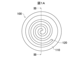
- FIG. 1A is a top view of a fixed scroll 100 that is the subject of the manufacturing process for the casting mold according to the first embodiment.
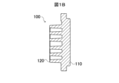
- FIG. 1B is a cross-sectional view taken along the IB-IB section line shown in FIG. 1A. Note that, for ease of understanding, FIGS. 1A and 1B show the fixed scroll 100 with the teeth facing upward.
- the fixed scroll 100 includes a base plate 110 and a scroll body 120 supported by the base plate 110.
- the shell of the scroll compressor is formed in a cylindrical shape.
- the base plate 110 is formed in a disk shape as shown in Figures 1A and 1B so that it can be fitted into the shell.
- a scroll 120 is provided on one side of the center of the base plate 110, i.e., on the top side.
- the scroll 120 has a shape in which a strip-shaped plate is bent into a spiral shape.
- the scroll 120 protrudes from the upper surface of the base plate 110 with the width direction of the plate, i.e., the extension direction of the teeth, perpendicular to the base plate 110.
- the shape of the scroll 120 allows the fixed scroll 100 to mesh with the teeth of the oscillating scroll.
- the fixed scroll 100 is incorporated into a scroll compressor (not shown), and compresses the fluid by the oscillation of the oscillating scroll while meshing with the teeth of the oscillating scroll. Next, the configuration of the oscillating scroll will be explained.
- FIG. 2A is a top view of the oscillating scroll 200 from which the mold according to the first embodiment is manufactured.
- FIG. 2B is a cross-sectional view taken along the IIB-IIB section line shown in FIG. 2A. Note that, for ease of understanding, FIGS. 2A and 2B show the oscillating scroll 200 with the teeth facing upward, as in the case of the fixed scroll 100.
- the oscillating scroll 200 includes a base plate 210, a spiral body 220 supported by the base plate 210, and a cylindrical portion 230 provided on the surface of the base plate 210 opposite the surface on which the spiral body 220 is located.
- the base plate 210 is formed in the shape of a disk with an outer diameter smaller than that of the base plate 110 of the fixed scroll 100 so that the oscillating scroll 200 can oscillate within the cylindrical shell (not shown) without interfering with the shell.
- a scroll 220 is provided on one side of the base plate 210, i.e., the top side.
- the spiral body 220 has a shape in which a strip-shaped plate is bent into a spiral shape.
- the direction in which the strip-shaped plate of the spiral body 220 spirals is the opposite direction to the spiral body 120 when viewed from above.
- the spiral body 220 protrudes from the upper surface of the base plate 210 with the width direction of the plate, i.e., the extension direction of the teeth, perpendicular to the base plate 210. Since the spiral body 220 has such a shape, the oscillating scroll 200 can mesh with the teeth of the spiral body 120 of the fixed scroll 100.
- the oscillating scroll 200 is incorporated into a scroll compressor (not shown), and oscillates to compress the fluid by meshing with the teeth of the spiral body 120 of the fixed scroll 100.
- a cylindrical portion 230 is provided on the other surface of the base plate 210, i.e., the lower surface side.
- the cylindrical portion 230 is formed with an inner diameter that allows the insertion of a crankshaft provided in a scroll compressor (not shown). When assembled in a scroll compressor, the crankshaft is inserted into the cylindrical portion 230 and connected to the crankshaft. This allows the rotation of the crankshaft to be transmitted to the cylindrical portion 230 when assembled in the scroll compressor. As a result, the cylindrical portion 230 causes the oscillating scroll 200 to oscillate.
- the fixed scroll 100 and the oscillating scroll 200 configured as described above are manufactured by casting.
- a sand mold is used that has a space, i.e., a cavity, for forming the fixed scroll 100 or the oscillating scroll 200.
- Molten metal is poured into the cavity, and the fixed scroll 100 or the oscillating scroll 200 is manufactured by allowing the molten metal to solidify.
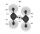
- Figure 3 is a diagram showing a simulation of the solidification state of the molten metal when casting is performed in a normal mold in which a feeder portion is arranged between the fixed scrolls 100 to be cast. Note that Figure 3 omits the illustration of the upper and lower mold halves, and shows only the molten metal 300 and the solidified molten metal.
- the outer periphery of the fixed scroll 100 solidifies first, leaving the molten metal 300 in the center of the fixed scroll 100.
- the molten metal 300 is then interrupted between the fixed scroll 100 and the feeder portion 310.
- the last solidified portion remains inside the fixed scroll 100, and shrinkage cavities occur in that portion.
- shrinkage cavities occur in the center portion of the base plate 110 where the scroll body 120 is located, the base portion of the scroll body 120, and the like.
- the scroll 220 when casting the orbiting scroll 200, the scroll 220 is provided in the center of the base plate 210, and as a result, just like in the case of the fixed scroll 100, the molten metal 300 that forms the outer periphery of the base plate 210 tends to solidify before the molten metal 300 that forms the center of the base plate 210. As a result, shrinkage cavities may occur in the center of the base plate 210. In that case, even the orbiting scroll 200 will not be able to achieve high strength.
- the casting process for casting the fixed scroll 100 or the orbiting scroll 200 uses a sand mold according to embodiment 1 that has a riser portion that is an improvement over the riser portion 310 found in a normal sand mold. That is, in embodiment 1, a sand mold is used that has a riser portion that covers the weir and the end of the cavity connected to the weir from above, and heats the weir and the end of the cavity.
- a riser refers to the supply of molten metal to prevent shrinkage or the formation of gaps in the mold cavity as the molten metal 300 solidifies, or to a pool of molten metal, but in this specification, the riser portion refers to the space that forms the latter pool of molten metal.
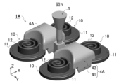
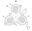
- FIG. 4 is a perspective view of the sand mold 1A according to the first embodiment.
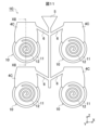
- FIG. 5 is a perspective view showing the positional relationship between the cavity 10, the feeder portion 4A, and the sprue 5 of the sand mold 1A.
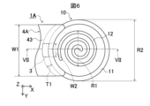
- FIG. 6 is an enlarged top view showing the positional relationship between the cavity 10 and the feeder portion 4A.
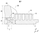
- FIG. 7 is a cross-sectional view taken along the VII-VII cutting line shown in FIG. 6.
- Fig. 4 omits the illustration of the upper and lower dies for forming the feeder portion 4A and the gate 5 of the sand mold 1A. Also, Figs. 5 to 7 omit the illustration of the upper and lower dies, as well as the core 2. Instead, Figs. 5 to 7 show the shape of the cavity 10 for casting the fixed scroll 100.
- the sand mold 1A includes a core 2 shown in FIG. 4 that forms a cavity 10, a gate 3 shown in FIG. 7 that allows molten metal 300 to flow into the cavity 10, and a riser portion 4A shown in FIG. 4 for supplying molten metal 300 to the cavity 10.
- the core 2 shown in FIG. 4 is formed from sand such as mountain sand, river sand, beach sand, synthetic sand, etc.
- the lower part of the core 2, although not shown in FIG. 4, is formed in a shape that resembles the outer shape of the upper surface of the spiral body 120 of the fixed scroll 100 described above and the outer shape of the upper surface of the base plate 110.
- the core 2 is placed between an upper mold (not shown) and a lower mold that resembles the outer shape of the lower surface of the base plate 110 described above that the fixed scroll 100 is provided with.
- the core 2, together with the upper and lower molds, forms the cavity 10 shown in FIGS. 5-7 for casting the fixed scroll 100.
- the cavity 10 has a base plate forming section 11 that forms the base plate 110 of the fixed scroll 100, and a spiral body forming section 12 that forms the spiral body 120.
- the base plate forming section 11 is connected to a dam 3 shown in Figure 7 for introducing molten metal 300 during casting.
- the base plate forming portion 11 has an end surface portion 13 that forms the outer peripheral surface of the base plate 110 of the fixed scroll 100, i.e., that forms the outer peripheral end surface.
- the dam 3 is provided adjacent to the end surface portion 13 from the outside of the cavity 10.
- the base plate forming portion 11 is a disk-shaped space, and the dam 3 communicates with that space in the diameter direction of the base plate forming portion 11 and from the outside.
- the weir 3 is the entrance to the cavity 10 through which the molten metal 300 flows into the cavity 10 during casting.
- the weir 3 is a part that is removed from the cast fixed scroll 100 after casting.
- the weir 3 is formed to be significantly smaller than the base plate 110 of the fixed scroll 100 to facilitate removal after casting.
- the shape of the weir 3 in top view, as shown in FIG. 6, is a bent rectangle having two long sides that protrude in an arc shape toward the outside of the base plate forming portion 11 and short sides that are parallel to each other.
- the long sides are smaller than the radius of the base plate forming portion 11 or the scroll diameter R1 of the scroll forming portion 12.
- the short sides are the same thickness as the wall thickness T1 of the core 2. For example, the short sides are about 3 to 15 mm.
- the cross-sectional shape of the weir 3 is rectangular as shown in FIG. 7. Its length, i.e., the length in the X direction, is the same as the wall thickness T1 of the core 2 described above.
- the height of the weir 3 in cross-sectional view, i.e., the length in the Z direction, is equal to or less than the Z direction length of the end face portion 13 of the base plate forming portion 11. For example, the length in the Z direction is 3 to 60 mm.
- the supply portion 41 of the feeder portion 4A is adjacent to the side of the weir 3 opposite to the side adjacent to the base plate forming portion 11, i.e., the -X side of the weir 3. This connects the weir 3 to the feeder portion 4A.
- the feeder section 4A functions as a molten metal reservoir that supplies the molten metal 300 to the cavity 10.
- the feeder section 4A is equipped with a supply section 41 that is connected to the weir 3 to supply the molten metal 300, and a heating section 42 that has a portion facing the weir 3 and the end of the base plate forming section 11 that is connected to the weir 3, and heats the weir 3 and the end of the base plate forming section 11 when the molten metal 300 is poured in.
- the supply section 41 is connected to the weir 3 and functions as a connection section for the feeder section 4A.
- the supply section 41 is formed in a rectangular shape with two long sides concave inward in an arc shape when viewed from above. This is because, as shown in FIG. 5, the supply section 41 is adjacent to the base plate forming section 11 between the base plate forming sections 11 of the cavity 10, and these base plate forming sections 11 are circular when viewed from above. As shown in FIG. 7, the supply section 41 extends to a position higher than the base plate forming section 11 of the cavity 10 while maintaining its shape when viewed from above.
- the supply section 41 is connected to the weir 3 described above midway. As a result, when the molten metal 300 is poured during casting, the supply section 41 supplies the molten metal 300 to the base plate forming section 11.
- the heating section 42 extends from the supply section 41 to a position higher than the spiral body forming section 12 of the cavity 10, making it possible to supply the molten metal 300 to the spiral body forming section 12 during casting. Furthermore, the heating section 42 protrudes from the supply section 41 above the outer periphery of the weir 3 and the base plate forming section 11, and heats the outer periphery of the weir 3 and the base plate forming section 11 with the heat of the molten metal 300 during casting.
- the heating section 42 is provided above the supply section 41, and extends from the upper end of the supply section 41 to a position sufficiently higher than the spiral body forming section 12 of the cavity 10.
- the upper end of the heating section 42 is 10 mm or more higher than the spiral body forming section 12. This allows the heating section 42 to flow the molten metal 300 into the supply section 41 during casting, and to replenish the molten metal 300 to the entire cavity 10, including the spiral body forming section 12.
- the heating section 42 also protrudes from the supply section 41 towards the cavity 10. That is, the heating section 42 protrudes from the supply section 41 towards the +X side. Furthermore, the position from which the heating section 42 protrudes is a position spaced upward from the outer periphery of the base plate forming section 11 of the cavity 10. As a result, the heating section 42 covers the outer periphery of the base plate forming section 11 from above. In other words, the heating section 42 overlaps with the outer periphery of the base plate forming section 11 when viewed from a direction perpendicular to the plate surface of the base plate forming section 11, that is, when viewed from above or below.
- the heating section 42 is formed by the outer surface of the core 2 (not shown in FIG. 7 ), and therefore protrudes upward from the base plate forming section 11 by the thickness T2 of the core 2. That is, the heating section 42 protrudes from a position on the +Z side of the base plate forming section 11, which is separated from the base plate forming section 11 by the thickness T2 of the core 2.
- the heating section 42 also protrudes from the supply section 41 toward the +X side by a distance L greater than the thickness T1 of the core 2. That is, the heating section 42 protrudes toward the +X side by a distance greater than the X-direction length of the weir 3.
- the heating section 42 protrudes, for example, from the spiral body forming section 12 to a position separated by the thickness T1 of the core 2 in the -X direction. This causes the heating section 42 to face the weir 3.
- the heating section 42 also faces the -X end of the top surface section 14 of the base plate forming section 11.
- the heating portion 42 has a facing portion 43 that faces the weir 3 and the ⁇ X end portion of the top surface portion 14 .
- the thickness T1 of the core 2 in the X direction may be different from the thickness T2 of the core 2 in the Z direction, or may be the same as the thickness T2.
- the width W1 of the facing portion 43 in top view is equal to or greater than the width W2 of the weir 3.
- the width W2 of the weir 3 is 10-20% of the scroll diameter R1
- the minimum value of the width W1 of the facing portion 43 is 10-20% of the scroll diameter R1.
- the minimum value of the width W1 of the facing portion 43 is 50 mm smaller than the scroll diameter R1.
- the maximum value of the width W1 of the facing portion 43 is 50 mm larger than the diameter R2 of the base plate forming portion 11.
- the facing portion 43 has this width W1 and protrudes the above-mentioned distance L, thereby completely covering the weir 3 from above.
- the facing portion 43 faces the weir 3 or the -X end of the top surface 14 of the base plate forming portion 11 at a distance equal to the thickness T2 of the core 2. This is because the facing portion 43 is formed by the outer surface of the core 2.
- the heating portion 42 transfers the heat of the molten metal 300 from the facing portion 43 through the core 2 to the weir 3 and the -X end of the top surface 14 of the base plate forming portion 11.
- the heating portion 42 heats the weir 3 and the -X end of the top surface 14 of the base plate forming portion 11 during casting.
- the sand mold 1A makes the molten metal 300 at the weir 3 and the molten metal 300 flowing under the top surface 14 of the base plate forming portion 11 less likely to solidify than the molten metal 300 in other parts during casting.
- the molten metal 300 can be replenished from the feeder portion 4A until all of the molten metal 300 that has flowed into the cavity 10 solidifies, preventing the occurrence of shrinkage cavities inside the cavity 10. This allows the sand mold 1A to cast a fixed scroll 100 with sufficient strength.
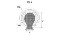
- FIG. 8A is a simulation diagram showing the solidification of molten metal 300 after a certain time has elapsed since molten metal 300 was poured into a normal sand mold when fixed scroll 100 is cast using the normal sand mold.
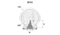
- FIG. 8B is a simulation diagram showing the solidification of molten metal 300 after a certain time has elapsed since molten metal 300 was poured into sand mold 1A when fixed scroll 100 is cast using sand mold 1A according to embodiment 1.
- the sand mold 1A according to the first embodiment has a smaller depth D relative to the width W of the molten metal 300 than a normal sand mold. Specific values are shown in Table 1.
- the depth D relative to the width W of the molten metal 300 is less than half that of a normal sand mold. This shows that in the sand mold 1A, the molten metal 300 forming the outer periphery of the fixed scroll 100 is less likely to solidify before the molten metal 300 forming the central portion. As a result, in the sand mold 1A, the molten metal 300 forming the outer periphery of the fixed scroll 100 is less likely to solidify first, and the molten metal 300 forming the central portion of the fixed scroll 100 is less likely to become isolated. In this way, in the sand mold 1A, the molten metal 300 forming the central portion of the fixed scroll 100 is less likely to become isolated and shrinkage cavities are less likely to occur than in a normal sand mold.
- the sand mold 1A described above is an example of a casting mold as defined in the present disclosure.
- the upper and lower molds are an example of a main mold as defined in the present disclosure.
- the supply section 41 of the feeder section 4A is an example of a connection section as defined in the present disclosure.
- the heating section 42 or the opposing section 43 of the feeder section 4A is an example of an opposing section as defined in the present disclosure.
- the end surface section 13 is an example of a first surface section as defined in the present disclosure.
- the top surface section 14 of the base plate forming section 11 is an example of a second surface section as defined in the present disclosure.
- the fixed scroll 100 described above is an example of a member having a plate-like portion and a protruding portion protruding from one of the plate surfaces of the plate-like portion as defined in this disclosure.
- the base plate 110 and the scroll body 120 of the fixed scroll 100 are an example of a plate-like portion and a protruding portion as defined in this disclosure.
- the sand mold 1A may be used to cast the oscillating scroll 200.
- the oscillating scroll 200 is an example of a member having the above-mentioned plate-shaped portion and a protruding portion protruding from one plate surface of the plate-shaped portion.
- the base plate 210 of the oscillating scroll 200 is also an example of the above-mentioned plate-shaped portion.
- the scroll body 220 and cylindrical portion 230 of the oscillating scroll 200 are examples of the above-mentioned protruding portion.
- the fixed scroll 100 and the oscillating scroll 200 described above are manufactured by (1) a casting process in which molten metal is poured into a sand mold 1A and solidified, and (2) a post-processing process after the casting process in which the sand mold 1A is disassembled, the sand is removed, and burrs and other parts where the molten metal has solidified at the gate 3, the riser portion 4A, etc. are removed from the cast fixed scroll 100 or the oscillating scroll 200.
- the above-mentioned casting process is an example of the casting process referred to in this disclosure.
- the feeder section 4A has a heating section 42 that covers the weir 3 and the end of the top surface section 14 of the base plate forming section 11 adjacent to the weir 3 from the supply section 41, and warms the weir 3 and the end of the top surface section 14 with the heat of the molten metal when the molten metal flows in. Therefore, in the sand mold 1A, the molten metal 300 in the weir 3 and the molten metal 300 flowing through the top surface section 14 are unlikely to solidify.
- the sand mold 1A can supply the molten metal 300 from the feeder section 4A via the weir 3 and the top surface section 14 until all of the molten metal 300 inside the cavity 10 solidifies. As a result, the sand mold 1A can prevent the occurrence of shrinkage cavities in the fixed scroll 100. This allows the sand mold 1A to cast a fixed scroll 100 with high strength.
- the construction of the sand mold 1A is simple, as it is sufficient that the riser portion 4A covers the ends of the weir 3 and the top surface portion 14 of the base plate forming portion 11 and faces the ends of the weir 3 and the top surface portion 14. As a result, the sand mold 1A is easy to manufacture.
- the sand mold 1A has four cavities 10, but the configuration including each of the cavities 10, the weirs 3 connected to each of the cavities 10, and the feeder portions 4A connected to each of the cavities 10 may be called a casting mold or sand mold. In that case, in the first embodiment, the combination of these four casting molds or sand molds may be called a casting mold system.
- the sand mold 1A has four cavities 10 and two feeder portions 4A in order to cast four fixed scrolls 100.
- the sand mold 1A is not limited to this.
- the feeder portion 4A has heating portions 42 corresponding to each of the plurality of cavities 10.
- one riser portion 4B is provided for each of the three cavities 10.
- FIG. 9 is a top view of sand mold 1B according to embodiment 2. Note that the upper and lower molds and core 2 are omitted from FIG. 9 for ease of understanding.
- the sand mold 1B has three cavities 10 and one feeder portion 4B connected to the three cavities 10.
- Each of the cavities 10 is formed to have the same shape and size as the cavity 10 described in embodiment 1.
- the cavities 10 are arranged at a fixed distance from the center C, at 120° intervals clockwise around the center C shown in FIG. 9.
- a weir 3 is adjacent to each of the cavities 10, in the same relative positional relationship as described in embodiment 1.
- each of the weirs 3 is connected to a supply section 41 (not shown in FIG. 9) of the feeder section 4B.
- the feeder 4B has the same number of opposing parts 43 of the heating section 42 as the cavities 10, that is, three, as described in the first embodiment, although not shown in FIG. 9.
- Each opposing part 43 faces the dam 3 in the same relative positional relationship as described in the first embodiment.
- each opposing part 43 faces the end of the top surface 14 of the base plate forming part 11, which is not shown in FIG. 9, provided in each cavity 10.
- the feeder portion 4B is provided with the opposing portion 43 of the heating portion 42 for each cavity 10, similar to the first embodiment. Therefore, in the sand mold 1B, like the first embodiment, it is possible to prevent the occurrence of shrinkage cavities in the fixed scroll 100. As a result, the sand mold 1B can cast a fixed scroll 100 with high strength.
- sand mold 1B is an example of a mold as defined in this disclosure. Or, it is an example of a mold system.
- the above-mentioned feeder 4B has a relatively large shape covering the outer periphery of each cavity 10 from the center C.
- the feeder 4B may be provided with a cylindrical through-portion 44 as shown in Figure 9.
- the through-portion 44 may be cylindrical or may be prismatic, for example triangular.
- the shape of the feeder portion 4B when viewed from above may be an arc shape that follows the outer periphery of the base plate forming portion 11 of each cavity 10, and in this case, the arc shape may cover the outer periphery of the base plate forming portion 11.
- the space between the cavities 10 may be either linear or curved.
- the feeder 4B is connected to one gate 5 by one runner 6.
- the relationship between the feeder 4B and the gate 5 is not limited to this.
- the feeder 4B may be connected to one gate 5 by a plurality of runners 6.
- FIG. 10 is a top view of a modified sand mold 1B according to embodiment 2. As with FIG. 9, the upper and lower molds and the core 2 are omitted in FIG. 10 for ease of understanding.
- the sand mold 1B may have six cavities 10.
- each of the cavities 10 may be arranged at a certain distance from the center C, at 60° intervals clockwise around the center C.
- the feeder 4B may have an annular shape in which the center of a hexagon is hollowed out in a hexagonal shape with each side recessed inward in an arc shape when viewed from above.
- the gate 5 may be arranged in the center of the internal space of the annular feeder 4B when viewed from above.
- a runner 6 may extend from each of the cavities 10. More specifically, a total of six runners 6 may extend toward the gate 5 from each of six locations of the supply section 41 of the feeder 4B adjacent to the weir 3 connected to each of the cavities 10. This is because even in this form, the sand mold 1B can pour the molten metal 300 into the six cavities 10 from one gate 5.
- the feeder parts 4A, 4B cover the weir 3 and the end of the top surface part 14 of the base plate forming part 11 of the cavity 10 from above.
- the feeder parts 4A, 4B are not limited to this.
- the feeder sections 4A and 4B may have a supply section 41 connected to the weir 3 and supplying the molten metal 300 to the weir 3, and a heating section 42 that is located at a position separated from the weir 3 and the end of the top surface section 14 of the base plate forming section 11 adjacent to the weir 3 in a direction perpendicular to the top surface section 14 and overlaps the weir 3 and the end of the top surface section 14 when viewed from a direction perpendicular to the top surface section 14, and that heats the weir 3 and the end of the top surface section 14 with the heat of the molten metal 300 when the molten metal 300 flows in. Therefore, in the feeder sections 4A and 4B, the opposing portion 43 provided in the heating section 42 does not have to cover the weir 3 and the end of the top surface section 14 from above.
- the sand mold 1C according to embodiment 3 has a facing portion 45 where the riser portion 4C covers the ends of the weir 3 and the top surface portion 14 from the front.
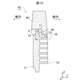
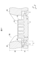
- FIG. 11 is a front view of a sand mold 1C according to embodiment 3.
- FIG. 12 is a cross-sectional view taken along the line XII-XII shown in FIG. 11.
- the sand mold 1C has four cavities 10. In each cavity 10, the plate surface of the base plate forming portion 11 of the cavity 10 faces in the front-to-rear direction. A riser portion 4C is provided on the base plate forming portion 11.
- the feeder section 4C is provided above the weir 3 provided at the upper end of the base plate forming section 11.
- the bottom surface of the feeder section 4C extends from above the weir 3 to the front F, and then bends downward.
- the bottom surface of the feeder section 4C is lowered to a position spaced apart from the spiral body forming section 12 of the cavity 10 by the thickness T3 of the core 2.
- the bottom surface of the feeder section 4C covers the upper end of the weir 3 and the top surface section 14 of the base plate forming section 11 from the front F.
- the bottom surface of the feeder section 4C has an opposing portion 45 that faces the weir 3 and the upper end of the top surface section 14.
- the wall thickness T3 of the core 2 adjacent to the spiral body forming portion 12 may be different from or the same as the wall thicknesses T1 and T2 described in the first embodiment.
- the relative positional relationship of the facing portion 45 to the weir 3 and the upper end of the top surface portion 14 is the same as the relative positional relationship of the facing portion 43 described in embodiment 1 to the end of the weir 3 and the top surface portion 14, except that the orientation of the facing portion 45 is different.
- the feeder portion 4C transfers the heat of the molten metal 300 from the facing portion 45 through the core 2 to the weir 3 and the upper end of the top surface portion 14 of the base plate forming portion 11.
- the sand mold 1C As a result, in the sand mold 1C, the molten metal 300 in the weir 3 and the molten metal 300 flowing along the top surface portion 14 of the base plate forming portion 11 during casting is less likely to solidify than the molten metal 300 in other parts. As a result, the sand mold 1C can be replenished with molten metal 300 from the feeder portion 4C until all of the molten metal 300 solidifies. This allows the sand mold 1C to prevent shrinkage cavities from occurring inside the cavity 10 and cast a fixed scroll 100 with sufficient strength.
- the facing portion 45 of the feeder portion 4C can heat the weir 3 and the end of the top surface portion 14 of the base plate forming portion 11 with the heat of the molten metal 300 during casting, thereby improving heat retention.
- the sand mold 1C can prevent the occurrence of shrinkage cavities in the fixed scroll 100 and cast a fixed scroll 100 with high strength.
- sand mold 1C is an example of a mold as defined in this disclosure. Or, it is an example of a mold system.
- the feeder sections 4A, 4B may include a supply section 41 connected to the weir 3 and supplying molten metal 300 to the weir 3, and a heating section 42 located at a position separated from the weir 3 and the end of the top surface section 14 of the base plate forming section 11 adjacent to the weir 3 in a direction perpendicular to the top surface section 14, and located at a position overlapping the weir 3 and the end of the top surface section 14 when viewed from the direction perpendicular to the top surface section 14, and which warms the weir 3 and the end of the top surface section 14 with the heat of the molten metal 300 when the molten metal 300 flows in.
- the sand mold 1D according to embodiment 4 has a riser portion 4D that is below the ends of the dam 3 and the top surface portion 14 and has an opposing portion 43 that faces the ends of the dam 3 and the top surface portion 14.
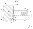
- FIG. 13 is a cross-sectional view of a sand mold 1D according to embodiment 4. Note that FIG. 13 shows a cross-sectional view taken along a cut line that cuts the same location as the VII-VII cut line shown in FIG. 6.
- the cavity 10 of the sand mold 1D according to embodiment 4 is arranged vertically symmetrically to the cavity 10 described in embodiment 1.
- the base plate forming part 11 is arranged on the upper side, and the spiral body forming part 12 is arranged on the lower side.
- the top surface part 14 and the bottom surface part 15 of the base plate forming part 11 extend toward the outer periphery, and the weir 3 is connected to the end of the extension.
- the weir 3 is formed to have the same shape and size as described in the first embodiment. As a result, the weir 3 extends horizontally from the outer periphery of the base plate forming part 11, specifically in the X direction. The weir 3 is connected to the supply part 41 of the feeder part 4D described in the first embodiment at its end.
- a heating section 42 is disposed below the supply section 41.
- the supply section 41 is provided in the horizontal direction of the weir 3 and the base plate forming section 11 of the cavity 10. Furthermore, the heating section 42 is provided below the weir 3 and the base plate forming section 11 by the thickness T2 of the core 2.
- the heating section 42 protrudes from the supply section 41 toward the side where the spiral body forming section 12 of the cavity 10 is located, i.e., toward the +X side.
- the shape of the heating section 42 is a trapezoid whose upper and lower sides extend in the X direction when viewed in an XZ cross section.
- the protruding length of the heating section 42 is such that the +X end of the heating section 42 reaches a position that is away from the spiral body forming section 12 of the cavity 10 by the thickness T2 of the core 2.
- the +Z surface of the heating section 42 is horizontal and faces the weir 3 and the top surface 14 of the base plate forming section 11.
- the heating section 42 has an opposing portion 43.
- the feeder section 4D warms the ends of the weir 3 and the top surface 14 of the base plate forming section 11 with the heat of the molten metal 300, as in the case described in embodiment 1-3. For this reason, even with the sand mold 1D, shrinkage cavities are unlikely to occur in each of the cavities 10. As a result, even with the sand mold 1D, a fixed scroll 100 with high strength can be cast.
- the cavity 10 is vertically symmetrical to that in the first embodiment.
- the spiral body forming portion 12 is disposed below the base plate forming portion 11, and the top surface portion 14 of the base plate forming portion 11 faces downward.
- the top surface portion 14 extends horizontally.
- the feeder portion 4D protrudes below the dam 3 and the base plate forming portion 11. Therefore, in the sand mold 1D according to the fourth embodiment, as in the first embodiment, the feeder portion 4D can heat the ends of the dam 3 and the top surface portion 14 of the base plate forming portion 11 with the heat of the molten metal 300 during casting, thereby improving heat retention.
- the sand mold 1D can cast a fixed scroll 100 with high strength by preventing the occurrence of shrinkage cavities in the fixed scroll 100.
- the heating unit 42 may be disposed not only below the supply unit 41 but also above the supply unit 41.
- the spiral body forming unit 12 may be disposed above the base plate forming unit 11, as in the first embodiment.
- FIG. 14 is a cross-sectional view of a modified example of sand mold 1D according to embodiment 4. Note that, like FIG. 13, FIG. 14 shows a cross-sectional view taken along a cut line that cuts the same location as cut line VII-VII shown in FIG. 6.
- the sand mold 1D may have a cavity 10 in which the spiral body forming part 12 is disposed above the base plate forming part 11.
- the top surface part 14 of the base plate forming part 11 may be facing upward.
- the feeder part 4D may have a heating part 42 provided above the supply part 41, as in the first embodiment, and a heating part 46 provided below the supply part 41, as in the fourth embodiment.
- the heating section 42 protrudes in the +X direction from the supply section 41, so that the heating section 42 has an opposing portion 43 that faces the ends of the top surface 14 of the base plate forming section 11 of the weir 3 and the cavity 10.
- the heating section 46 protrudes in the +X direction from the supply section 41, so that the heating section 46 has an opposing portion 47 that faces the ends of the bottom surface 15 of the base plate forming section 11 of the weir 3 and the cavity 10. This is because, with such a configuration, the heating sections 42 and 46 can heat the weir 3 and the ends of the top surface 14 of the base plate forming section 11 from above and below with the heat of the molten metal 300 during casting, thereby improving heat retention.
- the heating unit 46 is an example of a second heating unit as defined in this disclosure.
- the sand mold 1D is an example of a casting mold as defined in this disclosure.
- sand mold 1A-1D has multiple cavities 10 and is capable of casting multiple fixed scrolls 100, but sand mold 1A-1D is not limited to this.
- Sand mold 1A-1D only needs to have at least one cavity 10. And it only needs to be capable of casting the same number of fixed scrolls 100 as there are cavities 10.
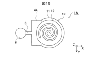
- FIG. 15 is a top view of a modified sand mold 1A according to embodiment 1. Note that the directions of the X-axis, Y-axis, and Z-axis in the orthogonal coordinate system XYZ shown in FIG. 15 are the same as those in the orthogonal coordinate system XYZ shown in FIG. 4 to FIG. 7. The same also applies to FIG. 16 and FIG. 17 described later.
- the sand mold 1A may have one cavity 10 and one riser 4A. Naturally, this configuration also makes it possible to prevent shrinkage cavities from occurring and produce a fixed scroll 100 with high strength.
- sand molds 1A-1D have only one dam 3 for each cavity 10, but the number of dams 3 is arbitrary as long as the positional relationship with the opposing parts 43, 45 of feeder sections 4A-4D is maintained.
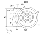
- FIG. 16 is a top view of another modified example of sand mold 1A according to embodiment 1.
- the sand mold 1A may have three dams 3.
- the sand molds 1A-1D may have multiple dams 3. Even in this form, as long as the positional relationship between the opposing parts 43, 45 of the feeder sections 4A-4D is maintained, it is possible to prevent the occurrence of shrinkage cavities and manufacture a fixed scroll 100 with high strength. In this case, it is preferable that the width W2 of the dams 3 is small so that they can be easily removed after casting.
- FIG. 17 is a top view of yet another modified example of sand mold 1A according to embodiment 1.
- the sand mold 1A may have two weirs 3.
- each weir 3 is provided on the outer periphery of the disk-shaped base plate forming portion 11 of the cavity 10, and the two weirs 3 face each other across the center of the base plate forming portion 11.
- the same number of feeder portions 4A as the number of weirs 3 may be provided, and the heating portion 42 of each feeder portion 4A may face the weir 3 and the end of the base plate forming portion 11 connected to that weir 3. This is because, with this configuration, the occurrence of shrinkage cavities can be prevented with each weir 3.
- the facing parts 43, 45, 47 are arranged parallel to the weir 3 and face each other. Furthermore, the facing parts 43, 45, 47 are arranged parallel to the end of the top surface portion 14 and face each other. However, the facing parts 43, 45, 47 are not limited to this.
- the feeder parts 4A-4D are provided at a position separated from the weir 3 and the end of the top surface portion 14 of the base plate forming part 11 adjacent to the weir 3 in a direction perpendicular to the top surface portion 14, and are provided at a position overlapping the weir 3 and the end of the top surface portion 14 when viewed from a direction perpendicular to the top surface portion 14, and have a heating part 42 that warms the weir 3 and the end of the top surface portion 14 with the heat of the molten metal 300 when the molten metal 300 flows in. Therefore, the facing parts 43, 45, 47 do not have to be parallel to the weir 3 and the end of the top surface portion 14.
- the facing portions 43, 45, 47 may be inclined with respect to the ends of the dam 3 and the top surface portion 14.
- the facing portions 43, 45, 47 may be inclined so that the distance between the dam 3 or the top surface portion 14 increases as the distance from the dam 3 increases toward the side where the top surface portion 14 is located. With such an inclination, the closer the portion is to the dam 3, the warmer it becomes during casting, which can prevent the occurrence of shrinkage cavities.
- the facing portions 43, 45, 47 do not need to be flat, and may be uneven or curved.
- sand mold 1A-1D casts fixed scroll 100, i.e., a scroll member.
- the casting object of sand mold 1A-1D is not limited to this.
- Sand mold 1A-1D may be any casting mold that casts a member having a plate-shaped portion and a protruding portion that protrudes from one of the plate surfaces of the plate-shaped portion. Therefore, sand mold 1A-1D may be any casting mold that casts a member that satisfies this condition.
- FIG. 18 is a perspective view of a heat sink 7 that is the subject of sand mold manufacturing in another embodiment.
- the heat sink 7 comprises a support plate 71 and a plurality of pin-shaped fins 72 arranged in a matrix.
- the heat sink 7 may be cast by applying the sand mold 1A-1D.
- the support plate 71 is cast by applying the base plate forming portion 11 of the cavity 10 provided in the sand mold 1A-1D, and the spiral body forming portion 12 of the cavity 10 is replaced with a fin forming portion to cast the plurality of fins 72.
- Fins 72 may be formed in a pin shape, or in a flat, corrugated, arc-shaped, or quadratically curved plate shape, with the end faces of the plate supported by support plate 71.
- fins 72 When fins 72 are flat or corrugated, fins 72 may be arranged parallel to each other.
- each fin 72 may be arranged so that its surface extends radially from the center of the surface of support plate 71.
- the mold, mold system, and method of manufacturing the component are not limited to the above-described embodiments, and various modifications and substitutions can be made thereto.
- Various aspects of the present disclosure are described below as appendices.
- the member is a fixed scroll or a swing scroll of a scroll compressor,
- the plate-shaped portion is a base plate provided in the fixed scroll or the orbiting scroll,
- the protruding portion is a spiral body provided on the fixed scroll or the orbiting scroll and protruding from one plate surface of the base plate.
- the member is a heat sink, the plate-shaped portion is a support plate included in the heat sink,
- the protrusion is a fin provided on the heat sink, supported by the support plate, and protruding from one plate surface of the support plate.
- a plurality of molds each for casting a member having a plate-shaped portion and a protruding portion protruding from one plate surface of the plate-shaped portion, a cavity including a first surface portion for forming an end surface of the plate-shaped portion and a second surface portion for forming either one of the plate surfaces of the plate-shaped portion and the other plate surface, the cavity into which molten metal flows and into which the plate-shaped portion and the protrusion are cast when the molten metal solidifies; a weir provided adjacent to the first surface portion from the outside of the cavity for allowing the molten metal to flow into the cavity; a feeder section including a supply section connected to the weir and supplying the molten metal to the weir, and a heating section provided at a position spaced from the weir and an end of the second surface section adjacent to the weir in a direction perpendicular to the second surface section and overlapping the weir and the end of the second surface section when viewed in the direction
Landscapes
- Engineering & Computer Science (AREA)
- Mechanical Engineering (AREA)
- Molds, Cores, And Manufacturing Methods Thereof (AREA)
Priority Applications (1)
| Application Number | Priority Date | Filing Date | Title |
|---|---|---|---|
| JP2025525988A JPWO2024252823A1 (enExample) | 2023-06-06 | 2024-04-26 |
Applications Claiming Priority (2)
| Application Number | Priority Date | Filing Date | Title |
|---|---|---|---|
| JP2023-093252 | 2023-06-06 | ||
| JP2023093252 | 2023-06-06 |
Publications (1)
| Publication Number | Publication Date |
|---|---|
| WO2024252823A1 true WO2024252823A1 (ja) | 2024-12-12 |
Family
ID=93795216
Family Applications (1)
| Application Number | Title | Priority Date | Filing Date |
|---|---|---|---|
| PCT/JP2024/016597 Pending WO2024252823A1 (ja) | 2023-06-06 | 2024-04-26 | 鋳型、鋳型システムおよび部材の製造方法 |
Country Status (2)
| Country | Link |
|---|---|
| JP (1) | JPWO2024252823A1 (enExample) |
| WO (1) | WO2024252823A1 (enExample) |
Citations (2)
| Publication number | Priority date | Publication date | Assignee | Title |
|---|---|---|---|---|
| US20030019603A1 (en) * | 2001-07-26 | 2003-01-30 | Williamson Warren G. | Green Sand casting method and apparatus |
| US20130087299A1 (en) * | 2011-10-03 | 2013-04-11 | Warren G. Williamson | Methods of casting scroll compressor components |
-
2024
- 2024-04-26 JP JP2025525988A patent/JPWO2024252823A1/ja active Pending
- 2024-04-26 WO PCT/JP2024/016597 patent/WO2024252823A1/ja active Pending
Patent Citations (2)
| Publication number | Priority date | Publication date | Assignee | Title |
|---|---|---|---|---|
| US20030019603A1 (en) * | 2001-07-26 | 2003-01-30 | Williamson Warren G. | Green Sand casting method and apparatus |
| US20130087299A1 (en) * | 2011-10-03 | 2013-04-11 | Warren G. Williamson | Methods of casting scroll compressor components |
Also Published As
| Publication number | Publication date |
|---|---|
| JPWO2024252823A1 (enExample) | 2024-12-12 |
Similar Documents
| Publication | Publication Date | Title |
|---|---|---|
| BRPI0612788B1 (pt) | Camisa de cilindro, bloco de cilindro e método para fabricação de camisa de cilindro | |
| JP2009274098A (ja) | 低圧鋳造用砂型及びそれを利用した低圧鋳造装置 | |
| JP5960106B2 (ja) | キャリパ用鋳造装置に用いる金型、キャリパ用鋳造装置、およびキャリパの製造方法 | |
| CN104936721A (zh) | 具有冒口的功能性连接的、用于制造铸件,特别是气缸体和气缸盖的方法和铸模 | |
| WO2024252823A1 (ja) | 鋳型、鋳型システムおよび部材の製造方法 | |
| JP2012101239A (ja) | アルミニウム製ヒートシンク及びその製造方法 | |
| JP2002346694A (ja) | マルチゲート鋳造用金型及び鋳造方法 | |
| CN107002593A (zh) | 内燃机用活塞、该活塞的制造装置以及制造方法 | |
| JP5594122B2 (ja) | 鋳型及び鋳型を用いた鋳造方法、並びに鋳型の設計方法 | |
| JP7371322B2 (ja) | 液冷用アルミヒートシンク及びその製造方法 | |
| JP2022010249A (ja) | 射出成形用金型 | |
| JP2010197437A (ja) | 成形プラスチックレンズ及びその成形型 | |
| JP3040776B1 (ja) | 鋳ぐるみ材料の支持方法 | |
| JP2002059243A (ja) | ディスクブレーキの鋳造装置 | |
| JPWO2024252823A5 (enExample) | ||
| JPH01202338A (ja) | 鋳造方法及び消失模型 | |
| JP7542984B2 (ja) | 鉛蓄電池用格子体 | |
| JPH09207136A (ja) | 樹脂成形用金型およびその製造方法 | |
| JP7556710B2 (ja) | バルブのボデーとバルブのボデーの製造方法 | |
| JPH0417942A (ja) | 鋳造用金型 | |
| JP2025140455A (ja) | 鋳ぐるみ品 | |
| JPS6295948A (ja) | 鋳込回転子の製造方法 | |
| JP2005066676A (ja) | タイヤ加硫用金型の製造に用いる石膏鋳型及びタイヤ加硫用金型の製造に用いる石膏鋳型の製造方法 | |
| JP2023177032A (ja) | 鋳造用中子および中空鋳物の製造方法 | |
| JPH0310422B2 (enExample) |
Legal Events
| Date | Code | Title | Description |
|---|---|---|---|
| 121 | Ep: the epo has been informed by wipo that ep was designated in this application |
Ref document number: 24819060 Country of ref document: EP Kind code of ref document: A1 |
|
| WWE | Wipo information: entry into national phase |
Ref document number: 2025525988 Country of ref document: JP |
|
| WWE | Wipo information: entry into national phase |
Ref document number: 2501006182 Country of ref document: TH |